

Page 1
GB
B.E.G.
LUXOMAT® Indoor 180/R-2W UK
Operating and mounting Instruction for B.E.G.-Occupancy detector as wallswitch Indoor 180/R-2W UK
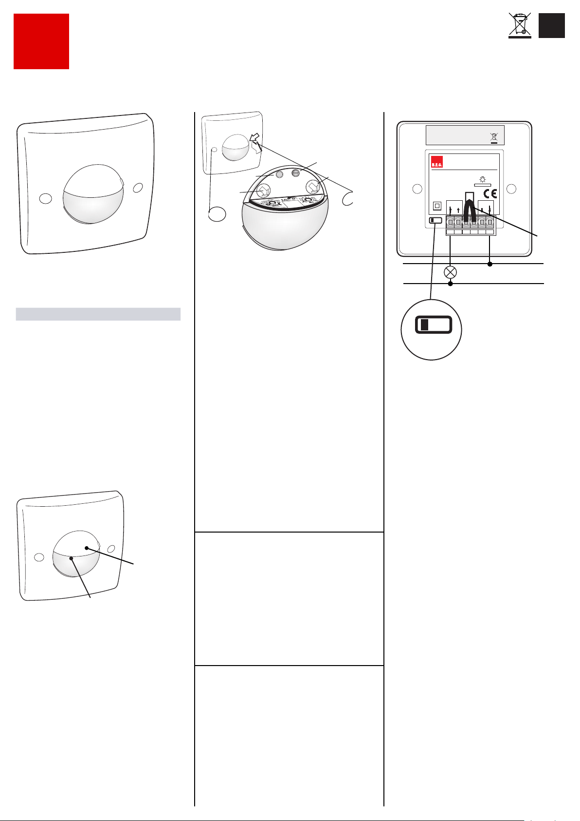
Connect wiring as shown:
contains RECHARGEABLE BATTERIES:
Fig.1
CAUTION: Have all work involving the 230 VAC mains supply
carried out by a qualied electrician!
Before starting disconnect the mains !
Article detection angle Part.-Nr.
Indoor 180R 2W UK 180° 92615
1. Product description
The LUXOMAT® Indoor 180-R/2W UK is a occupancy detec-
tor designed for ush-mounting in indoor lighting applications.
The Indoor 180 utilizes infrared- and accoustic- sensing
technology to detect the presence and movement of persons
(as well the infrared-radiation of larger animals and objects).
The sensor contains 2 red LEDs:
LED 1 for indication of
movements (in normal operation)
lux-level (in TEST mode)
LOW BATTERY/2hr charging status
LED 2 for sound indication
LED-2
Sound
LED-1
Movement/Lux-level
Low Battery
Furthermore it contains a twilight (Lux) sensor, a microphone
and a timer.
Lux-level , microphone and timer can be set here:
remove top cover as shown, this will give access to the controls.
Please follow the markings on the at top of the lens for
adjustment.
Fig.2
MIC-SOUND
RESET
LUX
Function:
(Assuming the unit is switched OFF, 230 VAC is present and
battery is charged).
Once the set twilight level is reached (=dark), the Indoor 180
will react only to detected movements and turn ON the relay,
thus illuminating the room, until no further movements or sounds
are detected and the internal timer elapses.
Once switched ON, each detected movement and/or sound will
restart the timer interval thus prolonging the ON-period.
Once the relay is switched OFF, the accoustic sensor remains
active for another 8-10 sec, to allow the relay to be re-triggered
by sounds or noises into ON state within this period.
2-wire installation:
The Indoor 180-R/2W-UK model has been specically designed
to replace manually operated light-switches in so called 2-wire
installation.
2-wire installations pose the problem, that once the relay turns
ON the connected luminaires, the powersupply for the sensor
is cut-off.
The solution to this problem is the use of a rechargeable battery,
which will be charged while the luminaires are OFF and which
will supply the sensor while the luminaires are switched ON.
In ON state the sensor will draw power from the battery and
constantly monitor the battery voltage.
Once the battery voltage drops to a dened LOW-BATTERY
value, the sensor will switch OFF the relay and enforce a
2hrs long charging period.
The LED-1 will quickly ash!
(Please note: during this 2hrs-period , the unit remains OFF and
will not react to any movement or sound)
If no mains supply is present, the battery will discharge further
and at some point in time the deep-discharge protection will kick
in and shut down the sensor entirely.
TIME
Fig.3
2. Prior to Installation
Before installation the following has to be considered:
• The LUXOMAT
installation in standard switch ushmount boxes.
• The recommended xing height is 1.10 - 2.2m
• No parallel installation of units is allowed/
recommended.
• The connect luminaire load must not exceed
Ohmic load 3000W, 10A, cosϕ= 1
Inductive load 1500VA, 5A, cosϕ= 0.5
Electronic ballast 35x 50W 140 uF max.
• There must be no obstacles in the view of the sensor, since
infrared rays cannot penetrate solid materials.
• The LUXOMAT® Indoor 180 is an automatic light
switch which cannot be used in intrusion applications.
The minimum load must exceed 50 W. If not, please
install the capacitor.
®
Indoor 180 is designed for the
3. Installation
The 230VAC mains to be switched OFF
®
The LUXOMAT
box. The location height on the wall should be between
1.10 - 2.20 m.
Indoor 180 ts into a standard ushmounting
6 xNiMH/30AAAAH
1.2V/300mAh
LUXOMAT
INDOOR 180-R/2W-UK
± 10% , 50-60Hz
230VAC
2300W/10A/cos=1
1150VA/5A/cos=0.5
IP20
ON OFF
L
N
Attention:
S
ON OFF
Note:
There is a pre-inserted shunt (thick wire) .
In normal operation this shunt must be installed!
Do not remove!
Setting into operation:
Note:
The battery is in most cases discharged due to prolonged period
of storage and requires charging!
Once connections are in place and the unit is securely fastened,
turn on mains supply.
Scenario A:
Battery is discharged! - Lights remain OFF!
LED-1 shall light up and ash quickly to indicate
LOW BATTERY and sensor will remain for 2hrs in charging
mode = relay OFF.
Scenario B:
Battery is sufciently charged! - Lights turn ON
LED-1 shall light up and ash slowly for start-up period of
60secs. After start-up period unit is operational.
Scenario C:
Battery is discharged! - BUT light turn ON!!
LED-1/LED-2 do not ash , relay does not switch!
In this unlikely case the unit cannot recover without removing the
SHUNT:
Turn OFF 230 VAC mains supply and remove shunt, than
reconnect 230VAC.
Without shunt installed , the load is disconnected from the relay
and regardless of relay state , charging should resume and LED1 should ash quickly (perhaps with some delay) .
Actions in scenarios A + C:
Let the unit charge for approx. 10mins.
The battery shall have recharged sufciently to allow a few
minutes of sensor operation.
Than for Scenario C , disconnect 230VAC and install shunt ,
and connect 230VAC again.
For A + C now press the RESET button (near MIC control). Since
the battery is charged to nominal voltage, the unit will reset and
enter the start-up period (LED-1 slow ashing).
After 60 secs the unit is operational and settings can be
performed as described below.
Before installation switch S is
to be put in position „ON“
(left)!
LAB1809
®
LL'
LAB1807
Shunt
Fig.4
Page 2
4. Adjustments of twilightswitch / timer and
acoustic-sensor
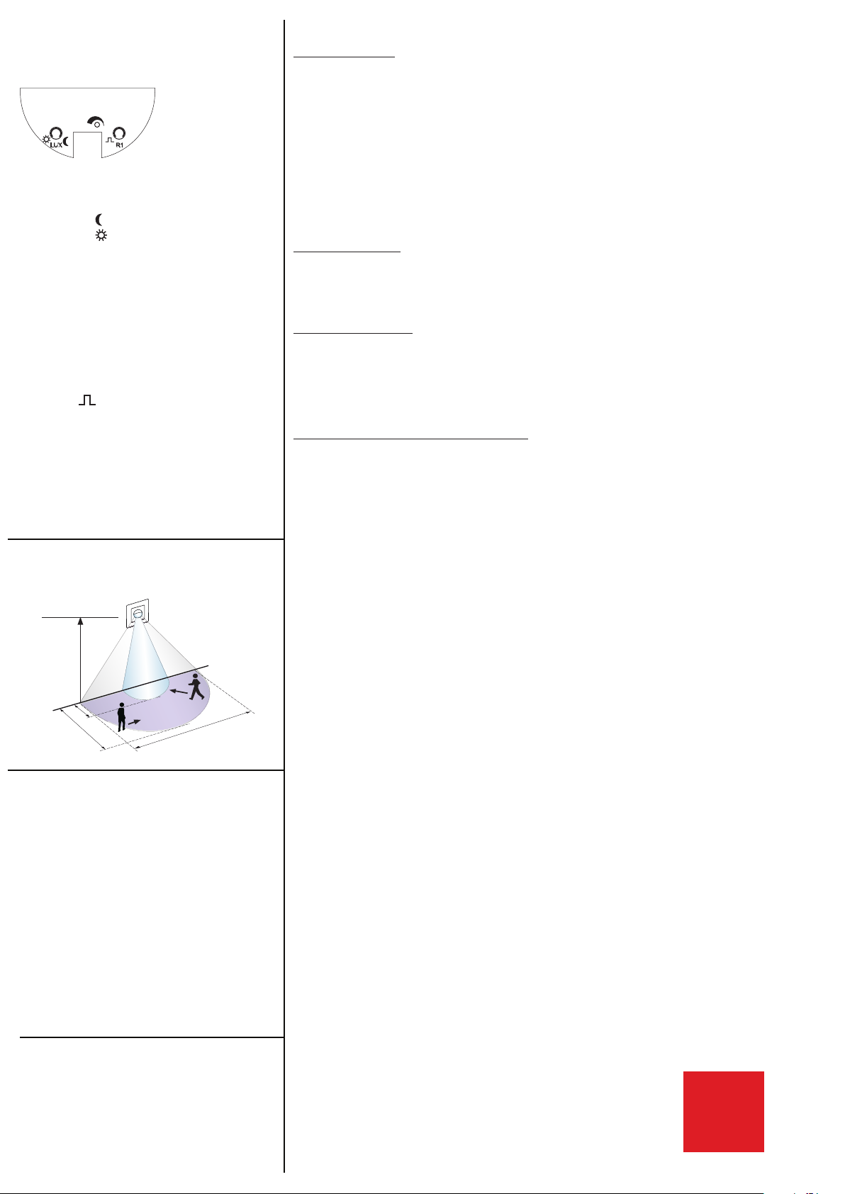
Twilightswitch (LUX)
600
1200
200
Mic
2000
40
The twilight-level can be set between approx.
40 to 2000 Lux.
Symbol
Symbol
Timer (R1)
• The delay timer can be adjusted from
15sec to 16 min
• TEST:
Use this mode for setting up operation.
Every movement will cause relay to switch
ON for 1sec and than OFF again: walktest
LED-1 shows the current lux-level:
LED-1 = ON = bright
LED-1 = OFF = dark
• Symbol
Every motion will turn ON relay for 1 sec
followed by a pause.
(the next pulse can only occur after pause!)
In pulse mode , there is no need for MIC/
acoustic detection. The MIC-control has
therefor an alternative function, it determines
the duration of pause following a pulse:
MIC-control = min = 9 sec
MIC-control = 50% = 30 sec
MIC-control = max = 60sec
2
1
5
30
10
16
15
Tes
: Night operation (dark only)
Day and night operation
Pulse/chime function.
Fig.5
8. Trouble shooting - Practical hints
1. Lamp does not light up
Cause:
Action:
Tungsten halogen lamp defective
- Replace tungsten halogen lamp
No mains connection
- Check connection by qualifi ed electrician
Incorrect setting of lux level
- Correct setting of lux level
Unit mounted too high
- Mount at recommended height
PIR detector lens obstructed by dirt or other objects
- Clean lens or remove objects
Main fuse defective
- Check or replace by qualifi ed electrician
2. Delayed lamp activation
Mounted too high
- Mount at height stated in specifi cation
(1.2 to 2.2m)
Direct line of approach
- Re-direct walking so that the approach is not frontally
3. Lamp stays on continuously
Continual thermal activity detected ie. extractor fan, central
heating ducts
- Check for any activity which could cause unit detection to be
maintained
Delay time set too high
- Reduce time delay
- Check ambient noiselevel, if necessary switch off noisesources
4. Limitation of range (not up to the minimum speci cation)
Mounted too high
- Correct mounting height
Temperature difference between ambient temperature and
source of heat too small
No improvement possible
Direction of movement aimed directly at lens of motion detector
Move laterally to detector
5. Wiring diagrams:
1.10 - 2.20 m
3 m
10 m
180°
12 m
6. Technical data
• Supply voltage 230 VAC ±10%
•
Accu 6 x NiMH/ 30 AAAAH
1,2V/300 mAh
• Detection angle 180° horizontally
approx. 60° vertically
• Range max. in m across 10.00 m
• Switching power
Ohmic load 3000W, cosϕ= 1
Inductive load 1500VA, cosϕ= 0.5
Electronic ballast 35x 36W
• Time settings 15sec to 16 min
or Impuls
• Twiglight switch 5 - 2000 Lux
• Dimensions LxW 87mm x 87 mm
Depth 61mm
• Ambient temperature: +5°C to +45°C
• Protection / class IP 20 / II / CE
• Enclosure material Housing of high grade UV- and
• Minimum Load 50W
shock-resistant Polycarbonate
7. Electromagnetic Compliance (EMV)
When positioned within direct vicinity of high powered radio
transmitting equipment (e.g. portable phones , H.A.M., taxi,
police, re, ambulance radio operators etc.) false activation
switching may be experienced. However, this in uence will not
damage the sensor electronics.
The automatic switching of the sensor will sease as soon as the
source of radio interference stops transmitting.
B.E.G.
MAN 6940 – 100214-2
 Loading...