

Page 1

Bedrock Secure OSA® Remote
User Manual
Page 2

Page 3

Contents
Contents
Disclaimer.......................................................................... v
Bedrock Secure OSA Remote Overview ................................ 1
Introduction.............................................................................................................1
OSA Remote Offerings...........................................................................................1
OSA Remote Features.............................................................................................1
Bedrock Secure OSA Remote Architecture.........................................................4
Security .....................................................................................................................6
Environmental.........................................................................................................7
Software Requirements...........................................................................................7
Connectivity.............................................................................................................7
OSA Remote Ethernet Connections............................................................................7
OSA Remote I/O Connections to Field Devices .........................................................8
Terminal Blocks...................................................................................................8
Bedrock Universal Cable.....................................................................................8
Bedrock UTAs .....................................................................................................8
Serial Port Connections...............................................................................................8
CAN I/O Port Connections.........................................................................................9
OSA Remote Operation..................................................... 10
OSA Remote Power Input....................................................................................10
OSA Remote Controller.......................................................................................10
Customer-specific OPC UA Security Keys................................................................11
Secure OPC UA Configuration.........................................................................11
Secure Boot Software.................................................................................................12
MRAM and Data Persistence...................................................................................12
IP Stack......................................................................................................................12
Ethernet Communication .........................................................................................13
OPC UA.....................................................................................................................13
Analog and Discrete Input/Output.....................................................................13
Operating Modes .......................................................................................................13
Simplified Circuit Diagram.......................................................................................14
Analog Data Format .................................................................................................14
Analog Accuracy Specifications ................................................................................15
HART Revision 7.......................................................................................................15
Discrete Output Switches ..........................................................................................15
Electronic Fusing .......................................................................................................15
Discrete Outputs........................................................................................................15
Discrete Output Accuracy.........................................................................................16
Recommended Practices............................................................................................17
Frequency Measurement / Pulse Accumulation.......................................................17
NAMUR.....................................................................................................................17
0-10 V Voltage Input .................................................................................................18
Software Configurable Options.................................................................................18
Wiring the Module ....................................................................................................18
10/11/18 Bedrock Secure OSA Remote User Manual - BRDOC020_001 i
Page 4

Contents
Module Fault and Status Indication.........................................................................18
Serial I/O ................................................................................................................18
Hardware Installation ...................................................... 20
Important User Information................................................................................20
Hazardous Location Information.............................................................................20
Environment and Enclosure......................................................................................20
Preventing Electric Static Discharge .........................................................................21
Safety-Related Programmable Electronic Systems ...................................................21
Optical Ports..............................................................................................................21
OSA Remote Installation......................................................................................21
Mounting the OSA Remote .................................................................................22
OSA Remote Power Input....................................................................................23
Ethernet Port Connections ..................................................................................25
OSA Remote I/O Connections............................................................................26
Cabling for Serial and CAN Bus Connections..................................................27
Software Configuration ..................................................... 28
Analog and Discrete
I/O Parameters.......................................................................................................28
Voltage Input Levels and Thresholds ........................................................................30
Input Options and Sensor Types ...............................................................................30
Line Frequency Options ............................................................................................30
Analog to Digital Sampling Rates.............................................................................30
I/O Update Rate ........................................................................................................31
Over Range Detection ...............................................................................................31
Fail-safe Output Feature ...........................................................................................31
Digital Mode of Operation........................................................................................32
Debounce Filter .........................................................................................................32
Overcurrent Retry .....................................................................................................33
Analog and Discrete
I/O Mapped Variables...........................................................................................33
Serial Port Parameters ..........................................................................................35
Serial Port Mapped Variables ..............................................................................37
CAN Bus I/O Parameters.....................................................................................37
CAN Bus Mapped Variables ................................................................................38
HART Devices .......................................................................................................38
HART Device Configuration.............................................. 39
Overview ................................................................................................................39
Intended Audience ................................................................................................39
HART Communication Protocol........................................................................39
Bedrock Field Device Tool ...................................................................................39
Prerequisite for Custom Certificates.........................................................................39
DTMs.........................................................................................................................40
ii Bedrock Secure OSA Remote User Manual - BRDOC020_001 10/11/18
Page 5

Contents
Software Components ..........................................................................................40
Configuring OSA Remotes with HART Devices ..............................................40
Common Functions..............................................................................................52
Topology Tab..............................................................................................................52
Import from XML.............................................................................................52
Export to XML..................................................................................................52
Scan and Create ................................................................................................52
Scan and Select..................................................................................................53
Update Catalogue .............................................................................................53
Device Tab .................................................................................................................53
Connect .............................................................................................................53
Disconnect.........................................................................................................53
Load from Device..............................................................................................53
Store to Device ..................................................................................................53
Set Offline Parameter .......................................................................................53
Set Online Parameter........................................................................................54
Configuration....................................................................................................54
Observe..............................................................................................................54
Diagnosis...........................................................................................................54
Monitoring and Troubleshooting ........................................ 56
Overview ................................................................................................................56
Troubleshooting Flowchart........................................................................................56
General Troubleshooting Tasks .................................................................................56
Built-in Self Test ....................................................................................................57
OSA Remote LEDs................................................................................................57
Status LED.................................................................................................................58
Ethernet LEDs ...........................................................................................................58
Cyber LED .................................................................................................................59
Channel LEDs............................................................................................................60
Storing Log Data in a Database...........................................................................60
Default Configuration...............................................................................................61
ODBC Database Setup and Configuration..............................................................62
Logging Service Execution ........................................................................................64
Copying OSA Remote Log Files..........................................................................67
Status Information.................................................................................................69
Part Numbers..........................................................................A-1
Wiring Diagrams and Pin Out Information..........................B-1
I/O Connector Pin Outs.........................................................................................1
I/O Connector Wiring Diagrams ..........................................................................5
Serial Port Wiring..................................................................................................10
CAN Bus Port Wiring...........................................................................................11
10/11/18 Bedrock Secure OSA Remote User Manual - BRDOC020_001 iii
Page 6

Contents
OSA Remote Specifications.....................................................C-1
General Specifications ............................................................................................1
Physical Characteristics...............................................................................................3
Field Wiring Requirements....................................................................................3
Input / Output Specifications ................................................................................3
Power Specifications ...............................................................................................7
HART Variables ..................................................................... D-1
Log Messages ...........................................................................E-1
Certifications and Standards.................................................. F-1
Certifications ...........................................................................................................1
Underwriters Laboratories (UL) Safety Compliance .................................................1
CE Testing....................................................................................................................1
IEC Environmental Testing.........................................................................................1
EIA Publication 364 ....................................................................................................2
FCC Testing .................................................................................................................3
Standards..................................................................................................................3
IEC 61131 ....................................................................................................................3
Acronyms................................................................................ G-1
iv Bedrock Secure OSA Remote User Manual - BRDOC020_001 10/11/18
Page 7

Disclaimer
Equipment, Diagrams, Hardware, and Software
Solid state equipment has operational characteristics differing from those of electromechanical equipment. Since there are a wide variety
of uses for solid state equipment, all persons responsible for applying this equipment must satisfy themselves that each intended
application of this equipment is acceptable. In no event will Bedrock Automation be responsible or liable for indirect or consequential
damages resulting from the use or application of this equipment.
The examples and diagrams in this manual are included solely for illustrative purposes. Because of the many variables and requirements
associated with any particular installation, Bedrock Automation cannot assume responsibility or liability for actual use based on the
examples and diagrams.
No patent liability is assumed by Bedrock Automation with respect to use of information, circuits, equipment, or software described in
this manual.
Throughout this manual, when necessary, we use notes to make you aware of safety considerations.
No Warranties
This manual is provided “as is” without any representations or warranties, express or implied. Bedrock Automation makes no
representations or warranties in relation to this manual or the information and materials provided herein. Although we make a reasonable
effort to include accurate and up to date information, without prejudice to the generality of this paragraph, Bedrock Automation does
not warrant that:
• The information in this manual is complete, true, accurate or non-misleading.
The Bedrock Secure OSA Remote User Manual is provided solely for informational purposes. You should not act upon information
without consulting Bedrock Automation.
Subject to Change
The Bedrock Secure OSA Remote User Manual is subject to change without notice.
Exceptions
Nothing in this disclaimer will exclude or limit any warranty implied by law that it would be unlawful to exclude or limit; and nothing in
this disclaimer will exclude or limit Bedrock Automation’s liability in respect of any:
• death or personal injury caused by Bedrock Automation’s negligence;
• fraud or fraudulent misrepresentation on the part of Bedrock Automation; or
• matter which it would be illegal or unlawful for
limit, its liability.
Bedrock Automation
to exclude or limit, or to attempt or purport to exclude or
Reasonableness
By using this manual, you agree that the exclusions and limitations of liability set out in this disclaimer are reasonable. If you do not
think they are reasonable, you must not use this manual.
Other Parties
You accept that, Bedrock Automation has an interest in limiting the personal liability of its officers and employees. You agree that you
will not bring any claim personally against Bedrock Automation’s officers or employees in respect of any losses you suffer in connection
with the manual.
Unenforceable Provisions
If any provision of this disclaimer is, or is found to be, unenforceable under applicable law, that will not affect the enforceability of the
other provisions of this disclaimer.
Manual Reproduction
Reproduction of the contents of this manual, in whole or in part, without written permission of Bedrock Automation, is prohibited.
10/11/18 Bedrock Secure OSA Remote User Manual - BRDOC020_001 v
Page 8

Page 9
Chapter 1
Bedrock Secure OSA Remote Overview
Introduction This document provides reference information for the Bedrock Secure OSA
Remote. This includes descriptions of OSA Remote hardware and software
components, configuration information, communications, and installation.
The OSA Remote is designed to provide remote applications with power,
control, and I/O in a single transportable unit that can be configured and
programmed on a desktop and then mounted at a remote location.
Each OSA Remote provides either ten or twenty universal, secure input/output
channels. Each channel has channel-to-channel and channel-to-ground galvanic
isolation. Each channel on the OSA Remote can be independently configured to
operate in one of several modes. Depending upon the mode selected, OSA
Remote channels can interface to analog inputs and outputs with or without
HART, discrete inputs and outputs, or NAMUR sensors. The available
operating modes are listed in the next section. Additional detail is provided in
“Analog and Discrete Input/Output”.
OSA Remote Offerings Both ten and twenty channel OSA Remote models are available with a standard
8 GB of flash memory or an optional 32 GB of flash memory. Table 1-1 lists the
available OSA Remote models. Customer-specific OPC UA security keys are
available for all models via a firmware upgrade. See “Customer-specific OPC UA
Security Keys” in “OSA Remote Operation”.
See Appendix A for part numbers for all OSA Remote models.
Table 1-1 OSA Remote Models
Model Name
R10.8 10 8 GB
R10.32 10 32 GB
R20.8 20 8 GB
R20.32 20 32 GB
No. of Universal
I/O Channels
Flash Memory
OSA Remote Features Bedrock Secure OSA Remotes include the following features:
• A microcontroller with an RTOS for managing control and
communications.
• Two models are available to provide ten (R10 models) or twenty (R20
models) input/output channels. The channels are galvanically isolated
from each other and from ground. The OSA Remote features ten or
twenty independent HART 7 modems. Each channel can be
10/11/18 Bedrock Secure OSA Remote User Manual - BRDOC020_001 1
Page 10

Chapter 1 Bedrock Secure OSA Remote Overview
independently configured to operate in one of the following modes.
See “Analog and Discrete Input/Output” in “OSA Remote
Operation” for more information.
• 4-20 mA input (loop current max. of 25 mA) with HART
• 4-20 mA output with readback with HART
• 4-20 mA input (loop current max. of 25 mA) without HART
• 4-20 mA output with readback without HART
• internally powered discrete output with readback (24 V
• externally powered discrete output with readback (maximum
•NAMUR
• 0-10 V voltage input
excitation, maximum current of 25 mA)
current of 1 amp)
• discrete input
• Power to the OSA Remote is provided by a 9-30 V DC input.
• Two Ethernet ports for connection to a Bedrock Control System
workstation via a local intranet and to third party devices.
• A serial port that provides RS-232, RS-485, or RS-422
communication to third party devices.
• A CAN bus port provides an interface to CAN devices.
• LEDs provide information on status, authentication, security, and
communication (Ethernet, serial, CAN). See “OSA Remote LEDs”
in “Monitoring and Troubleshooting”.
• Advanced security features include encryption, authentication, and
compliance with industry standards.
• OPC UA support for connectivity to external devices, HMIs, and
SCADA systems.
2 Bedrock Secure OSA Remote User Manual - BRDOC020_001 10/11/18
Page 11
Bedrock Secure OSA Remote Overview Chapter 1
137 mm
226 mm
46 mm
59 mm
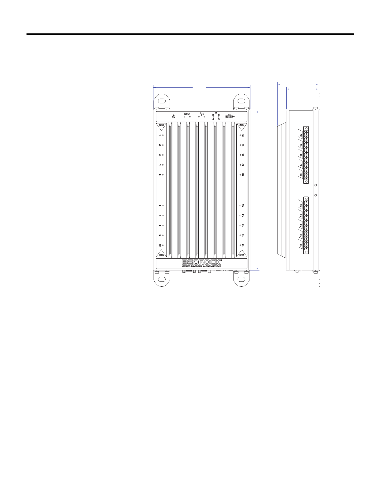
A dimensional diagram of an OSA Remote is shown in Figure 1-1. Each side of
the OSA Remote has two of the four twenty-pin I/O connectors.
Figure 1-1 OSA Remote with Dimensions
10/11/18 Bedrock Secure OSA Remote User Manual - BRDOC020_001 3
Page 12
Chapter 1 Bedrock Secure OSA Remote Overview
DC Power In
Serial Connection
CAN bus Connection
Ethernet Ports
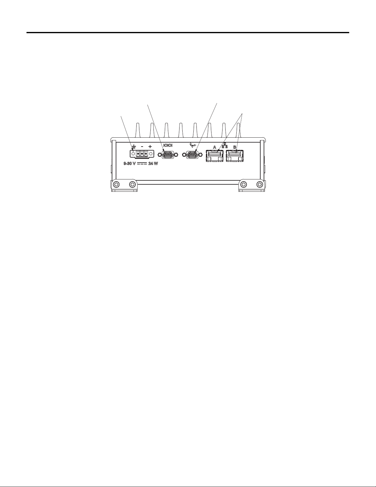
The bottom of the OSA Remote has connectors and ports for power, serial and
CAN bus communication, and Ethernet connections. These are shown in
Figure 1-2.
Bedrock Secure OSA Remote Architecture
Figure 1-2 OSA Remote Bottom View
The advanced design features of the OSA Remote architecture provide:
• Maximized throughput of sensor data
• Accurate timekeeping and coordination with super-capacitor backed
real-time clock
• High-speed control loops
• A more secure and robust system through the choice of:
• Point-to-point I/O communication
• Real-Time Operating System (RTOS)
• Active encryption security.
4 Bedrock Secure OSA Remote User Manual - BRDOC020_001 10/11/18
Page 13
Bedrock Secure OSA Remote Overview Chapter 1
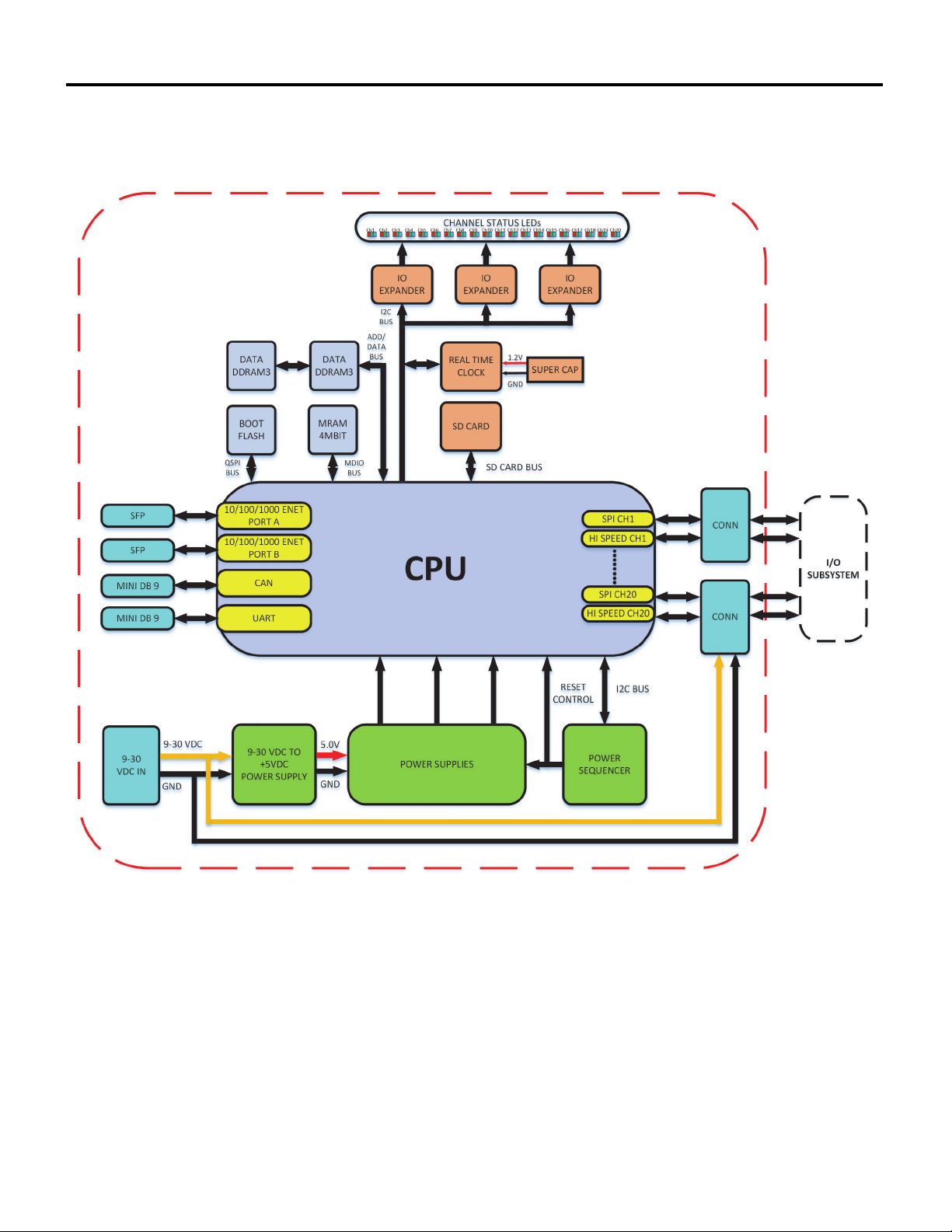
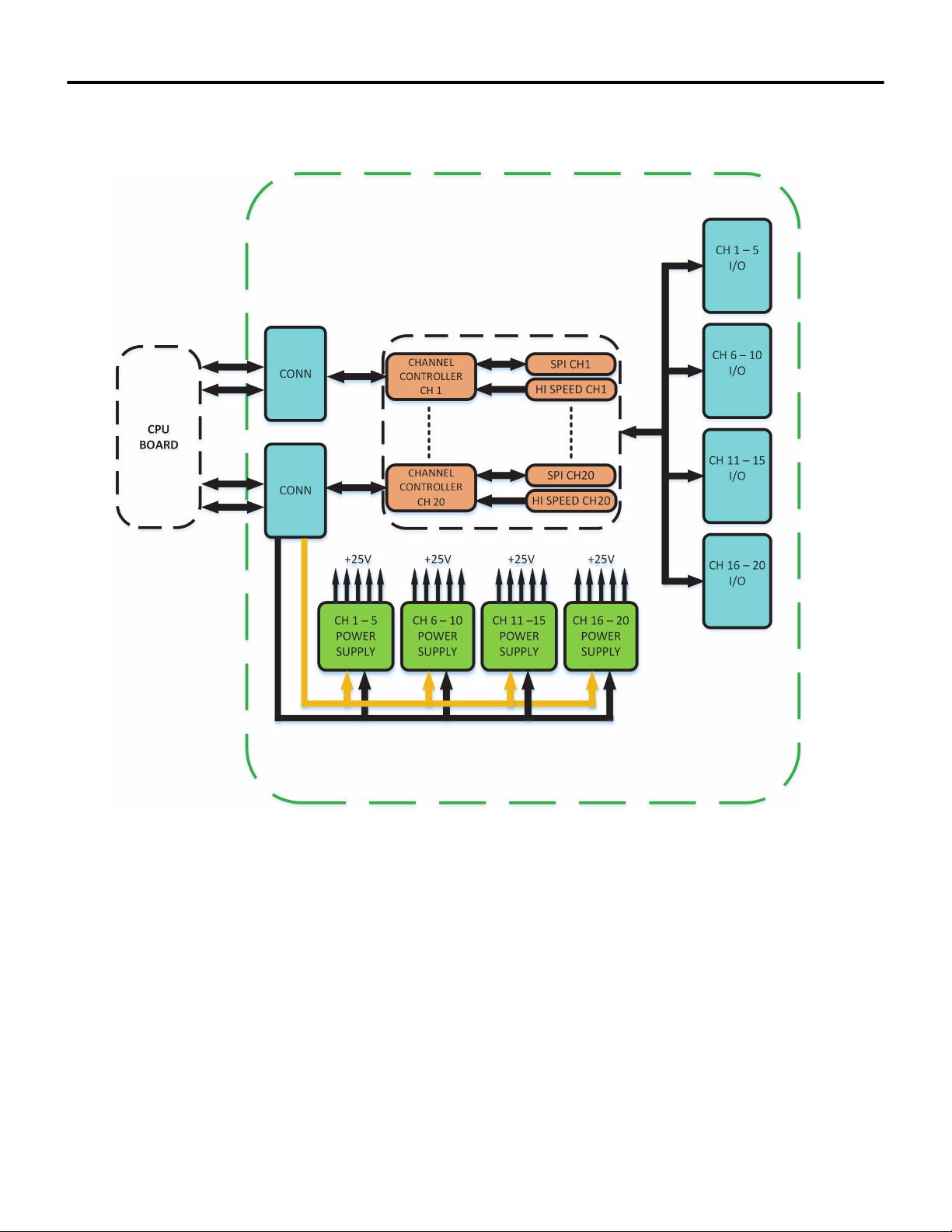
A block diagram of the Bedrock Secure OSA Remote CPU board is shown in
Figure 1-3. Figure 1-4 shows the I/O subsystem.
Figure 1-3 OSA Remote CPU Board Diagram
10/11/18 Bedrock Secure OSA Remote User Manual - BRDOC020_001 5
Page 14
Chapter 1 Bedrock Secure OSA Remote Overview
Figure 1-4 OSA Remote I/O Subsystem
Security The OSA Remote is designed with the security features listed below:
• Secure boot including an encrypted and signed image
• Transport Layer Security (TLS) with X.509 certificates used on all
workstation communication channels
• Certificates and cryptographic keys with a usable lifetime projected
beyond the year 2030
6 Bedrock Secure OSA Remote User Manual - BRDOC020_001 10/11/18
Page 15

Bedrock Secure OSA Remote Overview Chapter 1
• Image updates that are signed and encrypted and will be rejected if
they fail authentication
• True random number generator
• Physical tamper protection that is designed for compliance with
FIPS 140-2 Level 2
• Designed to meet ISASecure Level 3 for Devices
• Compliance with NIST SP800-57, Recommendation for Key
Management
• Compliance with FIPS 186-4, Digital Signature Standard
Environmental The following are the environmental conditions applicable to the OSA Remote.
• -40°C to +80°C operating temperature
• -40°C to +85°C storage temperature
• 5% to 95% non-condensing humidity
Software
The following software is required for use with the OSA Remote.
Requirements
• the Bedrock Integrated Development Environment (IDE)
• the Bedrock Field Device Tool (FDT) for configuring the OSA
Remote to communicate with field devices that support the HART
Communication Protocol. See the “HART Device
Configuration”chapter for more information.
Connectivity The following are the requirements for OSA Remote communication
connections.
OSA Remote Ethernet Connections
Communication over OSA Remote Ethernet ports is via a small form-factor
pluggable (SFP) module. A Copper Ethernet SFP Interface Module is provided
and can be used with a Cat6 shielded copper cable to provide 10/100/1000
Mbps communication. An optional Fiber Ethernet SFP Interface Module can be
used with a fiber-optic cable to provide 1 Gbps Ethernet over fiber.
One Ethernet port is to be used for communication with the Bedrock Control
System workstation while the second is for user-defined applications. The
Ethernet ports must be configured to use different subnets.
10/11/18 Bedrock Secure OSA Remote User Manual - BRDOC020_001 7
Page 16

Chapter 1 Bedrock Secure OSA Remote Overview
OSA Remote I/O Connections to Field Devices
Bedrock Automation provides the options listed below for connecting OSA
Remotes to field devices.
Terminal Blocks
Twenty-pin pluggable terminal blocks are provided for connecting field devices
to the Bedrock Secure OSA Remote via a user-provided cable or the Bedrock
Universal Cable. See Appendix B for pin out information and wiring diagrams.
See Appendix C for field wiring requirements.
Bedrock Universal Cable
The Bedrock Universal Cable is available as an accessory for connecting the OSA
Remote to field devices. The cable is available in three fixed lengths as well as a
custom length as follows:
•1 meter
• 3 meters
• 5 meters
• the custom length cable is available in increments of one meter up to
a maximum length of 30 meters.
See Appendix A, “Part Numbers” for information on ordering the Bedrock
Universal Cable.
Bedrock UTAs
Bedrock Universal Termination Assemblies (UTAs) are DIN rail mounted screw
terminals that simplify connections between OSA Remotes and field devices.
The Bedrock Dual-head Universal Cable is used to make the connection
between an OSA Remote and a UTA. The dual-head cable, like the universal
cable, is available in lengths of 1, 3, and, 5 meters. It is also available in a custom
length.
See the Bedrock UTA User Manual for information on the Bedrock UTAs and
the dual-head universal cable.
Serial Port Connections The Bedrock Secure OSA Remote has a serial port for communication with
other devices that are capable of serial communication using the RS-232,
RS-485, or RS-422 protocols. The Bedrock Universal Serial Communication
Cable is available as an option for connecting the OSA Remote to other devices
via the serial port.
8 Bedrock Secure OSA Remote User Manual - BRDOC020_001 10/11/18
Page 17

Bedrock Secure OSA Remote Overview Chapter 1
See “Serial Port Wiring” in “Wiring Diagrams and Pin Out Information” for
serial port wiring information.
CAN I/O Port Connections A CAN I/O port is also provided to support CAN bus communication between
the OSA Remote and devices using the CAN bus protocol. The Bedrock
Universal Serial Communication Cable is available as an option for connecting
the OSA Remote to other devices via the CAN I/O port.
See “CAN Bus Port Wiring” in “Wiring Diagrams and Pin Out Information”
for wiring information for the CAN bus port.
10/11/18 Bedrock Secure OSA Remote User Manual - BRDOC020_001 9
Page 18

Chapter 2
OSA Remote Operation
The OSA Remote Operation section provides information that is specific to the
following OSA Remote functions:
• power input
• OSA Remote Controller
• analog and discrete I/O operating modes
• serial I/O
• CAN bus.
OSA Remote Power
Power is provided to the OSA Remote by a 9-30 V DC power source.
Input
Note
Note that the OSA Remote turns on at 10 V and will shut off below 9 V.
UL has designated the OSA Remote as a low voltage, limited current (LVLC)
source. UL recommends using a UL Listed Class 2 power supply for the
9-30 V DC input.
See “OSA Remote Power Input” in “Hardware Installation” for information on
power connections including cabling and pin outs.
OSA Remote Controller Bedrock Secure OSA Remotes feature a microcontroller that provides the
operating system, network communications, provisions for hardware
configuration, and management of system operations. The OSA Remote
microcontroller scans inputs, executes control functions and writes outputs. It
also provides control and system status information to upper Ethernet systems,
e.g., a workstation.
The OSA Remote microcontroller includes the following features:
• 512 MB of RAM
• 8 kB of MRAM for storage of persistent and retain variables
• standard 8 GB of flash memory for control applications with an optional
32 GB available
10 Bedrock Secure OSA Remote User Manual - BRDOC020_001 10/11/18
Page 19

OSA Remote Operation Chapter 2
• dual-mode IP stack
• OPC UA for connection to external devices
• customer-specific OPC UA security keys for increased security (see
below)
Customer-specific OPC UA Security Keys
Bedrock Automation provides customers with the option of ordering OSA
Remotes with OPC UA certificates for increased security. The OPC UA
certificates are standard X.509 certificates with required OPC UA fields and
must be issued by the Bedrock Certificate Authority. Customer-specific security
certificates can be added to OSA Remotes already in the field using the Bedrock
Upgrade Utility. The OPC UA communication protocol is required for
application software to securely communicate with OSA Remotes using
customer-specific security certificates. As a result, the Bedrock IDE and any
additional OPC UA client software must also be updated with the appropriate
security certificates.
An OPC UA server certificate is required to be loaded onto any OSA Remote
that is being upgraded. A separate client certificate is required for any OPC UA
client software to be able to connect to a OSA Remote that is configured with
customer-specific security certificates. OPC UA client certificates are specific to
each OPC UA client application.
Contact Bedrock Automation for guidance on upgrading OSA Remotes and
configuring software with customer-specific security certificates. For OSA
Remotes, you will need to provide the OSA Remote name or IPv4 address.
OSA Remote names must start with a letter and contain only letters and
numbers without dashes or underscores. Any changes to information that is
embedded in the certificate, e.g., OSA Remote name or IPv4 address, will
require a new OPC UA server certificate.
Part numbers for ordering the firmware upgrade for customer-specific security
certificates for OSA Remotes are listed in Table A-1.
See the Bedrock IDE online help for information on the Bedrock Upgrade
Utility.
Secure OPC UA Configuration
Secure OPC UA is configured using parameters in the Bedrock IDE. The
parameters can be accessed by opening an OSA Remote editor and selecting the
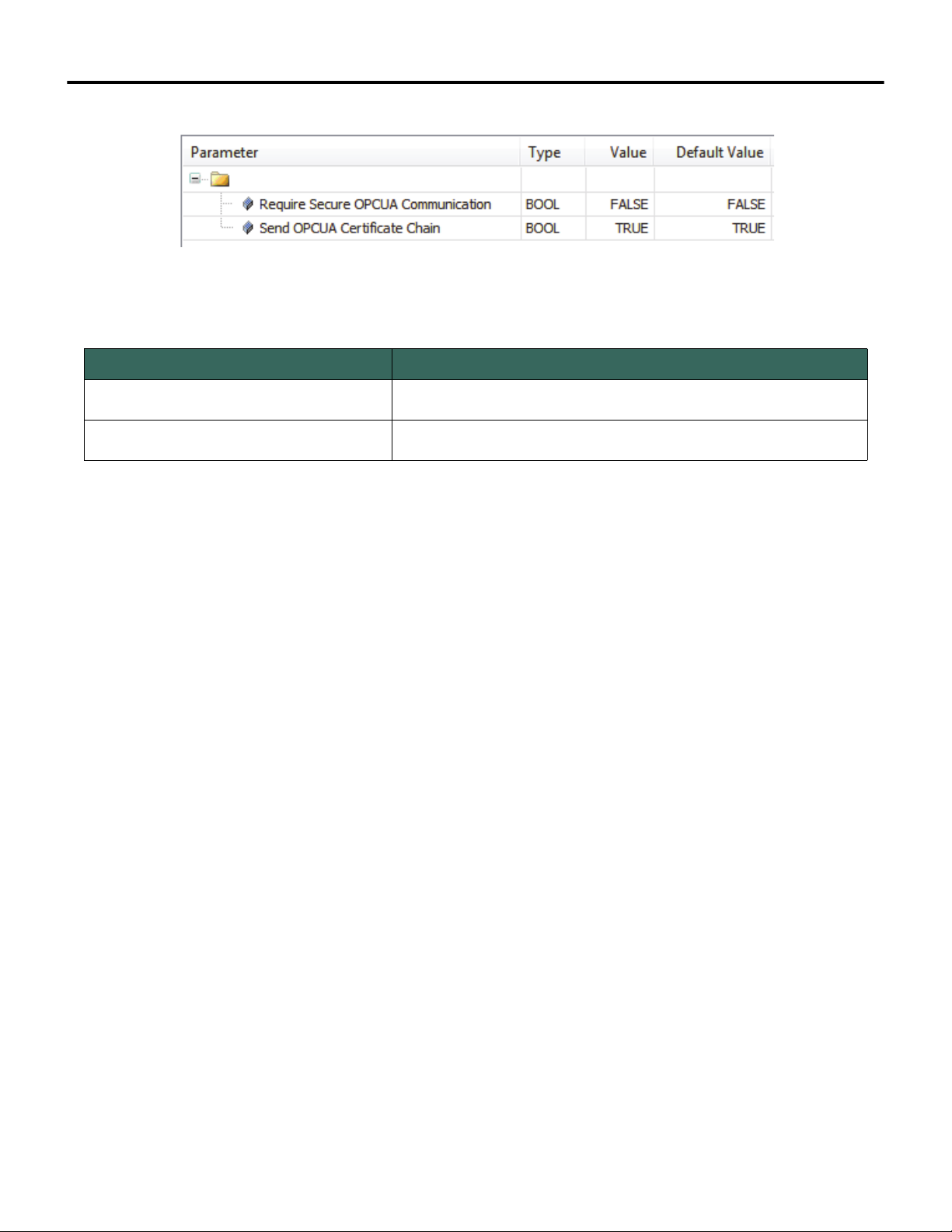
OPC UA Security Parameters tab. The parameters are shown in Figure 2-1 and
described in Table 2-1.
10/11/18 Bedrock Secure OSA Remote User Manual - BRDOC020_001 11
Page 20
Chapter 2 OSA Remote Operation
Figure 2-1 Secure OPC UA Parameters in the Bedrock IDE
Table 2-1 Parameters for Configuration of Secure OPC UA
Parameter Name Description
Require Secure OPC UA Communication
Send OPC UA Certificate Chain
Set to TRUE to require Secure OPC UA. Set to FALSE to make Secure
OPC UA optional, i.e. Secure OPC UA is allowed but not required.
If set to TRUE, the entire certificate chain is sent from the OSA Remote to
the client. If set to FALSE, just the certificate itself is sent..
Secure Boot Software This software component manages power on startup. It is responsible for
initializing the hardware and starting the operating system.
MRAM and Data Persistence
The Bedrock Secure OSA Remote has 8 kB of magnetoresistive RAM (MRAM)
available. This allows control programs to have access to persistent or retained
variables. These two types of variables are declared in Program Organization
Units (POUs) in the Bedrock IDE and provide data persistence as follows:
• Persistent variables are restored after cold resets, warm resets, or
program downloads. They are cleared using the Reset Origin function
in the Bedrock IDE.
• Retain variables are restored after a warm reset. They are cleared using
the Reset Origin function in the Bedrock IDE.
Refer to the Bedrock IDE online help for information on how to implement
persistent and retained variables in your application.
Note that an application program in the Bedrock IDE must have its task
interval set to 5 ms or greater to ensure that the MRAM is correctly updated
during each control cycle.
IP Stack Bedrock Secure OSA Remotes use a dual-mode IPv4/IPv6 stack.
12 Bedrock Secure OSA Remote User Manual - BRDOC020_001 10/11/18
Page 21

OSA Remote Operation Chapter 2
Ethernet Communication OSA Remote Ethernet communication is designed to interface to a local intranet
through one of its Ethernet ports. A second Ethernet port is available for user
applications. The two Ethernet ports must be configured to be on separate
subnets.
A Copper Ethernet SFP Interface Module is provided and can be used with a
Cat6 shielded copper cable to provide 10/100/1000 Mbps communication. An
optional Fiber Ethernet SFP can be used with a fiber-optic cable to provide 1
Gbps Ethernet over fiber.
OPC UA The OSA Remote software uses the OPC Unified Architecture communication
protocol for connectivity to external devices, HMIs, and SCADA systems.
For more information about OPC UA, visit the OPC foundation website at:
https://opcfoundation.org/
Analog and Discrete Input/Output
Each universal I/O channel on an OSA Remote can be independently configured
to operate in one of several modes. Depending upon the mode selected, OSA
Remote channels can interface to analog inputs and outputs with or without
HART, discrete inputs and outputs, or NAMUR sensors.
Operating Modes The operating modes of the OSA Remote are listed below. These modes are
selected using the Bedrock IDE.
• 4-20 mA input (loop current max. of 25 mA) with HART
• 4-20 mA output with readback with HART
• 4-20 mA input (loop current max. of 25 mA) without HART
• 4-20 mA output with readback without HART
• internally powered discrete output with readback (24 V excitation,
maximum current of 25 mA)
• externally powered discrete output with readback (maximum current of
1amp)
•NAMUR
• 0-10 V voltage input
• discrete input
OSA Remote channels may also be set to “Spare” in the Bedrock IDE for
configurations where a channel is not being used.
10/11/18 Bedrock Secure OSA Remote User Manual - BRDOC020_001 13
Page 22
Chapter 2 OSA Remote Operation
Note the following regarding the OSA Remote operating modes:
• When configured for 4-20 mA outputs, the readback value shown in
the Bedrock IDE will not change unless there is a connected load.
• Discrete outputs can be used to readback current up to 1 amp.
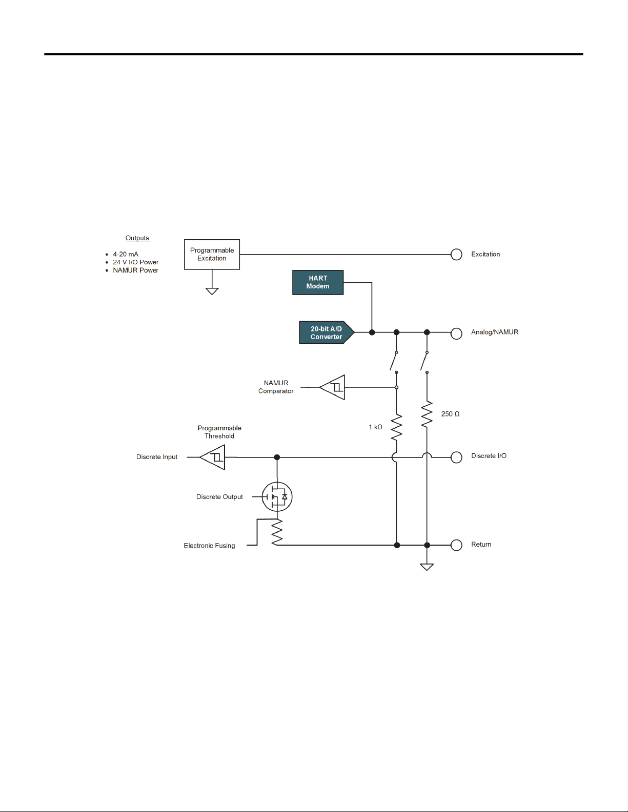
Simplified Circuit Diagram Figure 2-2 shows a simplified circuit diagram of an OSA Remote I/O channel.
Figure 2-2 OSA Remote Simplified Circuit Diagram
Analog Data Format The analog data is 32-bit floating-point IEEE-754 format.
14 Bedrock Secure OSA Remote User Manual - BRDOC020_001 10/11/18
Page 23

OSA Remote Operation Chapter 2
Analog Accuracy Specifications
See Table C-3 for information on the following OSA Remote analog accuracy
specifications:
• analog input accuracy for 4-20 mA inputs
• analog input accuracy for 10 V inputs (0-10 V)
• analog output accuracy
• temperature coefficient
HART Revision 7 The OSA Remote can communicate to smart field devices using the HART
Communication Protocol. The module is a HART master device and supports
HART Revision 7 software. See the “HART Device Configuration” chapter for
information on configuration of HART devices with OSA Remotes.
Discrete Output Switches The output switch consists of a high-powered MOSFET capable of switching up
to 1 amp at 30 V DC.
Electronic Fusing When configured for discrete output, a channel can utilize an electronic fuse that
will disable the channel if the current exceeds a programmable threshold up to
1 amp. Each channel’s electronic fuse can be configured to latch off or auto retry
during an overcurrent condition. When the channel has been latched off, the
channel must be disabled (turned off) to clear the fault condition. Channel faults
can be detected in the Bedrock IDE by checking bit 4 of the Input Analog Status
mapped variable for a channel. See Table 4-7 and Table 4-8 for information on
mapped variables and status bit definitions.
Discrete Outputs When an OSA Remote channel is configured to operate as a discrete output, the
discrete output can be externally sourced or internally sourced. Internally
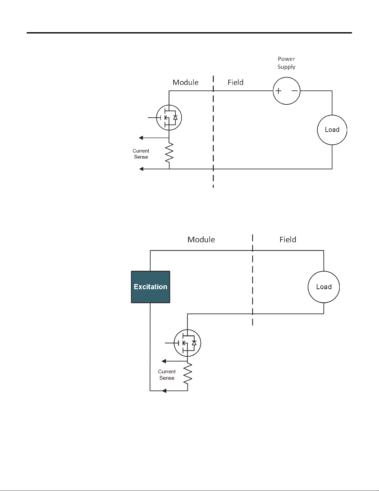
sourced discrete outputs are ideal for driving solid state relays. A circuit diagram
for an externally sourced discrete output is shown in Figure 2-3. A circuit
diagram for an internally sourced discrete output is shown in Figure 2-4.
10/11/18 Bedrock Secure OSA Remote User Manual - BRDOC020_001 15
Page 24
Chapter 2 OSA Remote Operation
Figure 2-3 Externally Sourced Discrete Output
Figure 2-4 Internally Sourced Discrete Output
Discrete Output Accuracy The discrete output current measurement is accurate to within 1.5% of full scale.
16 Bedrock Secure OSA Remote User Manual - BRDOC020_001 10/11/18
Page 25
OSA Remote Operation Chapter 2
Recommended Practices The following are recommended practices for use of the OSA Remote:
• External fusing is recommended for all discrete outputs.
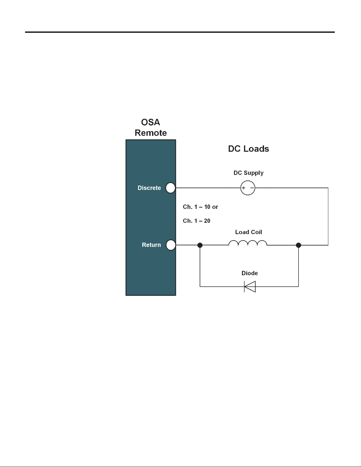
• External surge protection is required across the load for inductive loads
greater than 60 mH. A suppression circuit for DC loads is shown in
Figure 2-5.
Figure 2-5 OSA Remote Diode Suppression Circuit with DC Load
Frequency Measurement / Pulse Accumulation
Each discrete input channel is configurable for discrete on/off detection or the
channel can be used for frequency measurement from 10 Hz to 100 kHz. Each
channel can also be used for pulse accumulation. Up to 4 billion pulses can be
captured. Pulses are captured on falling edges.
NAMUR An OSA Remote can be configured to interface to a NAMUR output sensor.
The NAMUR sensor will provide a low-level current to the OSA Remote which
will use the current level to determine if the signal represents an on or off
condition or a sensor failure. NAMUR sensors are typically used in hazardous
environments. See Table C-8 for NAMUR specifications. Use the Mode
parameter in the Bedrock IDE to configure the OSA Remote for NAMUR.
10/11/18 Bedrock Secure OSA Remote User Manual - BRDOC020_001 17
Page 26
Chapter 2 OSA Remote Operation
0-10 V Voltage Input An OSA Remote can be configured to accept a 0-10 V analog input. This
configuration is set using the Mode parameter in the Bedrock IDE.
Software Configurable Options
Configurable parameters for analog and discrete I/O functions of OSA Remotes
are described in “Software Configuration”.
Wiring the Module See Appendix B, “Wiring Diagrams and Pin Out Information”for OSA Remote
wiring information.
Module Fault and Status Indication
See “OSA Remote LEDs” in “Monitoring and Troubleshooting” for the list of
blink codes used to indicate status for OSA Remotes.
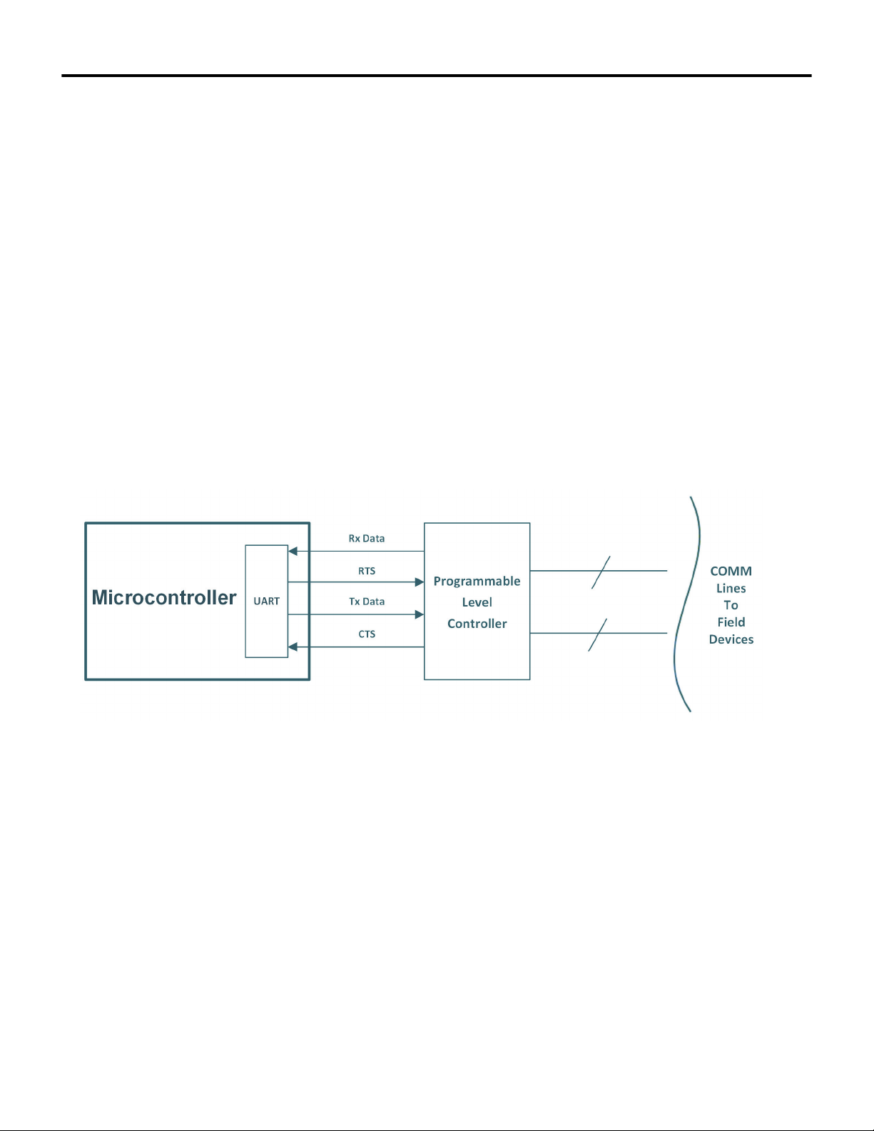
Serial I/O The OSA Remote serial channel has its own processor as shown in Figure 2-6.
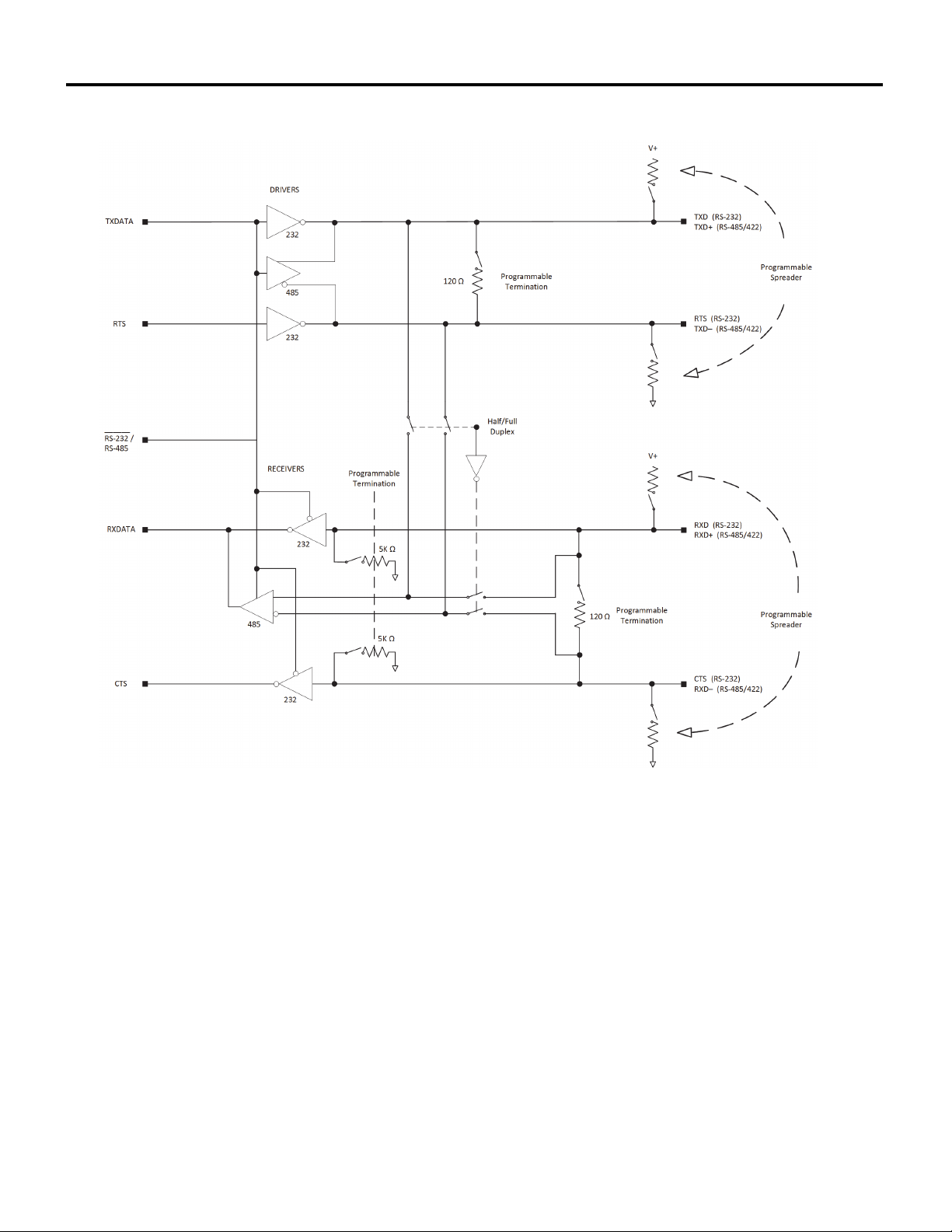
The Programmable Level Controller processes the transmit and receive data for
the supported serial communication standards.
Figure 2-6 OSA Remote Serial Channel
A circuit diagram of the Programmable Level Controller is shown in Figure 2-7.
18 Bedrock Secure OSA Remote User Manual - BRDOC020_001 10/11/18
Page 27
OSA Remote Operation Chapter 2
Figure 2-7 Programmable Level Controller
10/11/18 Bedrock Secure OSA Remote User Manual - BRDOC020_001 19
Page 28
Chapter 3
Hardware Installation
Important User Information
Hazardous Location Information
The section contains instructions to install the OSA Remote hardware. Read the
instructions and follow all warnings and notes prior to beginning installation.
Complete these tasks before you install the system.
• Verify that you have the components required to install your system.
• Read and understand the safety and environmental warnings and
considerations explained in the installation instructions.
WARNING
EXPLOSION HAZARD - DO NOT CONNECT OR DISCONNECT AN OSA REMOTE
WHILE IT IS ENERGIZED.
Environment and Enclosure
Important
Note the following with regard to installation of the Bedrock OSA Remote in
hazardous locations:
THE EQUIPMENT IS AN OPEN-TYPE DEVICE MEANT TO BE INSTALLED IN
AN ENCLOSURE SUITABLE FOR THE ENVIRONMENT AND THAT IS ONLY
ACCESSIBLE WITH THE USE OF A TOOL.
Important
When mounting an OSA Remote in an enclosure, the OSA Remote must be
mounted and grounded to a metal plate. Additionally, the enclosure must have
the following minimum dimensions:
50.80 cm (20 in.) W
60.96 cm (24 in.) H
20.32 cm (8 in.) D
20 Bedrock Secure OSA Remote User Manual - BRDOC020_001 10/11/18
Page 29
Preventing Electric Static Discharge
Hardware Installation Chapter 3
Note
This equipment is designed to be resistant to Electric Static Discharge (ESD) up
to 4 kV contact discharge and 8 kV air discharge in accordance with IEC
61000-4-2.
Note
Please be sure to keep original packaging including the anti-static bags to be
used for storage or shipping.
Safety-Related Programmable Electronic Systems
Optical Ports
Attention
Personnel responsible for the application of safety-related programmable
electronic systems (PES) shall be aware of the safety requirements in the
application of the system and shall be trained in use of the system.
Attention
Under certain conditions, viewing the optical port may expose the eye to
hazard. When viewed under some conditions, the optical port may expose the
eye beyond the maximum permissible-exposure recommendations.
Bedrock OSA Remotes are Class 1 laser products pursuant to FDA/CDRH and
EN (IEC) 60825 regulations. Laser radiation is present when the system is open.
Only trained and qualified personnel are allowed to install, replace or service
this equipment.
When not in use, covers should be in place.
OSA Remote Installation
The remainder of this section provides instructions for the following tasks
required for installation of the Bedrock Secure OSA Remote:
• mounting the OSA Remote on a sheet metal panel
10/11/18 Bedrock Secure OSA Remote User Manual - BRDOC020_001 21
Page 30
Chapter 3 Hardware Installation
• connecting the OSA Remote to a power source
• making Ethernet connections
• wiring the I/O connectors
• connecting to serial devices.
Mounting the OSA Remote
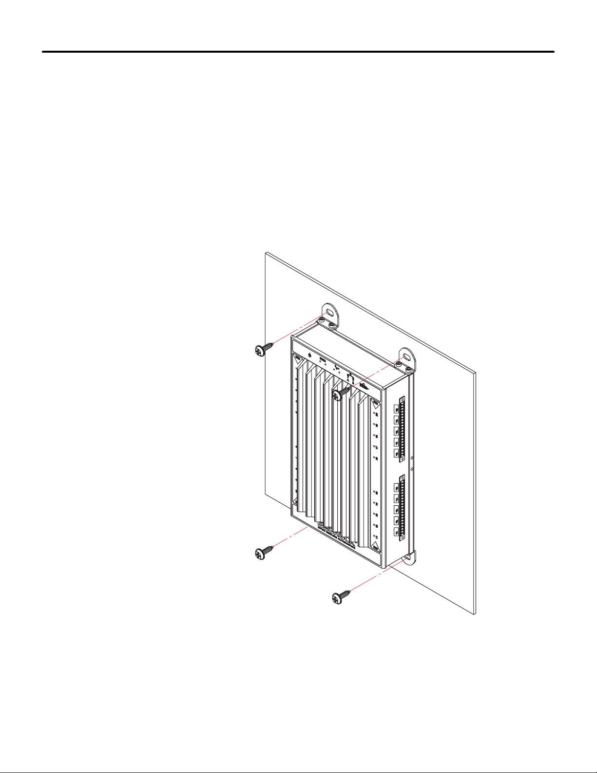
The Bedrock Secure OSA Remote can be mounted onto a sheet metal panel or
cabinet by inserting four #10 sheet metal screws through four right-angle
brackets that can be attached to the top and bottom of the
OSA Remote enclosure. See Figure 3-1.
Figure 3-1 OSA Remote Panel Mount
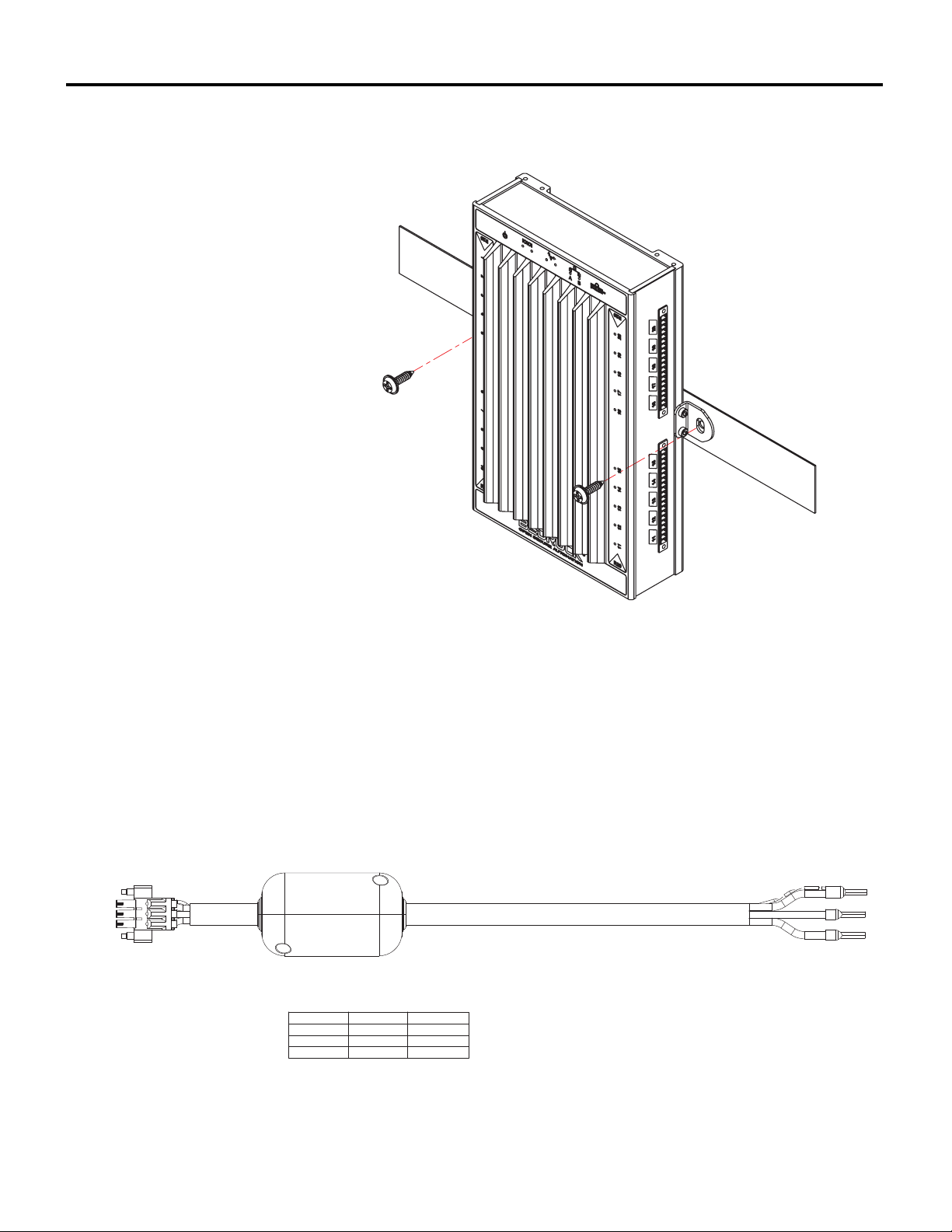
Alternatively, the Bedrock Secure OSA Remote can be mounted onto a DIN rail
by inserting two #10 sheet metal screws through two right-angle brackets that
22 Bedrock Secure OSA Remote User Manual - BRDOC020_001 10/11/18
Page 31
Hardware Installation Chapter 3
PIN 3
PIN 2
PIN 1
PIN NO.
COLOR
FUNCTON
PIN 3
GREEN
GROUND
PIN 2
BLACK
RETURN
PIN 1
RED
VOLTAGE IN
can be attached to the sides of the OSA Remote enclosure. See Figure 3-2.
OSA Remote Power Input
Figure 3-2 OSA Remote Rail Mount
The OSA Remote requires a 9-30 V DC power source. It is recommended that
SPM DC Input Power Cable from Bedrock Automation be used for providing
DC power to the OSA Remote. Alternatively, a user-provided cable may be used.
The SPM DC Input Power Cable and pin out information is shown in
Figure 3-3. Connect the drain wire to earth ground.
Figure 3-3 SPM DC Input Power Cable
10/11/18 Bedrock Secure OSA Remote User Manual - BRDOC020_001 23
Page 32
Chapter 3 Hardware Installation
DC Power In
Serial Connection
CAN bus Connection
Ethernet Ports
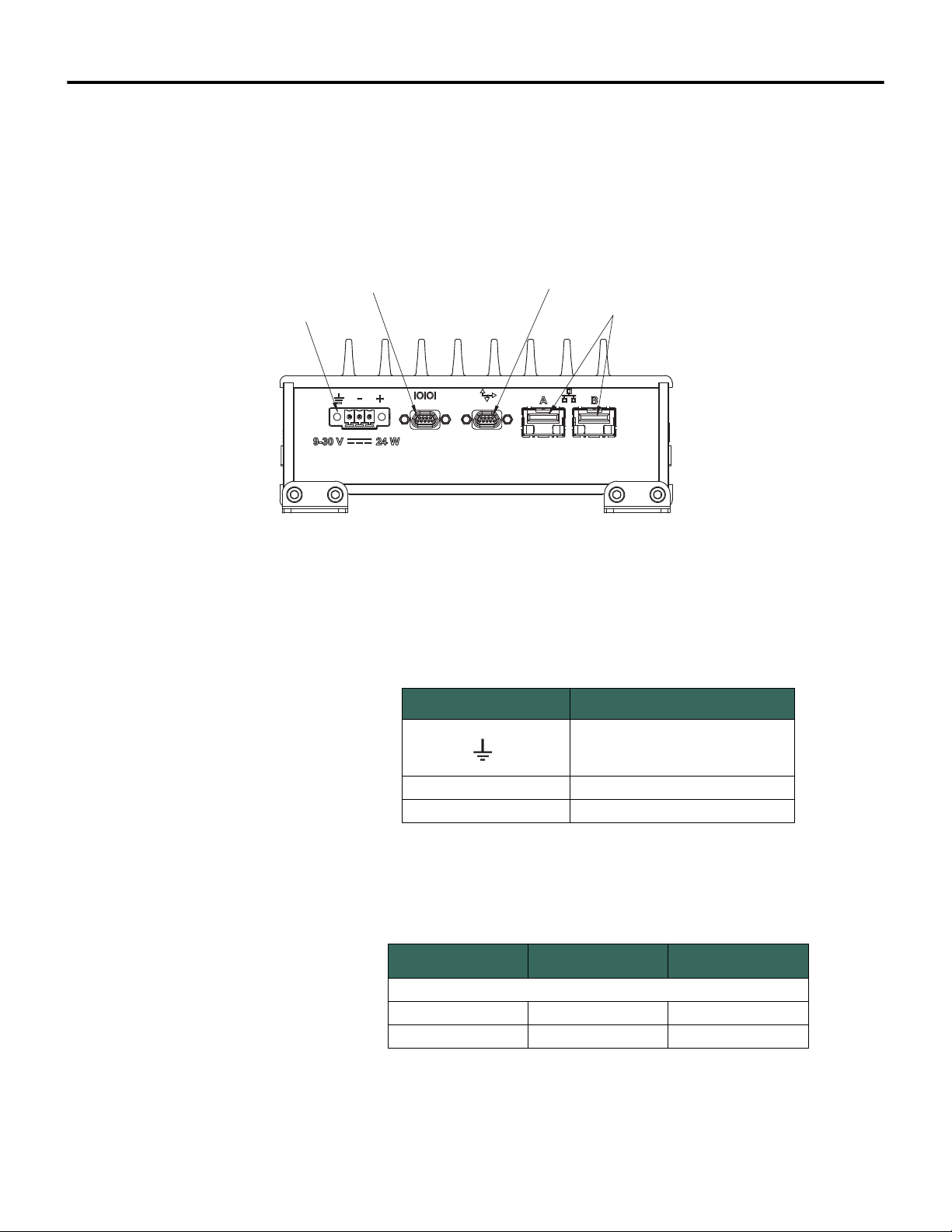
Power connections to the OSA Remote are made to the power three-pin power
connector on the bottom of the OSA Remote. The connector is shown in
Figure 3-4. UL recommends using a UL Listed Class2 power supply. A pair of
screws on each connector allow the connectors to be securely fastened to the
module.
Figure 3-4 OSA Remote Bottom View
Labels and functions of the three-pin power connectors are listed in Table 3-1.
Table 3-1 System Power Connector Pin Out
Label Function
Safety ground for system
- Power return
+ Power input
Table 3-2 lists the power input requirements.
Table 3-2 OSA Remote Power Input Requirements
Minimum Maximum
Input Voltage* 9 V 29.9 V
Input Power 25 W
DC Input
24 Bedrock Secure OSA Remote User Manual - BRDOC020_001 10/11/18
Page 33

Hardware Installation Chapter 3
Note
Note that the OSA Remote turns on at 10 V and will shut off below 9 V.
Ethernet Port Connections
Communication over the OSA Remote Ethernet ports is via a small form-factor
pluggable (SFP) module. A Copper Ethernet SFP Interface Module is provided
and can be used with a Cat6 shielded copper cable to provide 10/100/1000
Mbps communication. An optional Fiber Ethernet SFP Interface Module can be
used with a fiber-optic cable to provide 1 Gbps Ethernet over fiber.
Ethernet connections are made by connecting the copper or fiber-optic cable
from one of the RJ45 connectors (labeled A and B in Figure 3-4) to a
networked device such as a Bedrock Control System workstation.
The following are the Cat6 shielded copper cable specifications:
• 10/100/1000 Mbps
• full and half duplex communication
• 100 m maximum cable length
The following are the fiber-optic cable specifications:
• 9/125 μm single mode fiber (SMF)
• 1310 nm wavelength
• 1.25 Gbit bi-directional
• Up to 10 km range
OSA Remote I/O Connections
Connect the OSA Remote to field devices by using either a user-provided cable
or the Bedrock Universal Cable (available as an accessory). See “Field Wiring
Requirements” in Appendix C.
Important
Prior to connecting the cable, ensure that the temperature rating of the cable
adheres to the specifications listed in this document. See Field Wiring
10/11/18 Bedrock Secure OSA Remote User Manual - BRDOC020_001 25
Page 34
Chapter 3 Hardware Installation
Requirements in Appendix C, OSA Remote Specifications.
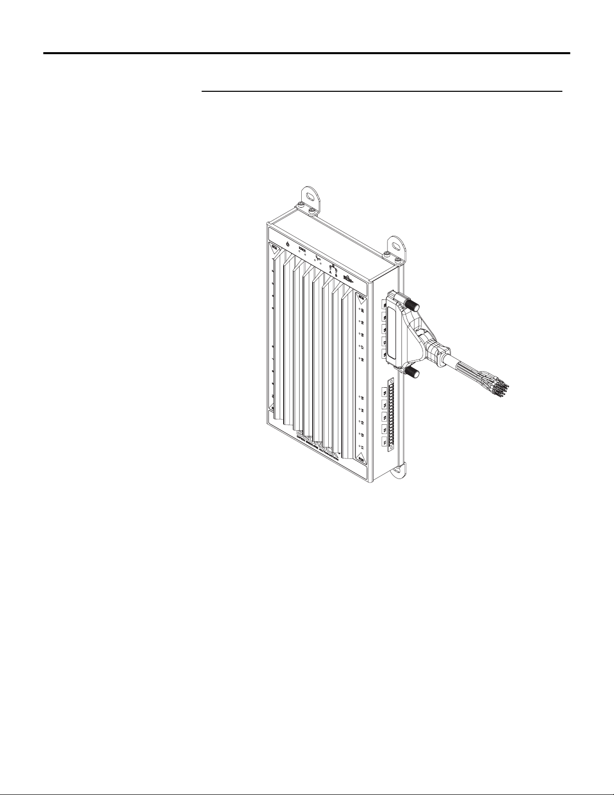
Thumb screws located on the cable assembly secure the assembly to the OSA
Remote twenty pin I/O connectors. Connect the assembly to the OSA Remote
as shown in Figure 3-5.
Figure 3-5 Bedrock Universal Cable Connected to OSA Remote
The wiring diagram and pin outs for the universal cable and OSA Remote
connectors are shown in Figure 3-6. Connect the drain wire to earth ground.
26 Bedrock Secure OSA Remote User Manual - BRDOC020_001 10/11/18
Page 35
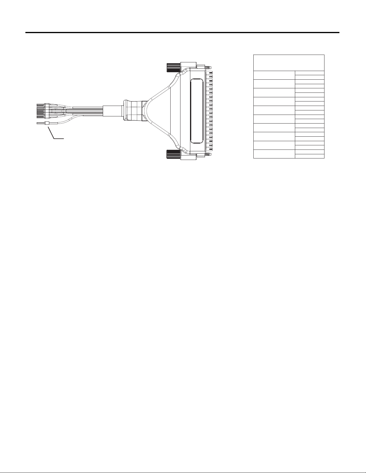
Figure 3-6 Universal Cable Pin Out Diagram
PIN 1
PIN 2
PIN 3
PIN 4
PIN 5
PIN 6
PIN 7
PIN 8
PIN 9
PIN 10
PIN 11
PIN 12
PIN 13
PIN 14
PIN 15
PIN 16
PIN 17
PIN 18
PIN 19
PIN 20
WIRING DIAGRAM FOR I/O
CONNECTIONS
PAIR 1
PIN 1
PIN 2
PAIR 2
PIN 3
PIN 4
PAIR 3
PIN 5
PIN 6
PAIR 4
PIN 7
PIN 8
PAIR 5
PIN 9
PIN 10
PAIR 6
PIN 11
PIN 12
PAIR 7
PIN 13
PIN 14
PAIR 8
PIN 15
PIN 16
PAIR 9
PIN 17
PIN 18
PAIR 10
PIN 19
PIN 20
DRAIN WIRE
Hardware Installation Chapter 3
Cabling for Serial and CAN Bus Connections
The Bedrock Universal Serial Communication Cable is available for connecting
the OSA Remote to other devices via the serial or CAN bus ports.
One end of the serial cable connects to the serial or CAN bus Micro-D
connector on the OSA Remote while the other end of the cable has a 9-pin
female D-Sub connector (the same as can be found on a standard PC) for
connection to field devices. See Appendix B, “Wiring Diagrams and Pin Out
Information” for pin out information for the supported serial communication
standards.
10/11/18 Bedrock Secure OSA Remote User Manual - BRDOC020_001 27
Page 36
Chapter 4
Software Configuration
The OSA Remote parameters that can be configured in the Bedrock IDE are
described in this section. This includes parameters specific to analog and discrete
I/O, serial I/O, and CAN bus.
Analog and Discrete I/O Parameters
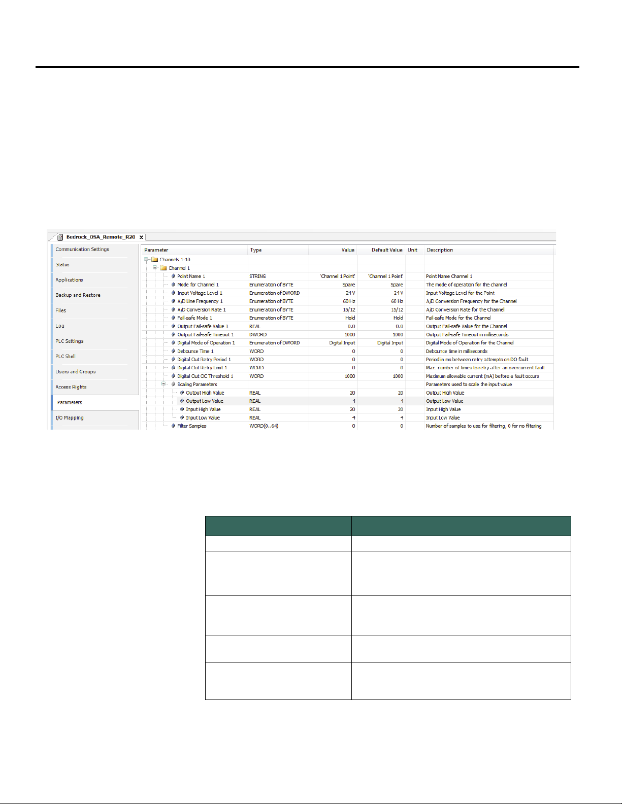
Parameters for an OSA Remote that are configurable in the Bedrock IDE are
shown in Figure 4-1 and summarized in Table 4-1.
Figure 4-1 OSA Remote Parameters in the Bedrock IDE
Table 4-1 OSA Remote Configurable Parameters
Parameter Name Description
Point Name User assigned name for the I/O point.
Operating mode for the channel. See
Mode for Channel
Input Voltage Level
A/D Line Frequency
A/D Conversion Rate
28 Bedrock Secure OSA Remote User Manual - BRDOC020_001 10/11/18
Modes”
of the OSA Remote operating modes.
Input voltage level for the module. The on and off
thresholds are shown in
For mode supporting discrete input.
50 Hz or 60 Hz.
For mode supporting analog input.
A/D Sampling rate. Each menu selection has a pair
of values for 60 Hz and 50 Hz, respectively.
For mode supporting analog input.
in “OSA Remote Operation” for a list
Table 4-2.
“Operating
Page 37

Software Configuration Chapter 4
Table 4-1 OSA Remote Configurable Parameters
Parameter Name Description
Used in event of communication failure between the
I/O subsystem and CPU.
Fail-safe – Module output is set to a default fail-safe
Fail-safe Mode
Output Fail-safe Value
Output Fail-safe Timeout
Digital Mode of Operation
Debounce Time
Digital Out Retry Period
Digital Out Retry Limit
Digital Out OC Threshold
Scaling Parameters
Filter Samples
value.
Hold – Module output is held at the current level
For modes supporting analog output or discrete
output.
Default fail-safe value if there is a communication
failure between the I/O subsystem and CPU and
Fail-safe mode is set to “Fail-safe”.
For modes supporting analog output or discrete
output.
Fail-safe timeout period in milliseconds. Configured
for each OSA Remote channel.
For modes supporting analog output or discrete
output.
Mode of operation for discrete inputs and NAMUR Digital Input, Counter, or Frequency.
For modes supporting discrete input or NAMUR.
Number of milliseconds (1-255) used for debounce
filtering.
Set to zero for no debounce filtering.
For modes supporting discrete input or NAMUR.
Number of milliseconds (3-255) between retries in
an overcurrent situation.
This parameter is ignored if Digital Out Retry Limit is
zero.
For mode supporting discrete output.
Number of retries (up to 255) in an overcurrent
situation. If set to zero, the channel stays latched off.
For mode supporting discrete output.
Maximum allowable current before a fault occurs.
Specified in milliamps.
For mode supporting discrete output.
Allows a configurable analog input range to be
scaled to a configurable output range, e.g., 0-100.
The input range is specified in milliamps for 4-20 mA
inputs or volts for 0-10 V inputs. Units are not
specified for the output range. Setting the output
range to be equal to the input range results in no
scaling. The default values for both input and output
are a low value of 4 and a high value of 20.
For modes supporting analog input.
Used to smooth a noisy signal. Specifies the number
of samples to average.
Enter zero for no averaging.
Enter 2-64 to specify number of samples.
For modes supporting analog input.
Additional detail pertaining to OSA Remote configuration parameters appears
in the following sections.
10/11/18 Bedrock Secure OSA Remote User Manual - BRDOC020_001 29
Page 38
Chapter 4 Software Configuration
Voltage Input Levels and Thresholds
Input Options and Sensor Typ es
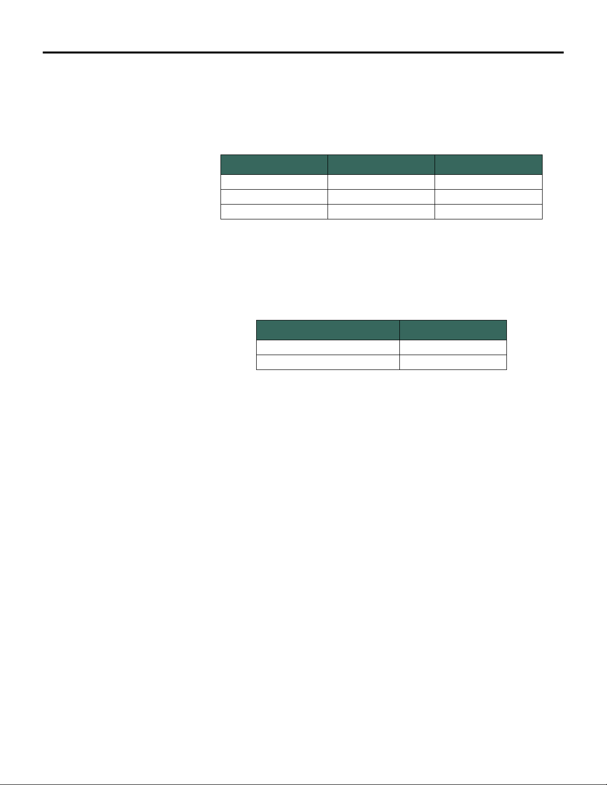
Table 4-2 shows the input voltage levels that are selectable in the Bedrock IDE
along with the corresponding thresholds for on and off voltage levels for each
setting.
Table 4-2 Input Voltage Settings and Thresholds
Input Voltage Setting Off Voltage On Voltage
5 V DC 2 V 4 V
12 V DC 6 V 8 V
24 V DC 12 V 14 V
Table 4-3 lists the type of input sensors and the input range of those sensors
available on the OSA Remote.
Table 4-3 Input Sensor Types and Ranges
Sensor Type Actual Input Range
4-20 mA 3.25-22 mA
0-10 V 0.1-12 V
Line Frequency Options Line frequency options are configurable to accommodate different locales. The
supported line frequency options for the OSA Remote are:
•50 Hz
•60 Hz
Analog to Digital Sampling Rates
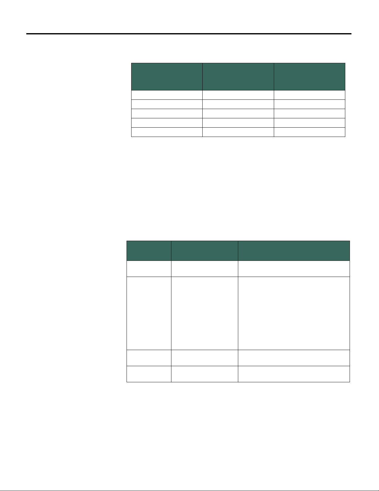
The analog to digital converter sampling rates and resolutions available for the
OSA Remote in the Bedrock IDE are shown in Table 4-4. The sampling rates
available are dependent on the line frequency and are measured in samples per
second (SPS).
30 Bedrock Secure OSA Remote User Manual - BRDOC020_001 10/11/18
Page 39
Software Configuration Chapter 4
Table 4-4 A/D Sampling Rates and Resolutions
Sampling Rate (SPS)
at 50 Hz Line
Frequency
81018
12 15 18
25 30 18
50 60 17
100 120 17
Sampling Rate (SPS)
at 60 Hz Line
Frequency
Resolution in Bits
I/O Update Rate The I/O update rate for the OSA Remote can be as fast as 3 milliseconds. It is
configured by setting the task interval in the Bedrock IDE.
Over Range Detection If the analog input or output circuitry detects out of range values, it sets the
corresponding flags and clamps the values. See Table 4-5. These values are visible
in the Bedrock IDE.
Table 4-5 Over Range Flags
Value
Typ e
Value Channel Status Value
Input clamped at 3.5 mA
Input clamped at 24.0 mA
Output clamped at 3.0 mA
Output clamped at 24.0 mA
0x0040
64 (decimal)
0x0010
16 (decimal)
If the input exceeds 24.9 mA, bit 2 will also
be set, indicating that the ADC has become
saturated. In this case, the status value will
be as follows:
0x0014
20 (decimal)
0x0044
68 (decimal)
0x0014
20 (decimal)
Fail-safe Output Feature The OSA Remote has a fail-safe output feature that protects the module in the
event of communication failure between the I/O subsystem and CPU. If no
communication is received from the CPU within the configured fail-safe
timeout period and the fail-safe mode configuration parameter is set to
“Fail-safe”, the output for each channel will be set to either a configured fail-safe
value or held at the current level.
10/11/18 Bedrock Secure OSA Remote User Manual - BRDOC020_001 31
Page 40
Chapter 4 Software Configuration
The fail-safe mode, default output fail-safe value, and fail-safe timeout period
are set using the Bedrock IDE. All fail-safe parameters are configured separately
for each channel on the OSA Remote.
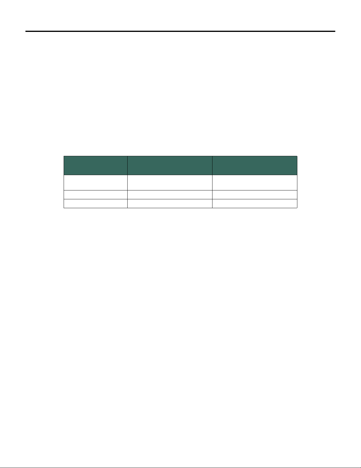
Digital Mode of Operation The OSA Remote can be configured for one of the digital modes of operation
listed in Table 4-6. These settings are applicable when the OSA Remote
operating mode is configured for one of the discrete input modes or for
NAMUR. The recommended digital mode of operation is affected by the input
frequency. The table shows the recommended modes for the listed input
frequencies.
Table 4-6 Recommended Modes of Operation
Input Frequency
< 100 Hz Digital Input
> 100 Hz Counter high-speed counter
> 100 Hz Frequency frequency measurement
Recommended Digital Mode
of Operation
Description
standard digital input with a
debounce filter
Note that regardless of the mode selected, the digital, counter, and frequency
values will all update in the Bedrock IDE. The most accurate value will be the
one corresponding to the selected mode.
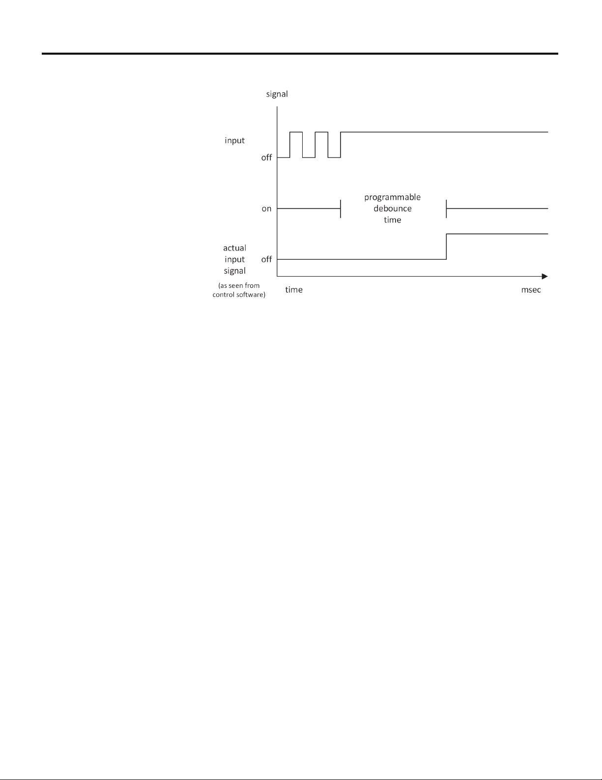
Debounce Filter The OSA Remote has a programmable debounce filter. The debounce filter can
be set to values of 0-255 milliseconds. If the filter is set to zero milliseconds, no
debounce filtering will occur. A non-zero value specifies the number of
milliseconds used for debounce filtering. A timing diagram for the debounce
filter is shown in Figure 4-2.
32 Bedrock Secure OSA Remote User Manual - BRDOC020_001 10/11/18
Page 41
Software Configuration Chapter 4
Figure 4-2 Debounce Filter Timing Diagram
Overcurrent Retry After an overcurrent situation occurs in discrete output mode, each channel can
either stay latched off or back-off and retry. Use the Bedrock IDE to specify the
overcurrent threshold (maximum current allowed before a fault occurs), number
of retries, and time period between retries. A channel will stay latched off if the
retry limit is set to zero.
Additional detail pertaining to OSA Remote configuration parameters appears
below.
Analog and Discrete I/O Mapped Variables
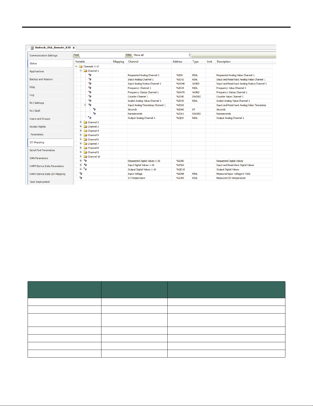
OSA Remote variables available for mapping to control programs are shown in
Figure 4-3 and described in Table 4-7.
10/11/18 Bedrock Secure OSA Remote User Manual - BRDOC020_001 33
Page 42
Chapter 4 Software Configuration
Figure 4-3 OSA Remote I/O Mapping
Mapped variables for individual channels shown in Figure 4-3 can be accessed
by expanding the folder for a channel or, in the case of digital values, expand the
node for each value to see the individual channel values. Note that for digital
values, only the “Value” field is used. Table 4-7 lists the mapped variable name,
variable type, and applicable operating mode for which the variable is used.
Table 4-7 OSA Remote Mapped Variables
Variable Type
Requested Analog REAL analog output
Input Analog REAL analog output, analog input, digital output, NAMUR
Input Analog Status WORD
Frequency REAL digital input, NAMUR
Frequency Status WORD digital input, NAMUR
Counter DWORD digital input, NAMUR
Scaled Analog Value REAL analog output, analog input
analog output, analog input, digital output
(see following table)
Applies to Operating Mode(s) with
the Listed Functionality
34 Bedrock Secure OSA Remote User Manual - BRDOC020_001 10/11/18
Page 43
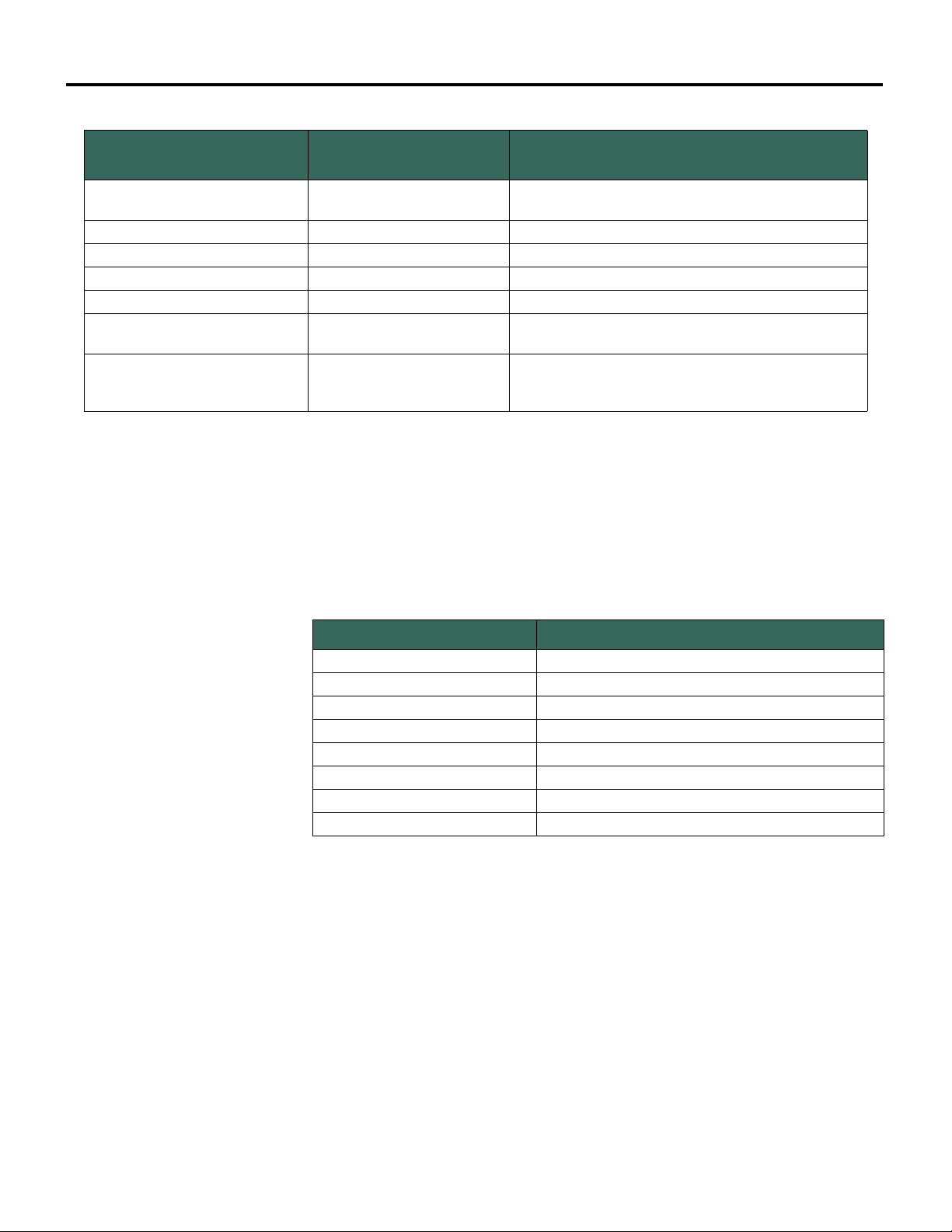
Table 4-7 OSA Remote Mapped Variables
Software Configuration Chapter 4
Variable Type
Input Analog Timestamp
Output Analog REAL analog output
Requested Digital Values WORD digital output
Input Digital Values WORD digital input, digital output, NAMUR
Output Digital Values WORD digital output
Input Voltage REAL
IO Temperature REAL
DT (seconds)
DWORD (nanoseconds)
analog output, analog input, digital output, NAMUR
Measured voltage input into the OSA Remote.
Not specific to an individual channel or operating mode
Measured temperature of the OSA Remote I/O
subsystem
Not specific to an individual channel or operating mode
Applies to Operating Mode(s) with
the Listed Functionality
The bit definitions for the Input Analog Status mapped variable indicate status
as shown in Table 4-8. This status information is applicable when an OSA
Remote channel is configured for analog input or analog output. When an OSA
Remote channel is configured for discrete output, bit 4 of the status word
indicates that the output is above the calibrated range.
Table 4-8 Input Analog Status Bit Definitions
Bit Number (Hex Value) Meaning
Bit 0 (0x0001) out of service
Bit 1 (0x0002) communication failure
Bit 2 (0x0004) A/D converter out of range
Bit 3 (0x0008) analog value is outside the calibrated range
Bit 4 (0x0010) input is above the calibrated range
Bit 5 (0x0020) not used
Bit 6 (0x0040) input is below the calibrated range
Bit 7 (0x0080) module is in fail-safe mode
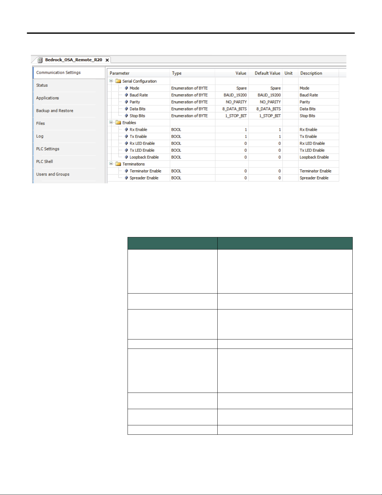
Serial Port Parameters Parameters that are configurable in the Bedrock IDE for the OSA Remote serial
port are shown in Figure 4-4 and summarized in Table 4-9.
10/11/18 Bedrock Secure OSA Remote User Manual - BRDOC020_001 35
Page 44
Chapter 4 Software Configuration
Figure 4-4 Serial Port Parameters
Table 4-9 Serial Port Parameters
Parameter Name Description
Specifies communication mode for the serial port
Spare - channel not used
Mode
Baud Rate
Parity
Data Bits Number of data bits per character - 5, 6, 7, or 8
Stop Bits
Rx Enable
Tx Enable
Rx LED Enable Set to TRUE to enable receive LED for the serial port
RS232
RS422
RS485_4WIRE
RS485_2WIRE
Minimum: 1200 bps
Maximum: 230,400 bps
Specifies parity for the serial port
NO_PARITY
EVEN - even number of one bits
ODD - odd number of one bits
Number of stop bits per character:
1_STOP_BIT - one stop bit will be used
1.5_TO_2_STOP_BITS - 1.5 stop bits when using
5 data bits, otherwise 2 stop bits
Set to TRUE to enable receive function for the serial
port
Set to TRUE to enable transmit function for the serial
port
36 Bedrock Secure OSA Remote User Manual - BRDOC020_001 10/11/18
Page 45
Software Configuration Chapter 4
Table 4-9 Serial Port Parameters
Parameter Name Description
Serial Port Mapped Variables
Tx LED Enable
Loopback Enable
Terminator Enable
Spreader Enable Used to reduce noise on RS-422 and RS-485 lines
Set to TRUE to enable transmit LED for the serial
port
Set to TRUE to use the Rx line to verify that data
was transmitted correctly. Disables the external
receiver.
Enables 120 ohm terminator resistor (RS-422 and
RS-485 only). Used for long communication lines.
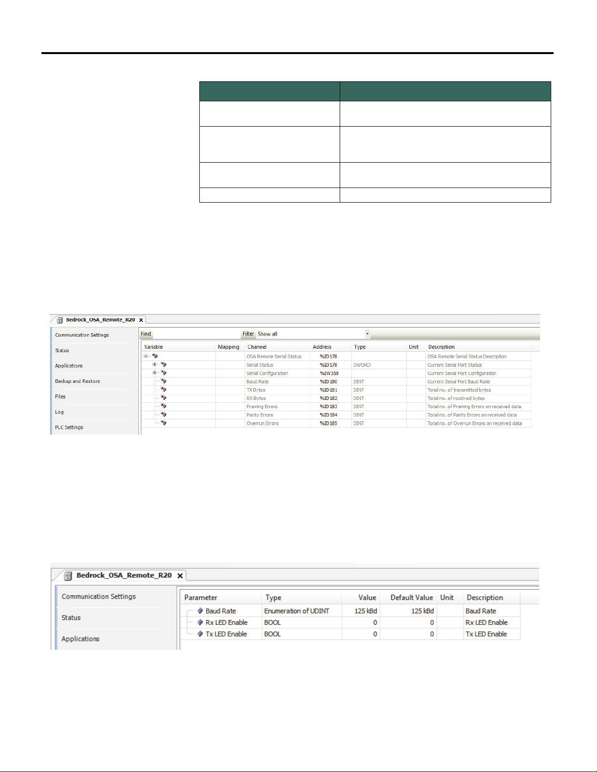
Variables in the Bedrock IDE that can be mapped to control programs and are
specific to operation of the serial port are shown in Figure 4-5. These variables
provide port status and diagnostic information.
Figure 4-5 Serial Port Mapped Variables
CAN Bus I/O Parameters
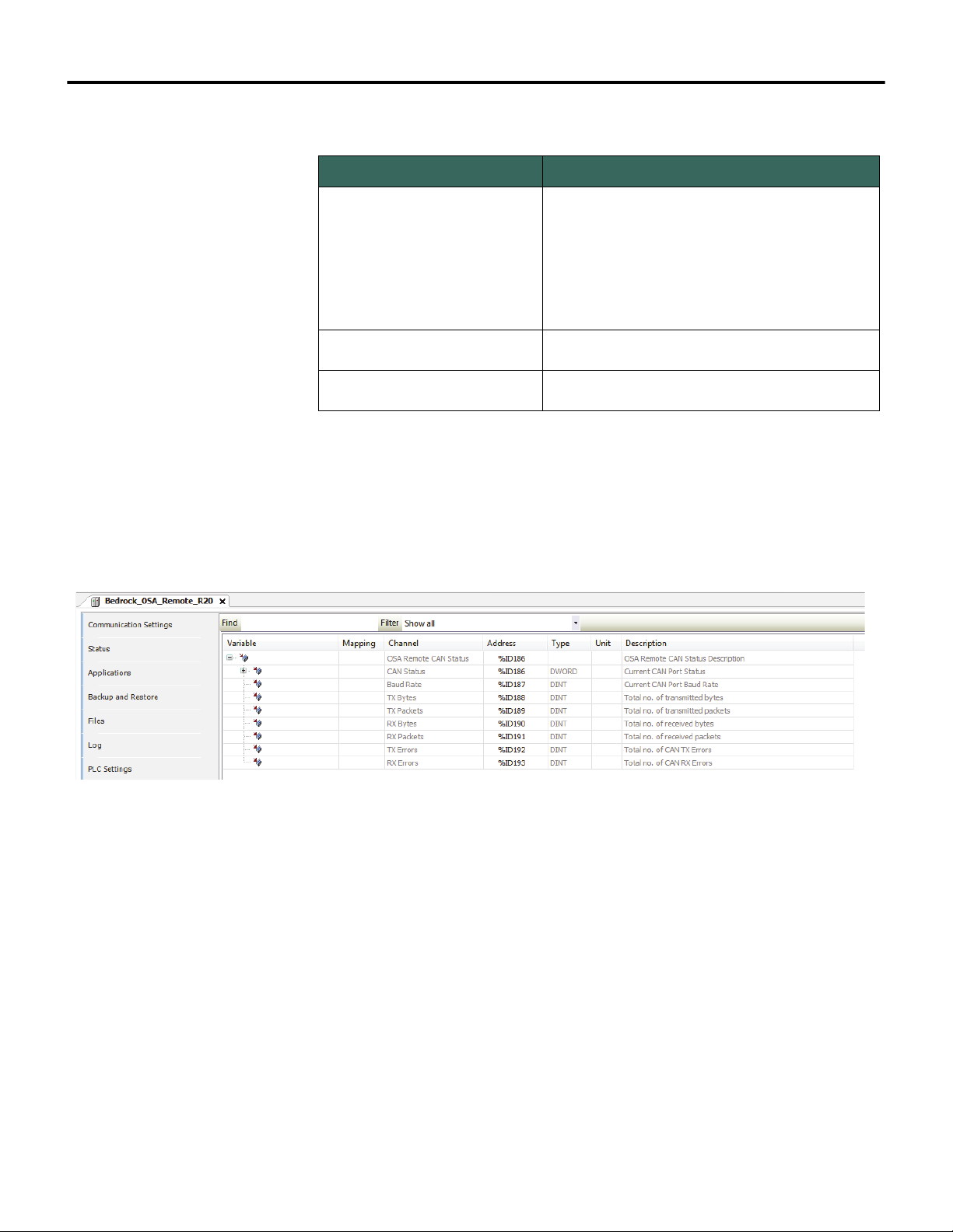
Parameters that are configurable in the Bedrock IDE for the OSA Remote CAN
bus port are shown in Figure 4-6 and summarized in Table 4-10.
Figure 4-6 CAN Bus Parameters
10/11/18 Bedrock Secure OSA Remote User Manual - BRDOC020_001 37
Page 46
Chapter 4 Software Configuration
Table 4-10 CAN Bus Parameters
Parameter Name Description
The baud rate for the CAN bus I/O port can be set to
one of the following values:
CAN Bus Mapped Variables
Baud Rate
Rx LED Enable
Tx LED Enable
100 kbps
125 kbps
200 kbps
250 kbps
500 kbps
Set to TRUE to enable receive LED for the CAN bus
port
Set to TRUE to enable transmit LED for the CAN bus
port
Variables in the Bedrock IDE that can be mapped to control programs and are
specific to operation of the CAN Bus I/O port are shown in Figure 4-7. These
variables provide port status and diagnostic information.
Figure 4-7 CAN Bus Mapped Variables
HART Devices For information on using the Bedrock Field Device Tool to configure an OSA
Remote for communication with field devices that support the HART
Communication Protocol, see “HART Device Configuration”.
For a list of HART variables available in the Bedrock IDE, see Appendix D,
“HART Variables”.
38 Bedrock Secure OSA Remote User Manual - BRDOC020_001 10/11/18
Page 47

Chapter 5
HART Device Configuration
Overview The Bedrock Field Device Tool (FDT) provides the capability to configure a
Bedrock Secure OSA Remote to interface to smart field devices that support the
HART Communication Protocol. This chapter provides information on the
following topics and tasks related to configuration of HART field devices:
• overview of the Bedrock FDT, Bedrock DTMs and third-party
DTMs
• enabling OSA Remotes for HART communication in the Bedrock
IDE
• configuration of Bedrock hardware in the Bedrock FDT
• configuration of third-party hardware in the Bedrock FDT
Intended Audience The information in this section is intended for use by engineers, programmers,
and technicians who need to configure HART devices for use with Bedrock
Secure OSA Remotes.
HART Communication Protocol
Bedrock Field Device Tool
Prerequisite for Custom Certificates
The HART Communication Protocol supports bi-directional communication
and provides a digital communication link between host systems and smart field
devices.
HART passthrough is supported using the Bedrock FDT. For a list of available
HART variables, see Appendix D, “HART Variables”. The Bedrock IDE
provides the ability to map HART variables to your control program.
For more information on the HART Communication Protocol, see the HART
Communication Foundation website (http://www.hartcomm.org).
The Bedrock Field Device Tool is a frame application based on FDT technology.
The tool provides users with the capability to configure devices that support the
HART Communication Protocol so that the devices can be used with Bedrock
Secure OSA Remotes. The Bedrock FDT allows the user to scan their
environment for network cards, OSA Remotes, and field devices. Additional
information on the Bedrock FDT can be found within the Bedrock FDT help
content.
If using custom certificates, ensure that the certificates are available before using
the Bedrock IDE. The Bedrock IDE and Bedrock FDT use the same certificates.
See “Customer-specific OPC UA Security Keys” for more information.
10/11/18 Bedrock Secure OSA Remote User Manual - BRDOC020_001 39
Page 48

Chapter 5 HART Device Configuration
DTMs Device type managers (DTMs) are software components that provide an
interface for configuring OSA Remotes and third-party devices that support
HART. DTMs are implemented within the frame application and can be
categorized as follows:
• Communication and gateway DTMs provided by Bedrock
Automation provide an interface to Bedrock devices on the user’s
network. Bedrock provides DTMs for network interfaces and OSA
Remotes (Controllers).
• Device DTMs provide an interface to and allow configuration of
third-party devices that support HART. Third-party DTMs are
supplied by the device manufacturer and not Bedrock Automation.
Software Components The following software components must be installed to configure HART
devices for use with Bedrock Secure OSA Remotes.
Configuring OSA Remotes with HART Devices
• The Bedrock Field Device Tool is installed during installation of the
Bedrock IDE. A shortcut to the FDT is created on the workstation’s
desktop.
• Bedrock DTMs are also installed during installation of the Bedrock
IDE. Bedrock DTMs will be available when configuring HART
devices (described below).
• DTMs for third-party field devices are installed separately. Contact
the device manufacturer to obtain any files needed for installation.
This section provides an example of how to use the Bedrock FDT to setup a basic
configuration to enable an OSA Remote to communicate with a HART device.
Several of the user actions described in the example procedure are available both
in the application Ribbon as well as by right-clicking an item and selecting from
a context menu. The example procedure will show user selections from the
Ribbon.
Steps for adding gateway or device DTMs will provide instructions for both
scanning a network as well as manually adding a DTM to the network
topology. Manually adding DTMs is useful for working offline, e.g., in cases
where a network is unavailable.
40 Bedrock Secure OSA Remote User Manual - BRDOC020_001 10/11/18
Page 49
HART Device Configuration Chapter 5
Note
During HART device configuration, attempts by the Bedrock FDT or Bedrock IDE
to connect to an OSA Remote may require a user response to security prompts
as follows.
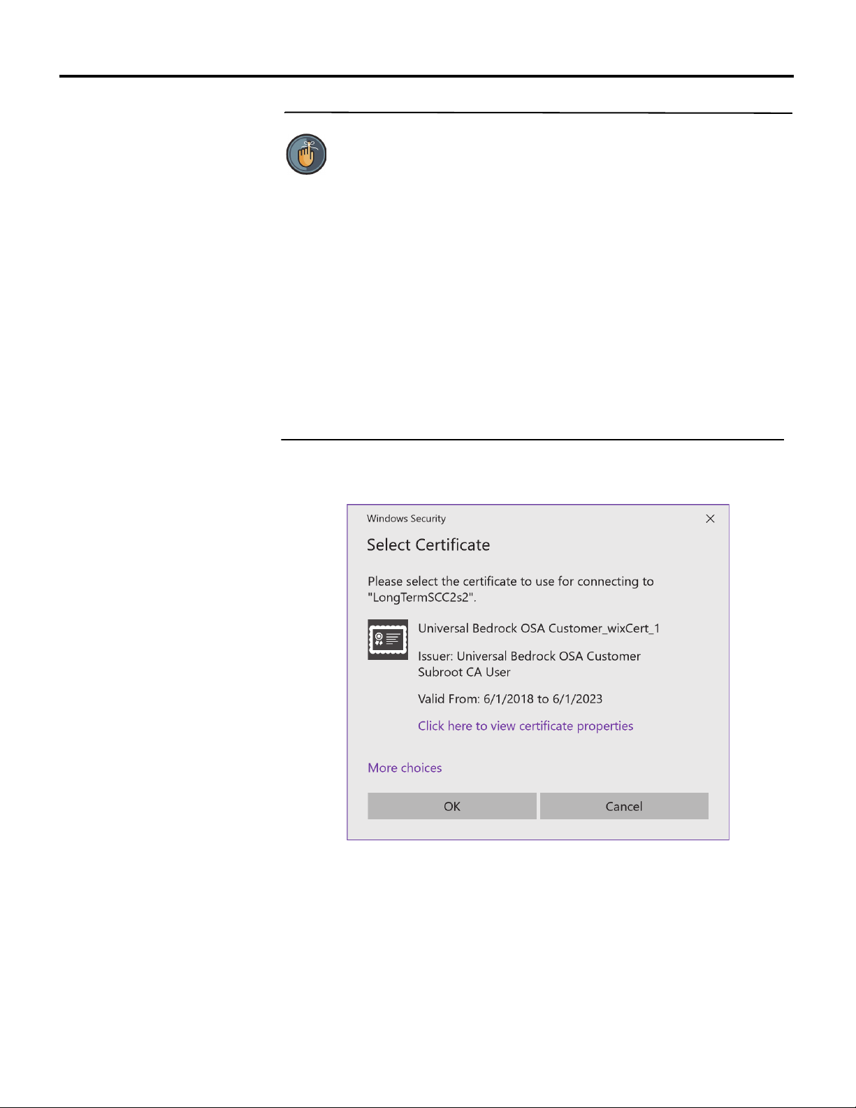
When attempting to connect to an OSA Remote, a Windows Security prompt
may be displayed. Select the displayed certificate or choose another certificate
to use for connecting to the remote.
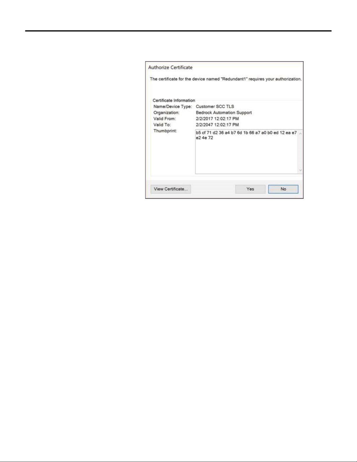
When attempting an initial connection to an OSA Remote, the OSA Remote will
respond with a certificate. An Authorize Certificate prompt will be displayed in
the Bedrock FDT. Authorization of the certificate is required to continue
configuration.
The Windows Security prompt and Authorize Certificate prompt are shown in
the following figures.
Figure 5-1 Select Certificate Prompt
10/11/18 Bedrock Secure OSA Remote User Manual - BRDOC020_001 41
Page 50
Chapter 5 HART Device Configuration
Figure 5-2 Authorize Certificate Prompt
The following procedure provides an example of how to use the Bedrock FDT
for HART device configuration.
1. Ensure that the Bedrock IDE has been installed. Installation of the
Bedrock IDE includes the Bedrock FDT and Bedrock DTMs. Ensure
that the software is up to date.
2. Ensure that any DTMs from third-party device manufacturers have been
installed.
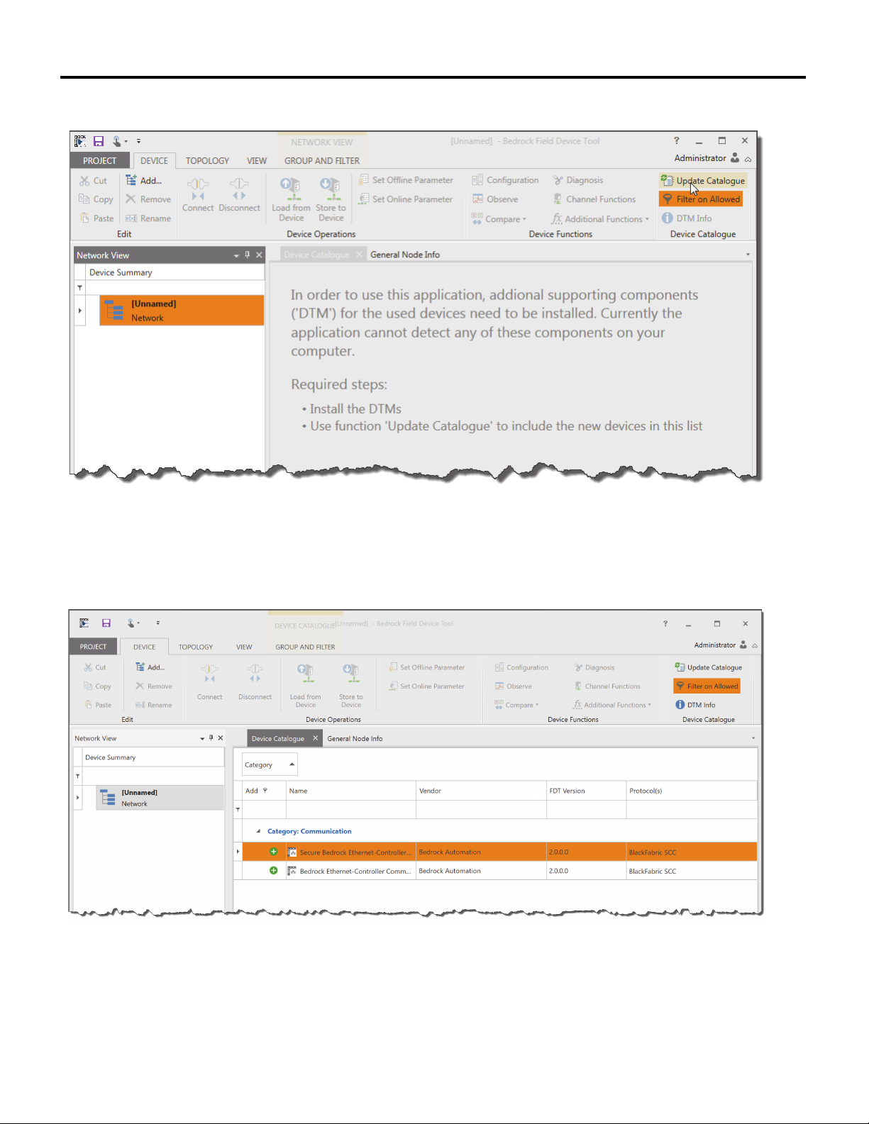
3. Create a blank project from the start page of the Bedrock FDT. A
network node will be highlighted in the Network View (see Figure 5-3).
If the DTMs were installed for the first time or if existing DTMs were
updated, the device catalogue will need to be updated as shown in the
figure.
42 Bedrock Secure OSA Remote User Manual - BRDOC020_001 10/11/18
Page 51
HART Device Configuration Chapter 5
Figure 5-3 New FDT Project
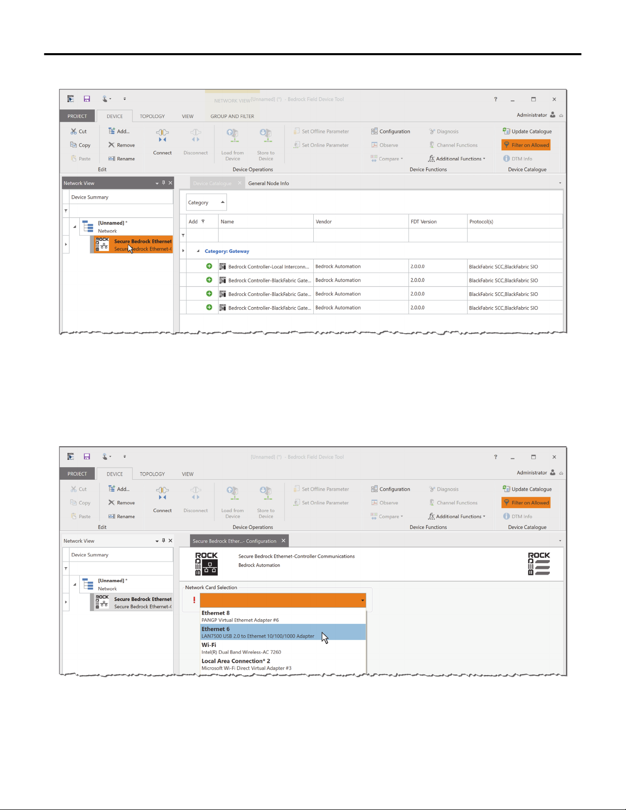
4. Select a Bedrock communication DTM from the Device Catalogue as
shown in Figure 5-4. A “secure” version of a DTM should be selected.
Figure 5-4 Select Communication DTM
5. Double-click the communication DTM that was just added to the
Network View as shown in Figure 5-5.
10/11/18 Bedrock Secure OSA Remote User Manual - BRDOC020_001 43
Page 52
Chapter 5 HART Device Configuration
Figure 5-5 Select Network Adapter
6. In the Network Card Selection pane, select the network card for the
OSA Remote that you are trying to connect to from the drop-down
menu as shown in Figure 5-6.
Figure 5-6 Select Network Device
44 Bedrock Secure OSA Remote User Manual - BRDOC020_001 10/11/18
Page 53
HART Device Configuration Chapter 5
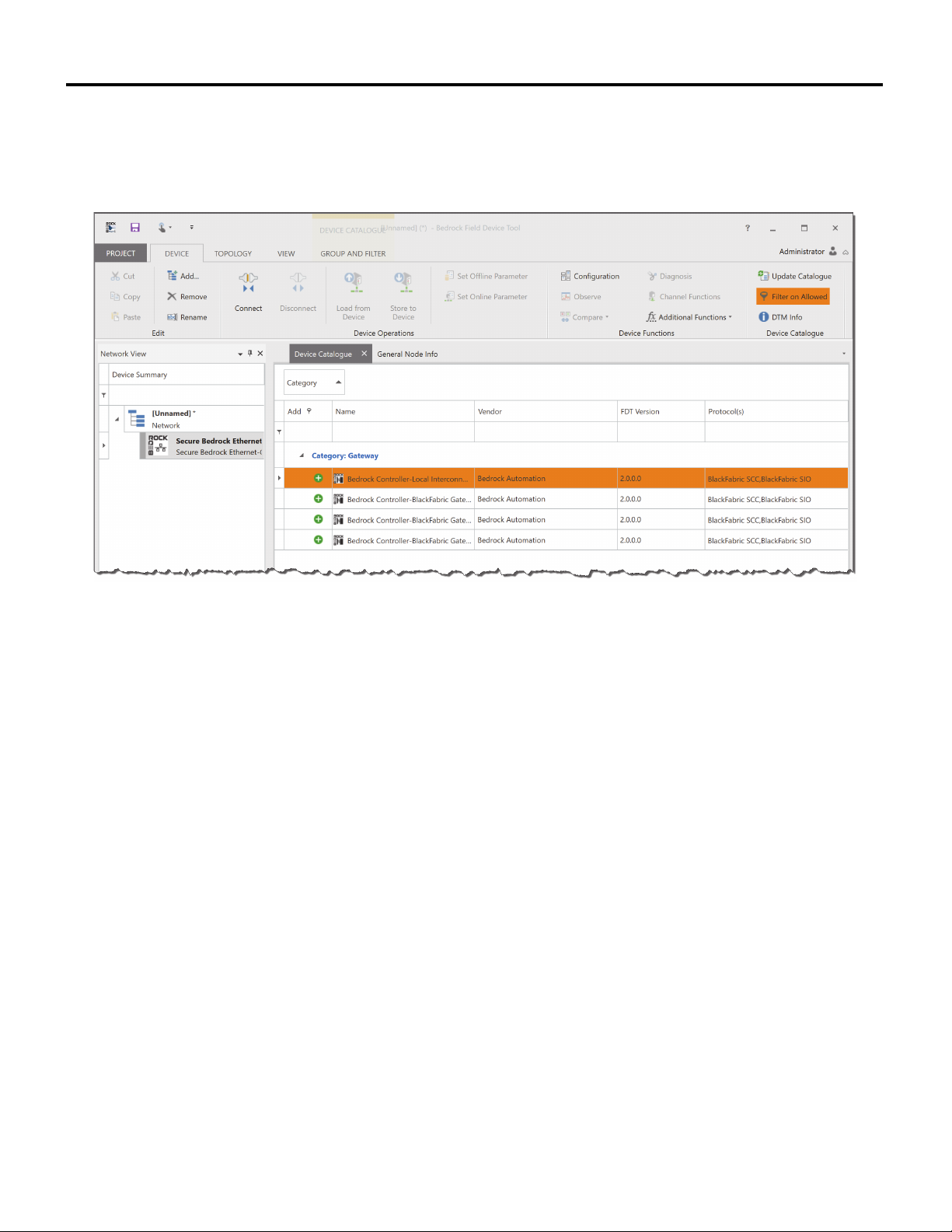
7. Click OK. A list of available DTMs will be displayed as shown in
Figure 5-7. These will be Controller-Local Interconnect DTMs or
Controller-Gateway DTMs.
Figure 5-7 Controller Gateway DTMs
8. For an OSA Remote, add a Controller-Local Interconnect DTM. The
DTM can be added either automatically or manually. Select the
communication DTM in Network View and then choose one of the
following:
• To automatically add a Controller-Local Interconnect DTM,
click Scan and Select on the Topology tab in the Ribbon. The
Bedrock FDT will query the network for available OSA
Remotes. Go to step 9.
• Or to manually add a DTM to your network topology without
querying the network, click the plus sign next to the DTM
name (see Figure 5-7) in the Device Catalogue. Go to step 10.
10/11/18 Bedrock Secure OSA Remote User Manual - BRDOC020_001 45
Page 54
Chapter 5 HART Device Configuration
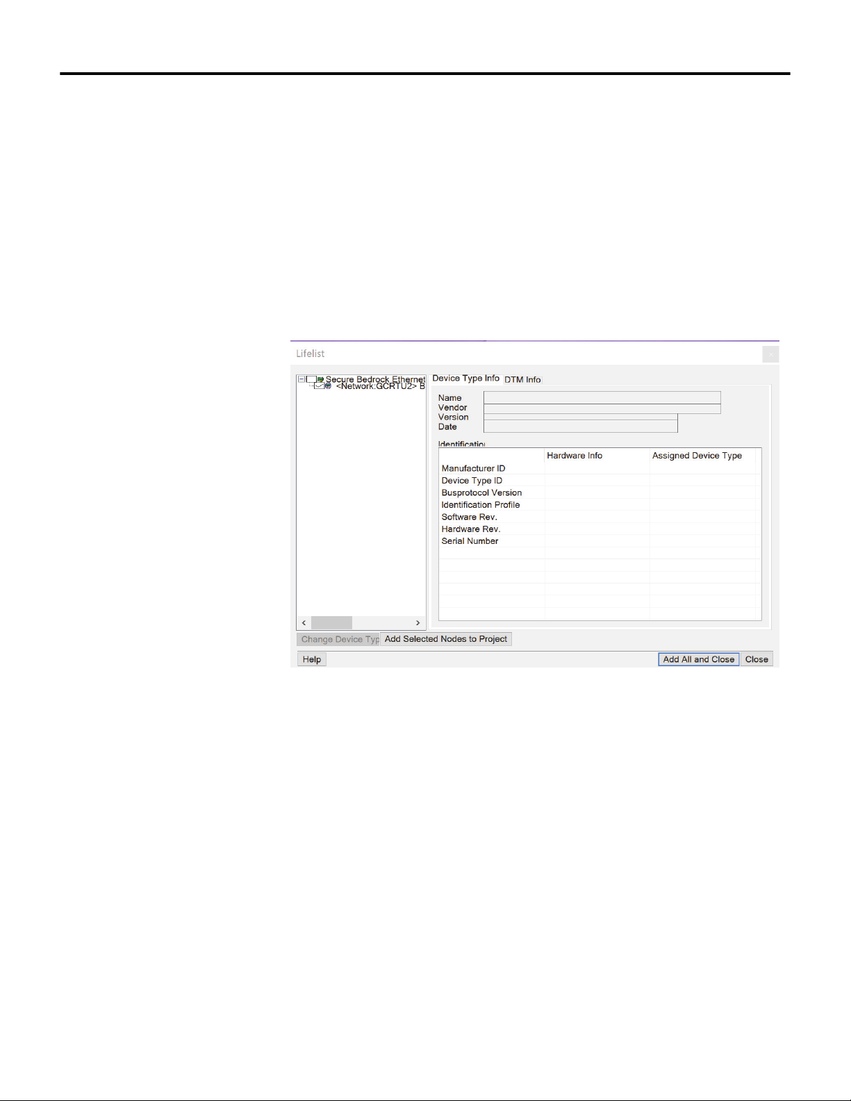
9. If you elected to automatically add a DTM in the previous step, a list of
the DTMs that were found will be displayed after any certificates have
been selected (see Figure 5-8). Use the checkboxes to select the DTM(s)
you would like to add to your project and then do one of the following:
• Click Add All and Close. This will add all compatible DTMs in
the list to your project.
• Or click Add Selected Nodes to Project. This will add only
those DTMs with check marks to your project. Click Close to
dismiss the dialog.
Figure 5-8 Adding Gateway DTMs After Scan
10. The Network View pane will be updated with the selected DTM(s) as
shown in Figure 5-9. Select a Bedrock Controller-Local Interconnect
Gateway DTM in the Network View to display a list of gateway DTMs
for SIO-Hart.
46 Bedrock Secure OSA Remote User Manual - BRDOC020_001 10/11/18
Page 55
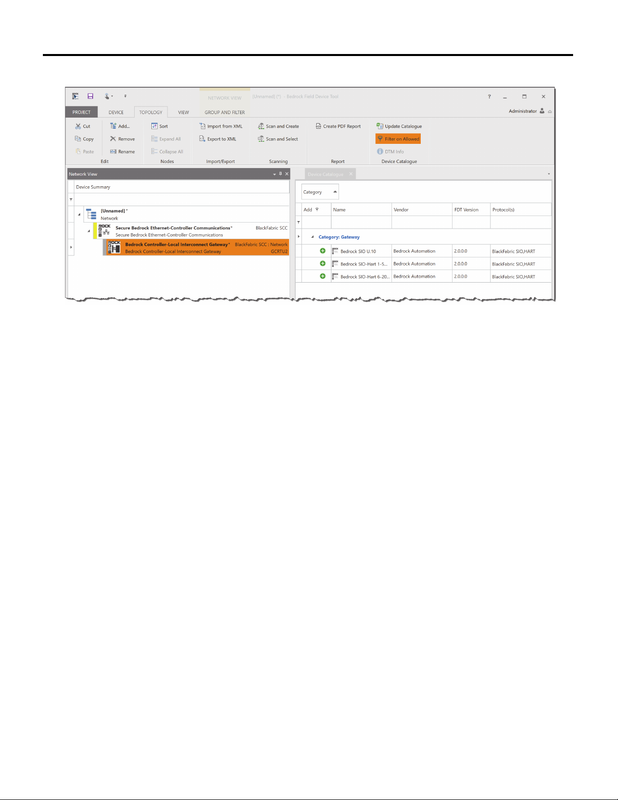
HART Device Configuration Chapter 5
Figure 5-9 Select and Scan Controller-Local Interconnect Gateway DTM in Network View
11. Add a gateway DTM for SIO-Hart. The gateway DTM can be added
either automatically or manually. Choose one of the following.
• To automatically add a gateway DTM for SIO-Hart, click Scan
and Select on the Ribbon as shown in Figure 5-9. The Bedrock
FDT will query the network for available Bedrock Secure OSA
Remotes. Go to step 12.
• Or to manually add a gateway DTM for SIO-Hart to your
network topology without querying the network, click the plus
sign next to the DTM in the Device Catalogue that is named
“Bedrock SIO-Hart 6.20 ANALOG”. Go to step 13.
12. If you elected to automatically add a DTM (Scan and Select) in the
previous step, a list of the DTMs that were found will be displayed as
shown in Figure 5-10. Select the checkbox for the “Bedrock SIO-Hart
6.20 ANALOG” DTM and then do one of the following:
• Click Add All and Close. This will add the selected DTM to
your project.
• Or click Add Selected Nodes to Project. This will add the
selected DTM to your project. Click Close to dismiss the
dialog.
10/11/18 Bedrock Secure OSA Remote User Manual - BRDOC020_001 47
Page 56
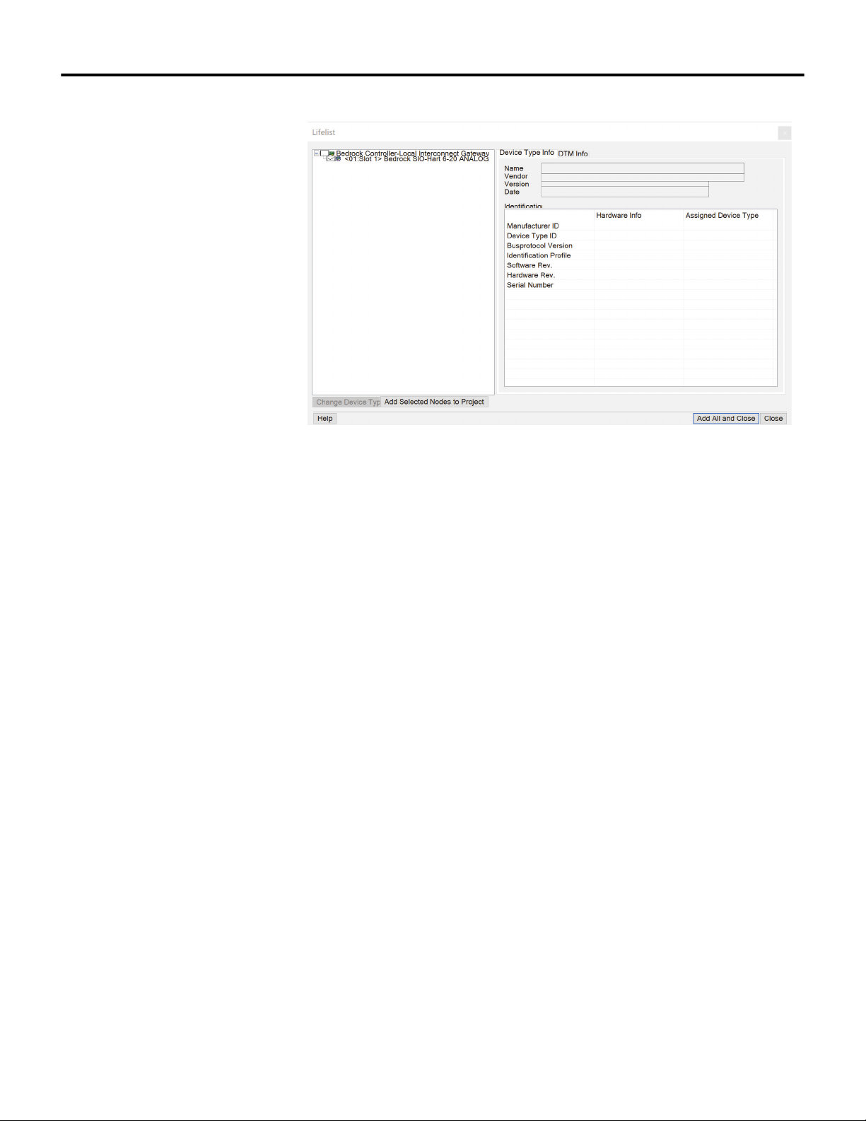
Chapter 5 HART Device Configuration
Figure 5-10 Adding DTM After Scan
13. Once gateway DTMs for SIO Hart have been added to your project, the
Network View pane will be updated as shown in Figure 5-11. Select the
“Bedrock SIO-Hart 6.20 ANALOG” DTM to see a list of device DTMs
for HART devices in the Device Catalogue.
48 Bedrock Secure OSA Remote User Manual - BRDOC020_001 10/11/18
Page 57
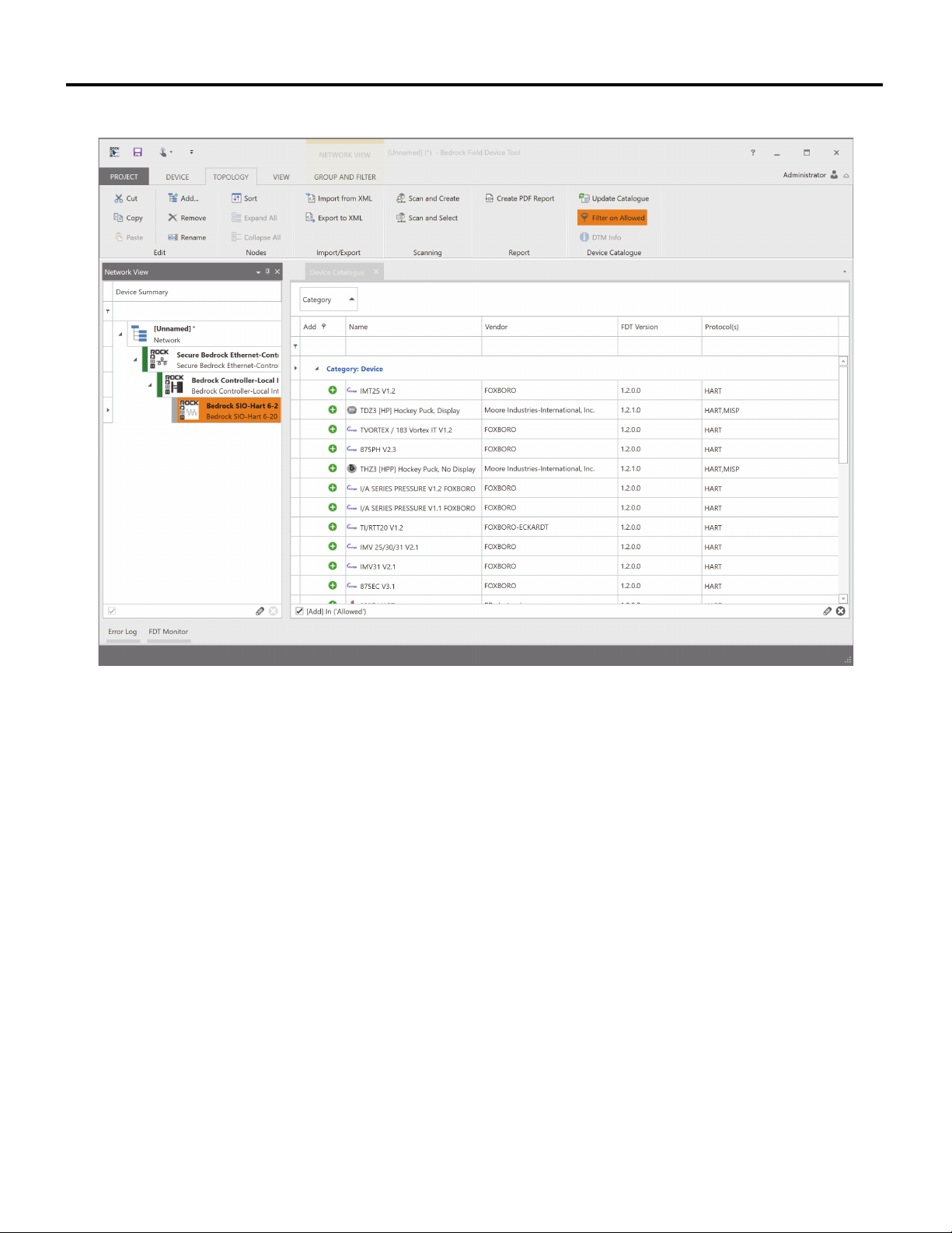
HART Device Configuration Chapter 5
Figure 5-11 Device DTM in Device Catalogue
14. Add a device DTM for a HART device. The device DTM can be added
either automatically or manually. Choose one of the following.
• To automatically add a device DTM for a HART device, click
Scan and Select on the Ribbon as shown in Figure 5-11.
• Or to manually add a device DTM to your network topology
without querying the network, click the plus sign next to the
DTM name in the Device Catalogue.
15. You will be prompted for a list of channels to scan as shown in
Figure 5-12. These correspond to channels on the OSA Remote. Select
the channels you would like to scan and then click OK.
10/11/18 Bedrock Secure OSA Remote User Manual - BRDOC020_001 49
Page 58
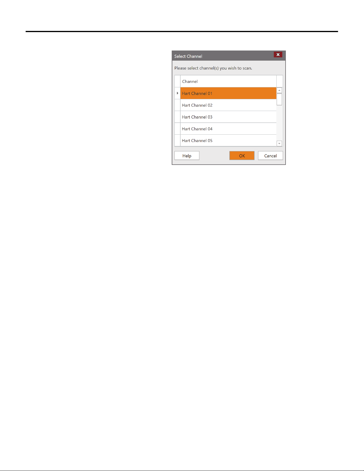
Chapter 5 HART Device Configuration
16. Perform this step only if you elected to automatically add a device
Figure 5-12 Scan Channels for HART Devices
DTM. A list of the DTMs that were found will be displayed as shown in
Figure 5-13. Use the checkbox to select the DTM(s) you would like to
add to your project and then do ones of the following:
• Click Add All and Close. This will add all compatible DTMs in
the list to your project.
• Or click Add Selected Nodes to Project. This will add only
those DTMs with check marks to your project. Click Close to
dismiss the dialog.
50 Bedrock Secure OSA Remote User Manual - BRDOC020_001 10/11/18
Page 59
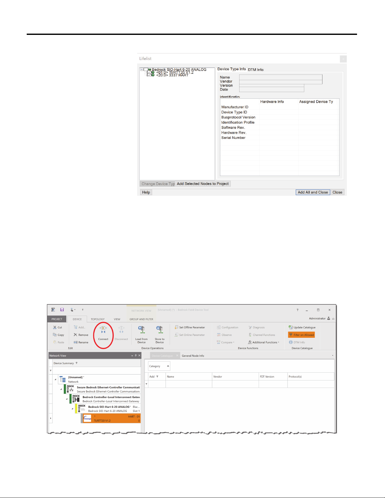
HART Device Configuration Chapter 5
Figure 5-13 Adding a Device DTM
17. The Network View pane will be updated with device DTMs as shown in
Figure 5-14. Do one of the following:
• If you elected to automatically add a DTM in step 14, then
select a device DTM and click the Connect button on the
Device tab on the Ribbon to connect to a HART device.
• Or if you elected to manually add a DTM in step 14, then go to
step 19.
Figure 5-14 Device DTM Added to Network View
10/11/18 Bedrock Secure OSA Remote User Manual - BRDOC020_001 51
Page 60
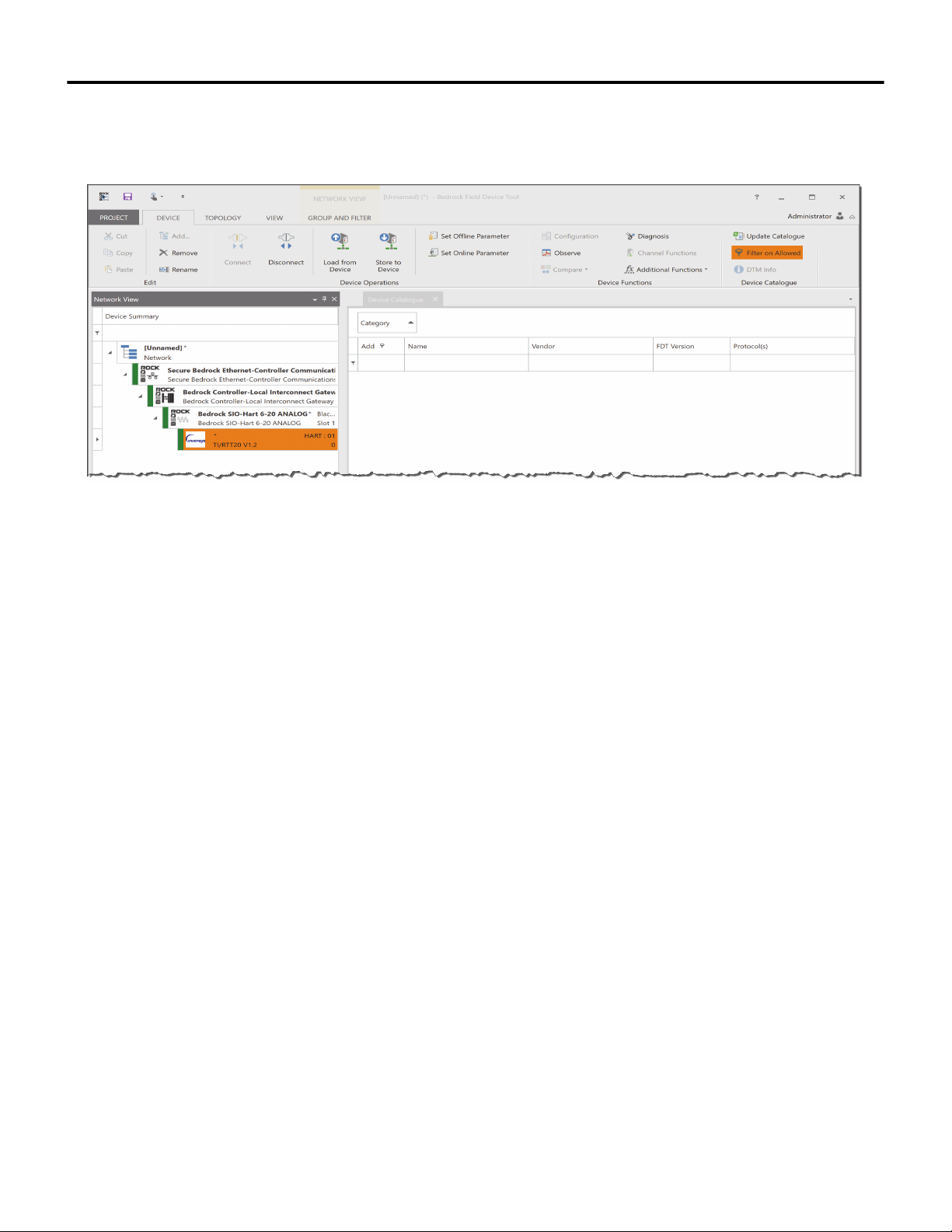
Chapter 5 HART Device Configuration
18. The nodes in the Network View Device Summary should all be in the
Connected state as indicated by the green status bars. See Figure 5-15.
Figure 5-15 All Nodes Connected
19. Refer to the device manufacturer’s instructions for using the DTM to
configure and maintain the device.
Common Functions This section summarizes common functions that are available in the Bedrock
FDT user interface. In addition to being located on the FDT Ribbon, these
functions can also be accessed from context menus (right-clicking).
Topology Tab The following functionality is available on the Topology Tab located on the
Bedrock FDT Ribbon.
Import from XML
Reads previously saved topology information from an XML file.
Export to XML
Saves topology information for the selected mode to an XML file. Selected
devices must be offline.
Scan and Create
Use this to create a network and build a complete topology tree from scanned
DTMs.
52 Bedrock Secure OSA Remote User Manual - BRDOC020_001 10/11/18
Page 61

HART Device Configuration Chapter 5
Scan and Select
Use this to scan the selected DTM in an existing network to find child DTMs.
Update Catalogue
Updates the device catalogue with any DTMs that were installed since the last
update. This function can also be accessed from the Device Tab.
Device Tab The following functionality is available on the Device Tab located on the
Bedrock FDT Ribbon.
Connect
Send request to connect to selected device. This option is available for all DTMs.
Disconnect
Send request to disconnect from selected device. This option is available for all
DTMs.
Load from Device
This option is available for HART Devices. Parameters from the device are
loaded into the FDT memory. If the device state is Disconnected, the FDT will
attempt to connect to the device.
Store to Device
This option is available for HART Devices. Parameters in the FDT memory are
stored to the selected device. If the device state is Disconnected, the FDT will
attempt to connect to the device.
Set Offline Parameter
This option is available for HART Devices and if selected will display the set of
parameters that is saved with the project or default values if the project has not
been saved. Behavior is specific to the selected device DTM. An example of a
display of offline parameters is shown in Figure 5-16.
10/11/18 Bedrock Secure OSA Remote User Manual - BRDOC020_001 53
Page 62
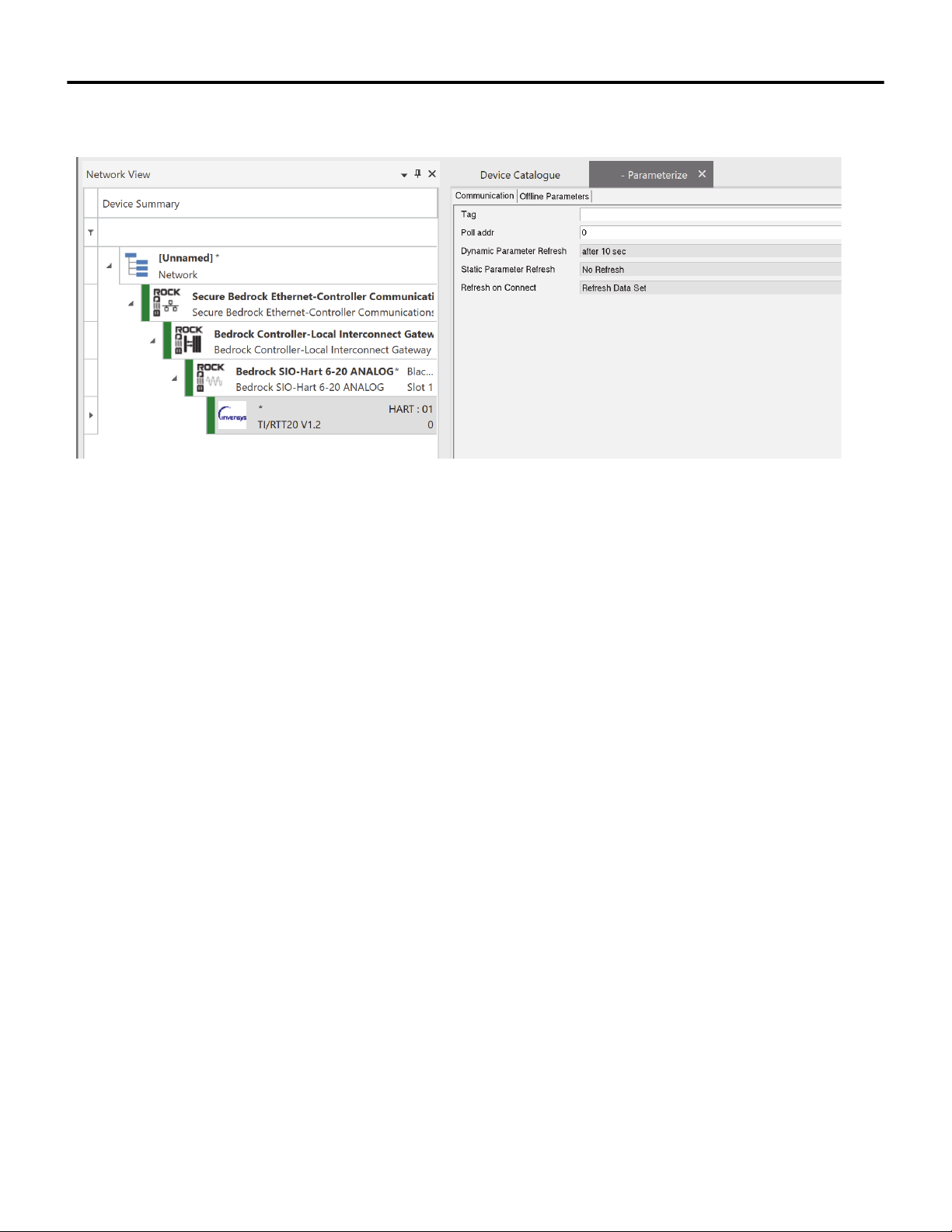
Chapter 5 HART Device Configuration
Figure 5-16 Offline Parameters for a HART Device
Set Online Parameter
This option is available for HART Devices and if selected will display the set of
parameters that is saved with the HART device. The device must be in the
Connected state for this option to be selected. Behavior is specific to the selected
device DTM.
Configuration
Allows configuration of a device such as selection of a network card for a
Communication DTM.
Observe
Allows observation of device operation. Behavior is specific to the selected device
DTM.
Diagnosis
Displays diagnostic information for the selected device. Behavior is specific to
the selected device DTM. A sample display of diagnostic information is shown
in Figure 5-17.
54 Bedrock Secure OSA Remote User Manual - BRDOC020_001 10/11/18
Page 63
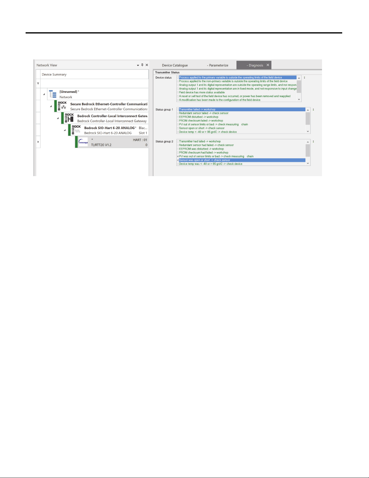
HART Device Configuration Chapter 5
Figure 5-17 Diagnostic Information for a HART Device
10/11/18 Bedrock Secure OSA Remote User Manual - BRDOC020_001 55
Page 64
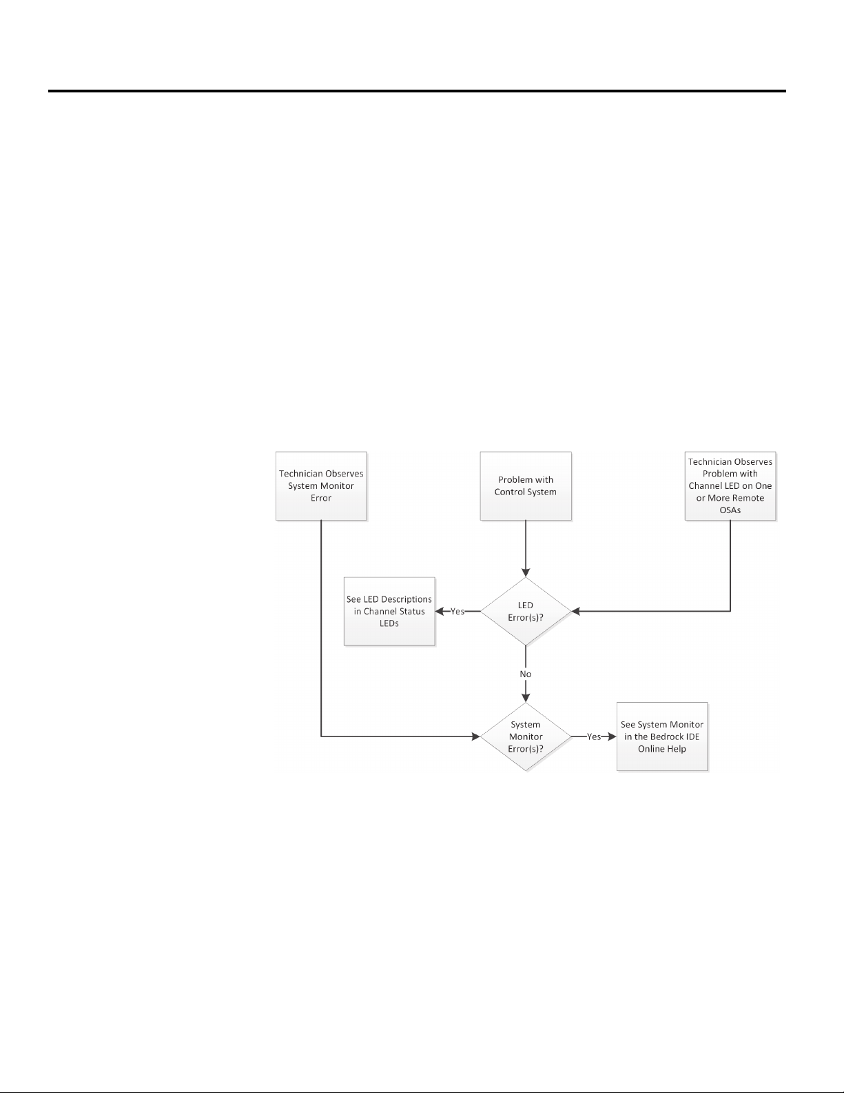
Chapter 6
Monitoring and Troubleshooting
Overview The Bedrock IDE System Monitor tool provides a graphical display that allows
users to view and monitor the status of system components. The System Monitor
tool is described in the Bedrock IDE online help.
In addition to the System Monitor tool, Bedrock Secure OSA Remotes provide
LEDs on the front of the unit, a system logging feature, and status information
in the Bedrock IDE to assist in troubleshooting. These troubleshooting methods
are discussed in the following sections. It may also be necessary to look at code in
the Bedrock IDE in order to troubleshoot control application issues.
Tro ubl esho oting Flowchart
Follow the flowchart in Figure 6-1 should a user observe a problem with an OSA
Remote.
Figure 6-1 Troubleshooting Flowchart
General Troubleshooting Tasks
56 Bedrock Secure OSA Remote User Manual - BRDOC020_001 10/11/18
Use the LED blink codes to help determine which component may be
compromised.
In addition to the channel status, LED blink codes, use the following list of
troubleshooting techniques to help resolve system errors.
• Verify that the OSA Remote has been correctly configured.
Page 65
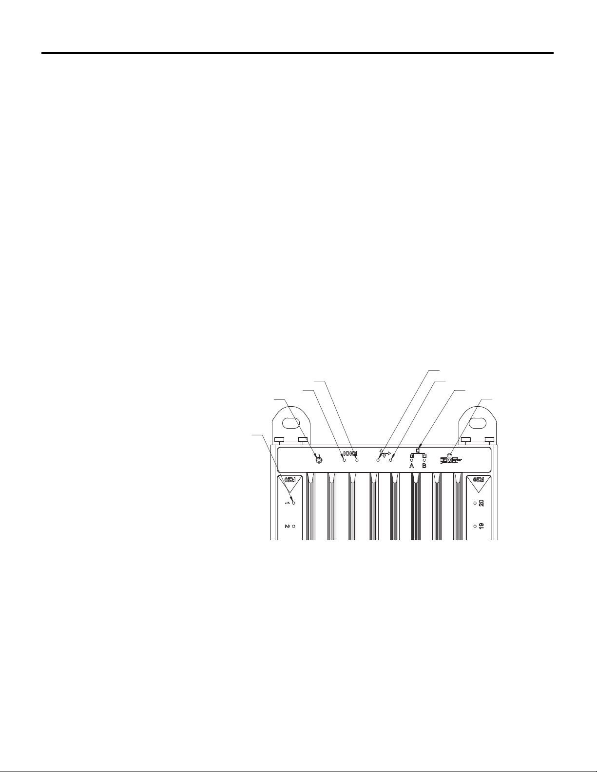
Monitoring and Troubleshooting Chapter 6
STATUS LED
CYBER LED
ETHERNET LEDS
CHANNEL LED
SERIAL TX LED
SERIAL RX LED
CAN BUS RX LED
CAN BUS TX LED
• Verify that all physical wires are connected.
• Verify that all physical wires are working.
• Use the Bedrock IDE to check that values are as expected.
Built-in Self Test On power-up, the OSA Remote firmware will execute a built-in self test of sys-
tem components as follows:
• A test of the OSA Remote RAM will be run on startup.
• A read/write test of the flash memory will be performed.
• The input voltage will be checked on each channel.
• The OSA Remote LEDs will be turned on and off. This allows the
user to visually verify that the OSA Remote LEDs are functioning.
OSA Remote LEDs LEDs located on the front of Bedrock Secure OSA Remotes provide information
about the operational status of the unit. The LEDs are shown in Figure 6-2.
10/11/18 Bedrock Secure OSA Remote User Manual - BRDOC020_001 57
Figure 6-2 OSA Remote LEDs
The LEDs indicate the status of OSA Remote operation as follows:
• The Status LED provides an indication of OSA Remote system
status including information pertaining to the boot process as well as
authentication.
• Serial LEDs indicate that serial data is being transmitted (left LED)
or received (right LED).
Page 66
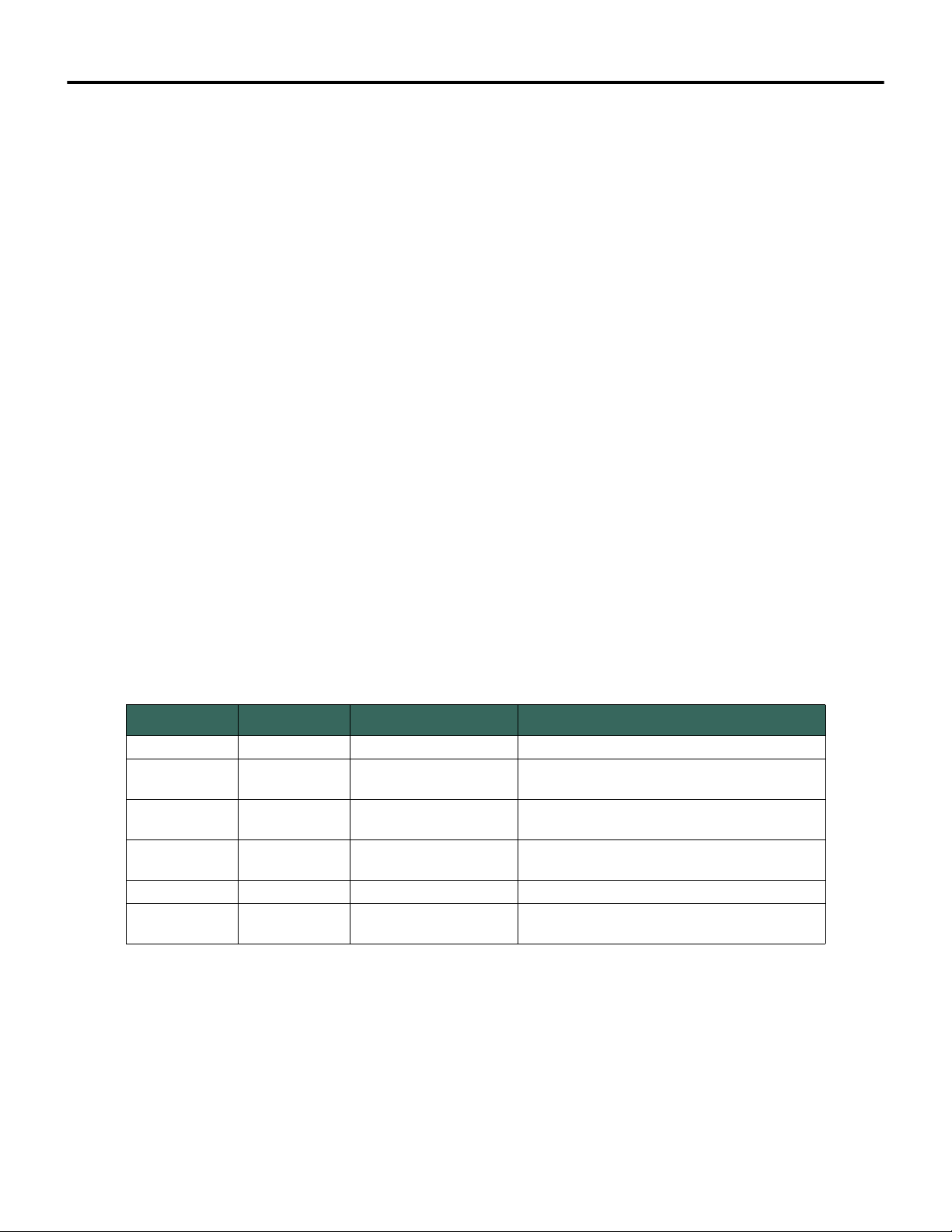
Chapter 6 Monitoring and Troubleshooting
• CAN bus LEDs indicate that data is being transmitted (left LED) or
• Ethernet LEDs indicate the status of the Ethernet links for Port A
• The Cyber LED can be used to observe the loading and
• Channel LEDs indicate the operating status of each OSA Remote I/
received (right LED) over the CAN bus.
and Port B and whether there is network traffic occurring over the
Ethernet links. See “Ethernet LEDs” and Table 6-2.
authentication of security keys and certificates during startup of an
OSA Remote. During system operation, the Cyber LED indicates
whether or not a connection attempt is successful. See “Cyber LED”,
Table 6-3, and Table 6-4.
O channel. Channel LEDs are color-coded according to the
configured operating mode of each channel. In most cases, solid
colored LEDs indicate normal operation while flashing LEDs
indicate an error condition. See “Channel LEDs” and Table 6-5.
Status LED The Status LED provides system status including information about the boot
process and authentication. Table 6-1 shows the states of the System Status
LED.
Table 6-1 System Status LED States
Item No. LED Color LED Status Description
1 None OFF No Power
2 Red Solid
3 Red Flashing
4 Orange Solid
5 Green Solid Indicates normal operation
6 Green Flashing
Power on; operating system not yet running or
failed
While performing a software update,
authentication failed
Operating system running; loading control
software
While performing a software update,
authentication is successful
Ethernet LEDs OSA Remotes have Ethernet Status LEDs for each Ethernet port. These LEDs
indicate the status of the Ethernet link and whether there is network traffic
occurring over the Ethernet link.
During system operation, an Ethernet Status LED is solid yellow when a link is
good and there is no network traffic. An Ethernet Status LED blinks yellow
58 Bedrock Secure OSA Remote User Manual - BRDOC020_001 10/11/18
Page 67
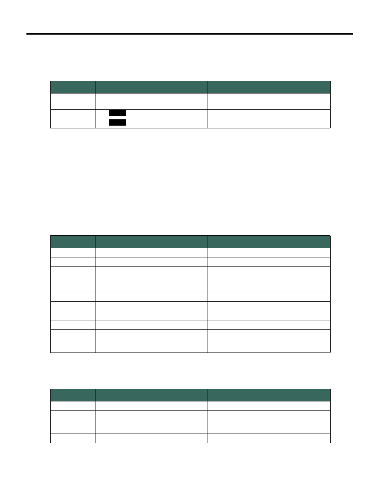
Monitoring and Troubleshooting Chapter 6
when there is network traffic. Table 6-2 shows the states of the Ethernet Status
LED.
Table 6-2 Ethernet Status LED States
Item No. LED Color LED Status Description
1None OFF
2
3
Yel low Solid Boot completed - Ethernet link good
Yel low Flashing Indicates Ethernet traffic
Operating system not running or OSA Remote
is not connected to the network.
Cyber LED The Cyber LED can be used to observe the loading and authentication sequence
of security keys and certificates during OSA Remote startup. During OSA
Remote operation, the Cyber LED indicates whether a connection request is
successful or unsuccessful. Unsuccessful connection requests could indicate
invalid keys or that OSA Remote security has been compromised. Table 6-3 lists
the Cyber LED states that can be observed during OSA Remote startup.
Table 6-4 lists the Cyber LED behavior during system operation.
Table 6-3 Cyber LED States During Startup
Item No. LED Color LED Status Description
1 None OFF Cyber LED is off during startup
2 Red Solid Operating system is running
3 Purple Solid
4 Purple Fast Flash No keys or certificates available to load
5 Blue Slow Flash Failed to validate customer certificates
6 Blue Medium Flash Loaded root certificate
7 Blue Fast Flash Failed to validate certificates
8 Blue Solid Key packages are being validated
9 Green Solid
OSA Remote is ready to load security keys and
certificates
Keys and certificates have been loaded. If the
keys cannot be loaded, the Cyber LED will
remain solid blue.
Table 6-4 Cyber LED Behavior During System Operation
Item No. LED Color LED Status Description
1 Green 3 Fast Flashes Authenticated connection
Connection failed. X.509 certificate did not
2 Orange 5 Fast Flashes
3 Cyan 2 Fast Flashes Unexpected connection attempt
10/11/18 Bedrock Secure OSA Remote User Manual - BRDOC020_001 59
authenticate due to an incorrect or missing
certificate. LED will return to green.
Page 68
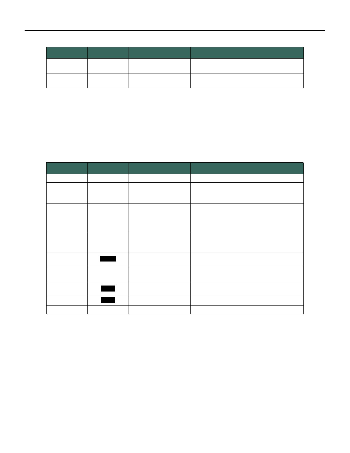
Chapter 6 Monitoring and Troubleshooting
Table 6-4 Cyber LED Behavior During System Operation
Item No. LED Color LED Status Description
4 Blue Flashing
5 Green Solid
There was an unexpected attempt to connect to
the OSA Remote.
Keys and certificates have been loaded. and
validated.
Channel LEDs Channel LEDs indicate the operating status of each OSA Remote I/O channel.
Channel LEDs are color-coded according to the configured operating mode of
each channel. In most cases, solid colored LEDs indicate normal operation while
flashing LEDs indicate an error condition. See Table 6-5.
Table 6-5 OSA Remote Channel LEDs
Item No. LED Color Operating Mode Description
1 None OFF Not configured (spare)
solid - normal operation
2 Green Analog 4-20 mA
3 Blue HART
4 Cyan 0-10 V
5
6 Purple NAMUR
7
8
9 Red Solid Failure on channel
Yel low Discrete Input/Output
White NAMUR
White Discrete Output fast flash - over range
slow flash - 4-20 mA under range
fast flash - 4-20 mA over range
off - no HART device communication
solid - device on scan
slow flash - 4-20 mA under range
fast flash - 4-20 mA over range
solid - normal operation
slow flash - under range
fast flash - over range
on indicates logical 1
off indicates logical 0
on indicates logical 1
off indicates logical 0
slow flash - under lower limit of NAMUR range
fast flash - over upper limit of NAMUR range
Storing Log Data in a Database
Bedrock Secure OSA Remotes provide a logging feature for recording significant
OSA Remote events and storing that information in a SQL database. A
Windows service named BedrockLogMonitor runs on the Bedrock Control
System workstation and periodically sends requests for log data to an OSA
Remote. The OSA Remote can then respond with messages that include its log
data. Log messages include information for events such as startup or shutdown,
changes in configuration, errors, and warnings. The BedrockLogMonitor service
uses an ODBC driver to write log entries to the database.
60 Bedrock Secure OSA Remote User Manual - BRDOC020_001 10/11/18
Page 69

Monitoring and Troubleshooting Chapter 6
The SQL database is selected by the user. The ODBC plug-in is provided by
the database vendor.
Note that in addition to storing log data in a database, log data can also be
accessed and saved using the following methods.
• Log data that is displayed in the Bedrock IDE OSA Remote Status
window can be written to a text file on the workstation. See “Status
Information”.
• Files containing log data can be transferred from the OSA Remote
flash memory to the workstation by using the file transfer capability
of the built in to the Bedrock IDE. See “Copying OSA Remote Log
Files”.
Default Configuration By default, OSA Remote log data is written to a local SQLite database. The
default location for the SQLite database is:
<IDE_install_dir>\Log Monitor\Log.db3
where <IDE_install_dir> is the installation location of the Bedrock IDE. By
default that location is:
C:\ProgramFiles (x86)\Bedrock IDE
If the Bedrock IDE is installed in a location other than the default location, the
database will be installed in that directory structure.
The remainder of this section describes the configuration needed for
connection to an ODBC database, logging service execution, and the format of
log data.
10/11/18 Bedrock Secure OSA Remote User Manual - BRDOC020_001 61
Page 70
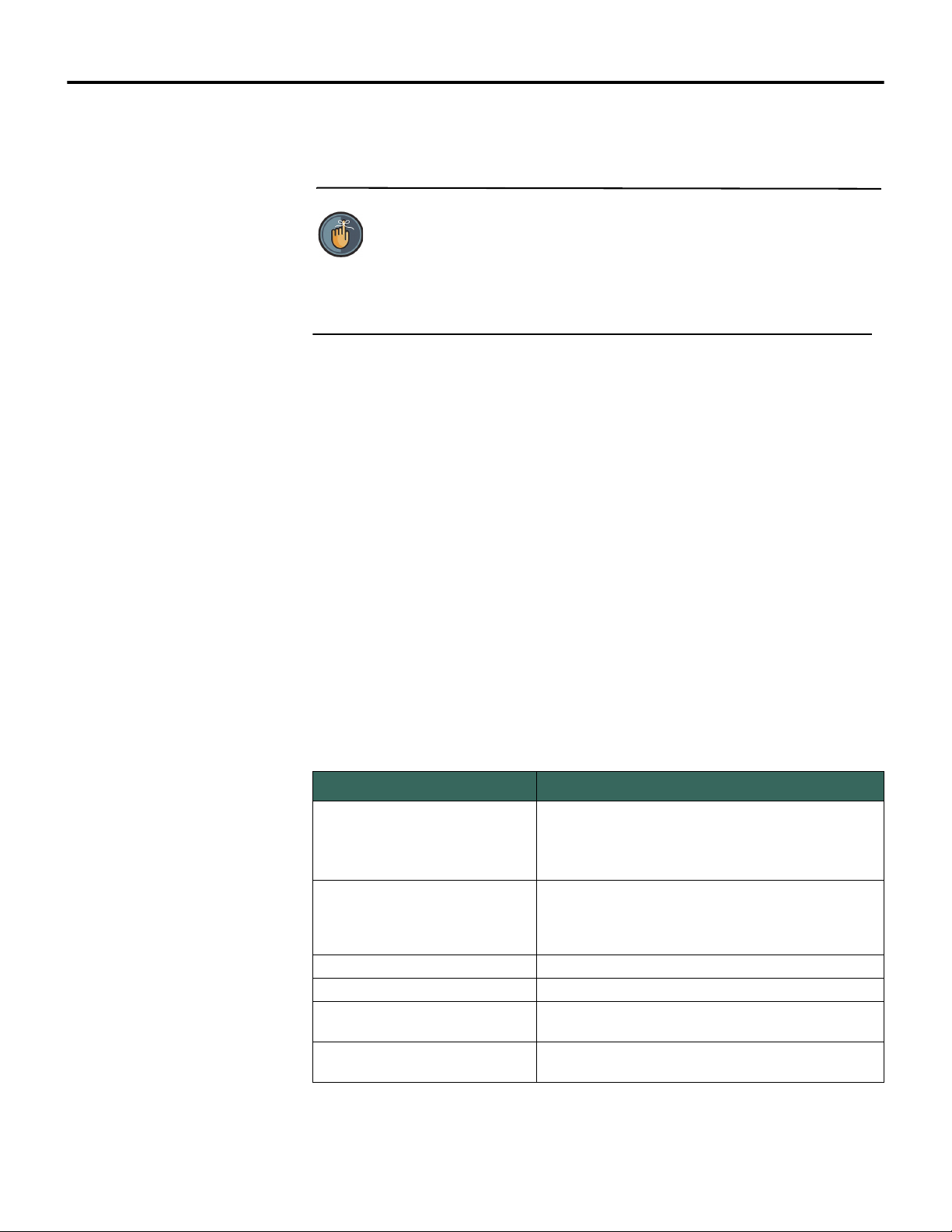
Chapter 6 Monitoring and Troubleshooting
ODBC Database Setup and Configuration
The following setup is required to prepare BedrockLogMonitor for receiving log
data from OSA Remotes.
Note
You must have administrative privileges to manually make changes to
the configuration file or the IDE.
• BedrockLogMonitor utilizes certain configurable parameters in the
XML configuration file
<IDE_install_dir>\Log Monitor\
BedrockLogMonitor.config.xml
These parameters, specified using XML elements, are described in
Table 6-6. A sample configuration file is shown in Figure 6-3. OSA
Remote information can be automatically added or removed from
the configuration when OSA Remotes are selected or deselected in
the Bedrock IDE (see below). Database connection information
(ODBCConnectionString and LogTableName) must be entered by
manually editing the configuration file.
Table 6-6 Logging Service Parameters
Parameter Description
Database connection information for the ODBC driver.
ODBCConnectionString
LogTableName
DeviceName The name of the device
DeviceType The type of the device (“CCM” for the OSA Remote)
DeviceSlotNum
IPAddress
Required for
information must be modified manually. By default, the
local database file (Log.db3) is specified.
Specifies the name of the table in the SQL database
where log entries will be written. This information must
be modified manually. By default, the table named
“log” is specified.
The slot number of the device. Always ‘1’ for the OSA
Remote.
One entry for each OSA Remote to be monitored.
Each entry will contain an IPv6 address.
BedrockLogMonitor. This
62 Bedrock Secure OSA Remote User Manual - BRDOC020_001 10/11/18
Page 71
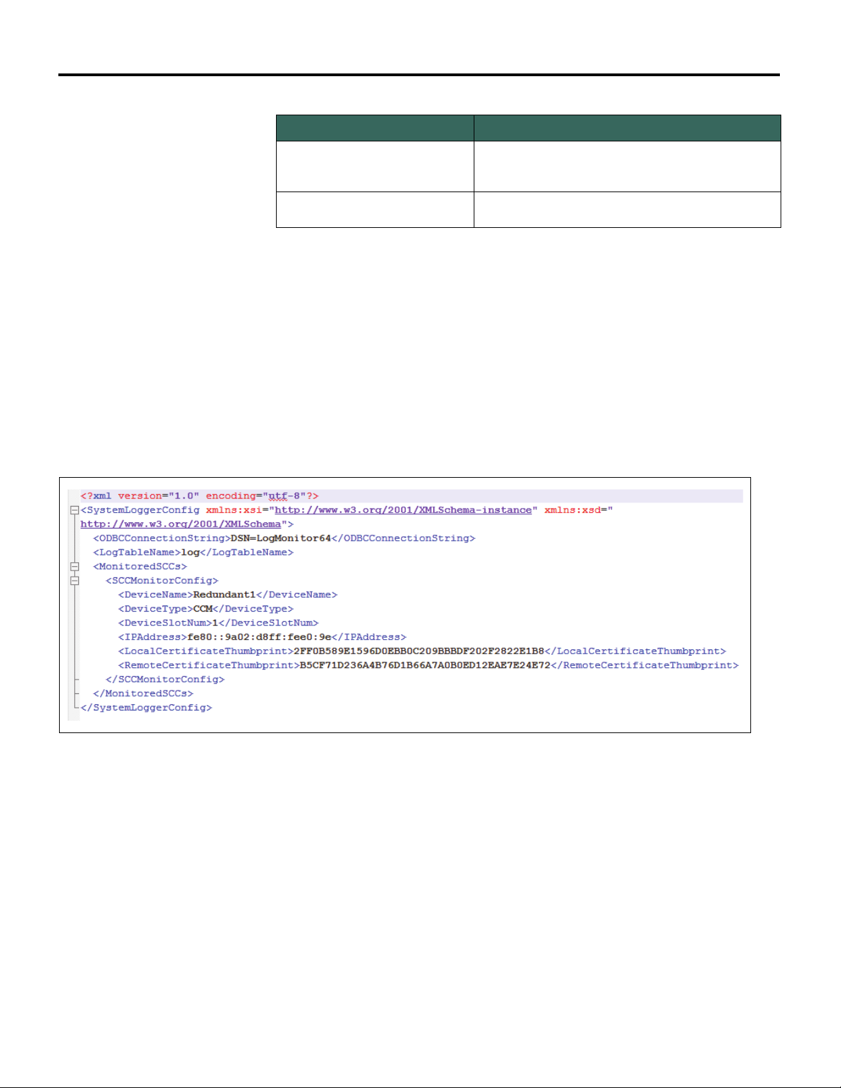
Monitoring and Troubleshooting Chapter 6
Table 6-6 Logging Service Parameters
Parameter Description
The thumb print of the certificate to use from the local
LocalCertificateThumbprint
RemoteCertificateThumbprint
machine key store that identifies the workstation to the
OSA Remote.
The expected thumb print of the certificate coming
from the OSA Remote.
• Figure 6-3 shows a sample XML configuration file for
BedrockLogMonitor. In the sample, a DSN (data source name) is
specified using the ODBConnectionString element. Use the
Windows ODBC Administrator tool to create a System DSN. On
64-bit machines, ensure that the 64-bit version of the tool is used to
create a System DSN (Figure 6-4). If connecting to a local database,
enter the database filename, e.g., Log.db3, in the
ODBConnectionString element.
Figure 6-3 Sample XML Configuration File
10/11/18 Bedrock Secure OSA Remote User Manual - BRDOC020_001 63
Page 72
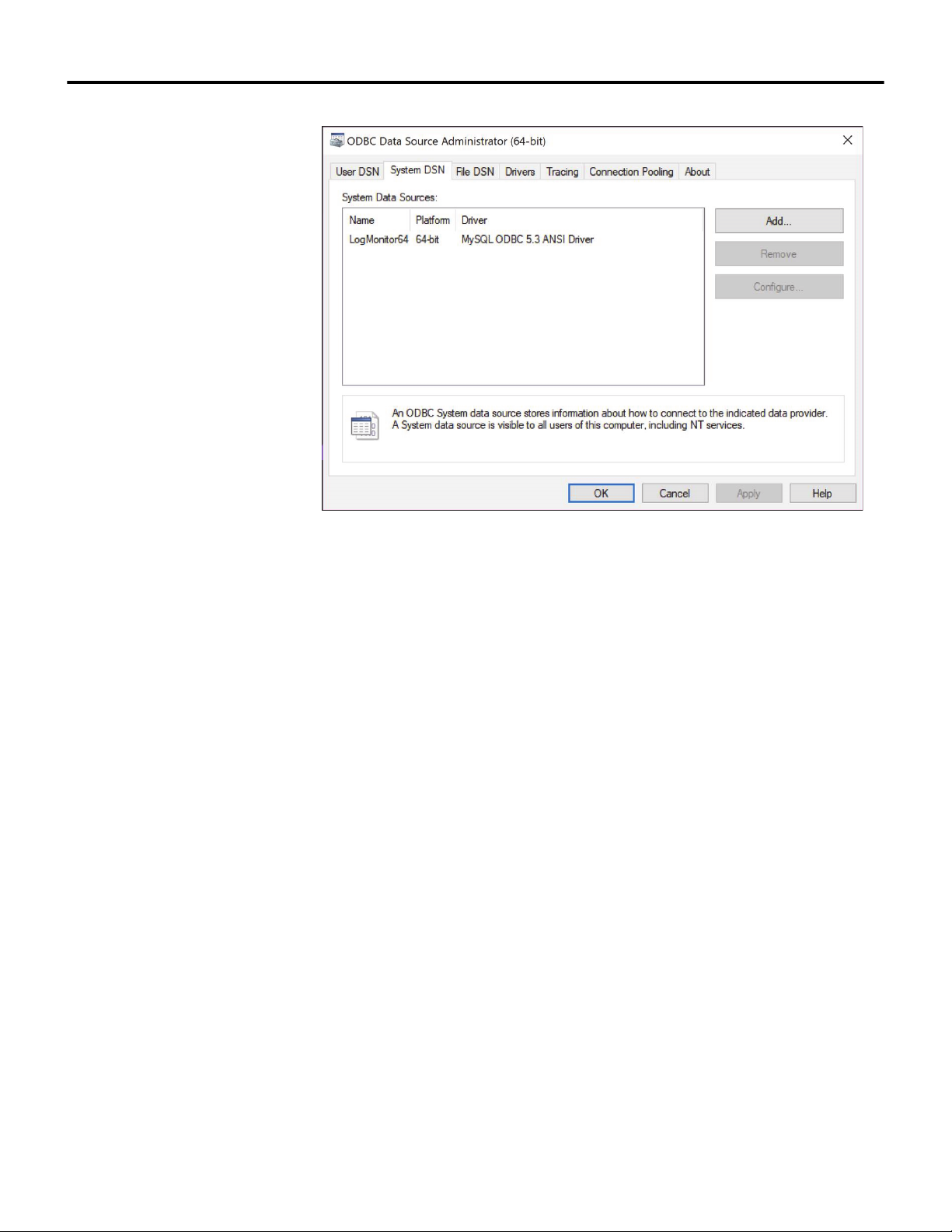
Chapter 6 Monitoring and Troubleshooting
Figure 6-4 Create System DSN
• Select Tools --> Device Management in the Bedrock IDE to select
the OSA Remotes from which BedrockLogMonitor will request log
records. Information specific to the selected OSA Remotes will be
updated in the configuration file.
• Since BedrockLogMonitor is started when Windows starts and since
the service will periodically check for changes in the configuration
file and reload the file if necessary, the service should not need to be
started manually. Starting the service manually can be done using
standard Windows procedures, e.g., Windows Control Panel,
entering
services.msc in the Windows Run dialog, using the net
command from the Windows command prompt, etc.
Logging Service Execution Once BedrockLogMonitor is started and configuration parameters are sent to
the OSA Remote, it will periodically send requests for log records via an Ethernet
socket to the OSA Remotes that were selected during setup and configuration.
The OSA Remote(s) will then respond with the requested log records and
BedrockLogMonitor will update the SQL database. Note that it is
BedrockLogMonitor that initiates the requests for log records. OSA Remotes
only send log records to BedrockLogMonitor in response to such a request.
Subsequently, if BedrockLogMonitor is not running, there is no impact to the
64 Bedrock Secure OSA Remote User Manual - BRDOC020_001 10/11/18
Page 73
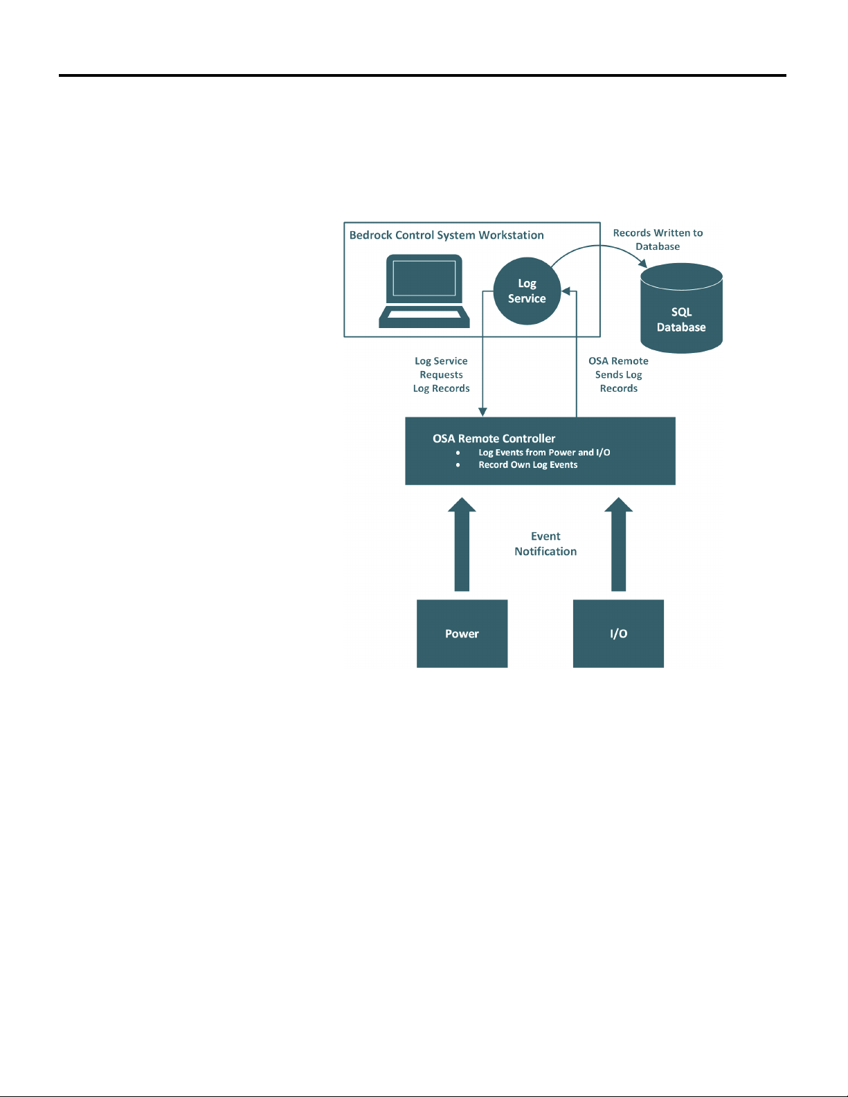
Monitoring and Troubleshooting Chapter 6
OSA Remote(s). The status of the BedrockLogMonitor service is available in the
Windows Event Viewer Application Log.
Figure 6-5 provides an overview of system logging in the Bedrock Control
System.
Figure 6-5 System Logging
10/11/18 Bedrock Secure OSA Remote User Manual - BRDOC020_001 65
Page 74

Chapter 6 Monitoring and Troubleshooting
The format of the log messages is shown in Table 6-7. Log messages can be read
from the database using the Ignition HMI software or any database client
software that is capable of reading a SQL database. See Appendix E, “Log
Messages” for a list of log messages generated by OSA Remotes.
Table 6-7 Log Entry Format
Database Field Name Descriptive Name Description / Possible Values
name OSA Remote Name
sltnum Slot Number always zero
bootcount Boot Count Number of times that the OSA Remote has been power cycled
msgnum Message Number
tm Time Stamp
msgtype Message Type
sio Module Type String that identifies the message source: controller, IO, or power.
chnum Channel Number Communication channel used by the module (1-5)
devtag Device Tag Manufacturer-supplied string containing module information
errcode Error Code Positive integer that identifies the error
msg Message Error message string
added Database Time Stamp
String that uniquely identifies the OSA Remote that is the source of the
log message
64-bit field. The lower 32 bits (0-31) contain the sequential message
number. The upper 32 bits (32-63) contain the boot count for the OSA
Remote.
Time that the OSA Remote received the message. Shown in the
following format:
YYYY-MM-DD HH:MM:SS:fff
String indicating the type of log message:
STARTUP
SHUTDOWN
CONFIG UPDATE
RUNTIME
WARNING
ERROR
Time that the entry was added to the database. Shown in the following
format:
YYYY-MM-DD HH:MM:SS:fff
Positive integer that identifies the error. The higher the number, the
greater the severity. Severity codes are as follows:
6 = CRITICAL- OSA Remote not booting, control program
stopped
severity Severity
originator Originator
5 = MAJOR - degraded service but system continues to operate
4 = MINOR - recoverable error has occurred
3 = WARNING - no errors, possible incorrect usage
2 = INFO - general information
1 = RESERVED
0 = UNKNOWN - contact technical support
Identifies the source (software component) that generated the log
message
66 Bedrock Secure OSA Remote User Manual - BRDOC020_001 10/11/18
Page 75
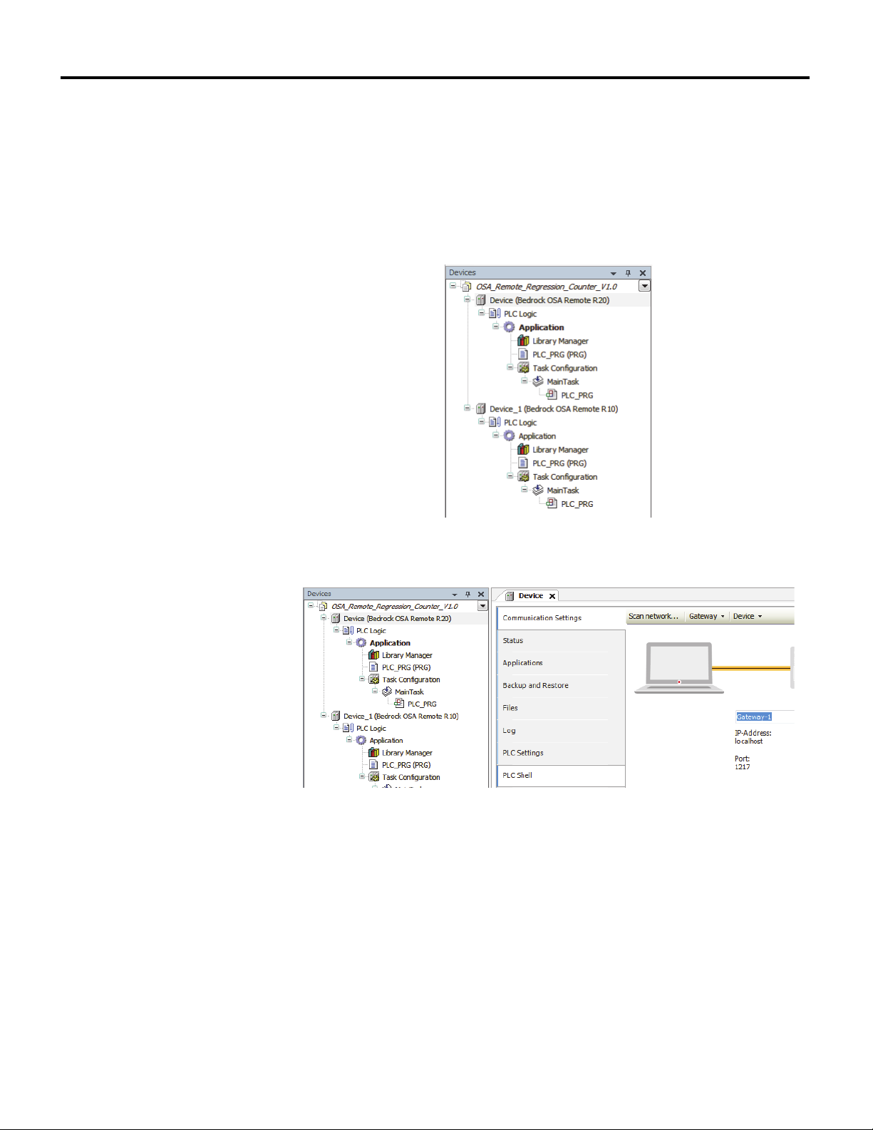
Monitoring and Troubleshooting Chapter 6
Copying OSA Remote Log Files
The Bedrock IDE provides the capability to copy log data from the OSA Remote
flash memory to the workstation’s file system. Log files can be accessed as
follows. Note that this sequence assumes that the user is logged into the OSA
Remote.
1. Double-click an OSA Remote in the Devices pane of the Bedrock IDE
(Figure 6-6). This will display the device editor (Figure 6-7).
Figure 6-6 Devices Pane
Figure 6-7 Devices Pane and Device Editor
2. Select the files tab in the device editor (Figure 6-8). Two lists will be
displayed. The list on the left will show the file system for the local
workstation. The list on the right will show the file system for the OSA
Remote flash memory.
10/11/18 Bedrock Secure OSA Remote User Manual - BRDOC020_001 67
Page 76
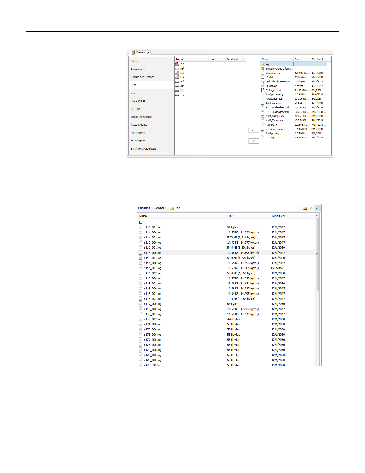
Chapter 6 Monitoring and Troubleshooting
3. Double-click the log folder in the right pane. A list of log files will be
displayed (Figure 6-9).
Figure 6-8 File Structures
Figure 6-9 Log Files
4. In the left pane (Figure 6-8), navigate to the local destination for the log
files. In the right pane, select the log files to copy.
5. Use the arrow buttons between the lists to copy the selected files to the
destination folder.
68 Bedrock Secure OSA Remote User Manual - BRDOC020_001 10/11/18
Page 77
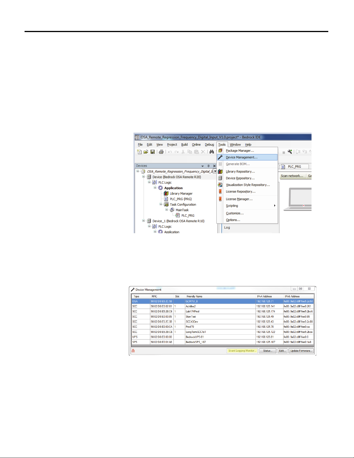
Monitoring and Troubleshooting Chapter 6
Note that the maximum amount of flash memory that can be used for storing
log files is 100 MB. Additionally, each log file can be no larger than 15 kB.
When the 100 MB limit is reached, the oldest log file will be overwritten.
Status Information Status and diagnostic information for an OSA Remote can be viewed by using
the Device Management feature in the Bedrock IDE. Access status information
as follows.
1. In the Bedrock IDE, select “Device Management...” from the Tools
menu as shown in Figure 6-10.
Figure 6-10 Select Device Management
2. In the Device Management window (Figure 6-11), select an OSA
Remote from the list of devices and then select the “Status...” button to
display the OSA Remote Status window (Figure 6-12).
Figure 6-11 Device Management Window
10/11/18 Bedrock Secure OSA Remote User Manual - BRDOC020_001 69
Page 78
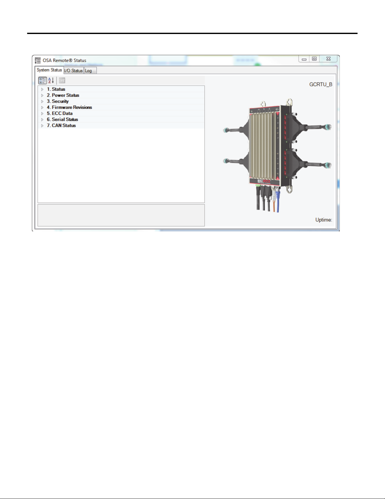
Chapter 6 Monitoring and Troubleshooting
Figure 6-12 OSA Remote Status
Tabs in the OSA Remote Status window (Figure 6-12) allow status and
diagnostic information to be displayed as follows.
• The System Status tab displays diagnostic information for OSA
Remote components and subsystems.
• The I/O Status tab displays information for each OSA Remote I/O
channel.
• The Log tab displays OSA Remote log entries. Selecting the “Log to
File” checkbox will cause log entries to be written to a local text file
while the OSA Remote Status window is open.
70 Bedrock Secure OSA Remote User Manual - BRDOC020_001 10/11/18
Page 79
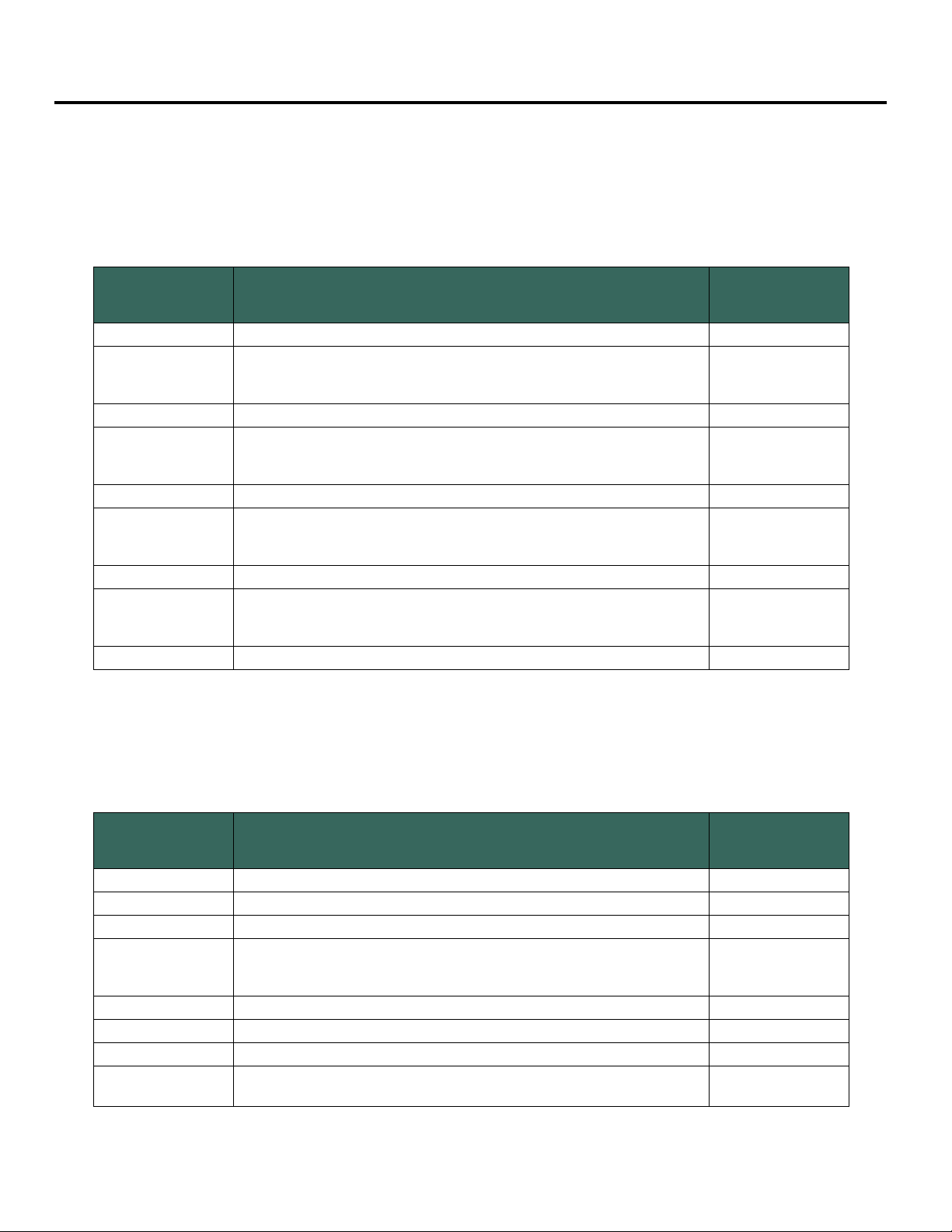
Appendix A
Part Numbers
Part numbers for the Bedrock Secure OSA Remote offerings are listed in
Table A-1.
Table A-1 OSA Remote Part Numbers
Model
Number
R10.8 Secure Universal 10 Channel Remote Controller; 8 GB Flash BROSAR10
Firmware upgrade at the factory or in the field for OSA Remote R10.8
R10.8X
R10.32 Secure Universal 10 Channel Remote Controller; 32 GB Flash BROSAR1H
R10.32X
R20.8 Secure Universal 20 Channel Remote Controller; 8 GB Flash BROSAR20
R20.8X
R20.32 Secure Universal 20 Channel Remote Controller; 32 GB Flash BROSAR2H
R20.32X
models. Enables user custom cyber root keys. Required to support secure
OPC UA and SCADA security.
Firmware upgrade at the factory or in the field for OSA Remote R10.32
models. Enables user custom cyber root keys. Required to support secure
OPC UA and SCADA security.
Firmware upgrade at the factory or in the field for OSA Remote R20.8
models. Enables user custom cyber root keys. Required to support secure
OPC UA and SCADA security.
Firmware upgrade at the factory or in the field for OSA Remote R20.32
models. Enables user custom cyber root keys. Required to support secure
OPC UA and SCADA security.
Bedrock Secure OSA Remote User Manual BRDOC020
Description
Part
Number
BROSAX10
BROSAX1H
BROSAX20
BROSAX2H
Additional part numbers for the components used with OSA Remotes are listed
in Table A-2.
Table A-2 Assembly Part Numbers
Model
Number
UC.1M Bedrock Universal Cable (1 Meter) BRUCB101
UC.3M Bedrock Universal Cable (3 Meters) BRUCB103
UC.5M Bedrock Universal Cable (5 Meters) BRUCB105
UC.XXM Bedrock Universal Cable (Custom Length)
UCD.1M Bedrock Universal I/O Termination Cable, 2 Connector, (1 Meter) BRUCB201
UCD.3M Bedrock Universal I/O Termination Cable, 2 Connector, (3 Meters) BRUCB203
UCD.5M Bedrock Universal I/O Termination Cable, 2 Connector, (5 Meters) BRUCB205
UCD.XXM
10/11/18 Bedrock Secure OSA Remote User Manual - BRDOC020_001 A-1
Bedrock Universal I/O Termination Cable, 2 Connector, (XX = Length of
Cable in Meters)
Description
BRUCB1XX
(XX = length of cable
in meters)
Part
Number
BRUCB2XX
Page 80
Appendix A Part Numbers
Table A-2 Assembly Part Numbers
Model
Number
PC.DC SPM DC Input Power Cable BRCBLDCP
PC.SER Universal Serial Communication Cable BRCBLSER
SFP-F Fiber Ethernet SFP Interface Module OP00003
SFP-C Copper Ethernet SFP Interface Module OP00008
Bedrock OSA Remote Mounting Stand BROSARMS
UTA.CP Universal Termination Assembly with PWR Dist BRUTA00P
UTA.CN Universal Termination Assembly with No PWR Dist BRUTA00N
Description
Part
Number
A-2 Bedrock Secure OSA Remote User Manual - BRDOC020_001 10/11/18
Page 81
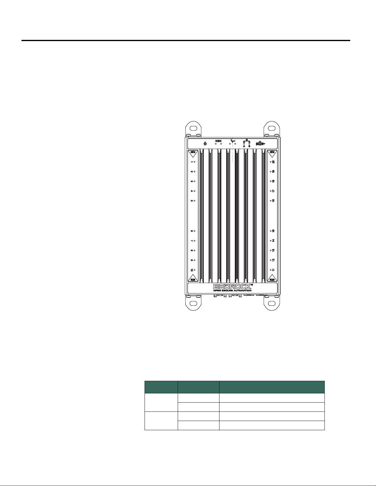
Appendix B
Channel 1
Channel 2
Channel 4
Channel 3
Channel 5
Channel 10
Channel 6
Channel 9
Channel 8
Channel 7
Channel 20
Channel 11
Channel 17
Channel 15
Channel 18
Channel 12
Channel 13
Channel 19
Channel 14
Channel 16
Wiring Diagrams and Pin Out Information
This appendix contains information for connecting the OSA Remote to field
devices. A table containing pin out information is provided along with wiring
diagrams that show channel wiring and configuration options. The location of the
connectors with channel numbers is shown in Figure B-1.
I/O Connector Pin Outs OSA Remote pin out information is shown in the following tables.
10/11/18 Bedrock Secure OSA Remote User Manual - BRDOC020_001 B-1
Pair No. Pin No. Function
PAIR 1
PAIR 2
Table B-1 OSA Remote Pin Outs for Channels 1-5
1 CHAN. 1 EXCITATION
2 CHAN. 1 ANALOG
3 CHAN. 1 RETURN
4 CHAN. 1 DISCRETE
Figure B-1 OSA Remote Connector Locations
Page 82
Appendix B Wiring Diagrams and Pin Out Information
Pair No. Pin No. Function
Table B-1 OSA Remote Pin Outs for Channels 1-5
PAIR 3
PAIR 4
PAIR 5
PAIR 6
PAIR 7
PAIR 8
PAIR 9
PAIR 10
5 CHAN. 2 EXCITATION
6 CHAN. 2 ANALOG
7 CHAN. 2 RETURN
8 CHAN. 2 DISCRETE
9 CHAN. 3 EXCITATION
10 CHAN. 3 ANALOG
11 CHAN. 3 RETURN
12 CHAN. 3 DISCRETE
13 CHAN. 4 EXCITATION
14 CHAN. 4 ANALOG
15 CHAN. 4 RETURN
16 CHAN. 4 DISCRETE
17 CHAN. 5 EXCITATION
18 CHAN. 5 ANALOG
19 CHAN. 5 RETURN
20 CHAN. 5 DISCRETE
Table B-2 OSA Remote Pin Outs for Channels 6-10
Pair No. Pin No. Function
PAIR 1
PAIR 2
PAIR 3
PAIR 4
PAIR 5
PAIR 6
PAIR 7
PAIR 8
PAIR 9
PAIR 10
1 CHAN. 6 EXCITATION
2 CHAN. 6 ANALOG
3 CHAN. 6 RETURN
4 CHAN. 6 DISCRETE
5 CHAN. 7 EXCITATION
6 CHAN. 7 ANALOG
7 CHAN. 7 RETURN
8 CHAN. 7 DISCRETE
9 CHAN. 8 EXCITATION
10 CHAN. 8 ANALOG
11 CHAN. 8 RETURN
12 CHAN. 8 DISCRETE
13 CHAN. 9 EXCITATION
14 CHAN. 9 ANALOG
15 CHAN. 9 RETURN
16 CHAN. 9 DISCRETE
17 CHAN. 10 EXCITATION
18 CHAN. 10 ANALOG
19 CHAN. 10 RETURN
20 CHAN. 10 DISCRETE
B-2 Bedrock Secure OSA Remote User Manual - BRDOC020_001 10/11/18
Page 83
Wiring Diagrams and Pin Out Information Appendix B
Table B-3 OSA Remote Pin Outs for Channels 11-15
Pair No. Pin No. Function
PAIR 1
PAIR 2
PAIR 3
PAIR 4
PAIR 5
PAIR 6
PAIR 7
PAIR 8
PAIR 9
PAIR 10
1 CHAN. 11 EXCITATION
2 CHAN. 11 ANALOG
3 CHAN. 11 RETURN
4 CHAN. 11 DISCRETE
5 CHAN. 12 EXCITATION
6 CHAN. 12 ANALOG
7 CHAN. 12 RETURN
8 CHAN. 12 DISCRETE
9 CHAN. 13 EXCITATION
10 CHAN. 13 ANALOG
11 CHAN. 13 RETURN
12 CHAN. 13 DISCRETE
13 CHAN. 14 EXCITATION
14 CHAN. 14 ANALOG
15 CHAN. 14 RETURN
16 CHAN. 14 DISCRETE
17 CHAN. 15 EXCITATION
18 CHAN. 15 ANALOG
19 CHAN. 15 RETURN
20 CHAN. 15 DISCRETE
Table B-4 OSA Remote Pin Outs for Channels 16-20
Pair No. Pin No. Function
PAIR 1
PAIR 2
PAIR 3
PAIR 4
PAIR 5
PAIR 6
PAIR 7
10/11/18 Bedrock Secure OSA Remote User Manual - BRDOC020_001 B-3
1 CHAN. 16 EXCITATION
2 CHAN. 16 ANALOG
3 CHAN. 16 RETURN
4 CHAN. 16 DISCRETE
5 CHAN. 17 EXCITATION
6 CHAN. 17 ANALOG
7 CHAN. 17 RETURN
8 CHAN. 17 DISCRETE
9 CHAN. 18 EXCITATION
10 CHAN. 18 ANALOG
11 CHAN. 18 RETURN
12 CHAN. 18 DISCRETE
13 CHAN. 19 EXCITATION
14 CHAN. 19 ANALOG
Page 84
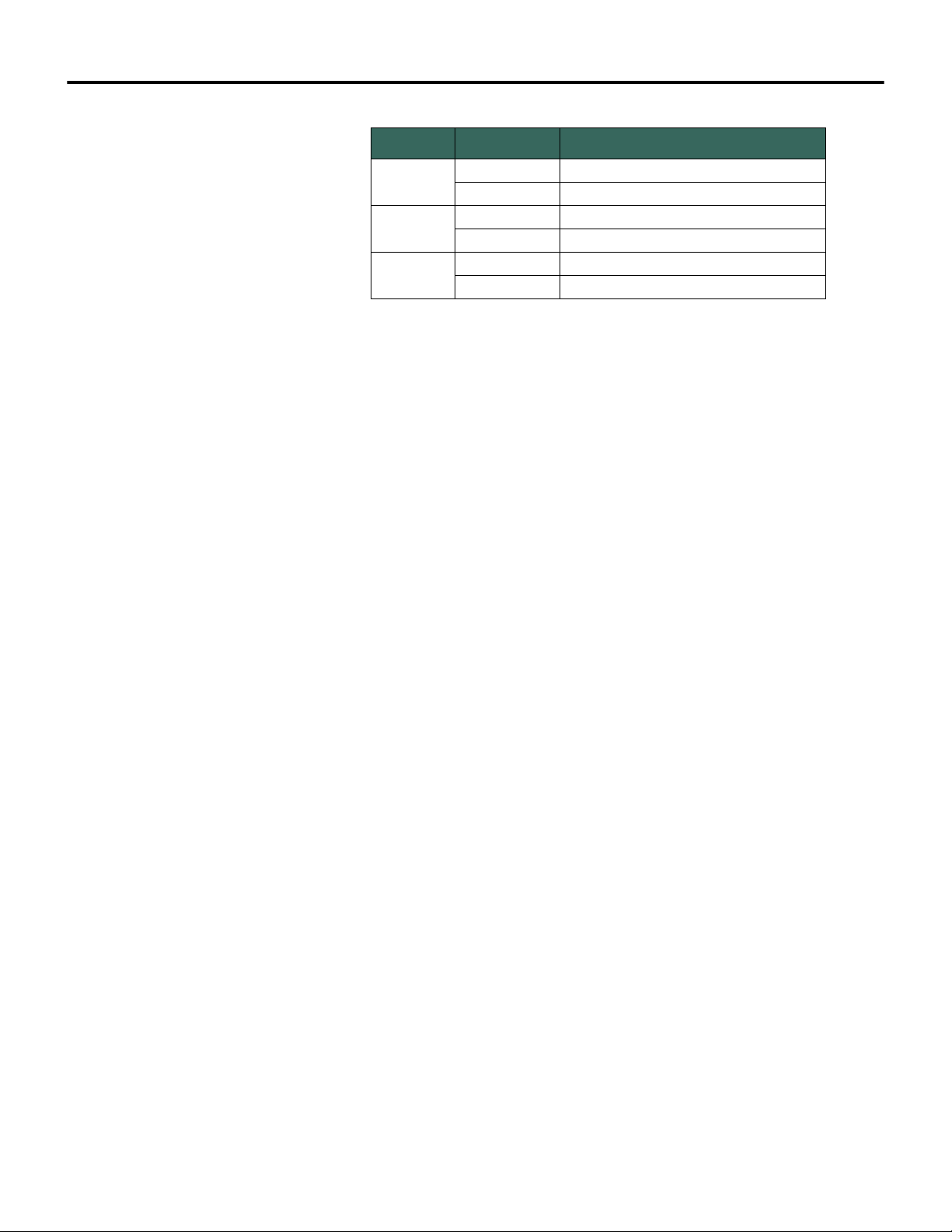
Appendix B Wiring Diagrams and Pin Out Information
Pair No. Pin No. Function
Table B-4 OSA Remote Pin Outs for Channels 16-20
PAIR 8
PAIR 9
PAIR 10
15 CHAN. 19 RETURN
16 CHAN. 19 DISCRETE
17 CHAN. 20 EXCITATION
18 CHAN. 20 ANALOG
19 CHAN. 20 RETURN
20 CHAN. 20 DISCRETE
B-4 Bedrock Secure OSA Remote User Manual - BRDOC020_001 10/11/18
Page 85
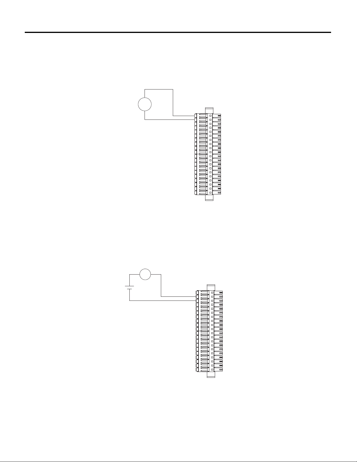
Wiring Diagrams and Pin Out Information Appendix B
Ch 5, 10, 15, 20
}
Ch 4, 9, 14, 19
}
Ch 3, 8, 13, 18
}
Ch 2, 7, 12, 17
}
Ch 1, 6, 11, 16
}
LOOP POWERED
TRANSMITTER
T
Ch 5, 10, 15, 20
}
Ch 4, 9, 14, 19
}
Ch 3, 8, 13, 18
}
Ch 2, 7, 12, 17
}
Ch 1, 6, 11, 16
}
+
LOOP POWERED
TRANSMITTER
POWER SUPPLY
-
T
I/O Connector Wiring Diagrams
The following figures are the wiring diagrams for connecting the OSA Remote
to field devices.
Figure B-2 OSA Remote: 4-20 mA Internal Loop Powered Transmitter
Figure B-3 OSA Remote: 4-20 mA External Loop Powered Transmitter
10/11/18 Bedrock Secure OSA Remote User Manual - BRDOC020_001 B-5
Page 86
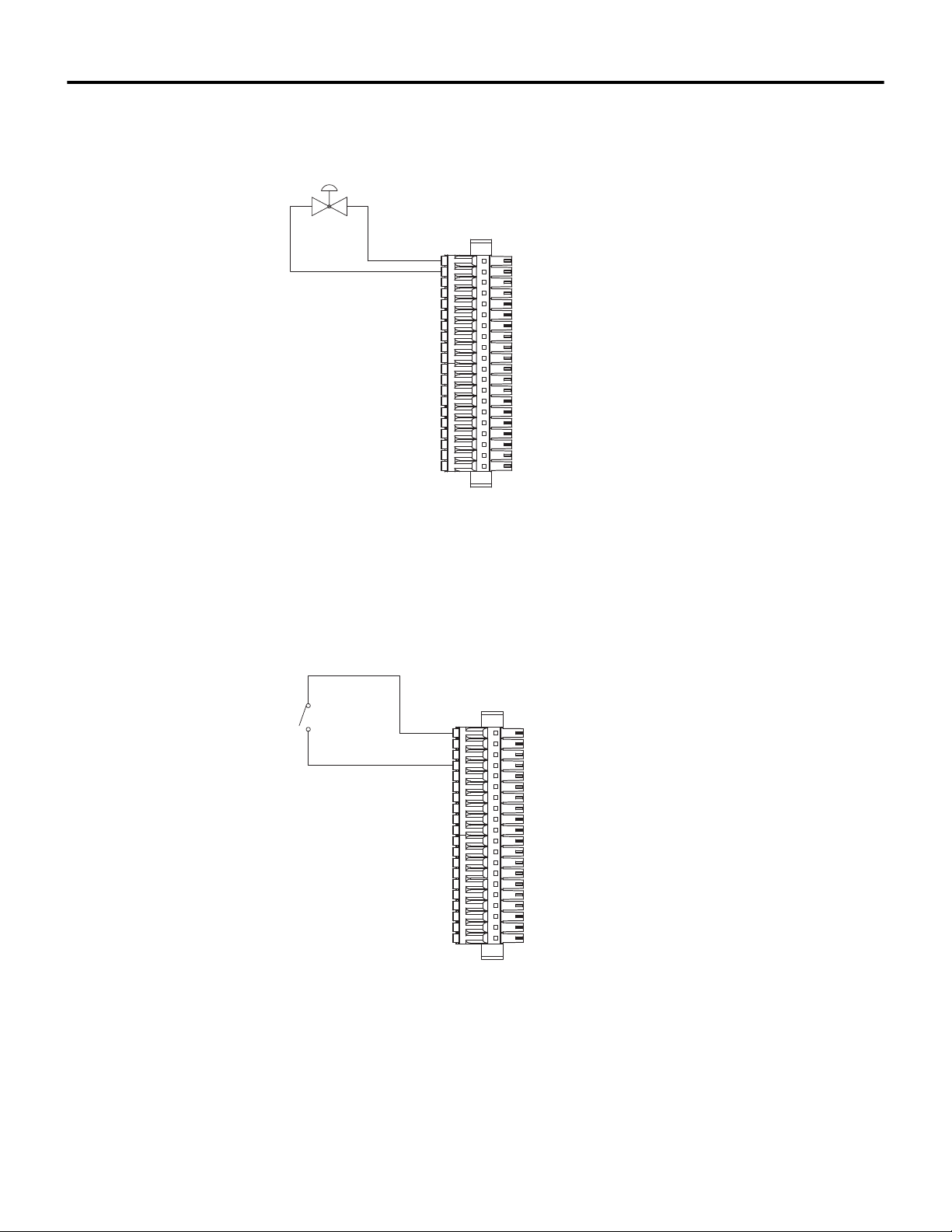
Appendix B Wiring Diagrams and Pin Out Information
Ch 5, 10, 15, 20
}
Ch 4, 9, 14, 19
}
Ch 3, 8, 13, 18
}
Ch 2, 7, 12, 17
}
Ch 1, 6, 11, 16
}
Ch 5, 10, 15, 20
}
Ch 4, 9, 14, 19
}
Ch 3, 8, 13, 18
}
Ch 2, 7, 12, 17
}
Ch 1, 6, 11, 16
}
Figure B-4 OSA Remote: 4-20 mA Output with Internal Readback
Figure B-5 OSA Remote: Discrete Input Contact Closure
B-6 Bedrock Secure OSA Remote User Manual - BRDOC020_001 10/11/18
Page 87
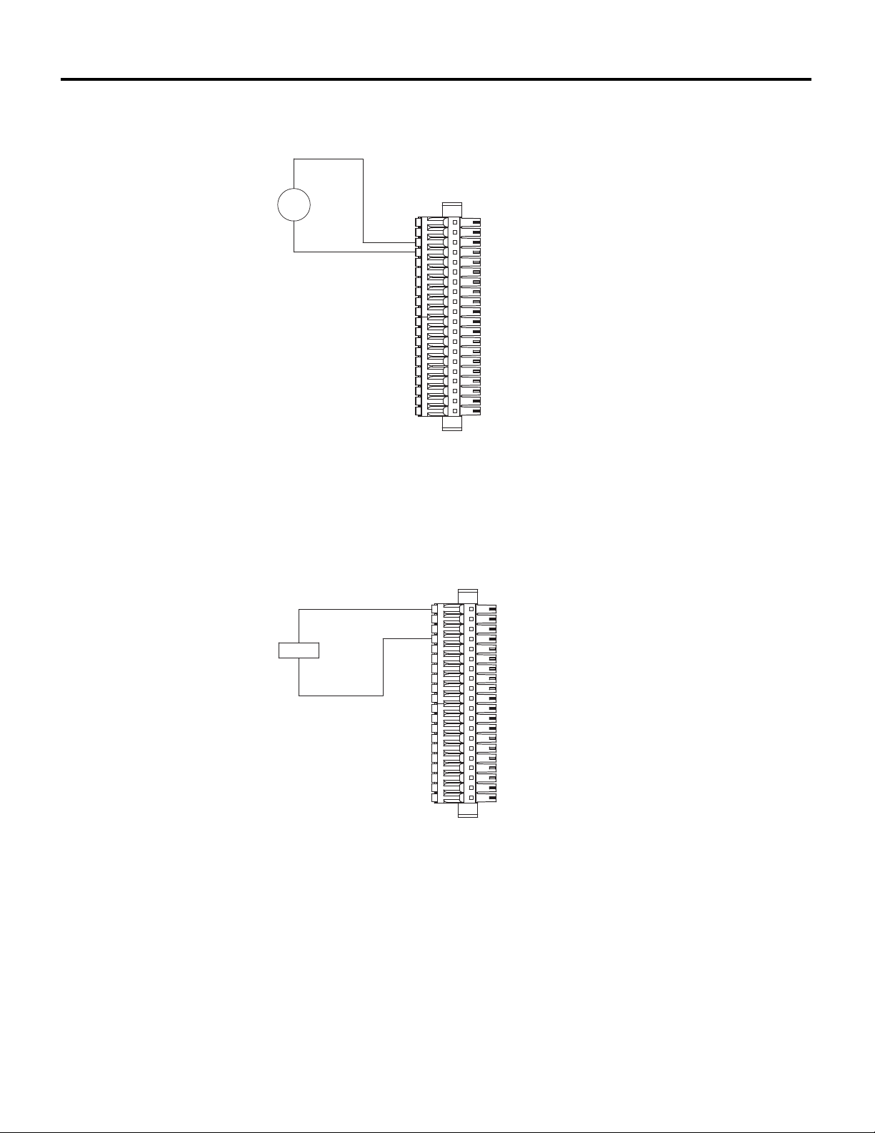
Wiring Diagrams and Pin Out Information Appendix B
Ch 5, 10, 15, 20
}
Ch 4, 9, 14, 19
}
Ch 3, 8, 13, 18
}
Ch 2, 7, 12, 17
}
Ch 1, 6, 11, 16
}
V
-
+
Ch 5, 10, 15, 20
}
Ch 4, 9, 14, 19
}
Ch 3, 8, 13, 18
}
Ch 2, 7, 12, 17
}
Ch 1, 6, 11, 16
}
LOAD
Figure B-6 OSA Remote: Discrete Input Voltage Monitor
Figure B-7 OSA Remote: Discrete Output Internal Excitation
10/11/18 Bedrock Secure OSA Remote User Manual - BRDOC020_001 B-7
Page 88
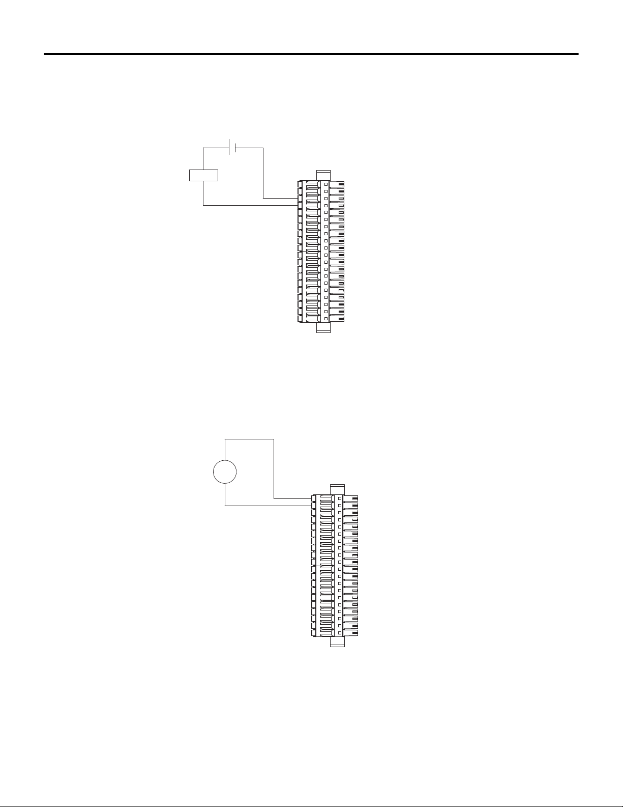
Appendix B Wiring Diagrams and Pin Out Information
Ch 5, 10, 15, 20
}
Ch 4, 9, 14, 19
}
Ch 3, 8, 13, 18
}
Ch 2, 7, 12, 17
}
Ch 1, 6, 11, 16
}
LOAD
+
-
POWER
SUPPLY
Ch 5, 10, 15, 20
}
Ch 4, 9, 14, 19
}
Ch 3, 8, 13, 18
}
Ch 2, 7, 12, 17
}
Ch 1, 6, 11, 16
}
T
+
-
NAMUR
SENSOR
Figure B-8 OSA Remote: Discrete Output External Excitation
B-8 Bedrock Secure OSA Remote User Manual - BRDOC020_001 10/11/18
Figure B-9 OSA Remote: NAMUR Sensor
Page 89
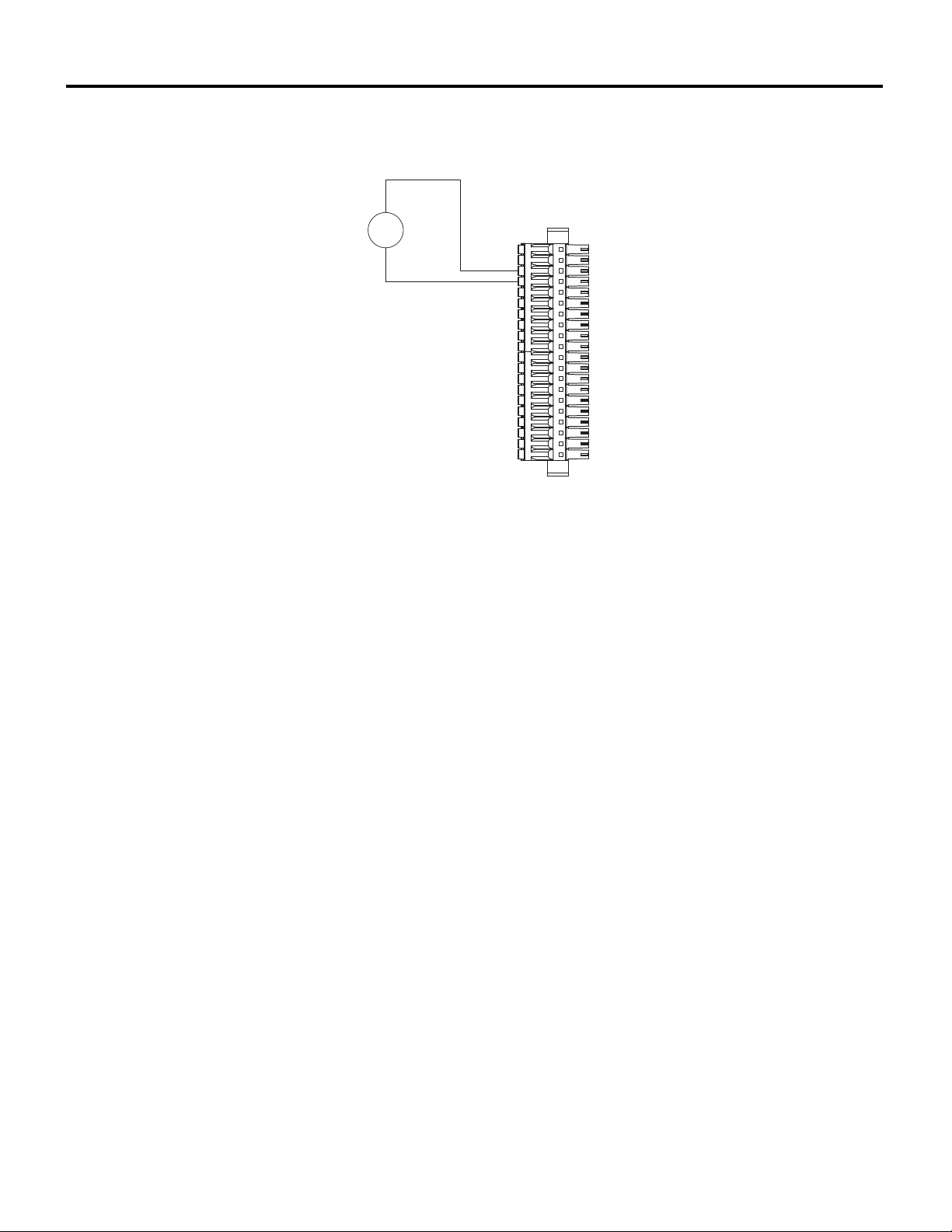
Wiring Diagrams and Pin Out Information Appendix B
Ch 5, 10, 15, 20
}
Ch 4, 9, 14, 19
}
Ch 3, 8, 13, 18
}
Ch 2, 7, 12, 17
}
Ch 1, 6, 11, 16
}
V
-
+
EXTERNAL
VOLTAGE
SOURCE
Figure B-10 OSA Remote: 0-10 Volt Input
10/11/18 Bedrock Secure OSA Remote User Manual - BRDOC020_001 B-9
Page 90
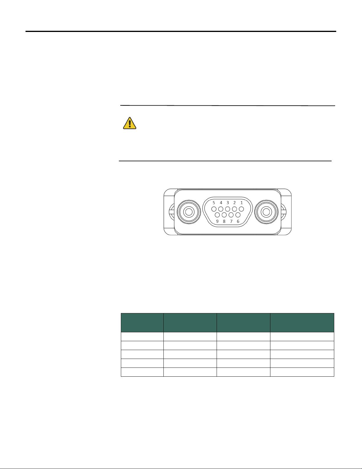
Appendix B Wiring Diagrams and Pin Out Information
Serial Port Wiring The Universal Serial Communication Cable is used for serial communication
between an OSA Remote and field devices. One end of the cable has a Micro-D
connector for connecting to the OSA Remote serial port. The other end has a
9-pin female D-Sub connector (the same as can be found on a standard PC) for
connecting to serial devices. The pin out for each connector is the same. The
Micro-D connector with pin numbers is shown in Figure B-11.
Important
Note that a shielded cable tied to the OSA Remote enclosure is required to
comply with product safety certifications.
Figure B-11 Serial Cable Pin Numbering
The pin out information for each serial operating mode is shown in Table B-5.
Note that each channel is isolated and pin 5 must be connected in all modes.
Table B-5 Serial Communication Pin Out Information
Pin Number RS-232 RS-485
2 RXD RXD+
3 TXD DATA+ TXD+
5GND GND GND
7RTSDATA- TXD-
8 CTS RXD-
RS-422 /
RS-485 Full Duplex
B-10 Bedrock Secure OSA Remote User Manual - BRDOC020_001 10/11/18
Page 91
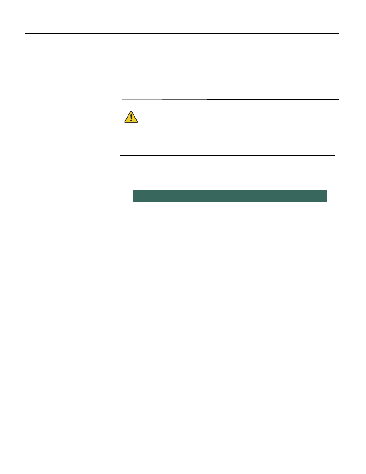
Wiring Diagrams and Pin Out Information Appendix B
CAN Bus Port Wiring The Universal Serial Communication Cable can also be used for communication
with CAN bus devices. The cable’s Micro-D connector connects to the CAN bus
port on the OSA Remote. The 9-pin female D-Sub connector connects to CAN
bus field devices. The pin out for each connector is the same. The Micro-D
connector is shown in Figure B-11.
Important
Note that a shielded cable tied to the OSA Remote enclosure is required to
comply with product safety certifications.
The pin out information for the CAN bus port is shown in Table B-6.
Table B-6 CAN Bus Communication Pin Out Information
Pin Number Signal Signal Description
2 CAN_L CAN Low
3 CAN_GND Ground
7 CAN_H CAN High
9 CAN_V+ Power Presence Input
10/11/18 Bedrock Secure OSA Remote User Manual - BRDOC020_001 B-11
Page 92
Appendix C
OSA Remote Specifications
The following are the specifications for the Bedrock Secure OSA Remote.
General Specifications See Table C-1 for general specifications for the OSA Remote, i.e., specifications
that are not specific to analog, discrete, or NAMUR operation. Those
specifications are presented in subsequent tables.
Table C-1 OSA Remote General Specifications
Specification Value
Processor Dual-Core ARM Cortex processor
RAM 512 MB ECC RAM
Flash Memory
MRAM 8 kB
Control Cycle Time 3 ms
RTOS Green Hills INTEGRITY™
Open Control Package Support Bedrock IDE
Ethernet Communication
IP Stack Dual-mode IPv4/IPv6
Power Requirement 9-30 V, 25 W max. power
Interface
8 GB, standard
32 GB, optional
1 Gbit Dual SFP (Fiber or Copper)
transceiver slots
Ten or twenty isolated and independent
channels. Each channel can be configured
for analog input or output, discrete input or
output, or as a NAUMUR input depending
on the operating mode
C-1 Bedrock Secure OSA Remote User Manual - BRDOC020_001 10/11/18
Page 93

Specification Value
Operating Modes
OSA Remote Specifications Appendix C
Table C-1 OSA Remote General Specifications
• 4-20 mA analog input (loop current max.
of 25 mA) with HART
• 4-20 mA analog output with readback
with HART
• 4-20 mA analog input (loop current max.
of 25 mA) without HART
• 4-20 mA analog output with readback
without HART
• internally powered discrete output with
readback (24 V excitation, maximum
current of 25 mA)
• externally powered discrete output with
readback (maximum current of 1 A)
• NAMUR
• 0-10 V voltage input
• discrete input
Channels may also be configured as a spare
Serial Communication Standards RS-232, RS-422, RS-485
Serial Connections 1
CAN Bus Connections 1
Power Consumption 24 watts
Power Dissipation 15 watts
The channels are galvanically isolated
from each other and galvanically isolated
from ground.
Operating Temperature -40°C to 80°C
Storage Temperature -40°C to 85°C
PWB Max. Operating Temperature 130°C
Relative Humidity 5% to 95% non-condensing
Time Stamp Resolution 10 ns
Time Stamp Accuracy ±0.5 ms
Real-Time Clock super-capacitor backed, can hold for 15
Channel to channel: 500 V
Channel to ground: 500 V
days
10/11/18 Bedrock Secure OSA Remote User Manual - BRDOC020_001 C-2
Page 94
Appendix C OSA Remote Specifications
Physical Characteristics The OSA Remote has the physical characteristics listed in Table C-2.
Table C-2 OSA Remote Physical Characteristics
Specification Value
Height 226 mm (8.90 inches)
Width 137 mm (5.39 inches)
Depth 59 mm (2.32 inches)
Weight ~1587 g (3.5 pounds)
Aluminum 6063-T5
Housing Front/Back
Housing Top/Bottom/Sides
Electroless Nickel Plating
(note that the front of the unit contains the
LEDs)
Aluminum 6061-T6
Black Anodized
Field Wiring Requirements
Input / Output Specifications
Bedrock Automation provides a 20-pin connector (Phoenix Contact part
number 1835325) for connection to field devices. The connector has been tested
according to UL 1059, Use Group C (industrial applications without
restrictions).
Cabling between the OSA Remote and field devices must meet the following
requirements:
• Minimum 22 AWG, maximum 16 AWG, shielded
• Maximum temperature of 105°C
• UL Type CM or AWM21894
• C(UL) Type CMG FT4 (for use in Canada)
• oil and gas resistant
The Bedrock Universal Cable is available as an accessory for connecting the
OSA Remote to field devices. It is available in standard lengths of 1, 3, or 5
meters. It can also be ordered in custom lengths. See Table A-2 for model and
part number information.
Each OSA Remote I/O channel can be independently configured for one of the
operating modes described in Table C-1. Depending upon the mode selected,
the following functionality is available:
• 4-20 mA input or output with or without HART
• discrete input with programmable debounce enables the OSA
Remote to count debounced pulses in addition to the input state
C-3 Bedrock Secure OSA Remote User Manual - BRDOC020_001 10/11/18
Page 95
OSA Remote Specifications Appendix C
• counter mode (discrete input) where the OSA Remote accumulates
high-speed pulses up to 100 kHz
• frequency mode (discrete input) where the OSA Remote provides
accurate frequency measurement from 10 Hz to 100 kHz
• interface to NAMUR sensor for monitoring low-level current
• 0-10 V voltage input.
See Table C-3 for OSA Remote specifications that are specific to analog
operation.
Table C-3 OSA Remote Analog Specifications
Specification Value
Loop Compliance Voltage 18 V DC minimum at 22 mA
Current Inputs Sense Resistor 250 Ω, software selectable
Analog Output Load Resistance Minimum 250 Ω
Analog Output Load Resistance Maximum 750 Ω
4-20 mA Analog Input Current Accuracy ±0.03% of full-scale at 23°C
Analog Input Voltage Accuracy ±0.035% of full-scale at 23°C
Actual Input Range (current input) 3.25 mA - 22 mA
Actual Output Range (current output) 3.25 mA - 22 mA
Actual Input Range (voltage input) 0.1 V - 12 V
Voltage Input Impedance 20 kΩ
Analog Output Accuracy
Excitation
Temperature Coefficient 50 ppm/°C
Input Resolution 20 bits
Output Resolution 14 bits
Non-linearity Included in accuracy
±0.035% of full-scale (between 4 mA and
20 mA) at 23°C
Programmable:
Loop Voltage Mode: 21.6 V @ 22 mA
The OSA Remote supports the following discrete input types:
• voltage monitor
• contact sense.
The following discrete output types are supported:
• externally sourced discrete outputs
• internally sourced discrete outputs.
10/11/18 Bedrock Secure OSA Remote User Manual - BRDOC020_001 C-4
Page 96
Appendix C OSA Remote Specifications
OSA Remote specifications related to each of the discrete input and output
types are presented in the following tables.
Table C-4 lists OSA Remote specifications that are specific to voltage monitor
inputs.
Table C-4 Specifications for Voltage Monitor Inputs
Specification Value
Input Impedance (discrete input voltage)
Input Frequency Range 10 Hz to 100 kHz
Filter/Debounce Time Programmable 0-255 ms
Frequency Accuracy ±0.035% of full-scale
20 kΩ
Table C-5 lists OSA Remote specifications that are specific to contact sense
inputs.
Table C-5 Specifications for Contact Sense Inputs
Specification Value
Maximum Voltage on Excitation 25 V
Filter/Debounce Time Programmable 0-255 ms
Frequency Accuracy ±0.035% of full-scale
Table C-6 lists OSA Remote specifications that are specific to externally
sourced discrete outputs.
Table C-6 Specifications for Externally Sourced Discrete Outputs
Specification Value
Maximum On Current 1 amp
Maximum Switching Voltage 30 V
Programmable Overcurrent Shutoff Latch-off or back-off retry
3-255 ms
•Back-off versus latch-off
•Back-off and retry count setting
Overcurrent Delay (Retry Period)
Inductive Loads
Blanking Time 3 ms
C-5 Bedrock Secure OSA Remote User Manual - BRDOC020_001 10/11/18
After an overcurrent condition occurs, each
channel can either stay latched off or backoff and retry. If back-off and retry is chosen,
the number of retries can be selected. The
total number of turn-on attempts is one plus
the number of configured retries.
Outputs require protective diodes or metaloxide varistors when connected to an
inductive load
Page 97
OSA Remote Specifications Appendix C
Table C-6 Specifications for Externally Sourced Discrete Outputs
Specification Value
On State Resistance < 0.25 Ω
Off State Resistance 20 kΩ
Maximum Off Voltage 30 V DC
Overcurrent Limit Soft-selectable up to 1.0 amps
Discrete Output Current Accuracy 1.5% of full scale
Table C-7 lists OSA Remote specifications that are specific to internally
sourced discrete outputs.
Table C-7 Specifications for Internally Sourced Discrete Outputs
Specification Value
Maximum Voltage on Excitation 25 V
Maximum Current 25 mA
Discrete Output Current Accuracy 1.5% of full scale
See Table C-8 for OSA Remote specifications that are specific to NAMUR
operation.
Table C-8 NAMUR Specifications
Specification Value
NAMUR Impedance 1 kΩ
NAMUR Sensor Failure < 0.2 mA
NAMUR Off 1.1 mA
NAMUR On 2.0 mA
NAMUR Voltage 7-12 V
10/11/18 Bedrock Secure OSA Remote User Manual - BRDOC020_001 C-6
Page 98
Appendix C OSA Remote Specifications
Power Specifications The OSA Remote accepts a 9-30 V DC power input. Table C-9 lists the
electrical specifications for the OSA Remote power input.
Table C-9 Power Input Specifications
Specification Value
Input Voltage Range (DC)
Input Fuse (DC) 4 A
Input Protection Transient Surge Protection
Clamp Voltage 33 V
Voltage Monitor Input Accuracy 1%
9-30 V DC - the OSA Remote turns on at
10 V and off below 9 V
C-7 Bedrock Secure OSA Remote User Manual - BRDOC020_001 10/11/18
Page 99
Appendix D
HART Variables
The Bedrock Secure OSA Remote uses the HART variables listed in this
appendix. HART runtime data is listed in Table D-1. HART configuration data
is listed in Table D-2. The HART variable names in the two tables correspond to
the description fields displayed on the HART Device Data I/O Mapping tab in
the Bedrock IDE.
The bit definitions for the Communication Status field in Table D-1 are listed in
Table D-3. The bit definitions for the Device Status field in Table D-1 are listed
in Table D-4.
In addition to the HART runtime and configuration data, the Bedrock IDE
displays the HART device state for each channel. See Table D-5 for the HART
device states.
The HART Device Data Parameters tab in the Bedrock IDE provides
a HART Device Address parameter for each channel. Entering a value of 0-15
specifies an address of a HART device. A value of 16 is used for auto-scan.
Setting a channel for auto-scan will cause the OSA Remote to scan from address
0-15. The first HART device found will be used for that channel.
Table D-1 HART Runtime Data
HART Variable Name Size Type/Range
Loop Current 4 bytes Float
Primary Value Unit Code 2 bytes 1-255
Primary Value 4 bytes Float
Secondary Value Unit Code 2 bytes 1-255
Secondary Value 4 bytes Float
Tertiary Value Unit Code 2 bytes 1-255
Tertiary Value 4 bytes Float
Quaternary Value Unit Code 2 bytes 1-255
Quaternary Value 4 bytes Float
Communication Status 1 byte 8 bit field
Device Status 1 byte 8 bit field
10/11/18 Bedrock Secure OSA Remote User Manual - BRDOC020_001 D-1
Page 100

Appendix D HART Variables
Table D-2 HART Configuration Data
HART Variable Name Size Type/Range
Device Tag 12 bytes Null terminated character string
Device Descriptor 16 bytes Null terminated character string
Date 12 bytes Null terminated character string
Device Message 32 bytes Null terminated character string
Long Tag 32 bytes Null terminated character string
PV Upper Range 4 bytes Float
PV Lower Range 4 bytes Float
Damping Value 4 bytes Float
Sensor Serial Number 4 bytes Integer Number
Device ID 4 bytes Integer Number
Upper Sensor Limit 4 bytes Float
Lower Sensor Limit 4 bytes Float
Minimum Span 4 bytes Float
Private Label Distributor Code 1 byte Integer Number
Sensor Unit Code 1 byte 1-255
Number of Preambles 1 byte Integer Number
Range Units 1 byte 1-255
Poll Address 1 byte Integer Number
Manufacturer ID 1 byte 1-255
Device Type 1 byte Integer Number
Universal Command Revision 1 byte Integer Number
Device-specific Command
Revision
Software Revision 1 byte Integer Number
Hardware Revision 1 byte Integer Number
1 byte Integer Number
Table D-3 Communication Status Bit Descriptions
Communication Status Bit Description
Reserved 0
Buffer Overflow Message buffer has overflowed
Reserved 1
Longitudinal Parity Error Parity error of a serial byte
Frame Error Message framed incorrectly
Overrun Error Serial controller chip has overrun buffer
Vertical Parity Error Parity error of transmitted message
Communications Error Generic communications failure
D-2 Bedrock Secure OSA Remote User Manual - BRDOC020_001 10/11/18
 Loading...