

Page 1

KL3351
1-Channel Resistor Bridge Input Terminal
Configuration Instructions
Version 2.2
2006-10-23
Page 2

Contents
Contents
1. Foreword 3
Notes on the documentation 3
Safety Instructions 4
2. Technical data 5
3. Description of functions 6
4. Terminal configuration 7
5. Register description 8
General register description 8
Terminal-specific register description 11
Register communication KL3351 12
6. Annex 15
Mapping in the bus coupler 15
Table of the register 17
7. Support and Service 18
Beckhoff Headquarters 18
2 KL3351
Page 3

Foreword
Foreword
Notes on the documentation
This description is only intended for the use of trained specialists in control and automation engineering
who are familiar with the applicable national standards. It is essential that the following notes and
explanations are followed when installing and commissioning these components.
Liability Conditions
The responsible staff must ensure that the application or use of the products described satisfy all the
requirements for safety, including all the relevant laws, regulations, guidelines and standards.
The documentation has been prepared with care. The products described are, however, constantly under
development. For that reason the documentation is not in every case checked for consistency with
performance data, standards or other characteristics. None of the statements of this manual represents a
guarantee (Garantie) in the meaning of § 443 BGB of the German Civil Code or a statement about the
contractually expected fitness for a particular purpose in the meaning of § 434 par. 1 sentence 1 BGB. In
the event that it contains technical or editorial errors, we retain the right to make alterations at any time
and without warning. No claims for the modification of products that have already been supplied may be
made on the basis of the data, diagrams and descriptions in this documentation.
Delivery conditions
In addition, the general delivery conditions of the company Beckhoff Automation GmbH apply.
Copyright
©
This documentation is copyrighted. Any reproduction or third party use of this publication, whether in
whole or in part, without the written permission of Beckhoff Automation GmbH, is forbidden.
KL3351 3
Page 4
Foreword
i
Safety Instructions
State at Delivery
All the components are supplied in particular hardware and software configurations appropriate for the
application. Modifications to hardware or software configurations other than those described in the
documentation are not permitted, and nullify the liability of Beckhoff Automation GmbH.
Description of safety symbols
The following safety symbols are used in this documentation. They are intended to alert the reader to the
associated safety instructions..
This symbol is intended to highlight risks for the life or health of personnel.
Danger
This symbol is intended to highlight risks for equipment, materials or the
Attention
environment.
This symbol indicates information that contributes to better understanding.
Note
4 KL3351
Page 5
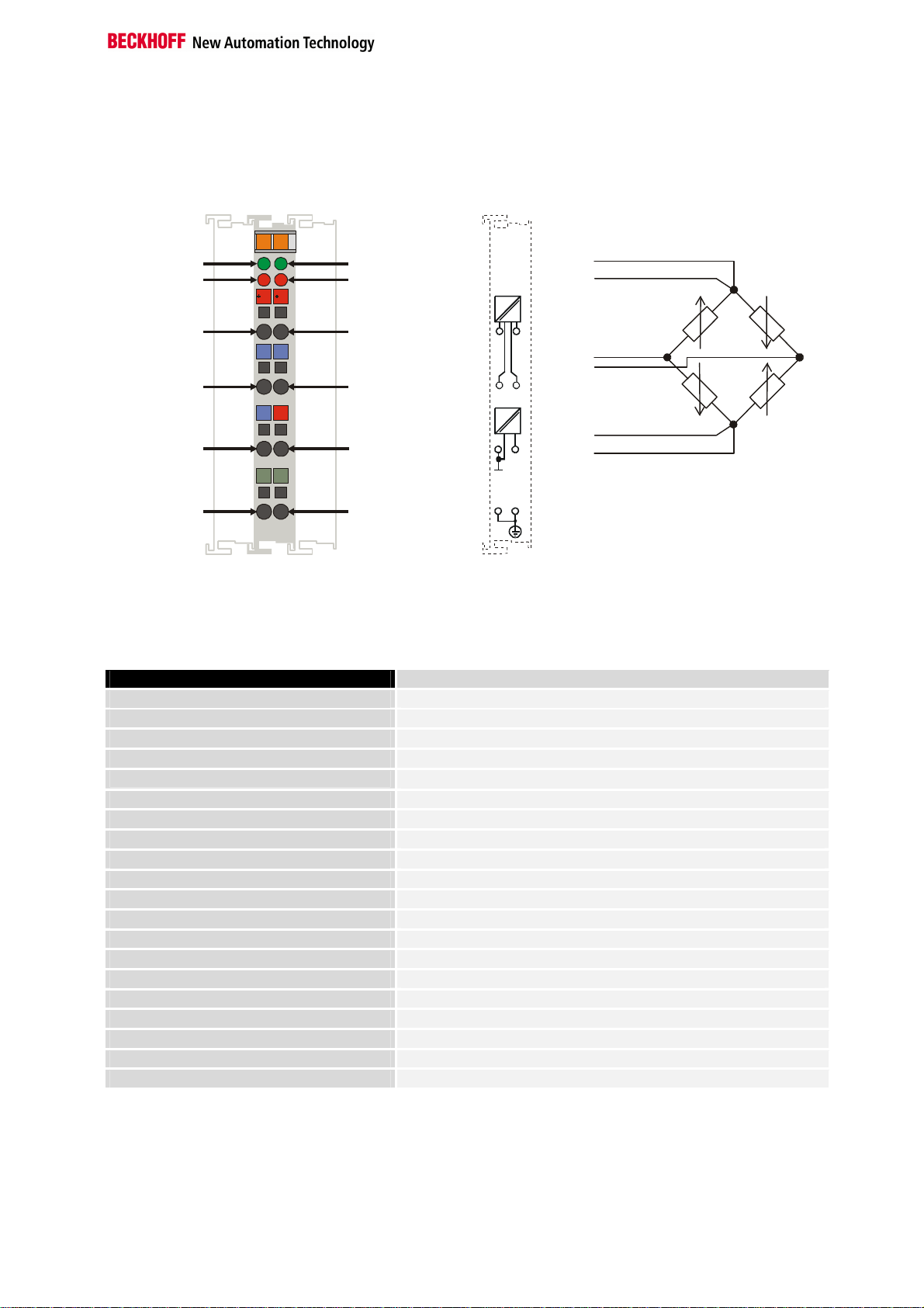
The power supply Uv can be obtained from the terminal
+Uref
+Uref
- Uref
- Uref
Technical data
13
14
RUN - LED1
Error - LED1
A
B
C
D
U
r
U
D
RUN - LED2
Error - LED2
Technical data
+U
V
+ U
- U
-U =0V
V
Shield
D
D
1
2
3
4
5
-U
r
-U
D
6
-U
V
+ V
U
7
S
S
8
+ U
- U
+U =5V
Shield
Top View Contacts Contact Assembly
Technical data KL3351
Number of inputs
Power supply
Signal voltage UD
Signal voltage U
Internal resistance
Power supply UV
Resolution
Conversion time
Measuring error (total measuring range)
Filter
Electrical isolation
Current consumption from K-Bus
Bit width in the process image
Operating temperature
Storage temperature
Relative humidity
Vibration/shock resistance
EMC resistance Burst / ESD
Installation position
Type of protection
ref
ref
V
+U
- U
- U
D
+U
D
- U
- U
D
V
D
V
+U
V
or can be feed in external.
The terminal supplies 5 V.
The maximum input voltage Uref is limited to 10 V.
2, for one resistor bridge
via the K-Bus
-16 mV ... +16 mV, configurable
-10 V ... +10 V, configurable
ref
> 200 kΩ (U
5 V, 20 mA
16 bits
< 250 ms. Configurable
< ± 0.1% (of the upper range value)
50 Hz, configurable
500 Vrms (K-Bus / signal voltage )
65 mA typ.
I: 2 x 16 bits data (2 x 8 bits control/status)
0°C ... +55°C
-25°C ... +85°C
95%, no condensation
conforms to IEC 68-2-6 / IEC 68-2-27
conforms to EN 50082 (ESD, Burst) / EN 50081
any
IP20
ref
), > 1 MΩ (UD)
KL3351 5
Page 6

Description of functions
Description of functions
The KL3351 analogue input terminal permits direct connection of a
resistance bridge. The bridge voltage, UD, and the supply voltage, U
ref
, to
the bridge are digitised with 16 bits resolution, and are transmitted over an
electrically isolated channel to the supervising automation system. The
input channels are available in the form of two 16 bit values for further
processing. The resulting measurement can be calculated from the
formula: measurement = UD / U
. Precise acquisition of the supply voltage
ref
along with the bridge voltage compensates for long-term and temperature
drift.
Output of the measurement
The bridge voltage between +UD and –UD is output with a resolution of
500 nV/digit, so that 10 mV corresponds to an output value of 20000 in the
data bytes D0 and D1 of channel 1.
The supply voltage for the bridge is output with a resolution of 500 µV/digit,
so that 10 V corresponds to the output value 20000 in the data bytes D0
and D1 of channel 2.
The resolution can be adjusted by means of gain register R38.
Example
A load cell was connected to the KL3351 in an experimental test bed.
The load cell was fed with the terminal’s 5 V supply voltage (UV), while the
reference voltage (U
) and the bridge voltage were captured with the U
ref
ref
and UD channels respectively.
Technical data for the load cell:
5 kg = 2 mV/V
The weight is calculated as follows:
Weight = UD / U
* 5/0.002 [kg]
ref
Bridge supply
If the internal voltage supply is overloaded (I_load > 20 mA), it is
recommended that a KL9505 or a KL9510 be used.
LED display
The four LEDs indicate the operating state of the associated terminal
channels.
Green LEDs: RUN
On: normal operation
Off: Watchdog-timer overflow has occurred. If no process data is
transmitted to the bus coupler for 100 ms, the green LEDs go out.
Red LEDs: ERROR
Error LED1: outside the acceptable range for the signal voltage (UD), or
broken wire
Error LED2: outside the acceptable range for the reference voltage (U
)
ref
6 KL3351
Page 7

Offset Terminal1 Channel1 = 0
Offset Terminal2 Channel1 = 4
Offset Terminal2 Channel2 = 8
User data allocation depending
To the bus terminal
Offset Terminal1 Channel1 = 0
Offset Terminal1 Channel2 = 3
Offset Terminal2 Channel1 = 6
To the bus terminal
Beckhoff Lightbus
Coupler BK2000
Terminal configuration
The terminal can be configured and parametrized by way of the internal
register structure.
Each terminal channel is mapped in the bus coupler. The terminal’s data is
mapped differently in the bus coupler’s memory depending on the type of
the bus coupler and on the set mapping configuration (eg.Motorola / Intel
format, word alignment,...). For parametrization of a terminal, the control
/status byte must also be mapped.
In the case of the Beckhoff Lightbus coupler BK2000, the control /status
byte is always mapped besides the data bytes. It is always in the low byte
at the offset address of the terminal channel.
Beckhoff-Lightbus
bus coupler
BK2000
The terminal is
mapped in the
bus coupler.
Terminal configuration
C/S
Data H Data L
C/S
Data LData H
C/S
D1 - 1
D1 - 0
0
D0 - 1
C/S - 1
D0 - 0
C/S - 0
on mapping
KL3351
Profibus Coupler BK3000
LH
K-Bus
In the case of the Profibus coupler BK3000, for which terminal channels
the control /status byte is also to be inserted must be defined in the master
configuration .If the control /status byte is not evaluated, the KL3351
occupies 4 bytes of input data (2 bytes of user data per channel).
Profibus bus coupler
BK3000
The terminal is
mapped in the
bus coupler.
Data L
Data H
C/S
D0 - 1
D1 - 1
C/S - 1
D0 - 0
D1 - 0
C/S - 0
0
The control-/status byte
must be inserted for
parameterization.
KL 3351 Channel 2
KL 3351 Channel1
KL3351 7
K-Bus
Page 8

Register description
Offset Terminal1 Channel1 = 0
Offset Terminal2 Channel1 = 4
Offset Terminal1 Channel2 = 2
Offset Terminal2 Channel1 = 6
To the bus terminal
i
Interbus Coupler BK4000
By default, the Interbus coupler BK4000 maps the KL3351 with 4 bytes of
input data (2 bytes of user data per channel). Parametrization via the field
bus is not possible. The KS2000 software is required for configuration if
use is to be made of the control /status byte.
Interbus bus coupler
BK4000
The terminal is
mapped in the
bus coupler.
The control/status byte
must be inserted for
Data H
Data L
Data H
Data L
Data H
D0 - 1
D1 - 1
D0 - 0
D1 - 0
0
parameterization (KS2000).
K-Bus
Other bus couplers and
further information
Note
Parametrization with the
KS2000 software
You will find further information on the mapping configuration of bus
couplers in the annex of the respective bus coupler manual under the
heading of “Configuration of masters”.
The annex contains an overview of the possible mapping configurations
depending on the adjustable parameters.
Parametrization operations can be carried out independantly of the field
bus system using the Beckhoff KS2000 configuration software via the
serial configuration interface in the bus coupler.
Register description
8 KL3351
The complex terminals can be adjusted to different operating modes or
functionalities. The “ general description of register “ describes the contents
of the registers, which are identical for all complex terminals.
The terminal-specific registers are explained in the section following to it.
The access to the internal registers of the terminal is described in the
section “ register communication “.
General register description
Complex terminals that possess a processor are capable of bidirectionally
ex-changing data with the higher-level control system. Below, these
terminals are referred to as intelligent bus terminals. They include the
analog inputs (0-10V, -10-10V, 0-20mA, 4-20mA), the analog outputs (010V, -10-10V, 0-20mA, 4-20mA), serial interface terminals (RS485, RS232,
TTY, data transfer terminals), counter terminals, encoder interfaces, SSI
interfaces, PWM terminals and all other parametrizable terminals.
Page 9

Register description
Internally, all intelligent terminals possess a data structure that is identical
in terms of it’s essential characteristics. This data area is organized in
words and embraces 64 memory locations. The essential data and
parameters of the terminal can be read and adjusted by way of the
structure. Function calls with corresponding parameters are also possible.
Each logical channel of an intelligent terminal has such a structure
(therefore, 4-channel analog terminals have 4 register sets.
This structure is broken down into the following areas:
(You will find a list of all registers at the end of this documentation).
Area Address
Process variables
Type registers
Manufacturer parameters
User parameters
Extended user area
0-7
8-15
16-30
31-47
48-63
Process variables R0 – R7: Registers in the terminal’s internal RAM:
The process variables can be used in additional to the actual process
image and their functions are specific to the terminal.
R0 – R5: These registers have a function that depends on the terminal
type.
R6: Diagnostic register
The diagnostic register may contain additional diagnostic information. In
the case of serial interface terminals, for example, parity errors that have
occurred during data transfer are indicated.
R7: Command register
High-Byte_Write = function parameter
Low-Byte _Write = function number
High-Byte _Read = function result
Low-Byte_ Read = function number
Type registers R8 – R15 Registers in the terminal’s internal ROM der Klemme
The type and system parameters are programmed permanently by the
manufacturer and can only be read by the user but cannot be modified.
R8: Terminal type:
The terminal type in register R8 is needed to identify the terminal.
R9: Software version X.y
The software version can be read as an ASCII character string.
R10: Data length
R10 contains the number of multiplexed shift registers and their length in
bits.
The bus coupler sees this structure.
R11: Signal channels
In comparison with R10, the number of logically existing channels is
located here. For example, one physically existing shift register may
consist of several signal channels.
R12: Minimum data length
The respective byte contains the minimum data length of a channel to be
transferred. If the MSB is set, then the control/status byte is not necessarily
needed for the function of the terminal and, with appropriate configuration
of the coupler, is not transferred to the control system.
KL3351 9
Page 10

Register description
i
R13: Data type register
Data type register
0x00
0x01
0x02
0x03
0x04
0x05
0x06
0x07
0x08
0x11
0x12
0x13
0x14
0x15
0x16
Terminal without valid data type
Byte array
1 byte n bytes structure
Word array
1 byte n words structure
Double word array
1 byte n double words structure
1 byte 1 double word structure
1 byte 1 double word structure
Byte-array with a variable logical channel length
1 byte n bytes structure with a variable logical channel
length (eg 60xx)
Word-array with a variable logical channel length
1 byte n words structure with a variable logical channel
length
Double word array with a variable logical channel length
1 byte n double words structure with a variable logical
channel length
R14: not used
R15: Alignment bits (RAM)
The analog terminal is set to a byte limit in the terminal bus with the alignment bits.
Manufacturer parameters R16 – R30 is the area of the “Manufacturer parameters” (SEEROM)
The manufacturer parameters are specific to each terminal type. They are
programmed by the manufacturer but can also be modified from the control
system. The manufacturer parameters are stored permanently in a serial
EEPROM and are therefore not destroyed by power failures.
These registers can only be modified after setting a code word in R31.
User parameters
R31 – R47 “Application parameters” area (SEEROM)
The application parameters are specific to each terminal type. They can be
modified by the programmer. The application parameters are stored
permanently in a serial EEPROM in the terminal and cannot be destroyed
by power failures. The user area is write protected over a Codeword.
R31: Code word-register in the RAM
The code word 0x1235 must be entered here to enable modification of
Note
parameters in the user area. Write-protection is set if a different value is
entered in this register. When write protection is inactive, the code word is
returned during reading of the register. The register contains the value zero
when write protection is active.
R32: Feature-register
This register defines the operating modes of the terminal. For example, a
user-specific scaling can be activated for the analog I/O’s.
R33 – R47
Registers that depend on the terminal type
Extended application area R47 – R63
These registers have not yet been implemented.
10 KL3351
Page 11

Terminal-specific register description
Process variables R0: Unfiltered ADC value X_R
This register contains the unfiltered ADC value of the connected element
according to (Gl. 0.1)
R1-R5: No function
R6: Diagnostic register
High byte: not used
Low byte: status byte
Manufacturer parameter R17: Offset hardware B_a
16 bit signed integer
This register is used for offset compensation of the terminal.
Register value approx. 0x0000
R18: Gain hardware A_a
This register is used for gain compensation of the terminal.
Register value approx. 0x3D4X
R19: Manufacturer offset B_h
16 bit signed integer [0x0000]
This register contains the offset of the manufacturer’s linearisation
equation. The linearisation equation is activated by way of R32.
R20: Manufacturer scaling A_h
16 bit signed integer *2^-8 [0x00A0]
This register contains the scale factor of the manufacturer’s linearisation
equation. The linearisation equation is activated by way of R32.
Application parameter R32: Feature register:
[0x0004]
The feature register specifies the terminal’s operating mode.
Feature Bit No.
Bit 11-6
Bit 15-12
R33: User offset B_w
16 bit signed integer
This register contains the offset of the user linearisation equation. The
linearisation equation is activated by way of R32.
R34: User scaling A_w
16 bit signed integer *2^-8
This register contains the scale factor of the user linearisation equation.
Bit 0
Bit 1
Bit 2
Bit 3
Bit 4
Bit 5
1 User scaling (R33, R44) active [0]
1 Manufacturer scaling (R19, R20) active [0]
1 Watchdog timer active [1]
1 Sign / amount representation [0]
- Not used, don’t change
1 activate Filter constant in R37 [0]
- Not used, don't change
Operating mode
1111 Voltage output [1111]
others Reserved
Register description
Description of the operating mode
The watchdog timer is switched on by default.
Sign / amount representation is active instead
of twos-complement representation. (-1 =
0x8001)
KL3351 11
Page 12

Register description
The linearisation equation is activated by way of R32.
R35: Reserved
R36: Reserved
R37: Filter constant
[0x0000]
The filter constant is taken over after a power on RESET by the terminal.
Filter constants: First notch [Hz] Conversion time [ms]
0x0000 25 250
0x50 100 65
0xA0 50 125
0x140 25 250
0x280 12.5 500
R38: Gain setting [0x0010]
Various amplification factors are set with this register, permitting different
measurement resolutions.
R38 Gain UD[µV]/Digit
0x0000
0x0004
0x0008
0x000C
0x0010
0x0014
0x0018
1 8
2 4
4 2
8 1
16 0.5 Default
32 0.25
64 0.125
Register communication KL3351
Register access via
process data transfer
Bit 7=1: register mode
When bit 7 of the control byte is set, the first two bytes of the user data are
not used for process data transfer, but are written into or read out of the
terminal’s register.
Bit 6=0: read
Bit 6=1: write
In bit 6 of the control byte, you define whether a register is to be read or
written. When bit 6 is not set, a register is read without modification. The
value can be taken from the input process image.
When bit 6 is set, the user data is written into a register. The operation is
concluded as soon as the status byte in the input process image has
supplied an acknowledgement (see examples).
Bits 0 to 5: address
The address of the register to be addressed is entered in bits 0 to 5 of the
control byte.
Control byte in the
register mode
MSB
REG=1 W/R
A5
REG = 0 : Process data transfer
REG = 1 : Access to register structure
W/R = 0 : Read register
W/R = 1 : Write register
A5..A0 = Register address
A total of 64 registers can be addressed with the addresses A5....A0.
A4
U
[mV]/Digit
ref
A3
A2
A1
A0
12 KL3351
Page 13

0
63
Terminal´s
Control-/
HHL
L
To the bus coupler
status byte
C/S-bit 7
K-Bus
User data
2 or mors bytes
If control bit 7=1:
adress in the control bit 0-5
If control bit 7=0: input/output
If control bit 7=1:
registerconfiguration
Register description
If control bit 6=0: read
If control bit 6=1: write
register set
64 words
Complex bus terminal
The control or status byte occupies the lowest address of a logical channel.
The corresponding register values are located in the following 2 data bytes
(the BK2000 is an exception to the rule: here, an unused data byte is
inserted after the control or status byte, thus setting the register value to a
word limit).
KL3351 13
Page 14

Register description
Example
Reading register 8 in the BK2000 with a Kl3022 and the end terminal.
If the following bytes are transferred from the controller to the terminal,
Byte0
Control
0x88 0xXX 0xXX 0xXX
the terminal returns the following type designation (0x0BCE corresponds to
the unsigned integer 3022).
Byte0
Status
0x88 0x00 0x0B 0xCE
A further example
Writing register 31 in the BK2000 with an intelligent terminal and the end
terminal.
If the following bytes (user code word) are transferred from the controller to
the terminal,
Byte0
Control
0xDF 0xXX 0x12 0x35
the user code word is set and the terminal returns the register address with
the bit 7 for register access and the acknowledgement.
Byte0
Status
0x9F 0x00 0x00 0x00
Byte1
Not used
Byte1
Not used
Byte1
Not used
Byte1
Not used
Byte2
Data OUT, high byte
Byte2
Data IN, high byte
Byte2
Data OUT, high byte
Byte2
Data IN, high byte
Byte3
Data OUT, low byte
Byte3
Data IN, low byte
Byte3
Data OUT, low byte
Byte3
Data IN, low byte
14 KL3351
Page 15

Default: CANCAL,
CANopen, RS232,
RS485, ControlNet,
DeviceNet
Default: Interbus,
Profibus
Default: Lightbus,
Bus Terminal Controller
(BCxxxx)
Annex
As already described in the chapter terminal configuration, each bus
terminal is mapped in the bus coupler. In the standard case, this mapping
is done with the default setting in the bus coupler / bus terminal. This
default setting can be modified with the Beckhoff KS2000 configuration
software or using master configuration software (e.g. ComProfibus or
TwinCAT System Manager). The following tables provide information on
how the KL3351 maps itself in the bus coupler depending on the set
parameters.
Mapping in the bus coupler
The KL3351 is mapped in the bus coupler depending on the set
parameters. If the terminal is evaluated completely, the terminal occupies
memory space in the process image of the inputs and outputs.
I/O Offset High Byte Low Byte
Complete evaluation = 0 3
MOTOROLA format = 0 2
Word alignment = X 1 D1 - 1 D0 - 1
0 D1 - 0 D0 - 0
I/O Offset High Byte Low Byte
Complete evaluation = 0 3
MOTOROLA format = 1 2
Word alignment = X 1 D0 - 1 D1 - 1
0 D0 - 0 D1 - 0
I/O Offset High Byte Low Byte
Complete evaluation = 1 3
MOTOROLA format = 0 2 D1 - 1 D0 - 1
Word alignment = 0 1 CT/ST - 1 D1 - 0
0 D0 - 0 CT/ST - 0
I/O Offset High Byte Low Byte
Complete evaluation = 1 3
MOTOROLA format = 1 2 D0 - 1 D1 - 1
Word alignment = 0 1 CT/ST - 1 D0 - 0
0 D1 - 0 CT/ST - 0
I/O Offset High Byte Low Byte
Complete evaluation = 1 3 D1 - 1 D0 - 1
MOTOROLA format = 0 2 - CT/ST - 1
Word alignment = 1 1 D1 - 0 D0 - 0
0 - CT/ST - 0
I/O Offset High Byte Low Byte
Complete evaluation = 1 3 D0 - 1 D1 - 1
MOTOROLA format = 1 2 - CT/ST - 1
Word alignment = 1 1 D0 - 0 D1 – 0
0 - CT/ST - 0
Annex
KL3351 15
Page 16

Annex
Legend
Complete evaluation: the terminal is mapped with control / status byte.
Motorola format: The Motorola or Intel format can be set.
Word alignment: The terminal is at a word limit in the bus coupler.
CT: Control Byte (appears in the PI of the outputs).
ST: Status Byte (appears in the PI of the inputs).
D0 - 0 : D0 = Data-Low-Byte, 0 = Channel 0
D1 – 1 : D1 = Data-High-Byte, 1 = Channel 1
16 KL3351
Page 17

Table of the register
Register set
Address Description Default R/W Storage medium
R0
R1
R2
R3
R4
R5
R6
R7
R8
R9
R10
R11
R12
R13
R14
R15
R16
R17
R18
R19
R20
R21
R22
R23
R24
R25
R26
R27
R28
R29
R30
R31
R32
R33
R34
R35
R36
R37
R38
R39
R40
R41
R42
R43
R44
R45
R46
R47
Unfiltered ADC value variable R RAM
not used 0x0000 R
not used 0x0000 R
not used 0x0000 R
not used 0x0000 R
not used 0x0000 R
Diagnostic register variable R RAM
Command register not used 0x0000 R
Terminal type 3351 R ROM
Software version number 0x???? R ROM
Multiplex shift register 0x0218 R ROM
Signal channels 0x0218 R ROM
Minimum data length 0x0098 R ROM
Data structure 0x0000 R ROM
not used 0x0000 R
Alignment register variable R/W RAM
Hardware version number 0x???? R/W SEEROM
Hardware compensation offset specific R/W SEEROM
Hardware compensation gain specific R/W SEEROM
Manufacturer scaling: offset 0x0000 R/W SEEROM
Manufacturer scaling: gain 0x00A0 R/W SEEROM
not used 0x0000 R/W SEEROM
not used 0x0000 R/W SEEROM
not used 0x0000 R/W SEEROM
not used 0x0000 R/W SEEROM
not used 0x0000 R/W SEEROM
not used 0x0000 R/W SEEROM
not used 0x0000 R/W SEEROM
not used 0x0000 R/W SEEROM
not used 0x0000 R/W SEEROM
not used 0x0000 R/W SEEROM
Codeword register variable R/W RAM
Feature register 0xF104 R/W SEEROM
User offset 0x0000 R/W SEEROM
User gain 0x0100 R/W SEEROM
not used 0x0000 R/W SEEROM
not used 0x0000 R/W SEEROM
Filter constant 0x0000 R/W SEEROM
Gain 0x0010 R/W SEEROM
not used 0x0000 R/W SEEROM
not used 0x0000 R/W SEEROM
not used 0x0000 R/W SEEROM
not used 0x0000 R/W SEEROM
not used 0x0000 R/W SEEROM
not used 0x0000 R/W SEEROM
not used 0x0000 R/W SEEROM
not used 0x0000 R/W SEEROM
not used 0x0000 R/W SEEROM
Annex
KL3351 17
Page 18

Support and Service
Support and Service
Beckhoff and their partners around the world offer comprehensive support and service, making available
fast and competent assistance with all questions related to Beckhoff products and system solutions.
Beckhoff's branch offices and representatives
Please contact your Beckhoff branch office or representative for local support and service on Beckhoff
products!
The addresses of Beckhoff's branch offices and representatives round the world can be found on her
internet pages: http://www.beckhoff.com
You will also find further documentation for Beckhoff components there.
Beckhoff Headquarters
Beckhoff Automation GmbH
Eiserstr. 5
33415 Verl
Germany
phone: + 49 (0) 5246/963-0
fax: + 49 (0) 5246/963-198
e-mail: info@beckhoff.com
web: www.beckhoff.com
Beckhoff Support
Support offers you comprehensive technical assistance, helping you no only with the application of
individual Beckhoff products, but also with other, wide-ranging services:
• support
• design, programming and commissioning of complex automation systems
• and extensive training program for Beckhoff system components
hotline: + 49 (0) 5246/963-157
fax: + 49 (0) 5246/963-9157
e-mail: support@beckhoff.com
Beckhoff Service
The Beckhoff Service Center supports you in all matters of after-sales service:
• on-site service
• repair service
•
spare parts servive
• hotline service
hotline: + 49 (0) 5246/963-460
fax: + 49 (0) 5246/963-479
e-mail: service@beckhoff.com
18 KL3351
 Loading...