

Page 1

Documentation | EN
EL2044
four channel digital output terminal, 24 V DC, 2 A, with extended
diagnostics
2020-08-27 | Version: 1.0
Page 2

Page 3

Table of contents
Table of contents
1 Foreword ....................................................................................................................................................5
1.1 Notes on the documentation..............................................................................................................5
1.2 Safety instructions .............................................................................................................................6
1.3 Documentation issue status ..............................................................................................................7
1.4 Version identification of EtherCAT devices .......................................................................................7
1.4.1 Beckhoff Identification Code (BIC)................................................................................... 10
2 Product overview.....................................................................................................................................12
2.1 Introduction......................................................................................................................................12
2.2 Technical data .................................................................................................................................13
2.3 Pin assignment and LEDs ...............................................................................................................14
2.4 Overload protection .........................................................................................................................14
2.5 Operating modes and settings.........................................................................................................17
2.5.1 Process data.................................................................................................................... 17
2.5.2 Diagnostics per channel .................................................................................................. 20
2.5.3 Device diagnostics........................................................................................................... 20
2.5.4 Settings via the CoE directory ......................................................................................... 21
2.6 Object description and parameterization .........................................................................................23
2.6.1 Restore object ................................................................................................................. 24
2.6.2 Configuration data ........................................................................................................... 24
2.6.3 Command object.............................................................................................................. 24
2.6.4 Input data......................................................................................................................... 25
2.6.5 Output data ...................................................................................................................... 25
2.6.6 Standard objects (0x1000 - 0x1FFF) ............................................................................... 25
3 Basics communication ...........................................................................................................................32
3.1 EtherCAT basics..............................................................................................................................32
3.2 EtherCAT cabling – wire-bound.......................................................................................................32
3.3 General notes for setting the watchdog...........................................................................................33
3.4 EtherCAT State Machine.................................................................................................................35
3.5 CoE Interface...................................................................................................................................37
3.6 Distributed Clock .............................................................................................................................42
4 Mounting and wiring................................................................................................................................43
4.1 Instructions for ESD protection........................................................................................................43
4.2 Installation on mounting rails ...........................................................................................................43
4.3 Installation instructions for enhanced mechanical load capacity .....................................................47
4.4 Connection ......................................................................................................................................47
4.4.1 Connection system .......................................................................................................... 47
4.4.2 Wiring............................................................................................................................... 50
4.4.3 Shielding .......................................................................................................................... 51
4.5 Installation positions ........................................................................................................................51
4.6 Positioning of passive Terminals .....................................................................................................54
5 Commissioning........................................................................................................................................55
5.1 TwinCAT Quick Start .......................................................................................................................55
5.1.1 TwinCAT2 ....................................................................................................................... 58
EL2044 3Version: 1.0
Page 4

Table of contents
5.1.2 TwinCAT 3 ....................................................................................................................... 68
5.2 TwinCAT Development Environment ..............................................................................................81
5.2.1 Installation of the TwinCAT real-time driver..................................................................... 82
5.2.2 Notes regarding ESI device description........................................................................... 87
5.2.3 TwinCAT ESI Updater ..................................................................................................... 91
5.2.4 Distinction between Online and Offline............................................................................ 91
5.2.5 OFFLINE configuration creation ...................................................................................... 92
5.2.6 ONLINE configuration creation ........................................................................................ 97
5.2.7 EtherCAT subscriber configuration................................................................................ 105
5.3 General Notes - EtherCAT Slave Application................................................................................114
6 Appendix ................................................................................................................................................122
6.1 EtherCAT AL Status Codes...........................................................................................................122
6.2 Firmware compatibility...................................................................................................................122
6.3 Firmware Update EL/ES/EM/ELM/EPxxxx ....................................................................................122
6.3.1 Device description ESI file/XML..................................................................................... 123
6.3.2 Firmware explanation .................................................................................................... 126
6.3.3 Updating controller firmware *.efw................................................................................. 127
6.3.4 FPGA firmware *.rbf....................................................................................................... 129
6.3.5 Simultaneous updating of several EtherCAT devices.................................................... 133
6.4 Firmware compatibility - passive terminals....................................................................................134
6.5 Restoring the delivery state ...........................................................................................................134
6.6 Support and Service ......................................................................................................................135
EL20444 Version: 1.0
Page 5

Foreword
1 Foreword
1.1 Notes on the documentation
Intended audience
This description is only intended for the use of trained specialists in control and automation engineering who
are familiar with the applicable national standards.
It is essential that the documentation and the following notes and explanations are followed when installing
and commissioning these components.
It is the duty of the technical personnel to use the documentation published at the respective time of each
installation and commissioning.
The responsible staff must ensure that the application or use of the products described satisfy all the
requirements for safety, including all the relevant laws, regulations, guidelines and standards.
Disclaimer
The documentation has been prepared with care. The products described are, however, constantly under
development.
We reserve the right to revise and change the documentation at any time and without prior announcement.
No claims for the modification of products that have already been supplied may be made on the basis of the
data, diagrams and descriptions in this documentation.
Trademarks
Beckhoff®, TwinCAT®, EtherCAT®, EtherCATG®, EtherCATG10®, EtherCATP®, SafetyoverEtherCAT®,
TwinSAFE®, XFC®, XTS® and XPlanar® are registered trademarks of and licensed by Beckhoff Automation
GmbH. Other designations used in this publication may be trademarks whose use by third parties for their
own purposes could violate the rights of the owners.
Patent Pending
The EtherCAT Technology is covered, including but not limited to the following patent applications and
patents: EP1590927, EP1789857, EP1456722, EP2137893, DE102015105702 with corresponding
applications or registrations in various other countries.
EtherCAT® is registered trademark and patented technology, licensed by Beckhoff Automation GmbH,
Germany.
Copyright
© Beckhoff Automation GmbH & Co. KG, Germany.
The reproduction, distribution and utilization of this document as well as the communication of its contents to
others without express authorization are prohibited.
Offenders will be held liable for the payment of damages. All rights reserved in the event of the grant of a
patent, utility model or design.
EL2044 5Version: 1.0
Page 6
Foreword
1.2 Safety instructions
Safety regulations
Please note the following safety instructions and explanations!
Product-specific safety instructions can be found on following pages or in the areas mounting, wiring,
commissioning etc.
Exclusion of liability
All the components are supplied in particular hardware and software configurations appropriate for the
application. Modifications to hardware or software configurations other than those described in the
documentation are not permitted, and nullify the liability of Beckhoff Automation GmbH & Co. KG.
Personnel qualification
This description is only intended for trained specialists in control, automation and drive engineering who are
familiar with the applicable national standards.
Description of instructions
In this documentation the following instructions are used.
These instructions must be read carefully and followed without fail!
DANGER
Serious risk of injury!
Failure to follow this safety instruction directly endangers the life and health of persons.
WARNING
Risk of injury!
Failure to follow this safety instruction endangers the life and health of persons.
CAUTION
Personal injuries!
Failure to follow this safety instruction can lead to injuries to persons.
NOTE
Damage to environment/equipment or data loss
Failure to follow this instruction can lead to environmental damage, equipment damage or data loss.
Tip or pointer
This symbol indicates information that contributes to better understanding.
EL20446 Version: 1.0
Page 7

1.3 Documentation issue status
Version Comment
1.0 • 1st public issue
0.3 • Corrections
0.2 • Correction in technical data
• Chapter "Operation modes and settings" updated
0.1 • Provisional documentation for EL2044
1.4 Version identification of EtherCAT devices
Designation
A Beckhoff EtherCAT device has a 14-digit designation, made up of
• family key
• type
• version
• revision
Foreword
Example Family Type Version Revision
EL3314-0000-0016 EL terminal
(12 mm, nonpluggable connection
level)
ES3602-0010-0017 ES terminal
(12 mm, pluggable
connection level)
CU2008-0000-0000 CU device 2008 (8-port fast ethernet switch) 0000 (basic type) 0000
Notes
• The elements mentioned above result in the technical designation. EL3314-0000-0016 is used in the
example below.
• EL3314-0000 is the order identifier, in the case of “-0000” usually abbreviated to EL3314. “-0016” is the
EtherCAT revision.
• The order identifier is made up of
- family key (EL, EP, CU, ES, KL, CX, etc.)
- type (3314)
- version (-0000)
• The revision -0016 shows the technical progress, such as the extension of features with regard to the
EtherCAT communication, and is managed by Beckhoff.
In principle, a device with a higher revision can replace a device with a lower revision, unless specified
otherwise, e.g. in the documentation.
Associated and synonymous with each revision there is usually a description (ESI, EtherCAT Slave
Information) in the form of an XML file, which is available for download from the Beckhoff web site.
From 2014/01 the revision is shown on the outside of the IP20 terminals, see Fig. “EL5021 EL terminal,
standard IP20 IO device with batch number and revision ID (since 2014/01)”.
• The type, version and revision are read as decimal numbers, even if they are technically saved in
hexadecimal.
3314 (4-channel thermocouple
terminal)
3602 (2-channel voltage
measurement)
0000 (basic type) 0016
0010 (highprecision version)
0017
Identification number
Beckhoff EtherCAT devices from the different lines have different kinds of identification numbers:
EL2044 7Version: 1.0
Page 8
Foreword
Production lot/batch number/serial number/date code/D number
The serial number for Beckhoff IO devices is usually the 8-digit number printed on the device or on a sticker.
The serial number indicates the configuration in delivery state and therefore refers to a whole production
batch, without distinguishing the individual modules of a batch.
Structure of the serial number: KKYYFFHH
KK - week of production (CW, calendar week)
YY - year of production
FF - firmware version
HH - hardware version
Example with
Ser. no.: 12063A02: 12 - production week 12 06 - production year 2006 3A - firmware version 3A 02 hardware version 02
Exceptions can occur in the IP67 area, where the following syntax can be used (see respective device
documentation):
Syntax: D ww yy x y z u
D - prefix designation
ww - calendar week
yy - year
x - firmware version of the bus PCB
y - hardware version of the bus PCB
z - firmware version of the I/O PCB
u - hardware version of the I/O PCB
Example: D.22081501 calendar week 22 of the year 2008 firmware version of bus PCB: 1 hardware version
of bus PCB: 5 firmware version of I/O PCB: 0 (no firmware necessary for this PCB) hardware version of I/O
PCB: 1
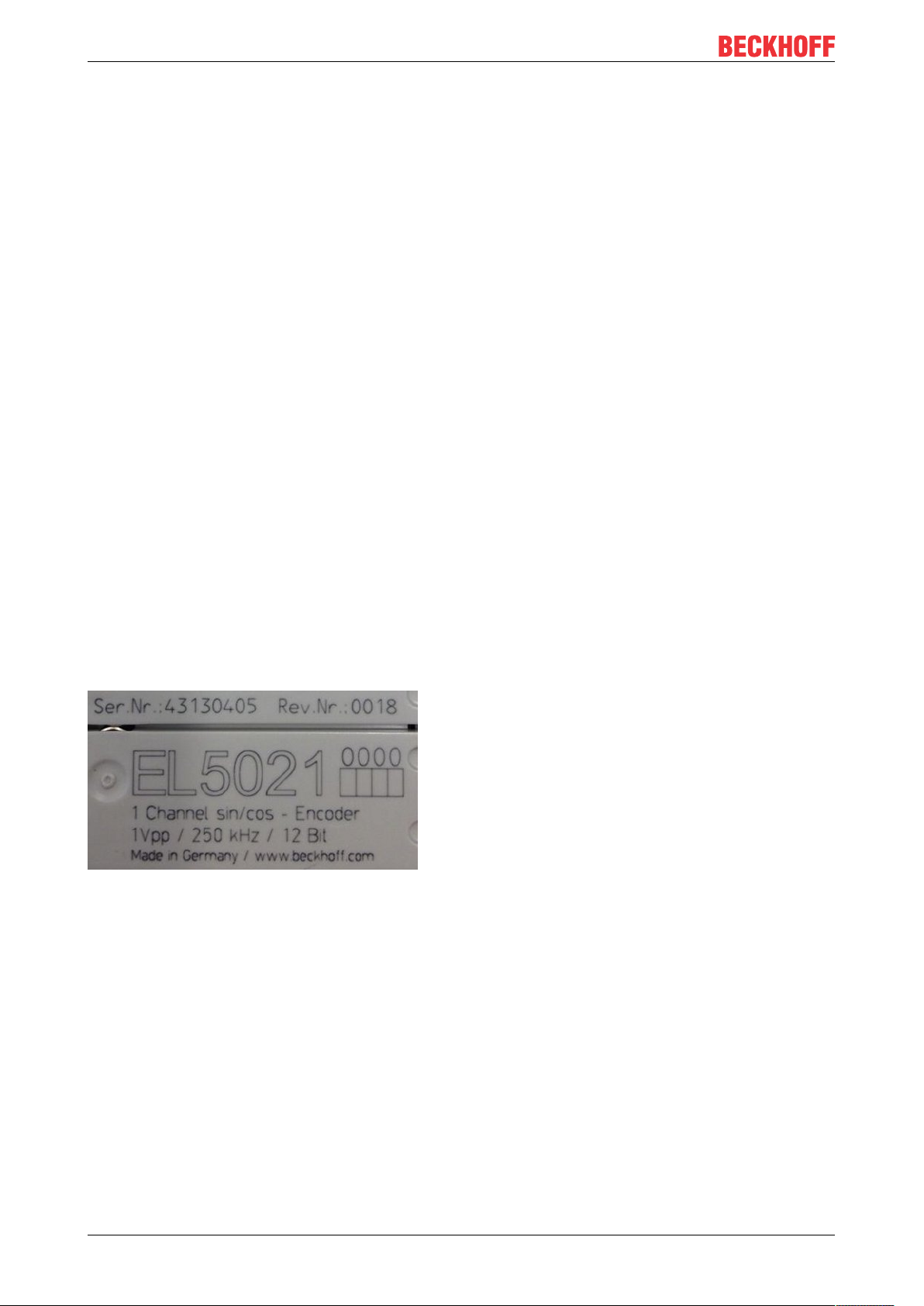
Examples of markings
Fig.1: EL5021 EL terminal, standard IP20 IO device with serial/ batch number and revision ID (since
2014/01)
EL20448 Version: 1.0
Page 9
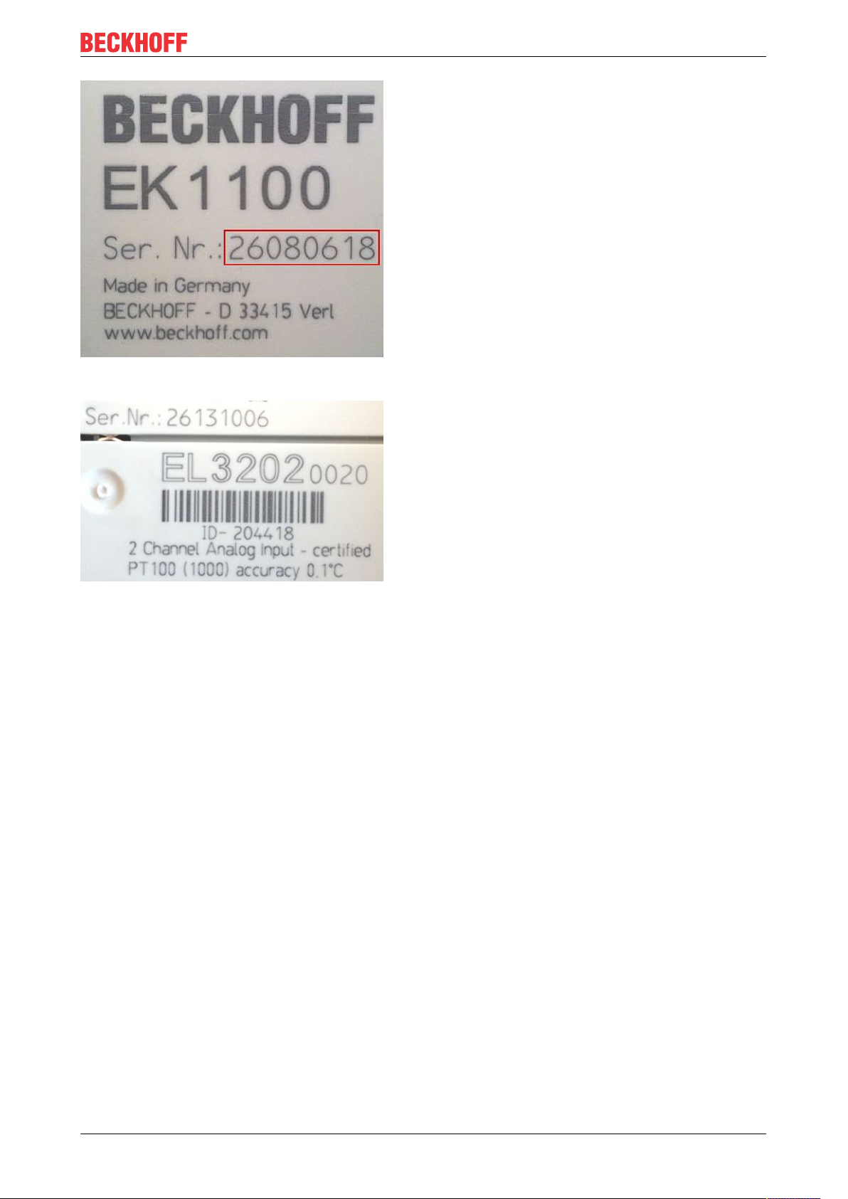
Fig.2: EK1100 EtherCAT coupler, standard IP20 IO device with serial/ batch number
Foreword
Fig.3: EL3202-0020 with serial/ batch number 26131006 and unique ID-number 204418
EL2044 9Version: 1.0
Page 10
Foreword
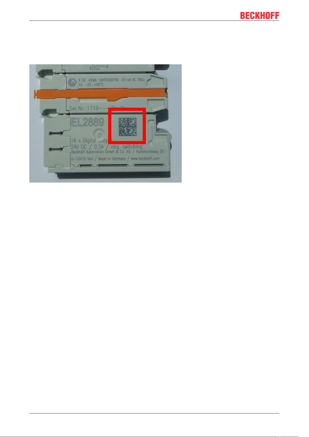
1.4.1 Beckhoff Identification Code (BIC)
The Beckhoff Identification Code (BIC) is increasingly being applied to Beckhoff products to uniquely identify
the product. The BIC is represented as a Data Matrix Code (DMC, code scheme ECC200), the content is
based on the ANSI standard MH10.8.2-2016.
Fig.4: BIC as data matrix code (DMC, code scheme ECC200)
The BIC will be introduced step by step across all product groups.
Depending on the product, it can be found in the following places:
• on the packaging unit
• directly on the product (if space suffices)
• on the packaging unit and the product
The BIC is machine-readable and contains information that can also be used by the customer for handling
and product management.
Each piece of information can be uniquely identified using the so-called data identifier
(ANSIMH10.8.2-2016). The data identifier is followed by a character string. Both together have a maximum
length according to the table below. If the information is shorter, spaces are added to it. The data under
positions 1 to 4 are always available.
The following information is contained:
EL204410 Version: 1.0
Page 11

Item
Type of
no.
information
1 Beckhoff order
number
2 Beckhoff Traceability
Number (BTN)
3 Article description Beckhoff article
4 Quantity Quantity in packaging
5 Batch number Optional: Year and week
6 ID/serial number Optional: Present-day
7 Variant number Optional: Product variant
...
Explanation Data
Beckhoff order number 1P 8 1P072222
Unique serial number,
see note below
description, e.g.
EL1008
unit, e.g. 1, 10, etc.
of production
serial number system,
e.g. with safety products
number on the basis of
standard products
Foreword
Number of digits
identifier
S 12 SBTNk4p562d7
1K 32 1KEL1809
Q 6 Q1
2P 14 2P401503180016
51S 12 51S678294104
30P 32 30PF971, 2*K183
incl. data identifier
Example
Further types of information and data identifiers are used by Beckhoff and serve internal processes.
Structure of the BIC
Example of composite information from item 1 to 4 and 6. The data identifiers are marked in red for better
display:
BTN
An important component of the BIC is the Beckhoff Traceability Number (BTN, item no.2). The BTN is a
unique serial number consisting of eight characters that will replace all other serial number systems at
Beckhoff in the long term (e.g. batch designations on IO components, previous serial number range for
safety products, etc.). The BTN will also be introduced step by step, so it may happen that the BTN is not yet
coded in the BIC.
NOTE
This information has been carefully prepared. However, the procedure described is constantly being further
developed. We reserve the right to revise and change procedures and documentation at any time and without prior notice. No claims for changes can be made from the information, illustrations and descriptions in
this information.
EL2044 11Version: 1.0
Page 12
Product overview
2 Product overview
2.1 Introduction
Fig.5: EL2044
Four-channel digital output terminal, 24VDC, 2A, with extended diagnostics
The EL2044 digital output terminal connects the binary control signals from the automation device on to the
actuators at the process level with electrical isolation.
The EL2044 is protected against polarity reversal and processes load currents with outputs protected against
overload and short-circuit. The integrated diagnostics can be evaluated in the controller and is indicated by
the LEDs. Overtemperature and the lack of a voltage supply to the terminal are supplied as diagnostic
information. Beyond that each channel can among other things signal a short circuit individually.
Maintenance of the application is simplified by the diagnostics.
The power contacts are connected through. The outputs are fed via the 24V power contact in the EL2044.
NOTE
Watchdog settings
Please refer to section "Notes for setting the watchdog [}33]"!
EL204412 Version: 1.0
Page 13

Product overview
2.2 Technical data
Technical data EL2044
Connection technology 2-wire
Number of outputs 4
Nominal voltage 24VDC (-15%/ +20%)
Load type ohmic, inductive, lamp load up to 24W max.
Max. output current 2A (short-circuit proof) per channel, with diagnostics
Output stage push (high-side switch)
Short circuit current < 4Atyp.
Reverse polarity protection yes
Switching times TON: 50µs typ., T
Power supply for the electronics via the power contacts
Breaking energy < 150mJ/channel typ.
Current consumption via E-bus typ. 55mA
Recommended cycle time ≥ 200µs;
with cycle times < 200µs the process data is not updated in each
cycle.
Electrical isolation 500V (E-bus/field voltage)
Current consumption power contacts typ. 25mA + load
Supports NoCoeStorage [}38] function
Configuration via System Manager
Conductor types solid wire, stranded wire and ferrule
Special features diagnostics via process data and LED: overtemperature,
Weight approx. 50g
Permissible ambient temperature range
during operation
Permissible ambient temperature range
during storage
Permissible relative air humidity 95%, no condensation
Dimensions (W x H x D) approx. 15mm x 100mm x 70mm (width aligned: 12mm)
Mounting on 35mm mounting rail according to EN60715
Vibration/shock resistance conforms to EN 60068-2-6 / EN 60068-2-27,
EMC immunity/emission conforms to EN61000-6-2 / EN61000-6-4
Protection class IP20
Installation position variable
Approval CE
yes
PowerFail, short circuit (per channel), open load detection
0 °C ... +55 °C
-25 °C ... +85 °C
: 100µs typ.
OFF
EL2044 13Version: 1.0
Page 14
Product overview
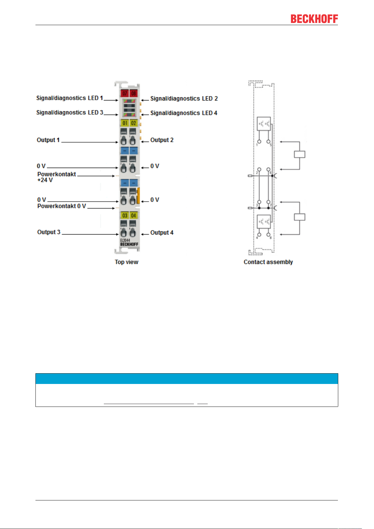
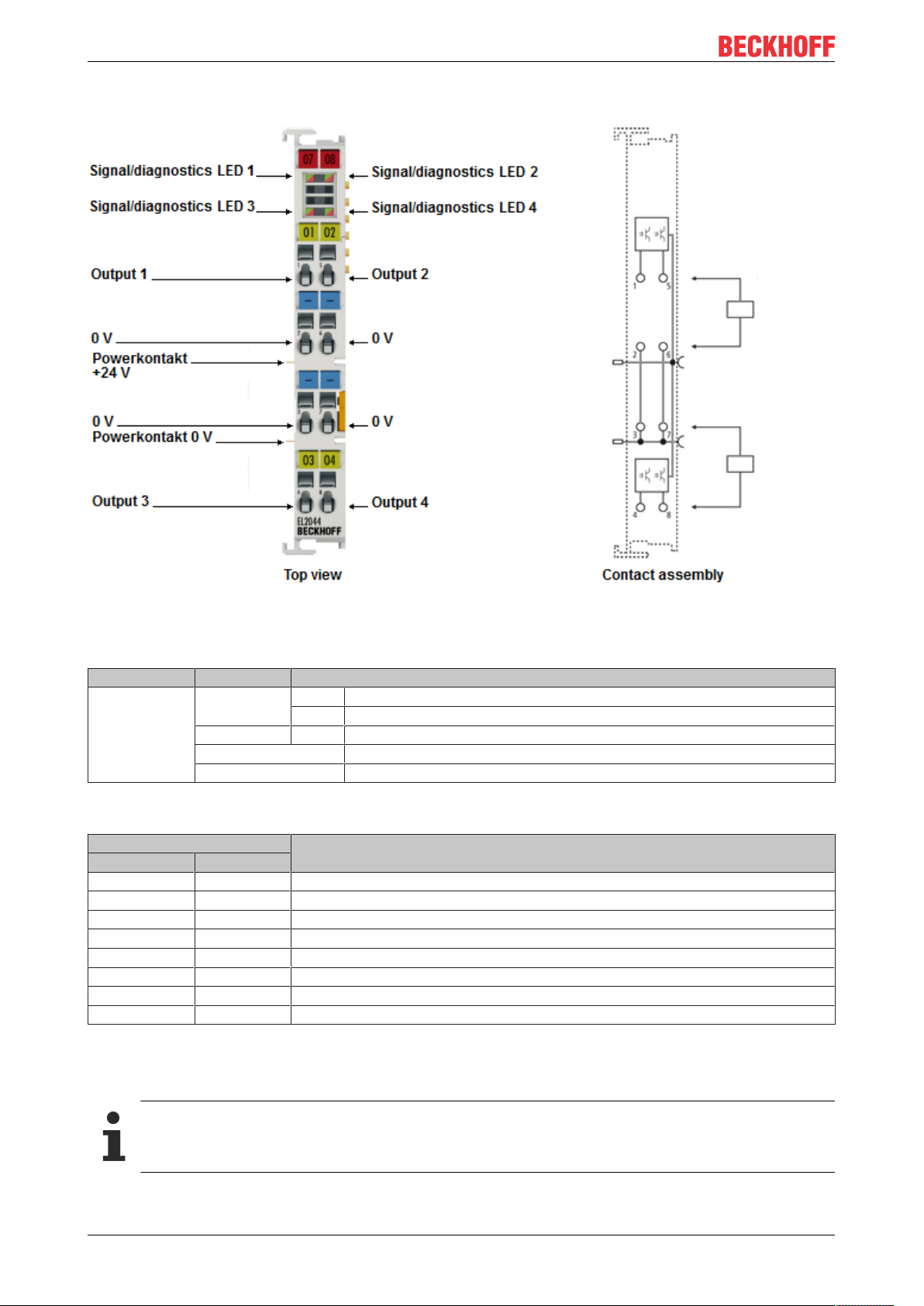
2.3 Pin assignment and LEDs
Fig.6: EL2044
EL2044 - LEDs
LED Color Meaning
OUTPUT 1- 4 green off No output signal
on Output signal 24V
red on ERROR: Overcurrent / Overtemperature
flashing red ERROR: Short circuit to 24V
red / green alternating ERROR: Open Load
EL2044 - Connection
Terminal point Description
Name No.
Output1 1 Output 1
0V 2 Ground for output1 (internally connected to terminal point3, 6, 7 and negative power contact)
0V 3 Ground for output3 (internally connected to terminal point2, 6, 7 and negative power contact)
Output3 4 Output 3
Output2 5 Output 2
0V 6 Ground for output2 (internally connected to terminal point2, 3, 7 and negative power contact)
0V 7 Ground for output4 (internally connected to terminal point2, 3, 6 and negative power contact)
Output4 8 Output 4
2.4 Overload protection
Technical data
Please note the information in the technical data regarding load type, max. output current and short
circuit current.
EL204414 Version: 1.0
Page 15
Product overview
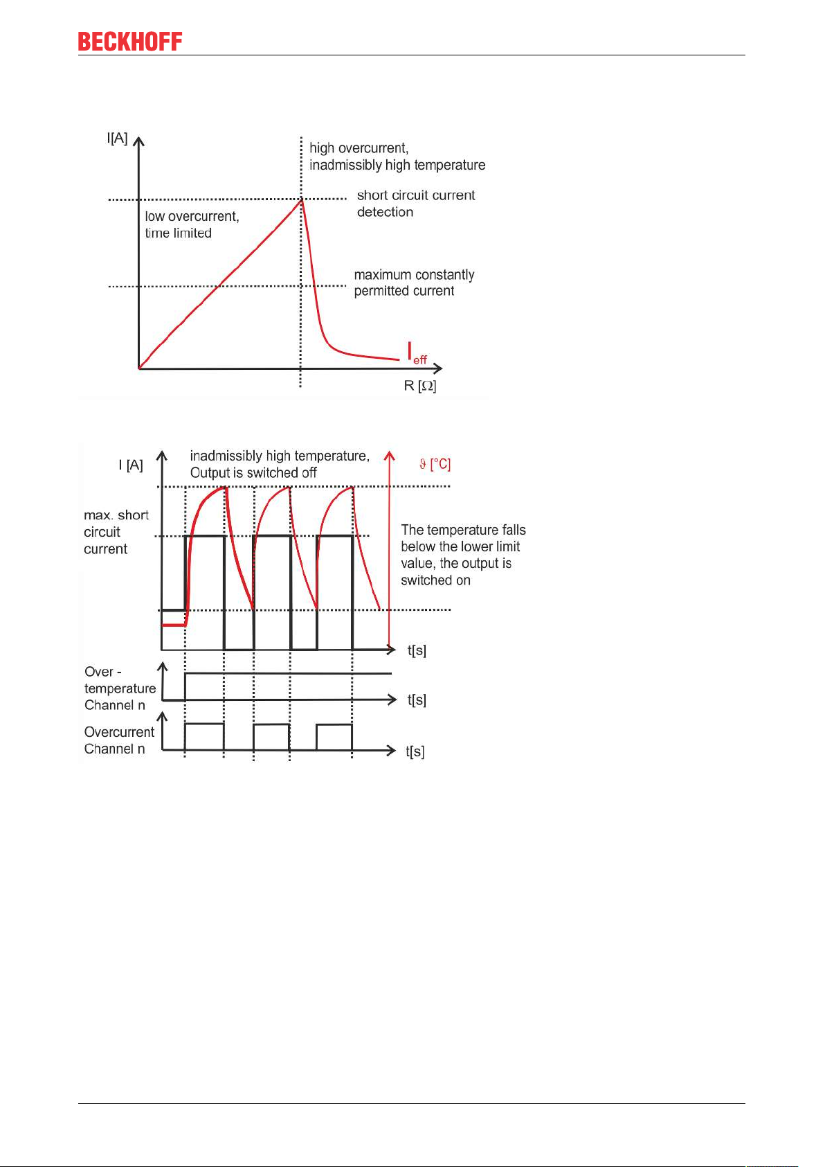
When switching on lamp loads, high starting currents occur that are limited by the output circuit of the
terminals (see fig. Overload current limitation).
Fig.7: Overload current limitation
Fig.8: Schematic illustration of the thermal switch-off in case of overload
In case of a long-term overload and/or short-circuit, the output is protected by the thermal switch-off of the
channel.
The output circuit of the terminal limits the current. The terminal maintains this current until important selfheating of the channel occurs.
On exceeding the upper temperature limit, the terminal switches the channel off.
The channel is switched on again after it has cooled down to below the lower temperature limit.
The output signal is clocked until the output is switched off by the controller or the short-circuit is eliminated
(see fig. Schematic illustration of the thermal switch-off in case of overload). The clock frequency depends
on the ambient temperature and the load of the other terminal channels.
Short-circuit or prolonged overload on a channel leads to an increase in the device temperature. If several
channels are overloaded, this leads to a rapid increase in the device temperature. The overloaded channels
are switched off when the upper limit for the device temperature is exceeded. The channels are only
switched on again if the temperature falls below the lower limit values for both the device and the channel.
The non-overloaded channels continue operating properly.
EL2044 15Version: 1.0
Page 16
Product overview
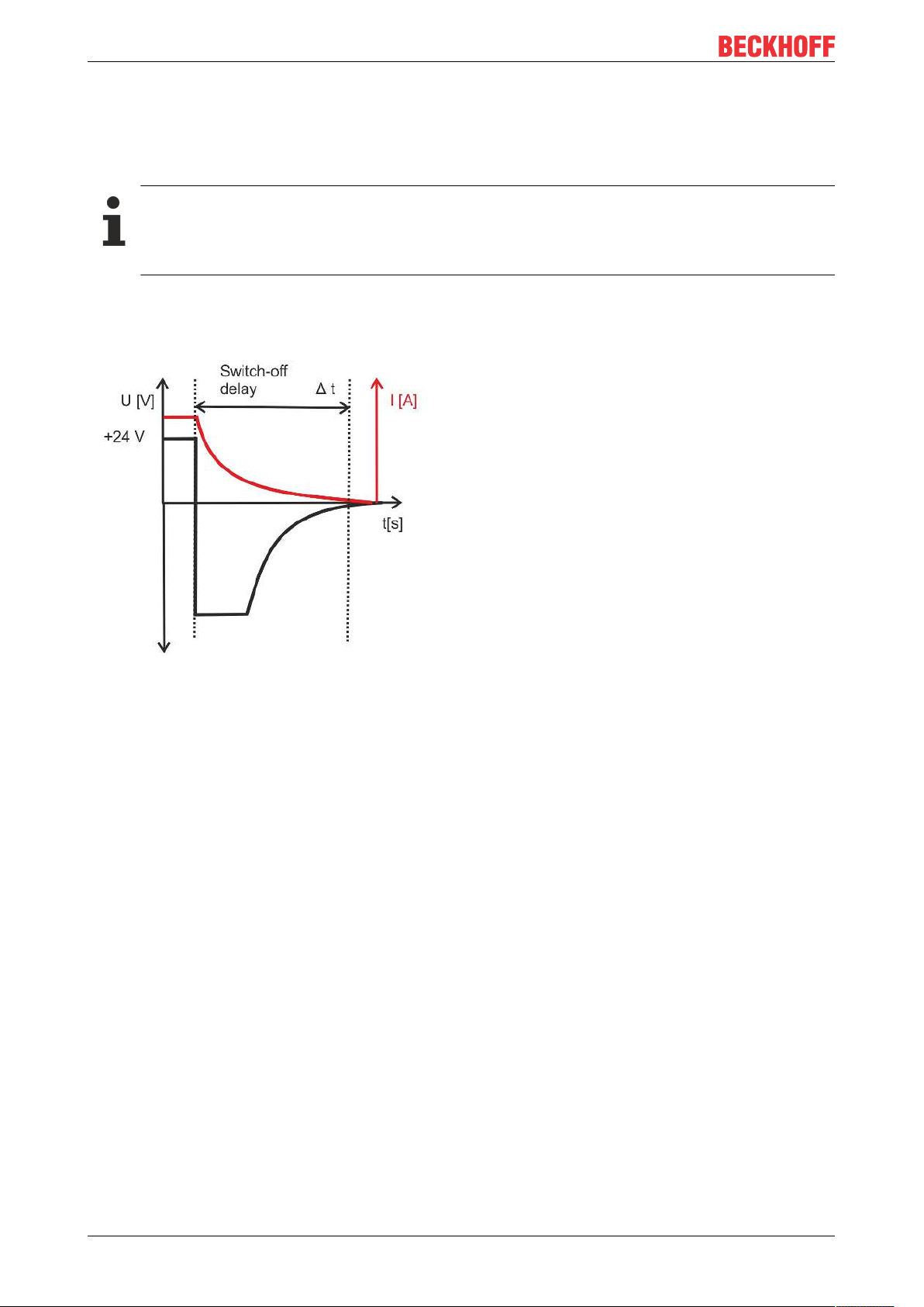
When switching off inductive loads, high induction voltages result from interrupting the current too quickly.
These are limited by an integrated free-wheeling diode (switch-off energy [inductive] see Technical data).
Since the current reduces only slowly, a delayed switch-off can occur in many control applications. For
example, a valve remains open for many milliseconds. Switch-off times are realized that correspond, for
instance, to the switch-on time of the coil.
Protection against high induction voltages
To protect against voltage peaks such as can occur when switching inductive loads, we recommend
to provide suitable protective circuits (e.g. with the free-wheeling diode, RC combination or varistor)
directly at the actuator.
Fig.9: Switch-off of inductive loads
EL204416 Version: 1.0
Page 17
Product overview
2.5 Operating modes and settings
2.5.1 Process data
Parameterization
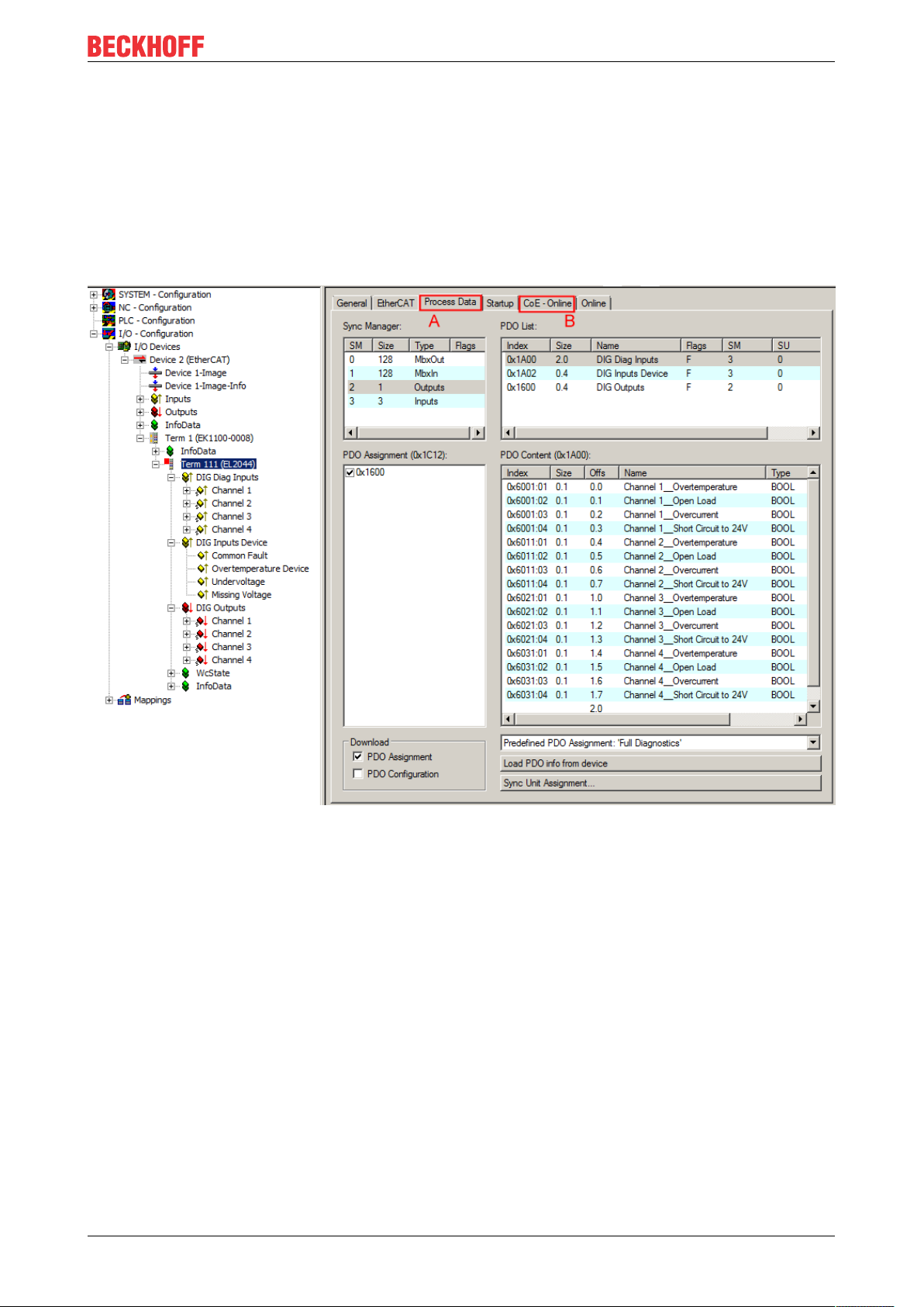
An EL2044 is parameterized via 2 tabs in the TwinCAT System Manager: the Process Data tab (A) for the
communication-specific settings and the CoE directory (B) for the settings in the slave.
Fig.10: EL2044 - "Process data" tab
• Changes to the process data-specific settings are generally only effective after a restart of the
EtherCAT master:
restart TwinCAT in RUN or CONFIG mode; RELOAD in CONFIG mode
• Changes to the online CoE directory
◦ are in general immediately effective
◦ are generally stored in non-volatile memory in the terminal/slave. They should be entered in the
CoE StartUp list so that the settings are accepted after a replacement of the terminal. The CoE
StartUp list is processed at each EtherCAT start and the settings are loaded into the slave.
Illustration of the process data and structural contents
The EL2044 provides three different process data for transmission:
• the diagnostics per channel "DIG Diag Inputs",
• device diagnostics "DIG Inputs Device",
• switching state of the outputs "DIG Outputs"
EL2044 17Version: 1.0
Page 18
Product overview
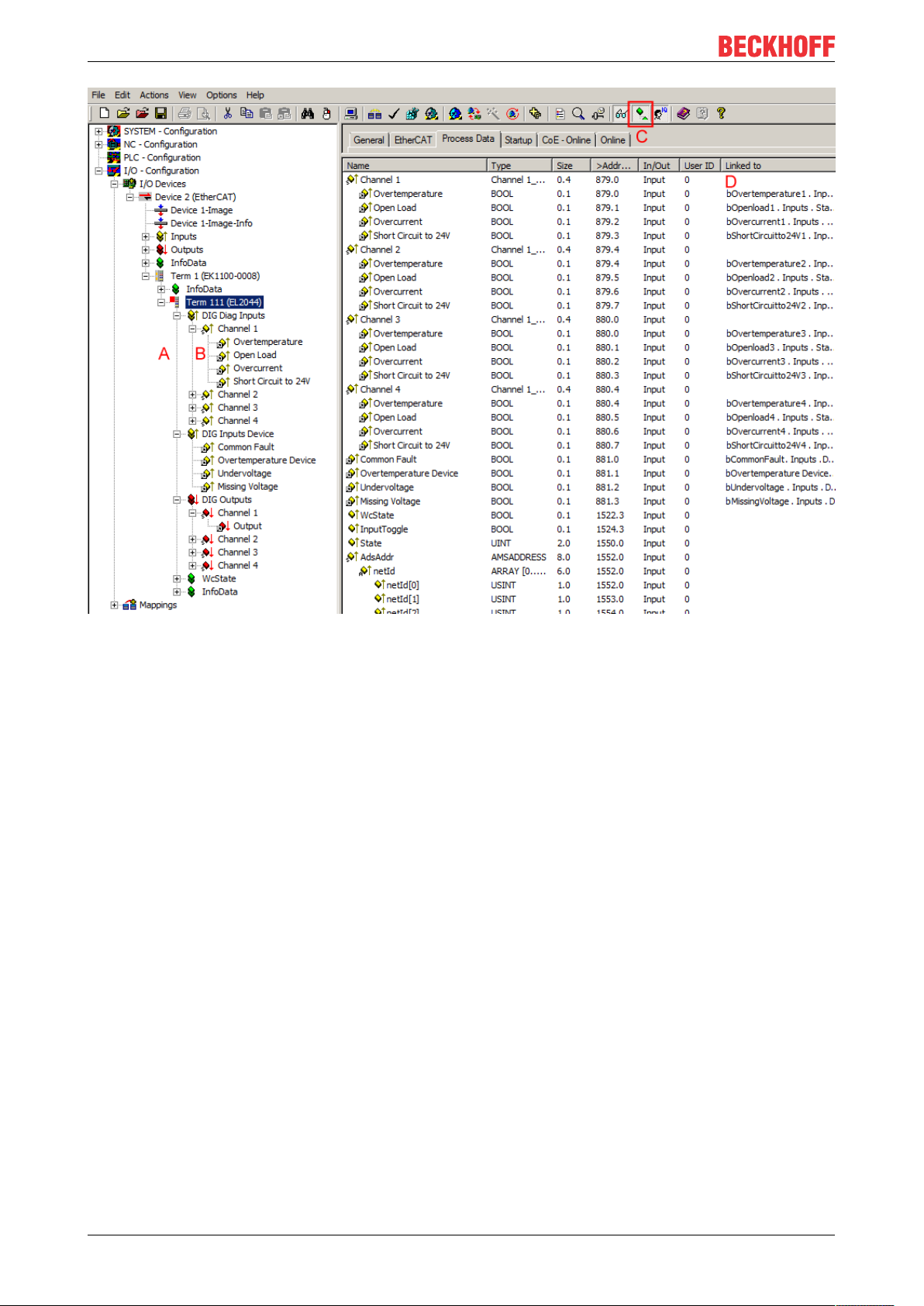
Fig.11: EL2044 Online illustration of the process data and structural contents in the System Manager
The plain text display of the bit meanings is particularly helpful not only in commissioning but also for linking
to the PLC program.
By right-clicking on the status variable in the configuration tree (A), the structure can be opened for linking
(B).
Activation of the "Show Sub Variables" button (C) displays all subvariables and links to the PLC (D) in the
online view.
"Predefined PDO Assignment" selection dialog (from TwinCAT 2.11 build 1544 onwards)
The process data to be transmitted (PDO, ProcessDataObjects) can be selected by the user
• for all TwinCAT versions via the "Predefined PDO Assignment" selection dialog (see fig. "EL2044
Process Data tab" A) or
• selectively for individual PDOs (see fig. "EL2044 Process Data tab" B)
These changes become effective after activation and an EtherCAT restart or a reload.
EL204418 Version: 1.0
Page 19
Product overview
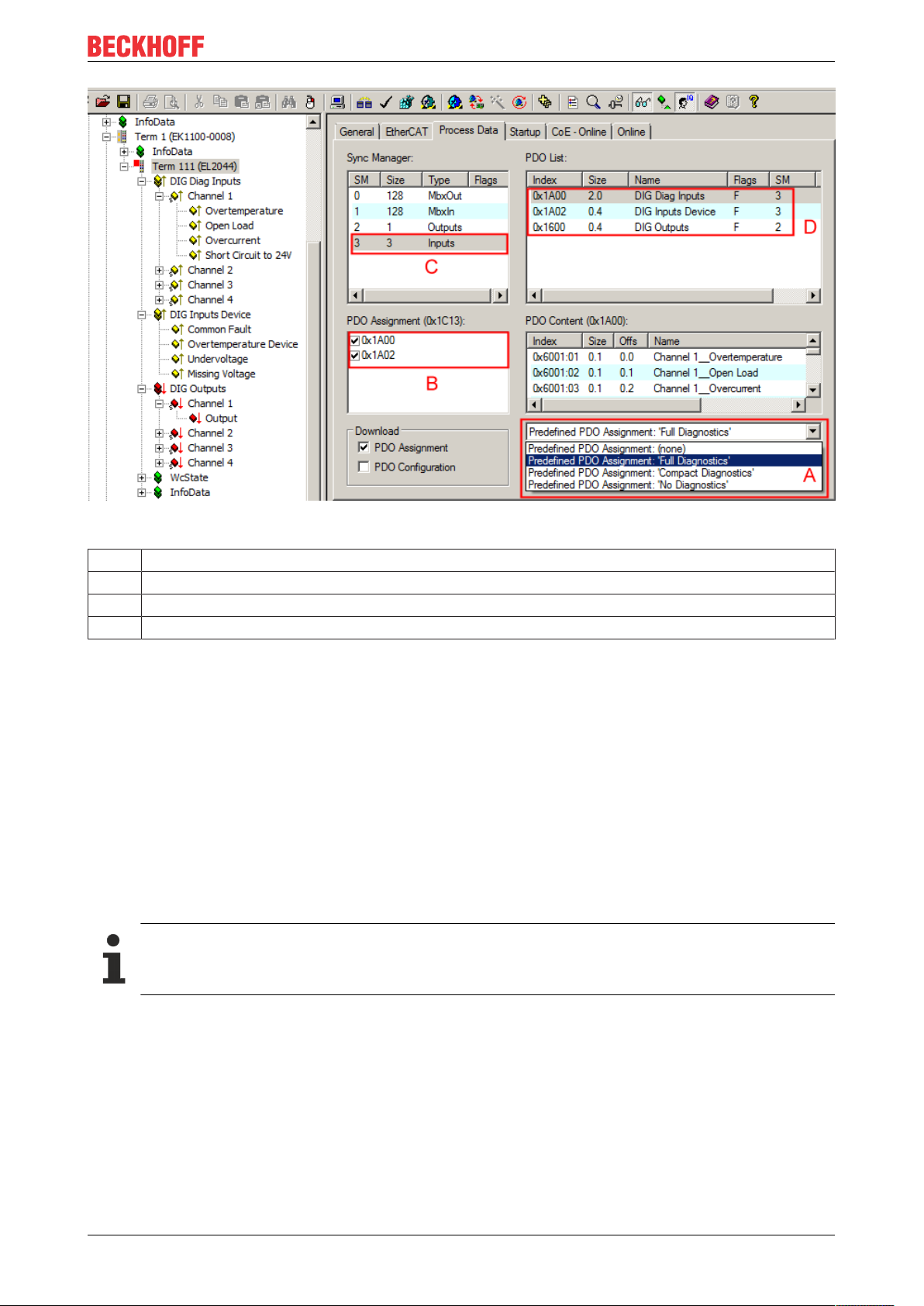
Fig.12: EL2044 "Process data" tab
A Selection of the diagnostic scope via the selection dialog "Predefined PDO Assignment"
B Display of (optional) PDOs (process data objects)
C Selection of the required Sync Manager
D Display of the PDOs available for selection
Three pre-defined PDO assignments can be selected:
• Full Diagnostics:
Inputs: Selection of the PDOs 0x1A00 (diagnostics per channel) and 0x1A02 (device diagnostics). Both
the diagnostic data for each channel and the data for the device diagnostics are displayed and
transmitted.
Outputs: PDO 0x1600 (switching state of the outputs) is displayed and transmitted.
• Compact Diagnostics:
Inputs: Selection of the PDO 0x1A02 (device diagnostics). Only the diagnostic data for the device are
displayed in the System Manager and transmitted to the control system.
Outputs: PDO 0x1600 (switching state of the outputs) is displayed and transmitted.
• No Diagnostics: Neither 0x1A00 nor 0x1A02 is selected. No diagnostic data are displayed in the
System Manager and none are transmitted to the control system.
Outputs: PDO 0x1600 (switching state of the outputs) is displayed and transmitted.
Compact Diagnostics, No Diagnostics
When converting from "Full Diagnostics" to "Compact Diagnostics" or "No Diagnostics", or when deactivating the PDO 0x1600, links already established to the deactivated objects are deleted.
EL2044 19Version: 1.0
Page 20

Product overview
2.5.2 Diagnostics per channel
Open Load (Index 0x60n1:02 [}25])
The open load detection shows that no load is connected when the output is switched on.
The "Open Load" bit (index 0x60n1:02) is set to TRUE if the output is TRUE and the output current is less
than typ. 0.8mA.
Short Circuit to 24V (Index 0x60n1:04)
A short circuit to 24 V is detected if the output is FALSE, but nevertheless a voltage of more than typ. 10 V is
present. The “Short Circuit to 24V” bit (index 0x60n1:04) is set to TRUE. The corresponding LED flashes red.
Overtemperature (index: 0x60n1:01) – overcurrent (index:0x60n1:03)
The “Overcurrent” bit (index: 0x60n1:03) is set in case of an overload. The LED lights up red. The channel
heats up, so that the “Overtemperature” bit (index: 0x60n1:01) is set on reaching an upper limit temperature
(see fig. Overload current limitation [}16]).
In the case of a short-circuit the channel overheats very quickly, leading to it being switched off. Once the
temperature has cooled down to below a lower limit value following the switch-off, the output is switched on
again. The temperature, however, is then still so high that the “Overtemperature” bit (index: 0x60n1:01)
remains set. Thus the LED remains red as long as the short-circuit is present.
Overcurrent diagnostics is no longer possible once the output is switched off. The “Overcurrent” bit (index:
0x60n1:03) is only set to TRUE when the output is switched on again (see fig. Schematic illustration of the
thermal switch-off in case of overload [}16]).
2.5.3 Device diagnostics
General error (index 0xF600:11)
If the “Common Fault” bit (index 0xF600:11) is set, there is an error on one or more channels.
It is thus possible in the “Compact Diagnostics” process mode to determine that errors have occurred on one
or more channels.
Device overtemperature (index 0xF600:12)
The device temperature rises due to an overload, a short-circuit or excessively high ambient temperature. If
the device temperature exceeds the upper limit value, the overloaded channels are switched off. The
“Overtemperature Device” bit (index 0xF600:12) is set. All other channels continue to operate properly.
If the device temperature falls below the lower limit value the “Overtemperature Device” bit (index
0xF600:12) is reset. If the channel temperature also falls below the lower limit value, the respective channels
are switched on again.
Undervoltage (index 0xF600:13)
If the “Undervoltage” bit (index 0xF600:13) is set, the supply voltage of the terminal has fallen below typically
17 V.
Voltage loss (index 0xF600:14)
If the error bit in “Missing Voltage” (index 0xF600:14) is set, the supply voltage of the terminal has fallen
below typically 14 V.
EL204420 Version: 1.0
Page 21
2.5.4 Settings via the CoE directory
CoE online directory
Product overview
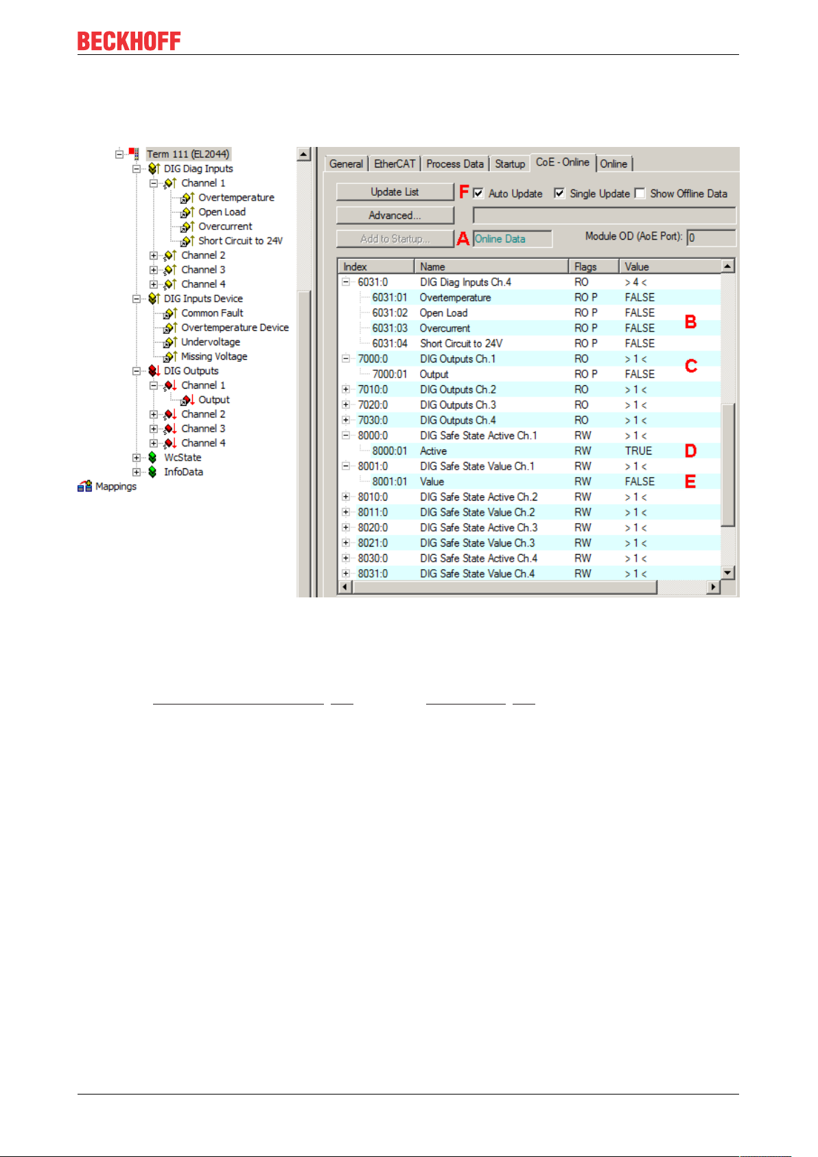
Fig.13: EL2044 - CoE - Directory
The online data are accessible (A) if the terminal is online, i.e. connected to the EtherCAT Master TwinCAT
and in an error-free RUN state (WorkingCounter = 0). The entries "DIG Safe State Active Ch.n" (index
0x80n0) (D) and "DIG Safe State Value Ch.n" (index 0x80n1) (E) can be changed online; please also
observe the Notes on the CoE interface [}37] and on the StartUp-List [}38].
The diagnostic data of the channels can be read under "DIG Diag Inputs Ch.n" (index 0x60n1) (B).
The diagnostic data of the terminal can be read under "DIG Inputs Device" (index 0xF600).
The state of the outputs can be read under "DIG Outputs Ch.n" (index 0x70n0) (C).
The display in TwinCAT is continuously updated if (F) has been activated.
EL2044 21Version: 1.0
Page 22
Product overview
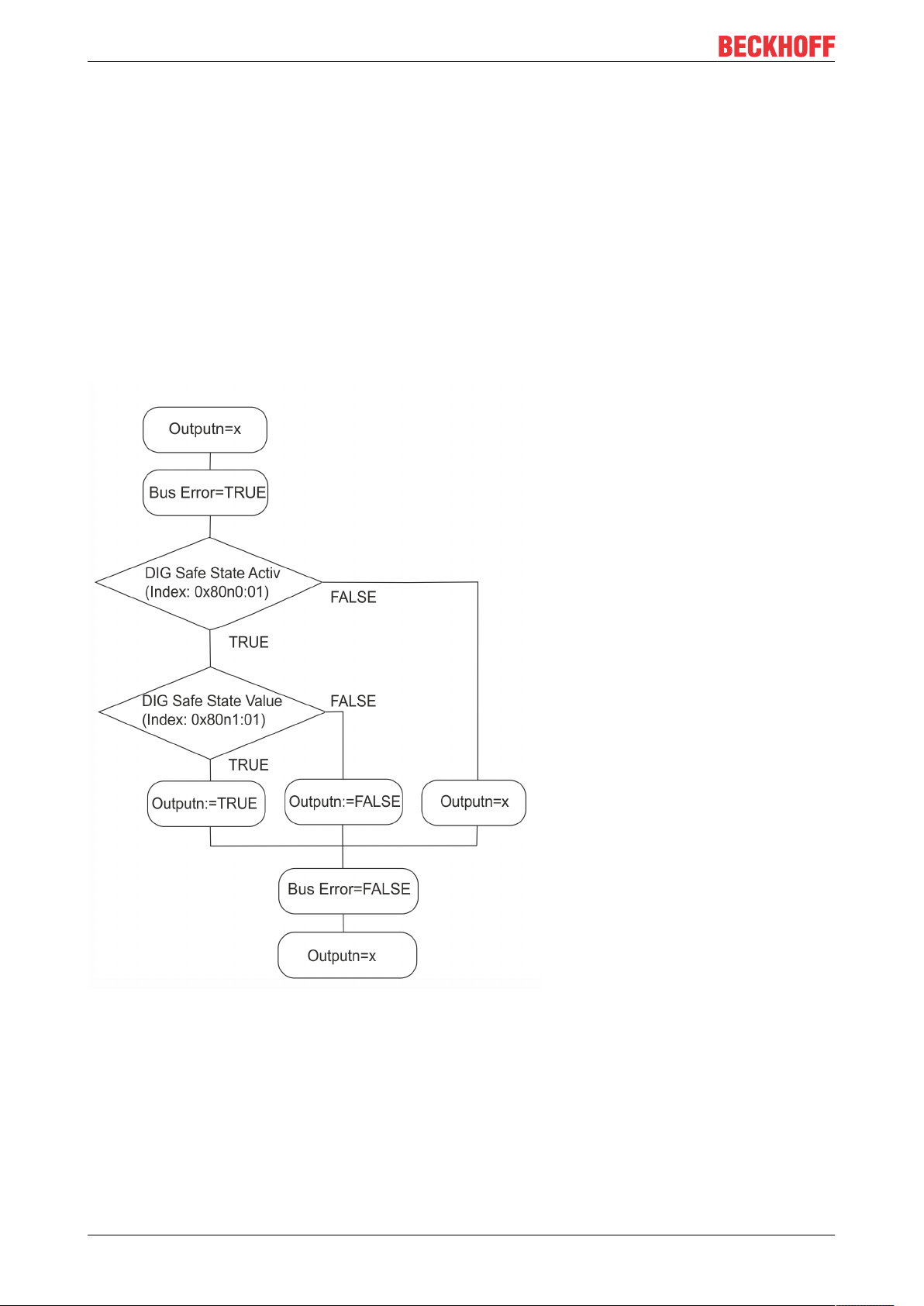
DIG Safe State Active (index 0x80n0:01) / DIG Safe State Value (index 0x80n1:01)
The setting in “DIG Safe State Active” (index 0x80n0:01) defines whether the outputs should assume a safe
state in the case of a bus error. The safe state of the output in the case of a bus error is defined with “DIG
Safe State Value” (index 0x80n1:01).
1. “DIG Safe State Active“ = TRUE and
◦ “DIG Safe State Value“ = TRUE: the output is switched on.
2. “DIG Safe State Active“ = TRUE and
◦ “DIG Safe State Value“ = FALSE: the output is switched off
3. “DIG Safe State Active“ = FALSE
◦ The state of the output is retained. Entries in “DIG Safe State Value” (index 0x80n1:01) have no
effect.
Flow-chart illustration of the sequence in case of a bus error
Fig.14: Change of state of the outputs in the case of a bus error
EL204422 Version: 1.0
Page 23
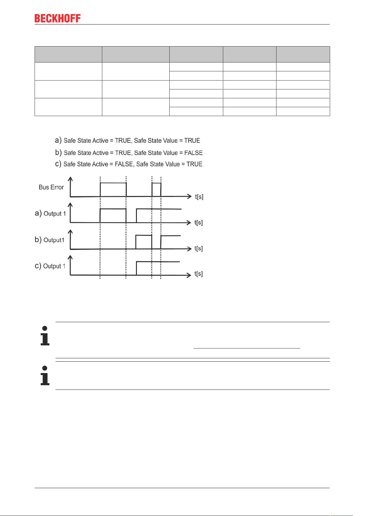
Tabular example:
Product overview
DIG Safe State Active
Index 0x80n0:01
TRUE TRUE FALSE TRUE FALSE
TRUE FALSE FALSE FALSE FALSE
FALSE FALSE / TRUE FALSE FALSE FALSE
Graphical example:
DIG Safe State Value
Index 0x80n1:01
Output before
bus error
TRUE TRUE TRUE
TRUE FALSE TRUE
TRUE TRUE TRUE
Output during
bus error
Output after bus
error
Fig.15: Graphical illustration of the channel state during a bus error
2.6 Object description and parameterization
EtherCAT XML Device Description
The display matches that of the CoE objects from the EtherCAT XML Device Description. We recommend downloading the latest XML file from the download area of the Beckhoff website and in-
stalling it according to installation instructions.
Parameterization
The terminal is parameterized via the CoE Online tab (double-click on the respective object), or the
PDOs are allocated via the Process Data tab.
Introduction
The CoE overview contains objects for different intended applications:
EL2044 23Version: 1.0
Page 24

Product overview
2.6.1 Restore object
Index 1011 Restore default parameters
Index (hex) Name Meaning Data type Flags Default value
1011:0
1011:01 SubIndex 001 If this object is set to "0x64616F6C" in the set value
Restore default parameters [}134]
Restore default parameters UINT8 RO 0x01 (1
dialog, all backup objects are reset to their delivery
state.
UINT32 RW 0x00000000
(0
)
dec
)
dec
2.6.2 Configuration data
Index 80n0 DIG Safe State Active Ch.n
(n=0 for Ch.1 to n=3 for Ch.4)
Index
(hex)
80n0:0 DIG Safe State Active
80n0:01 Active Enabling of the output state defined in index 0x80n1:01
Name Meaning Data type Flags Default
Maximum subindex UINT8 RO 0x01 (1
Ch.n
BOOLEAN RW 0x01 (1
in case of a bus error
0: output retains its current state.
1: output is switched to the state defined in index 0x80n1.
)
dec
)
dec
Index 80n1 DIG Safe State Value Ch.n
(n=0 for Ch.1 to n=3 for Ch.4)
Index
(hex)
80n1:0 DIG Safe State Value
80n1:01 Value Defines the state of the output in case of a bus error:
Name Meaning Data type Flags Default
Maximum subindex UINT8 RO 0x01 (1
Ch.n
BOOLEAN RW 0x00 (0
0: output off
1: output on
)
dec
)
dec
2.6.3 Command object
Index FB00 DIG Command
Index (hex) Name Meaning Data type Flags Default value
FB00:0 DIG Command Maximum subindex UINT8 RO 0x03 (3
FB00:01 Request reserved OCTET -
STRING[2]
FB00:02 Status reserved UINT8 RO 0x00 (0
FB00:03 Response reserved OCTET -
STRING[4]
RW {0}
RO {0}
)
dec
)
dec
EL204424 Version: 1.0
Page 25

Product overview
2.6.4 Input data
Index 60n1 DIG Diag Inputs
(n=0 for Ch.1 to n=3 for Ch.4)
Index (hex) Name Meaning Data type Flags Default
60n1:0 DIG Diag Inputs Ch.n Maximum subindex UINT8 RO 0x04 (4
60n1:01
Overtemperature
[}20]
60n1:02 Open Load Wire break detection
60n1:03
60n1:04
Overcurrent [}20]
Short Circuit to 24V
[}20]
Index F600 DIG Inputs Device
The "overtemperature" bit is set if the max. permissible
temperature of the channel is exceeded.
The Open Load bit is set if the channel is switched on
and the load current is ≤ typically 0.8mA.
Overcurrent and short-circuit detection
The "overcurrent" bit is set if an overload is detected
when the channel is switched on.
No overload can be detected if the channel is switched
off (e.g. thermal switch-off).
Short-circuit current detection: typ.<4A
The Short Circuit to 24V bit is set if voltage is present
when the channel is switched off.
BOOLEAN RO 0x00 (0
BOOLEAN RO 0x00 (0
BOOLEAN RO 0x00 (0
BOOLEAN RO 0x00 (0
)
dec
)
dec
)
dec
)
dec
)
dec
Index (hex) Name Meaning Data type Flags Default
F600:0 DIG Inputs Device Maximum subindex UINT8 RO 0x14 (20
F600:11
F600:12
Common Fault [}20]
Overtemperature Device [}20]
The Common Fault bit is set if an error occurs on one
or more channels of the terminal.
The Overtemperature Device bit is set if the max. permissible device temperature is exceeded.
The overloaded channels are switched off until the de-
BOOLEAN RO 0x00 (0
BOOLEAN RO 0x00 (0
vice temperature cools down below the lower limit
value again.
F600:13
F600:14
Undervoltage [}20]
Missing Voltage [}20]
The Undervoltage bit is set if the terminal supply voltage falls below typically 17V.
The Missing Voltage bit is set if the supply voltage is
lower than typically 14V.
BOOLEAN RO 0x00 (0
BOOLEAN RO 0x00 (0
2.6.5 Output data
Index 70n0 DIG Outputs
(n=0 for Ch.1 to n=3 for Ch.4)
Index (hex) Name Meaning Data type Flags Default
70n0:0 DIG Outputs Ch.n Maximum subindex UINT8 RO 0x01 (1
70n0:01 Output Status Output
0: Output off
1: Output on
BOOLEAN RO 0x00 (0
)
dec
)
dec
)
dec
)
dec
)
dec
)
dec
)
dec
2.6.6 Standard objects (0x1000 - 0x1FFF)
Index 1000 Device type
Index (hex) Name Meaning Data type Flags Default value
1000:0 Device type Device type of the EtherCAT slave: the Lo-Word con-
tains the CoE profile used (5001). The Hi-Word contains the module profile according to the modular device profile.
EL2044 25Version: 1.0
UINT32 RO 0x01181389
(18355081
dec
)
Page 26

Product overview
Index 1008 Device name
Index (hex) Name Meaning Data type Flags Default
1008:0 Device name Device name of the EtherCAT slave STRING RO EL2044
Index 1009 Hardware version
Index (hex) Name Meaning Data type Flags Default value
1009:0 Hardware version Hardware version of the EtherCAT slave STRING RO
Index 100A Software version
Index (hex) Name Meaning Data type Flags Default value
100A:0 Software version Firmware version of the EtherCAT slave STRING RO 01
Index 1018 Identity
Index (hex) Name Meaning Data type Flags Default
1018:0 Identity Information for identifying the slave UINT8 RO 0x04 (4
1018:01 Vendor ID Vendor ID of the EtherCAT slave UINT32 RO 0x00000002
(2
1018:02 Product code Product code of the EtherCAT slave UINT32 RO 0x07FC3052
(133967954
1018:03 Revision Revision numberof the EtherCAT slave; the Low Word
(bit 0-15) indicates the special terminal number, the
UINT32 RO 0x00000000
(0
High Word (bit 16-31) refers to the device description
1018:04 Serial number Serial number of the EtherCAT slave; the Low Byte (bit
0-7) of the Low Word contains the year of production,
UINT32 RO 0x00000000
(0
the High Byte (bit 8-15) of the Low Word contains the
week of production, the High Word (bit 16-31) is 0
)
dec
)
dec
)
dec
)
dec
)
dec
Index 10F0 Backup parameter handling
Index (hex) Name Meaning Data type Flags Default value
10F0:0 Backup parameter
handling
10F0:01 Checksum Checksum across all backup entries of the EtherCAT
Information for standardized loading and saving of
backup entries
slave
UINT8 RO 0x01 (1
)
dec
UINT32 RO 0x00000000
(0
)
dec
Index 1600 DIG RxPDO-Map Outputs
Index (hex) Name Meaning Data type Flags Default
1600:0 DIG RxPDO-Map Out-
puts
1600:01 SubIndex 001 1. PDO Mapping entry (object 0x7000 (DIG Outputs
1600:02 SubIndex 002 2. PDO Mapping entry (object 0x7010 (DIG Outputs
1600:03 SubIndex 003 3. PDO Mapping entry (object 0x7020 (DIG Outputs
1600:04 SubIndex 004 4. PDO Mapping entry (object 0x7030 (DIG Outputs
PDO Mapping RxPDO 1 UINT8 RO 0x04 (4
UINT32 RO 0x7000:01, 1
Ch.1), entry 0x01 (Output))
UINT32 RO 0x7010:01, 1
Ch.2), entry 0x01 (Output))
UINT32 RO 0x7020:01, 1
Ch.3), entry 0x01 (Output))
UINT32 RO 0x7030:01, 1
Ch.4), entry 0x01 (Output))
)
dec
EL204426 Version: 1.0
Page 27

Product overview
Index 1A00 DIG TxPDO-Map Diag Inputs
Index (hex) Name Meaning Data type Flags Default
1A00:0 DIG TxPDO-Map Diag
Inputs
1A00:01 SubIndex 001 1. PDO Mapping entry (object 0x6001 (DIG Inputs Ch.1),
1A00:02 SubIndex 002 2. PDO Mapping entry (object 0x6001 (DIG Inputs Ch.1),
1A00:03 SubIndex 003 3. PDO Mapping entry (object 0x6001 (DIG Inputs Ch.1),
1A00:04 SubIndex 004 4. PDO Mapping entry (object 0x6001 (DIG Inputs Ch.1),
1A00:05 SubIndex 005 5. PDO Mapping entry (object 0x6011 (DIG Inputs Ch.2),
1A00:06 SubIndex 006 6. PDO Mapping entry (object 0x6011 (DIG Inputs Ch.2),
1A00:07 SubIndex 007 7. PDO Mapping entry (object 0x6011 (DIG Inputs Ch.2),
1A00:08 SubIndex 008 8. PDO Mapping entry (object 0x6011 (DIG Inputs Ch.2),
Index (hex) Name Meaning Data type Flags Default
1A00:09 SubIndex 009 9. PDO Mapping entry (object 0x6021 (DIG Inputs Ch.3),
1A00:0A SubIndex 010 10. PDO Mapping entry (object 0x6021 (DIG Inputs
1A00:0B SubIndex 011 11. PDO Mapping entry (object 0x6021 (DIG Inputs
1A00:0C SubIndex 012 12. PDO Mapping entry (object 0x6021 (DIG Inputs
1A00:0D SubIndex 013 13. PDO Mapping entry (object 0x6031 (DIG Inputs
1A00:0E SubIndex 014 14. PDO Mapping entry (object 0x6031 (DIG Inputs
1A00:0F SubIndex 015 15. PDO Mapping entry (object 0x6031 (DIG Inputs
1A00:10 Subindex 016 16. PDO Mapping entry (object 0x6031 (DIG Inputs
PDO Mapping TxPDO 1 UINT8 RO 0x10 (16
UINT32 RO 0x6001:01, 1
entry 0x01 (Overtemperature))
UINT32 RO 0x6001:02, 1
entry 0x02 (Wire Break))
UINT32 RO 0x6001:03, 1
entry 0x03 (Overcurrent))
UINT32 RO 0x6001:04, 1
entry 0x04 (Short Circuit))
UINT32 RO 0x6011:01, 1
entry 0x01 (Overtemperature))
UINT32 RO 0x6011:02, 1
entry 0x02 (Wire Break))
UINT32 RO 0x6011:03, 1
entry 0x03 (Overcurrent))
UINT32 RO 0x6011:04, 1
entry 0x04 (Short Circuit))
UINT32 RO 0x6021:01, 1
entry 0x01 (Overtemperature))
UINT32 RO 0x6021:02, 1
Ch.3), entry 0x02 (Wire Break))
UINT32 RO 0x6021:03, 1
Ch.3), entry 0x03 (Overcurrent))
UINT32 RO 0x6021:04, 1
Ch.3), entry 0x04 (Short Circuit))
UINT32 RO 0x6031:01, 1
Ch.4), entry 0x01 (Overtemperature))
UINT32 RO 0x6031:02, 1
Ch.4), entry 0x02 (Wire Break))
UINT32 RO 0x6031:03, 1
Ch.4), entry 0x03 (Overcurrent))
UINT32 RO 0x6031:04, 1
Ch.4), entry 0x04 (Short Circuit))
)
dec
Index 1A02 DIG TxPDO-Map Inputs Device
Index (hex) Name Meaning Data type Flags Default value
1A02:0 DIG TxPDO-Map In-
puts Device
1A02:01 SubIndex 001 1. PDO Mapping entry (object 0xF600 (DIG Inputs De-
PDO Mapping TxPDO UINT8 RO 0x05 (5
UINT32 RO 0xF600:11, 1
)
dec
vice), entry 0x11 (Common Fault))
1A02:02 SubIndex 002 2. PDO Mapping entry (object 0xF600 (DIG Inputs De-
UINT32 RO 0xF600:12, 1
vice), entry 0x12 (Overtemperature Device))
1A02:03 SubIndex 003 3. PDO Mapping entry (object 0xF600 (DIG Inputs De-
UINT32 RO 0xF600:13, 1
vice), entry 0x13 (Undervoltage))
1A02:04 SubIndex 004 4. PDO Mapping entry (object 0xF600 (DIG Inputs De-
UINT32 RO 0xF600:14, 1
vice), entry 0x14 (Missing Voltage))
1A02:05 SubIndex 005 5. PDO Mapping entry (4 bits align) UINT32 RO 0x0000:00, 4
Index 1C00 Sync manager type
Index (hex) Name Meaning Data type Flags Default
1C00:0 Sync manager type Using the sync managers UINT8 RO 0x04 (4
1C00:01 SubIndex 001 Sync-Manager Type Channel 1: Mailbox Write UINT8 RO 0x01 (1
1C00:02 SubIndex 002 Sync-Manager Type Channel 2: Mailbox Read UINT8 RO 0x02 (2
1C00:03 SubIndex 003 Sync-Manager Type Channel 3: Process Data Write
UINT8 RO 0x03 (3
(Outputs)
1C00:04 SubIndex 004 Sync-Manager Type Channel 4: Process Data Read
UINT8 RO 0x04 (4
(Inputs)
)
dec
)
dec
)
dec
)
dec
)
dec
EL2044 27Version: 1.0
Page 28

Product overview
Index 1C12 RxPDO assign
Index (hex) Name Meaning Data type Flags Default
1C12:0 RxPDO assign PDO Assign Outputs UINT8 RW 0x01 (1
1C12:01 SubIndex 001 1. allocated RxPDO (contains the index of the associ-
ated RxPDO mapping object)
UINT16 RW 0x1600
(5632
1C12:02 Subindex 002 UINT16 RW
1C12:03 Subindex 003 UINT16 RW
1C12:04 Subindex 004 UINT16 RW
Index 1C13 TxPDO assign
Index (hex) Name Meaning Data type Flags Default
1C13:0 TxPDO assign PDO Assign Inputs UINT8 RW 0x02 (2
1C13:01 SubIndex 001 1. allocated TxPDO (contains the index of the associ-
ated TxPDO mapping object)
1C13:02 Subindex 002 2. allocated TxPDO (contains the index of the associ-
ated TxPDO mapping object)
1C13:03 Subindex 003 UINT16 RW
1C13:04 Subindex 004 UINT16 RW
1C13:05 Subindex 005 UINT16 RW
1C13:06 Subindex 006 UINT16 RW
1C13:07 Subindex 007 UINT16 RW
1C13:08 Subindex 008 UINT16 RW
1C13:09 Subindex 009 UINT16 RW
1C13:0A Subindex 010 UINT16 RW
UINT16 RW 0x1A00
(6656
UINT16 RW 0x1A02
(6658
)
dec
)
dec
)
dec
)
dec
)
dec
EL204428 Version: 1.0
Page 29

Product overview
Index 1C32 SM output parameter
Index (hex) Name Meaning Data type Flags Default
1C32:0 SM output parameter Synchronization parameters for the outputs UINT8 RO 0x20 (32
1C32:01 Sync mode Current synchronization mode:
• 0: Free Run
• 1: Synchron with SM 2 Event
1C32:02 Cycle time Cycle time (in ns):
• Free Run: Cycle time of the local timer
• Synchron with SM 2 Event: Master cycle time
• DC mode: SYNC0/SYNC1 Cycle Time
1C32:03 Shift time Time between SYNC0 event and output of the outputs
(in ns, DC mode only)
1C32:04 Sync modes supported Supported synchronization modes:
• Bit 0 = 1: free run is supported
• Bit 1 = 1: Synchron with SM 2 Event is
supported
• Bit 2-3 =01: DC mode is supported
• Bit 4-5=10: Output Shift with SYNC1 event
(only DC mode)
• Bit 14 = 1: dynamic times (measurement by
writing 0x1C32:08 [}29]) (for revision no.: 17 –
25)
1C32:05 Minimum cycle time Minimum cycle time (in ns)
Default: 10ms
1C32:06 Calc and copy time Minimum time between SYNC0 and SYNC1 event (in
ns, DC mode only)
1C32:07 Minimum delay time Minimum time between SYNC1 event and output of the
outputs (in ns)
0, since EL2044 does not support DC mode
1C32:08 Command • 0: Measurement of the local cycle time is
stopped
• 1: Measurement of the local cycle time is
started
The entries 0x1C32:03, 0x1C32:05, 0x1C32:06,
0x1C32:09, 0x1C33:03 [}30], 0x1C33:06 [}29],
0x1C33:09 [}30] are updated with the maximum mea-
sured values.
For a subsequent measurement the measured values
are reset.
1C32:09 Maximum Delay time Time between SYNC1 event and output of the outputs
(in ns, DC mode only)
1C32:0B SM event missed
counter
1C32:0C Cycle exceeded
counter
Number of missed SM events in OPERATIONAL (DC
mode only)
Number of occasions the cycle time was exceeded in
OPERATIONAL (cycle was not completed in time or
the next cycle began too early)
1C32:0D Shift too short counter Number of occasions that the interval between SYNC0
and SYNC1 event was too short (DC mode only)
1C32:20 Sync error The synchronization was not correct in the last cycle
(outputs were output too late; DC mode only)
UINT16 RW 0x0001 (1
UINT32 RW 0x000F4240
(1000000
UINT32 RO 0x00000000
(0
)
dec
UINT16 RO 0x8002
(32770
UINT32 RO 0x00002710
(10000
UINT32 RO 0x00000000
(0
)
dec
UINT32 RO 0x00000000
(0
)
dec
UINT16 RW 0x0000 (0
UINT32 RO 0x00000384
(900
dec
UINT16 RO 0x0000 (0
UINT16 RO 0x0000 (0
UINT16 RO 0x0000 (0
BOOLEAN RO 0x00 (0
)
dec
)
dec
)
dec
)
dec
)
dec
)
dec
)
)
dec
)
dec
)
dec
)
dec
EL2044 29Version: 1.0
Page 30

Product overview
Index 1C33 SM input parameter
Index (hex) Name Meaning Data type Flags Default
1C33:0 SM input parameter Synchronization parameters for the inputs UINT8 RO 0x20 (32
1C33:01 Sync mode Current synchronization mode:
UINT16 RW 0x0022 (34
• 0: Free Run
• 1: Synchron with SM 3 Event (no outputs
available)
• 2: DC - Synchron with SYNC0 Event
• 3: DC - Synchron with SYNC1 Event
• 34: Synchron with SM 2 Event (outputs
available)
1C33:02 Cycle time as 0x1C32:02 UINT32 RW 0x000F4240
(1000000
1C33:03 Shift time Time between SYNC0 event and reading of the inputs
(in ns, only DC mode)
1C33:04 Sync modes supported Supported synchronization modes:
• Bit 0 = 1: free run is supported
UINT32 RO 0x00000000
(0
UINT16 RO 0x8002
(32770
• Bit 1 = 1: Synchron with SM 2 Event is
supported (outputs available)
• Bit 1 = 1: Synchron with SM 3 Event is
supported (no outputs available)
• Bit 2-3 = 01: DC mode is supported
• Bit 4-5 = 01: Input Shift through local event
(outputs available)
• Bit 4-5 = 10: Input Shift with SYNC1 Event (no
outputs available)
• Bit 14 = 1: dynamic times (measurement by
writing 0x1C32:08) (for revision no.: 17 – 25)
1C33:05 Minimum cycle time as 0x1C32:05 UINT32 RO 0x00002710
(10000
1C33:06 Calc and copy time Time between reading of the inputs and availability of
the inputs for the master (in ns, only DC mode)
1C33:07 Minimum delay time Min. time between SYNC1 event and the reading of
the inputs (in ns, DC mode only)
UINT32 RO 0x00000000
(0
UINT32 RO 0x00000000
(0
0, since EL2044 does not support DC mode
1C33:08 Command • 0: Measurement of the local cycle time is
UINT16 RW 0x0000 (0
stopped
• 1: Measurement of the local cycle time is
started
The entries 0x1C32:03 [}29], 0x1C32:05 [}29],
0x1C32:06 [}29], 0x1C32:09 [}29], 0x1C33:03,
0x1C33:06, 0x1C33:09 are updated with the maximum
measured values.
For a subsequent measurement the measured values
are reset.
1C33:09 Maximum Delay time Time between SYNC1 event and reading of the inputs
(in ns, only DC mode)
1C33:0B SM event missed
counter
1C33:0C Cycle exceeded
counter
Number of missed SM events in OPERATIONAL (DC
mode only)
Number of occasions the cycle time was exceeded in
OPERATIONAL (cycle was not completed in time or
UINT32 RO 0x00000000
(0
UINT16 RO 0x0000 (0
UINT16 RO 0x0000 (0
the next cycle began too early)
1C33:0D Shift too short counter Number of occasions that the interval between SYNC0
UINT16 RO 0x0000 (0
and SYNC1 event was too short (DC mode only)
1C33:20 Sync error The synchronization was not correct in the last cycle
BOOLEAN RO 0x00 (0
(outputs were output too late; DC mode only)
dec
)
dec
)
dec
)
dec
)
dec
)
dec
)
dec
dec
)
)
dec
)
dec
)
dec
)
dec
)
dec
)
dec
)
EL204430 Version: 1.0
Page 31

Product overview
Index F000 Modular device profile
Index (hex) Name Meaning Data type Flags Default
F000:0 Modular device profile General information for the modular device profile UINT8 RO 0x02 (2
)
dec
F000:01 Module index distance Index distance of the objects of the individual channels UINT16 RO 0x0010 (16
F000:02 Maximum number of
modules
Number of channels UINT16 RO 0x0004 (4
dec
Index F008 Code word
Index (hex) Name Meaning Data type Flags Default value
F008:0 Code word
NoCoeStorage function:
The input code of the code word 0x12345678 activates
UINT32 RW 0x00000000
(0
)
dec
the NoCoeStorage function:
Changes to the CoE directory are not saved if the function is active. The function is deactivated by:
1.) changing the code word or
2.) restarting the terminal.
Index F010 Module list
Index (hex) Name Meaning Data type Flags Default
F010:0 Module list Maximum subindex UINT8 RW 0x10 (16
F010:01 SubIndex 001 Profil 280 (Extended Digital Input and Output with Di-
agnostics)
F010:02 SubIndex 002 Profil 280 (Extended Digital Input and Output with Di-
agnostics)
F010:03 SubIndex 003 Profil 280 (Extended Digital Input and Output with Di-
agnostics)
F010:04 SubIndex 004 Profil 280 (Extended Digital Input and Output with Di-
agnostics)
UINT32 RW 0x00000118
(280
UINT32 RW 0x00000118
(280
UINT32 RW 0x00000118
(280dec)
UINT32 RW 0x00000118
(280
)
dec
)
dec
)
dec
)
dec
)
dec
)
EL2044 31Version: 1.0
Page 32

Basics communication
3 Basics communication
3.1 EtherCAT basics
Please refer to the EtherCAT System Documentation for the EtherCAT fieldbus basics.
3.2 EtherCAT cabling – wire-bound
The cable length between two EtherCAT devices must not exceed 100 m. This results from the FastEthernet
technology, which, above all for reasons of signal attenuation over the length of the cable, allows a maximum
link length of 5 + 90 + 5 m if cables with appropriate properties are used. See also the Design
recommendations for the infrastructure for EtherCAT/Ethernet.
Cables and connectors
For connecting EtherCAT devices only Ethernet connections (cables + plugs) that meet the requirements of
at least category 5 (CAt5) according to EN 50173 or ISO/IEC 11801 should be used. EtherCAT uses 4 wires
for signal transfer.
EtherCAT uses RJ45 plug connectors, for example. The pin assignment is compatible with the Ethernet
standard (ISO/IEC 8802-3).
Pin Color of conductor Signal Description
1 yellow TD + Transmission Data +
2 orange TD - Transmission Data -
3 white RD + Receiver Data +
6 blue RD - Receiver Data -
Due to automatic cable detection (auto-crossing) symmetric (1:1) or cross-over cables can be used between
EtherCAT devices from Beckhoff.
Recommended cables
Suitable cables for the connection of EtherCAT devices can be found on the Beckhoff website!
E-Bus supply
A bus coupler can supply the EL terminals added to it with the E-bus system voltage of 5V; a coupler is
thereby loadable up to 2A as a rule (see details in respective device documentation).
Information on how much current each EL terminal requires from the E-bus supply is available online and in
the catalogue. If the added terminals require more current than the coupler can supply, then power feed
terminals (e.g. EL9410) must be inserted at appropriate places in the terminal strand.
The pre-calculated theoretical maximum E-Bus current is displayed in the TwinCAT System Manager. A
shortfall is marked by a negative total amount and an exclamation mark; a power feed terminal is to be
placed before such a position.
EL204432 Version: 1.0
Page 33

Basics communication
Fig.16: System manager current calculation
NOTE
Malfunction possible!
The same ground potential must be used for the E-Bus supply of all EtherCAT terminals in a terminal block!
3.3 General notes for setting the watchdog
ELxxxx terminals are equipped with a safety feature (watchdog) that switches off the outputs after a
specifiable time e.g. in the event of an interruption of the process data traffic, depending on the device and
settings, e.g. in OFF state.
The EtherCAT slave controller (ESC) in the EL2xxx terminals features two watchdogs:
• SM watchdog (default: 100 ms)
• PDI watchdog (default: 100 ms)
SM watchdog (SyncManager Watchdog)
The SyncManager watchdog is reset after each successful EtherCAT process data communication with the
terminal. If no EtherCAT process data communication takes place with the terminal for longer than the set
and activated SM watchdog time, e.g. in the event of a line interruption, the watchdog is triggered and the
outputs are set to FALSE. The OP state of the terminal is unaffected. The watchdog is only reset after a
successful EtherCAT process data access. Set the monitoring time as described below.
The SyncManager watchdog monitors correct and timely process data communication with the ESC from the
EtherCAT side.
PDI watchdog (Process Data Watchdog)
If no PDI communication with the EtherCAT slave controller (ESC) takes place for longer than the set and
activated PDI watchdog time, this watchdog is triggered.
PDI (Process Data Interface) is the internal interface between the ESC and local processors in the EtherCAT
slave, for example. The PDI watchdog can be used to monitor this communication for failure.
The PDI watchdog monitors correct and timely process data communication with the ESC from the
application side.
The settings of the SM- and PDI-watchdog must be done for each slave separately in the TwinCAT System
Manager.
EL2044 33Version: 1.0
Page 34

Basics communication
Fig.17: EtherCAT tab -> Advanced Settings -> Behavior -> Watchdog
Notes:
• the multiplier is valid for both watchdogs.
• each watchdog has its own timer setting, the outcome of this in summary with the multiplier is a
resulting time.
• Important: the multiplier/timer setting is only loaded into the slave at the start up, if the checkbox is
activated.
If the checkbox is not activated, nothing is downloaded and the ESC settings remain unchanged.
Multiplier
Multiplier
Both watchdogs receive their pulses from the local terminal cycle, divided by the watchdog multiplier:
1/25 MHz * (watchdog multiplier + 2) = 100µs (for default setting of 2498 for the multiplier)
The standard setting of 1000 for the SM watchdog corresponds to a release time of 100ms.
The value in multiplier + 2 corresponds to the number of basic 40 ns ticks representing a watchdog tick.
The multiplier can be modified in order to adjust the watchdog time over a larger range.
EL204434 Version: 1.0
Page 35

Basics communication
Example “Set SM watchdog”
This checkbox enables manual setting of the watchdog times. If the outputs are set and the EtherCAT
communication is interrupted, the SM watchdog is triggered after the set time and the outputs are erased.
This setting can be used for adapting a terminal to a slower EtherCAT master or long cycle times. The
default SM watchdog setting is 100ms. The setting range is 0...65535. Together with a multiplier with a
range of 1...65535 this covers a watchdog period between 0...~170 seconds.
Calculation
Multiplier = 2498 → watchdog base time = 1 / 25MHz * (2498 + 2) = 0.0001seconds = 100µs
SM watchdog = 10000 → 10000 * 100µs = 1second watchdog monitoring time
CAUTION
Undefined state possible!
The function for switching off of the SM watchdog via SM watchdog = 0 is only implemented in terminals
from version -0016. In previous versions this operating mode should not be used.
CAUTION
Damage of devices and undefined state possible!
If the SM watchdog is activated and a value of 0 is entered the watchdog switches off completely. This is
the deactivation of the watchdog! Set outputs are NOT set in a safe state, if the communication is interrupted.
3.4 EtherCAT State Machine
The state of the EtherCAT slave is controlled via the EtherCAT State Machine (ESM). Depending upon the
state, different functions are accessible or executable in the EtherCAT slave. Specific commands must be
sent by the EtherCAT master to the device in each state, particularly during the bootup of the slave.
A distinction is made between the following states:
• Init
• Pre-Operational
• Safe-Operational and
• Operational
• Boot
The regular state of each EtherCAT slave after bootup is the OP state.
EL2044 35Version: 1.0
Page 36

Basics communication
Fig.18: States of the EtherCAT State Machine
Init
After switch-on the EtherCAT slave in the Init state. No mailbox or process data communication is possible.
The EtherCAT master initializes sync manager channels 0 and 1 for mailbox communication.
Pre-Operational (Pre-Op)
During the transition between Init and Pre-Op the EtherCAT slave checks whether the mailbox was initialized
correctly.
In Pre-Op state mailbox communication is possible, but not process data communication. The EtherCAT
master initializes the sync manager channels for process data (from sync manager channel 2), the FMMU
channels and, if the slave supports configurable mapping, PDO mapping or the sync manager PDO
assignment. In this state the settings for the process data transfer and perhaps terminal-specific parameters
that may differ from the default settings are also transferred.
Safe-Operational (Safe-Op)
During transition between Pre-Op and Safe-Op the EtherCAT slave checks whether the sync manager
channels for process data communication and, if required, the distributed clocks settings are correct. Before
it acknowledges the change of state, the EtherCAT slave copies current input data into the associated DPRAM areas of the EtherCAT slave controller (ECSC).
In Safe-Op state mailbox and process data communication is possible, although the slave keeps its outputs
in a safe state, while the input data are updated cyclically.
Outputs in SAFEOP state
The default set watchdog [}33] monitoring sets the outputs of the module in a safe state - depending on the settings in SAFEOP and OP - e.g. in OFF state. If this is prevented by deactivation of the
watchdog monitoring in the module, the outputs can be switched or set also in the SAFEOP state.
Operational (Op)
Before the EtherCAT master switches the EtherCAT slave from Safe-Op to Op it must transfer valid output
data.
In the Op state the slave copies the output data of the masters to its outputs. Process data and mailbox
communication is possible.
EL204436 Version: 1.0
Page 37

Basics communication
Boot
In the Boot state the slave firmware can be updated. The Boot state can only be reached via the Init state.
In the Boot state mailbox communication via the file access over EtherCAT (FoE) protocol is possible, but no
other mailbox communication and no process data communication.
3.5 CoE Interface
General description
The CoE interface (CAN application protocol over EtherCAT)) is used for parameter management of
EtherCAT devices. EtherCAT slaves or the EtherCAT master manage fixed (read only) or variable
parameters which they require for operation, diagnostics or commissioning.
CoE parameters are arranged in a table hierarchy. In principle, the user has read access via the fieldbus.
The EtherCAT master (TwinCAT System Manager) can access the local CoE lists of the slaves via
EtherCAT in read or write mode, depending on the attributes.
Different CoE parameter types are possible, including string (text), integer numbers, Boolean values or larger
byte fields. They can be used to describe a wide range of features. Examples of such parameters include
manufacturer ID, serial number, process data settings, device name, calibration values for analog
measurement or passwords.
The order is specified in two levels via hexadecimal numbering: (main)index, followed by subindex. The
value ranges are
• Index: 0x0000 …0xFFFF (0...65535
• SubIndex: 0x00…0xFF (0...255
dez
)
dez
)
A parameter localized in this way is normally written as 0x8010:07, with preceding “0x” to identify the
hexadecimal numerical range and a colon between index and subindex.
The relevant ranges for EtherCAT fieldbus users are:
• 0x1000: This is where fixed identity information for the device is stored, including name, manufacturer,
serial number etc., plus information about the current and available process data configurations.
• 0x8000: This is where the operational and functional parameters for all channels are stored, such as
filter settings or output frequency.
Other important ranges are:
• 0x4000: here are the channel parameters for some EtherCAT devices. Historically, this was the first
parameter area before the 0x8000 area was introduced. EtherCAT devices that were previously
equipped with parameters in 0x4000 and changed to 0x8000 support both ranges for compatibility
reasons and mirror internally.
• 0x6000: Input PDOs (“input” from the perspective of the EtherCAT master)
• 0x7000: Output PDOs (“output” from the perspective of the EtherCAT master)
Availability
Not every EtherCAT device must have a CoE list. Simple I/O modules without dedicated processor
usually have no variable parameters and therefore no CoE list.
If a device has a CoE list, it is shown in the TwinCAT System Manager as a separate tab with a listing of the
elements:
EL2044 37Version: 1.0
Page 38
Basics communication
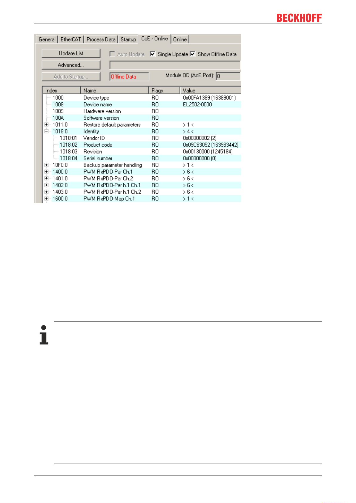
Fig.19: “CoE Online” tab
The figure above shows the CoE objects available in device “EL2502”, ranging from 0x1000 to 0x1600. The
subindices for 0x1018 are expanded.
Data management and function “NoCoeStorage”
Some parameters, particularly the setting parameters of the slave, are configurable and writeable. This can
be done in write or read mode
• via the System Manager (Fig. “CoE Online” tab) by clicking
This is useful for commissioning of the system/slaves. Click on the row of the index to be
parameterized and enter a value in the “SetValue” dialog.
• from the control system/PLC via ADS, e.g. through blocks from the TcEtherCAT.lib library
This is recommended for modifications while the system is running or if no System Manager or
operating staff are available.
Data management
If slave CoE parameters are modified online, Beckhoff devices store any changes in a fail-safe
manner in the EEPROM, i.e. the modified CoE parameters are still available after a restart.
The situation may be different with other manufacturers.
An EEPROM is subject to a limited lifetime with respect to write operations. From typically 100,000
write operations onwards it can no longer be guaranteed that new (changed) data are reliably saved
or are still readable. This is irrelevant for normal commissioning. However, if CoE parameters are
continuously changed via ADS at machine runtime, it is quite possible for the lifetime limit to be
reached. Support for the NoCoeStorage function, which suppresses the saving of changed CoE values, depends on the firmware version.
Please refer to the technical data in this documentation as to whether this applies to the respective
device.
• If the function is supported: the function is activated by entering the code word 0x12345678 once
in CoE 0xF008 and remains active as long as the code word is not changed. After switching the
device on it is then inactive. Changed CoE values are not saved in the EEPROM and can thus
be changed any number of times.
• Function is not supported: continuous changing of CoE values is not permissible in view of the
lifetime limit.
EL204438 Version: 1.0
Page 39

Startup list
Changes in the local CoE list of the terminal are lost if the terminal is replaced. If a terminal is replaced with a new Beckhoff terminal, it will have the default settings. It is therefore advisable to link
all changes in the CoE list of an EtherCAT slave with the Startup list of the slave, which is processed whenever the EtherCAT fieldbus is started. In this way a replacement EtherCAT slave can
automatically be parameterized with the specifications of the user.
If EtherCAT slaves are used which are unable to store local CoE values permanently, the Startup
list must be used.
Recommended approach for manual modification of CoE parameters
• Make the required change in the System Manager
The values are stored locally in the EtherCAT slave
• If the value is to be stored permanently, enter it in the Startup list.
The order of the Startup entries is usually irrelevant.
Basics communication
Fig.20: Startup list in the TwinCAT System Manager
The Startup list may already contain values that were configured by the System Manager based on the ESI
specifications. Additional application-specific entries can be created.
Online/offline list
While working with the TwinCAT System Manager, a distinction has to be made whether the EtherCAT
device is “available”, i.e. switched on and linked via EtherCAT and therefore online, or whether a
configuration is created offline without connected slaves.
In both cases a CoE list as shown in Fig. “CoE online tab” is displayed. The connectivity is shown as offline/
online.
• If the slave is offline
◦ The offline list from the ESI file is displayed. In this case modifications are not meaningful or
possible.
◦ The configured status is shown under Identity.
◦ No firmware or hardware version is displayed, since these are features of the physical device.
◦ Offline is shown in red.
EL2044 39Version: 1.0
Page 40

Basics communication
Fig.21: Offline list
• If the slave is online
◦ The actual current slave list is read. This may take several seconds, depending on the size and
cycle time.
◦ The actual identity is displayed
◦ The firmware and hardware version of the equipment according to the electronic information is
displayed
◦ Online is shown in green.
Fig.22: Online list
EL204440 Version: 1.0
Page 41

Basics communication
Channel-based order
The CoE list is available in EtherCAT devices that usually feature several functionally equivalent channels.
For example, a 4-channel analog 0...10V input terminal also has four logical channels and therefore four
identical sets of parameter data for the channels. In order to avoid having to list each channel in the
documentation, the placeholder “n” tends to be used for the individual channel numbers.
In the CoE system 16 indices, each with 255 subindices, are generally sufficient for representing all channel
parameters. The channel-based order is therefore arranged in 16
dec
/10
steps. The parameter range
hex
0x8000 exemplifies this:
• Channel 0: parameter range 0x8000:00 ... 0x800F:255
• Channel 1: parameter range 0x8010:00 ... 0x801F:255
• Channel 2: parameter range 0x8020:00 ... 0x802F:255
• ...
This is generally written as 0x80n0.
Detailed information on the CoE interface can be found in the EtherCAT system documentation on the
Beckhoff website.
EL2044 41Version: 1.0
Page 42

Basics communication
3.6 Distributed Clock
The distributed clock represents a local clock in the EtherCAT slave controller (ESC) with the following
characteristics:
• Unit 1 ns
• Zero point 1.1.2000 00:00
• Size 64 bit (sufficient for the next 584 years; however, some EtherCAT slaves only offer 32-bit support,
i.e. the variable overflows after approx. 4.2 seconds)
• The EtherCAT master automatically synchronizes the local clock with the master clock in the EtherCAT
bus with a precision of < 100 ns.
For detailed information please refer to the EtherCAT system description.
EL204442 Version: 1.0
Page 43

Mounting and wiring
4 Mounting and wiring
4.1 Instructions for ESD protection
NOTE
Destruction of the devices by electrostatic discharge possible!
The devices contain components at risk from electrostatic discharge caused by improper handling.
• Please ensure you are electrostatically discharged and avoid touching the contacts of the device directly.
• Avoid contact with highly insulating materials (synthetic fibers, plastic film etc.).
• Surroundings (working place, packaging and personnel) should by grounded probably, when handling
with the devices.
• Each assembly must be terminated at the right hand end with an EL9011 or EL9012 bus end cap, to ensure the protection class and ESD protection.
Fig.23: Spring contacts of the Beckhoff I/O components
4.2 Installation on mounting rails
WARNING
Risk of electric shock and damage of device!
Bring the bus terminal system into a safe, powered down state before starting installation, disassembly or
wiring of the bus terminals!
EL2044 43Version: 1.0
Page 44

Mounting and wiring
Assembly
Fig.24: Attaching on mounting rail
The bus coupler and bus terminals are attached to commercially available 35mm mounting rails (DIN rails
according to EN60715) by applying slight pressure:
1. First attach the fieldbus coupler to the mounting rail.
2. The bus terminals are now attached on the right-hand side of the fieldbus coupler. Join the components with tongue and groove and push the terminals against the mounting rail, until the lock clicks
onto the mounting rail.
If the terminals are clipped onto the mounting rail first and then pushed together without tongue and
groove, the connection will not be operational! When correctly assembled, no significant gap should
be visible between the housings.
Fixing of mounting rails
The locking mechanism of the terminals and couplers extends to the profile of the mounting rail. At
the installation, the locking mechanism of the components must not come into conflict with the fixing
bolts of the mounting rail. To mount the mounting rails with a height of 7.5mm under the terminals
and couplers, you should use flat mounting connections (e.g. countersunk screws or blind rivets).
EL204444 Version: 1.0
Page 45

Mounting and wiring
Disassembly
Fig.25: Disassembling of terminal
Each terminal is secured by a lock on the mounting rail, which must be released for disassembly:
1. Pull the terminal by its orange-colored lugs approximately 1cm away from the mounting rail. In doing
so for this terminal the mounting rail lock is released automatically and you can pull the terminal out of
the bus terminal block easily without excessive force.
2. Grasp the released terminal with thumb and index finger simultaneous at the upper and lower grooved
housing surfaces and pull the terminal out of the bus terminal block.
Connections within a bus terminal block
The electric connections between the Bus Coupler and the Bus Terminals are automatically realized by
joining the components:
• The six spring contacts of the K-Bus/E-Bus deal with the transfer of the data and the supply of the Bus
Terminal electronics.
• The power contacts deal with the supply for the field electronics and thus represent a supply rail within
the bus terminal block. The power contacts are supplied via terminals on the Bus Coupler (up to 24V)
or for higher voltages via power feed terminals.
Power Contacts
During the design of a bus terminal block, the pin assignment of the individual Bus Terminals must
be taken account of, since some types (e.g. analog Bus Terminals or digital 4-channel Bus Terminals) do not or not fully loop through the power contacts. Power Feed Terminals (KL91xx, KL92xx
or EL91xx, EL92xx) interrupt the power contacts and thus represent the start of a new supply rail.
PE power contact
The power contact labeled PE can be used as a protective earth. For safety reasons this contact mates first
when plugging together, and can ground short-circuit currents of up to 125A.
EL2044 45Version: 1.0
Page 46

Mounting and wiring
Fig.26: Power contact on left side
NOTE
Possible damage of the device
Note that, for reasons of electromagnetic compatibility, the PE contacts are capacitatively coupled to the
mounting rail. This may lead to incorrect results during insulation testing or to damage on the terminal (e.g.
disruptive discharge to the PE line during insulation testing of a consumer with a nominal voltage of 230V).
For insulation testing, disconnect the PE supply line at the Bus Coupler or the Power Feed Terminal! In order to decouple further feed points for testing, these Power Feed Terminals can be released and pulled at
least 10mm from the group of terminals.
WARNING
Risk of electric shock!
The PE power contact must not be used for other potentials!
EL204446 Version: 1.0
Page 47

Mounting and wiring
4.3 Installation instructions for enhanced mechanical load capacity
WARNING
Risk of injury through electric shock and damage to the device!
Bring the Bus Terminal system into a safe, de-energized state before starting mounting, disassembly or
wiring of the Bus Terminals!
Additional checks
The terminals have undergone the following additional tests:
Verification Explanation
Vibration 10 frequency runs in 3 axes
6 Hz < f < 60 Hz displacement 0.35 mm, constant amplitude
60.1Hz<f<500Hz acceleration 5g, constant amplitude
Shocks 1000 shocks in each direction, in 3 axes
25 g, 6 ms
Additional installation instructions
For terminals with enhanced mechanical load capacity, the following additional installation instructions apply:
• The enhanced mechanical load capacity is valid for all permissible installation positions
• Use a mounting rail according to EN 60715 TH35-15
• Fix the terminal segment on both sides of the mounting rail with a mechanical fixture, e.g. an earth
terminal or reinforced end clamp
• The maximum total extension of the terminal segment (without coupler) is:
64 terminals (12mm mounting with) or 32 terminals (24mm mounting with)
• Avoid deformation, twisting, crushing and bending of the mounting rail during edging and installation of
the rail
• The mounting points of the mounting rail must be set at 5 cm intervals
• Use countersunk head screws to fasten the mounting rail
• The free length between the strain relief and the wire connection should be kept as short as possible. A
distance of approx. 10cm should be maintained to the cable duct.
4.4 Connection
4.4.1 Connection system
WARNING
Risk of electric shock and damage of device!
Bring the bus terminal system into a safe, powered down state before starting installation, disassembly or
wiring of the bus terminals!
Overview
The Bus Terminal system offers different connection options for optimum adaptation to the respective
application:
• The terminals of ELxxxx and KLxxxx series with standard wiring include electronics and connection
level in a single enclosure.
EL2044 47Version: 1.0
Page 48

Mounting and wiring
• The terminals of ESxxxx and KSxxxx series feature a pluggable connection level and enable steady
wiring while replacing.
• The High Density Terminals (HD Terminals) include electronics and connection level in a single
enclosure and have advanced packaging density.
Standard wiring (ELxxxx / KLxxxx)
Fig.27: Standard wiring
The terminals of ELxxxx and KLxxxx series have been tried and tested for years.
They feature integrated screwless spring force technology for fast and simple assembly.
Pluggable wiring (ESxxxx / KSxxxx)
Fig.28: Pluggable wiring
The terminals of ESxxxx and KSxxxx series feature a pluggable connection level.
The assembly and wiring procedure is the same as for the ELxxxx and KLxxxx series.
The pluggable connection level enables the complete wiring to be removed as a plug connector from the top
of the housing for servicing.
The lower section can be removed from the terminal block by pulling the unlocking tab.
Insert the new component and plug in the connector with the wiring. This reduces the installation time and
eliminates the risk of wires being mixed up.
The familiar dimensions of the terminal only had to be changed slightly. The new connector adds about 3
mm. The maximum height of the terminal remains unchanged.
A tab for strain relief of the cable simplifies assembly in many applications and prevents tangling of individual
connection wires when the connector is removed.
Conductor cross sections between 0.08mm2 and 2.5mm2 can continue to be used with the proven spring
force technology.
The overview and nomenclature of the product names for ESxxxx and KSxxxx series has been retained as
known from ELxxxx and KLxxxx series.
EL204448 Version: 1.0
Page 49

Mounting and wiring
High Density Terminals (HD Terminals)
Fig.29: High Density Terminals
The Bus Terminals from these series with 16 terminal points are distinguished by a particularly compact
design, as the packaging density is twice as large as that of the standard 12mm Bus Terminals. Massive
conductors and conductors with a wire end sleeve can be inserted directly into the spring loaded terminal
point without tools.
Wiring HD Terminals
The High Density Terminals of the ELx8xx and KLx8xx series doesn't support pluggable wiring.
Ultrasonically “bonded” (ultrasonically welded) conductors
Ultrasonically “bonded” conductors
It is also possible to connect the Standard and High Density Terminals with ultrasonically
“bonded” (ultrasonically welded) conductors. In this case, please note the tables concerning the
wire-size width below!
EL2044 49Version: 1.0
Page 50

Mounting and wiring
4.4.2 Wiring
WARNING
Risk of electric shock and damage of device!
Bring the bus terminal system into a safe, powered down state before starting installation, disassembly or
wiring of the Bus Terminals!
Terminals for standard wiring ELxxxx/KLxxxx and for pluggable wiring ESxxxx/KSxxxx
Fig.30: Connecting a cable on a terminal point
Up to eight terminal points enable the connection of solid or finely stranded cables to the Bus Terminal. The
terminal points are implemented in spring force technology. Connect the cables as follows:
1. Open a terminal point by pushing a screwdriver straight against the stop into the square opening
above the terminal point. Do not turn the screwdriver or move it alternately (don't toggle).
2. The wire can now be inserted into the round terminal opening without any force.
3. The terminal point closes automatically when the pressure is released, holding the wire securely and
permanently.
See the following table for the suitable wire size width.
Terminal housing ELxxxx, KLxxxx ESxxxx, KSxxxx
Wire size width (single core wires) 0.08 ... 2.5mm
Wire size width (fine-wire conductors) 0.08 ... 2.5mm
Wire size width (conductors with a wire end sleeve) 0.14 ... 1.5mm
2
2
2
0.08 ... 2.5mm
0,08 ... 2.5mm
0.14 ... 1.5mm
2
2
2
Wire stripping length 8 ... 9mm 9 ... 10mm
High Density Terminals (HD Terminals [}49]) with 16 terminal points
The conductors of the HD Terminals are connected without tools for single-wire conductors using the direct
plug-in technique, i.e. after stripping the wire is simply plugged into the terminal point. The cables are
released, as usual, using the contact release with the aid of a screwdriver. See the following table for the
suitable wire size width.
EL204450 Version: 1.0
Page 51

Mounting and wiring
Terminal housing High Density Housing
Wire size width (single core wires) 0.08 ... 1.5mm
Wire size width (fine-wire conductors) 0.25 ... 1.5mm
Wire size width (conductors with a wire end sleeve) 0.14 ... 0.75mm
Wire size width (ultrasonically “bonded" conductors) only 1.5mm
2
2
2
2
Wire stripping length 8 ... 9mm
4.4.3 Shielding
Shielding
Encoder, analog sensors and actors should always be connected with shielded, twisted paired
wires.
4.5 Installation positions
NOTE
Constraints regarding installation position and operating temperature range
Please refer to the technical data for a terminal to ascertain whether any restrictions regarding the installation position and/or the operating temperature range have been specified. When installing high power dissipation terminals ensure that an adequate spacing is maintained between other components above and below the terminal in order to guarantee adequate ventilation!
Optimum installation position (standard)
The optimum installation position requires the mounting rail to be installed horizontally and the connection
surfaces of the EL/KL terminals to face forward (see Fig. Recommended distances for standard installation
position). The terminals are ventilated from below, which enables optimum cooling of the electronics through
convection. “From below” is relative to the acceleration of gravity.
EL2044 51Version: 1.0
Page 52

Mounting and wiring
Fig.31: Recommended distances for standard installation position
Compliance with the distances shown in Fig. Recommended distances for standard installation position is
recommended.
Other installation positions
All other installation positions are characterized by different spatial arrangement of the mounting rail - see
Fig “Other installation positions”.
The minimum distances to ambient specified above also apply to these installation positions.
EL204452 Version: 1.0
Page 53
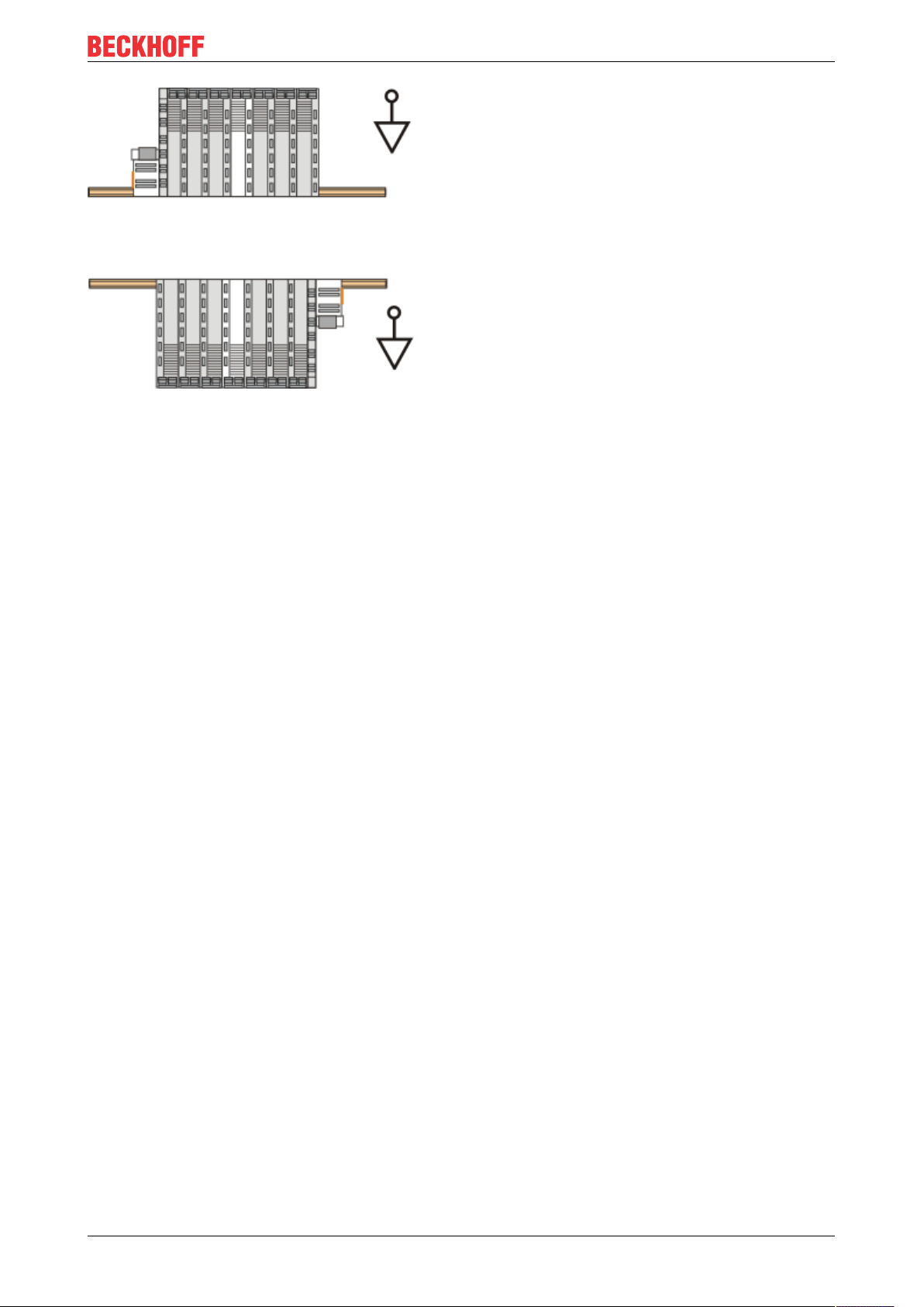
Fig.32: Other installation positions
Mounting and wiring
EL2044 53Version: 1.0
Page 54

Mounting and wiring
4.6 Positioning of passive Terminals
Hint for positioning of passive terminals in the bus terminal block
EtherCAT Terminals (ELxxxx / ESxxxx), which do not take an active part in data transfer within the
bus terminal block are so called passive terminals. The passive terminals have no current consumption out of the E-Bus.
To ensure an optimal data transfer, you must not directly string together more than two passive terminals!
Examples for positioning of passive terminals (highlighted)
Fig.33: Correct positioning
Fig.34: Incorrect positioning
EL204454 Version: 1.0
Page 55

Commissioning
5 Commissioning
5.1 TwinCAT Quick Start
TwinCAT is a development environment for real-time control including multi-PLC system, NC axis control,
programming and operation. The whole system is mapped through this environment and enables access to a
programming environment (including compilation) for the controller. Individual digital or analog inputs or
outputs can also be read or written directly, in order to verify their functionality, for example.
For further information please refer to http://infosys.beckhoff.com:
• EtherCAT Systemmanual:
Fieldbus Components → EtherCAT Terminals → EtherCAT System Documentation → Setup in the
TwinCAT System Manager
• TwinCAT2 → TwinCAT System Manager → I/O - Configuration
• In particular, TwinCAT driver installation:
Fieldbus components → Fieldbus Cards and Switches → FC900x – PCI Cards for Ethernet →
Installation
Devices contain the terminals for the actual configuration. All configuration data can be entered directly via
editor functions (offline) or via the “Scan” function (online):
• “offline”: The configuration can be customized by adding and positioning individual components.
These can be selected from a directory and configured.
◦ The procedure for offline mode can be found under http://infosys.beckhoff.com:
TwinCAT2 → TwinCAT System Manager → IO - Configuration → Adding an I/O Device
• “online”: The existing hardware configuration is read
◦ See also http://infosys.beckhoff.com:
Fieldbus components → Fieldbus cards and switches → FC900x – PCI Cards for Ethernet →
Installation → Searching for devices
The following relationship is envisaged from user PC to the individual control elements:
EL2044 55Version: 1.0
Page 56

Commissioning
Fig.35: Relationship between user side (commissioning) and installation
The user inserting of certain components (I/O device, terminal, box...) is the same in TwinCAT2 and
TwinCAT3. The descriptions below relate to the online procedure.
Sample configuration (actual configuration)
Based on the following sample configuration, the subsequent subsections describe the procedure for
TwinCAT2 and TwinCAT3:
• Control system (PLC) CX2040 including CX2100-0004 power supply unit
• Connected to the CX2040 on the right (E-bus):
EL1004 (4-channel digital input terminal 24VDC)
• Linked via the X001 port (RJ-45): EK1100 EtherCAT Coupler
• Connected to the EK1100 EtherCAT coupler on the right (E-bus):
EL2008 (8-channel digital output terminal 24VDC;0.5A)
• (Optional via X000: a link to an external PC for the user interface)
EL204456 Version: 1.0
Page 57
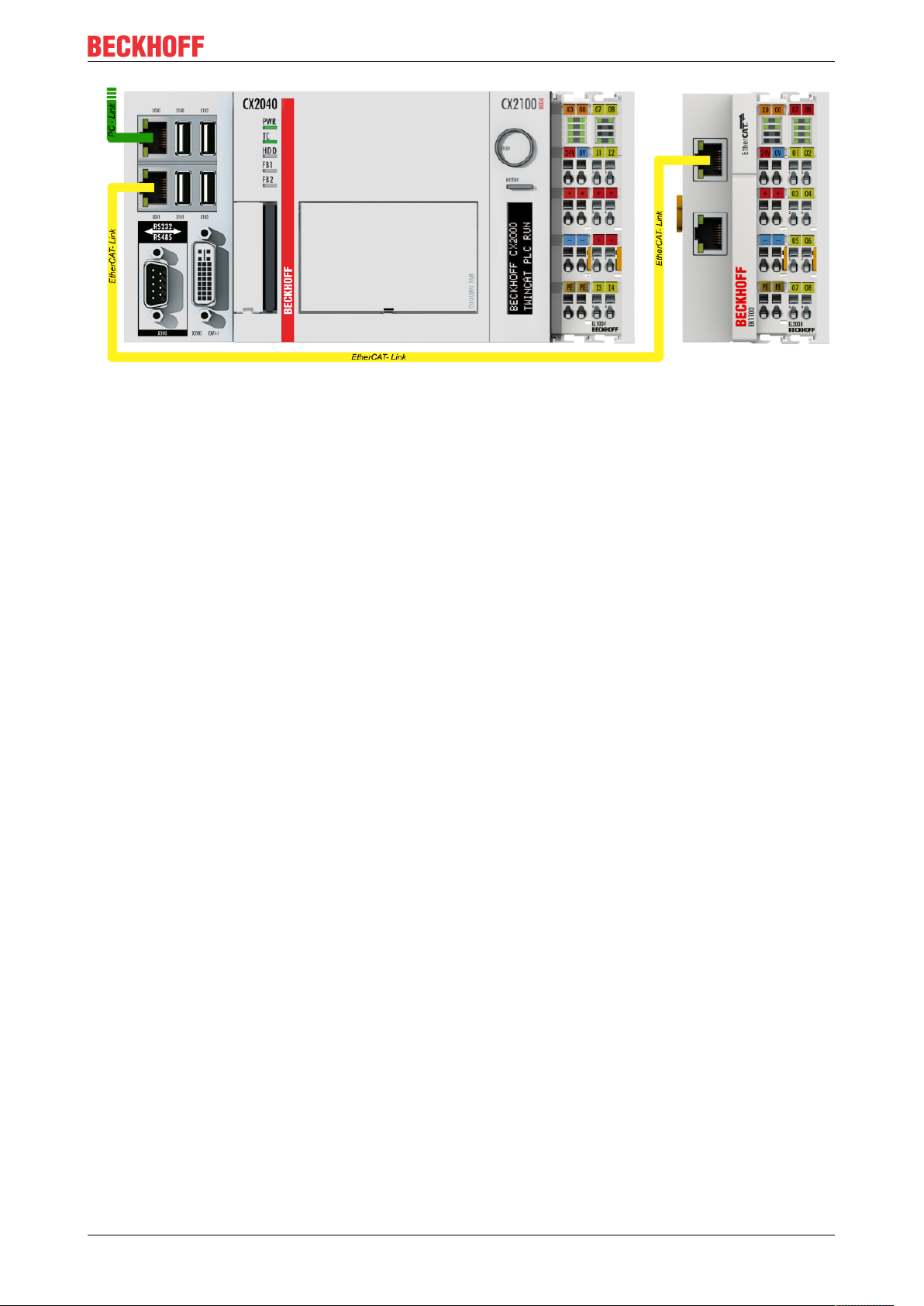
Commissioning
Fig.36: Control configuration with Embedded PC, input (EL1004) and output (EL2008)
Note that all combinations of a configuration are possible; for example, the EL1004 terminal could also be
connected after the coupler, or the EL2008 terminal could additionally be connected to the CX2040 on the
right, in which case the EK1100 coupler wouldn’t be necessary.
EL2044 57Version: 1.0
Page 58

Commissioning
5.1.1 TwinCAT2
Startup
TwinCAT basically uses two user interfaces: the TwinCAT System Manager for communication with the
electromechanical components and TwinCAT PLC Control for the development and compilation of a
controller. The starting point is the TwinCAT System Manager.
After successful installation of the TwinCAT system on the PC to be used for development, the TwinCAT2
System Manager displays the following user interface after startup:
Fig.37: Initial TwinCAT2 user interface
Generally, TwinCAT can be used in local or remote mode. Once the TwinCAT system including the user
interface (standard) is installed on the respective PLC, TwinCAT can be used in local mode and thereby the
next step is “Insert Device [}60]”.
If the intention is to address the TwinCAT runtime environment installed on a PLC as development
environment remotely from another system, the target system must be made known first. In the menu under
“Actions” → “Choose Target System...”, via the symbol “ ” or the “F8” key, open the following window:
EL204458 Version: 1.0
Page 59

Fig.38: Selection of the target system
Use “Search (Ethernet)...” to enter the target system. Thus a next dialog opens to either:
Commissioning
• enter the known computer name after “Enter Host Name / IP:” (as shown in red)
• perform a “Broadcast Search” (if the exact computer name is not known)
• enter the known computer IP or AmsNetID.
Fig.39: Specify the PLC for access by the TwinCAT System Manager: selection of the target system
Once the target system has been entered, it is available for selection as follows (a password may have to be
entered):
After confirmation with “OK” the target system can be accessed via the System Manager.
EL2044 59Version: 1.0
Page 60

Commissioning
Adding devices
In the configuration tree of the TwinCAT2 System Manager user interface on the left, select “I/ODevices”
and then right-click to open a context menu and select “ScanDevices…”, or start the action in the menu bar
via . The TwinCAT System Manager may first have to be set to “Configmode” via or via menu
“Actions” → “Set/Reset TwinCAT to Config Mode…” (Shift + F4).
Fig.40: Select “Scan Devices...”
Confirm the warning message, which follows, and select “EtherCAT” in the dialog:
Fig.41: Automatic detection of I/O devices: selection the devices to be integrated
Confirm the message “Find new boxes”, in order to determine the terminals connected to the devices. “Free
Run” enables manipulation of input and output values in “Config mode” and should also be acknowledged.
Based on the sample configuration [}56] described at the beginning of this section, the result is as follows:
EL204460 Version: 1.0
Page 61

Commissioning
Fig.42: Mapping of the configuration in the TwinCAT2 System Manager
The whole process consists of two stages, which may be performed separately (first determine the devices,
then determine the connected elements such as boxes, terminals, etc.). A scan can also be initiated by
selecting “Device ...” from the context menu, which then reads the elements present in the configuration
below:
Fig.43: Reading of individual terminals connected to a device
This functionality is useful if the actual configuration is modified at short notice.
Programming and integrating the PLC
TwinCAT PLC Control is the development environment for the creation of the controller in different program
environments: TwinCAT PLC Control supports all languages described in IEC 61131-3. There are two textbased languages and three graphical languages.
• Text-based languages
◦ Instruction List (IL)
EL2044 61Version: 1.0
Page 62

Commissioning
◦ Structured Text (ST)
• Graphical languages
◦ Function Block Diagram (FBD)
◦ Ladder Diagram (LD)
◦ The Continuous Function Chart Editor (CFC)
◦ Sequential Function Chart (SFC)
The following section refers to Structured Text (ST).
After starting TwinCAT PLC Control, the following user interface is shown for an initial project:
Fig.44: TwinCAT PLC Control after startup
Sample variables and a sample program have been created and stored under the name “PLC_example.pro”:
EL204462 Version: 1.0
Page 63

Commissioning
Fig.45: Sample program with variables after a compile process (without variable integration)
Warning 1990 (missing “VAR_CONFIG”) after a compile process indicates that the variables defined as
external (with the ID “AT%I*” or “AT%Q*”) have not been assigned. After successful compilation, TwinCAT
PLC Control creates a “*.tpy” file in the directory in which the project was stored. This file (“*.tpy”) contains
variable assignments and is not known to the System Manager, hence the warning. Once the System
Manager has been notified, the warning no longer appears.
First, integrate the TwinCAT PLC Control project in the System Manager via the context menu of the PLC
configuration; right-click and select “Append PLC Project…”:
Fig.46: Appending the TwinCAT PLC Control project
EL2044 63Version: 1.0
Page 64

Commissioning
Select the PLC configuration “PLC_example.tpy” in the browser window that opens. The project including the
two variables identified with “AT” are then integrated in the configuration tree of the System Manager:
Fig.47: PLC project integrated in the PLC configuration of the System Manager
The two variables “bEL1004_Ch4” and “nEL2008_value” can now be assigned to certain process objects of
the I/O configuration.
Assigning variables
Open a window for selecting a suitable process object (PDO) via the context menu of a variable of the
integrated project “PLC_example” and via “Modify Link...” “Standard”:
Fig.48: Creating the links between PLC variables and process objects
In the window that opens, the process object for the variable “bEL1004_Ch4” of type BOOL can be selected
from the PLC configuration tree:
EL204464 Version: 1.0
Page 65
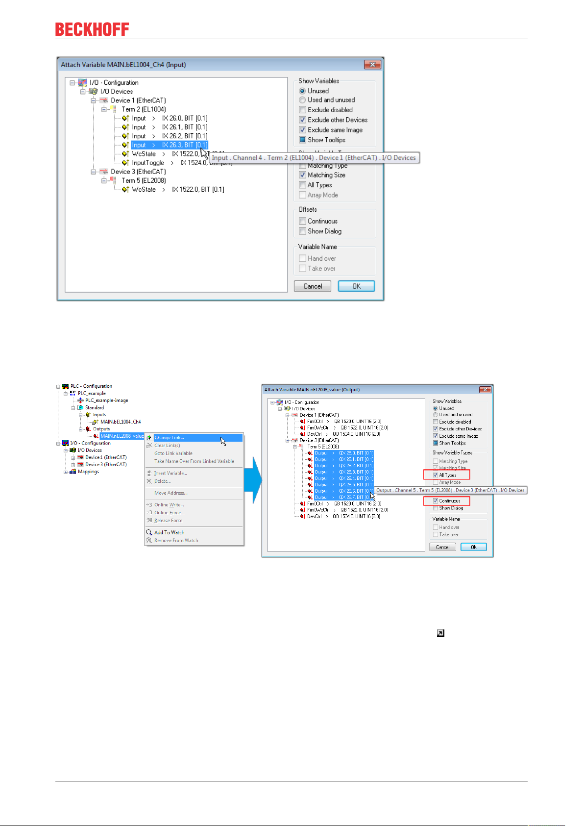
Commissioning
Fig.49: Selecting PDO of type BOOL
According to the default setting, certain PDO objects are now available for selection. In this sample the input
of channel 4 of the EL1004 terminal is selected for linking. In contrast, the checkbox “All types” must be
ticked for creating the link for the output variables, in order to allocate a set of eight separate output bits to a
byte variable. The following diagram shows the whole process:
Fig.50: Selecting several PDOs simultaneously: activate “Continuous” and “All types”
Note that the “Continuous” checkbox was also activated. This is designed to allocate the bits contained in the
byte of the variable “nEL2008_value” sequentially to all eight selected output bits of the EL2008 terminal. In
this way it is possible to subsequently address all eight outputs of the terminal in the program with a byte
corresponding to bit 0 for channel 1 to bit 7 for channel 8 of the PLC. A special symbol ( ) at the yellow or
red object of the variable indicates that a link exists. The links can also be checked by selecting a “Goto Link
Variable” from the context menu of a variable. The object opposite, in this case the PDO, is automatically
selected:
EL2044 65Version: 1.0
Page 66

Commissioning
Fig.51: Application of a “Goto Link” variable, using “MAIN.bEL1004_Ch4” as a sample
The process of assigning variables to the PDO is completed via the menu selection “Actions” → “Generate
Mappings”, key Ctrl+M or by clicking on the symbol in the menu.
This can be visualized in the configuration:
The process of creating links can also take place in the opposite direction, i.e. starting with individual PDOs
to variable. However, in this example it would then not be possible to select all output bits for the EL2008,
since the terminal only makes individual digital outputs available. If a terminal has a byte, word, integer or
similar PDO, it is possible to allocate this a set of bit-standardized variables (type “BOOL”). Here, too, a
“Goto Link Variable” from the context menu of a PDO can be executed in the other direction, so that the
respective PLC instance can then be selected.
Activation of the configuration
The allocation of PDO to PLC variables has now established the connection from the controller to the inputs
and outputs of the terminals. The configuration can now be activated. First, the configuration can be verified
via (or via “Actions” → “Check Configuration”). If no error is present, the configuration can be
activated via (or via “Actions” → “Activate Configuration…”) to transfer the System Manager settings
to the runtime system. Confirm the messages “Old configurations are overwritten!” and “Restart TwinCAT
system in Run mode” with “OK”.
A few seconds later the real-time status is displayed at the bottom right in the System Manager.
The PLC system can then be started as described below.
Starting the controller
Starting from a remote system, the PLC control has to be linked with the Embedded PC over Ethernet via
“Online” → “Choose Run-Time System…”:
EL204466 Version: 1.0
Page 67

Commissioning
Fig.52: Choose target system (remote)
In this sample “Runtime system 1 (port 801)” is selected and confirmed. Link the PLC with the real-time
system via menu option “Online” → “Login”, the F11 key or by clicking on the symbol .The control
program can then be loaded for execution. This results in the message “No program on the controller!
Should the new program be loaded?”, which should be acknowledged with “Yes”. The runtime environment
is ready for the program start:
EL2044 67Version: 1.0
Page 68

Commissioning
Fig.53: PLC Control logged in, ready for program startup
The PLC can now be started via “Online” → “Run”, F5 key or .
5.1.2 TwinCAT 3
Startup
TwinCAT makes the development environment areas available together with Microsoft Visual Studio: after
startup, the project folder explorer appears on the left in the general window area (cf. “TwinCAT System
Manager” of TwinCAT2) for communication with the electromechanical components.
After successful installation of the TwinCAT system on the PC to be used for development, TwinCAT3
(shell) displays the following user interface after startup:
EL204468 Version: 1.0
Page 69
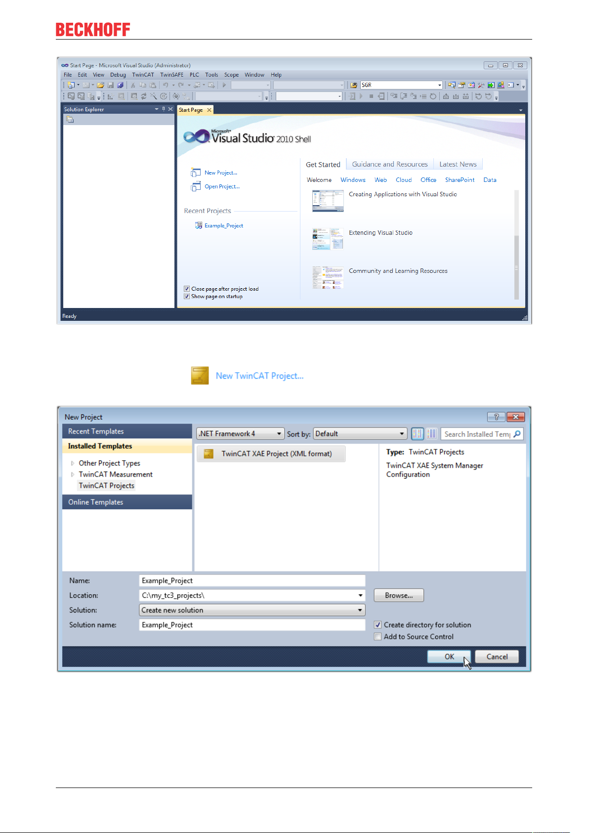
Commissioning
Fig.54: Initial TwinCAT3 user interface
First create a new project via (or under “File”→“New”→ “Project…”). In the
following dialog make the corresponding entries as required (as shown in the diagram):
Fig.55: Create new TwinCAT project
The new project is then available in the project folder explorer:
EL2044 69Version: 1.0
Page 70

Commissioning
Fig.56: New TwinCAT3 project in the project folder explorer
Generally, TwinCAT can be used in local or remote mode. Once the TwinCAT system including the user
interface (standard) is installed on the respective PLC, TwinCAT can be used in local mode and thereby the
next step is “Insert Device [}71]”.
If the intention is to address the TwinCAT runtime environment installed on a PLC as development
environment remotely from another system, the target system must be made known first. Via the symbol in
the menu bar:
expand the pull-down menu:
and open the following window:
Fig.57: Selection dialog: Choose the target system
EL204470 Version: 1.0
Page 71
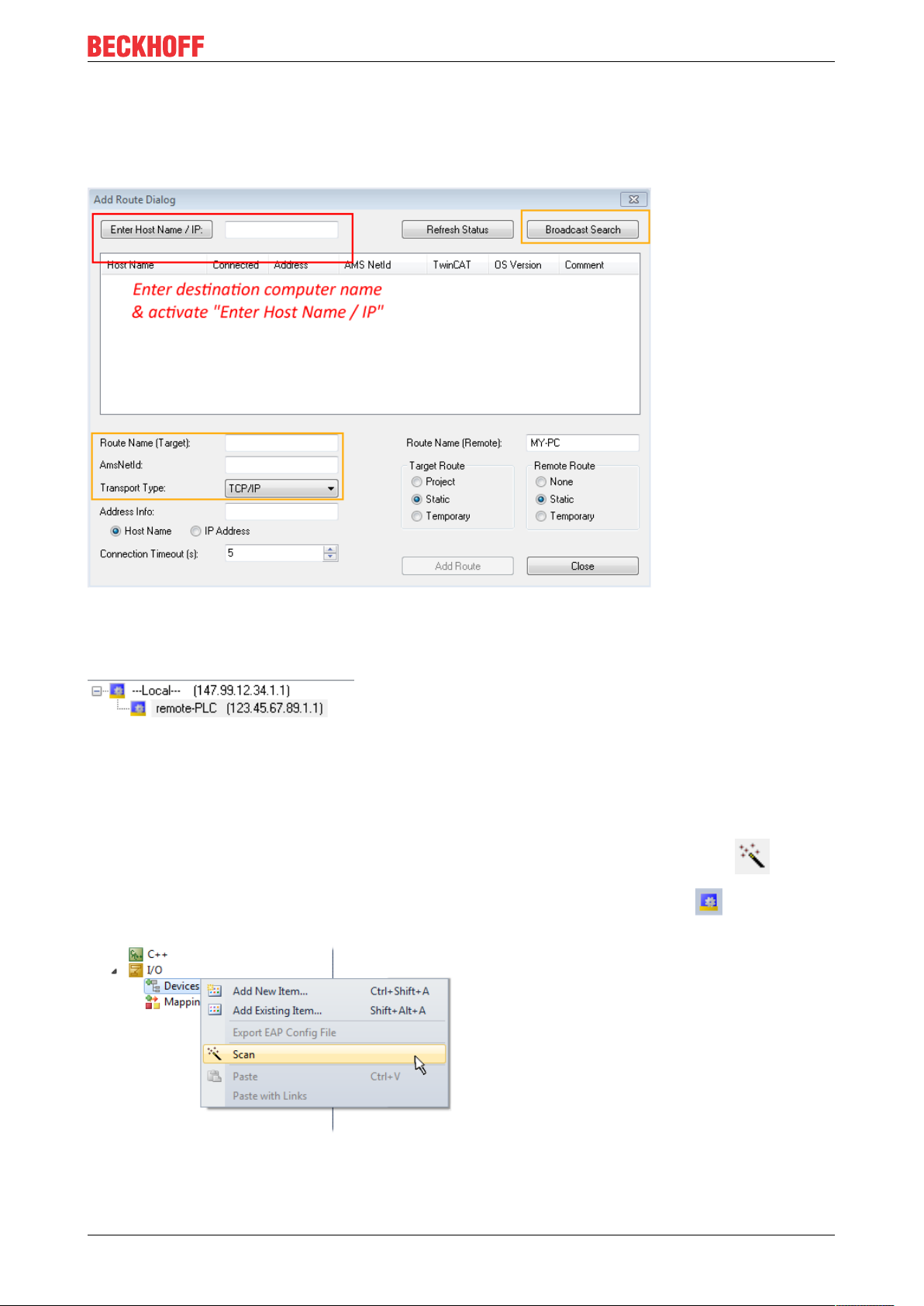
Use “Search (Ethernet)...” to enter the target system. Thus a next dialog opens to either:
• enter the known computer name after “Enter Host Name / IP:” (as shown in red)
• perform a “Broadcast Search” (if the exact computer name is not known)
• enter the known computer IP or AmsNetID.
Commissioning
Fig.58: Specify the PLC for access by the TwinCAT System Manager: selection of the target system
Once the target system has been entered, it is available for selection as follows (a password may have to be
entered):
After confirmation with “OK” the target system can be accessed via the Visual Studio shell.
Adding devices
In the project folder explorer of the Visual Studio shell user interface on the left, select “Devices” within
element “I/O”, then right-click to open a context menu and select “Scan” or start the action via in the
menu bar. The TwinCAT System Manager may first have to be set to “Config mode” via or via the
menu “TwinCAT” → “Restart TwinCAT (Config mode)”.
Fig.59: Select “Scan”
Confirm the warning message, which follows, and select “EtherCAT” in the dialog:
EL2044 71Version: 1.0
Page 72
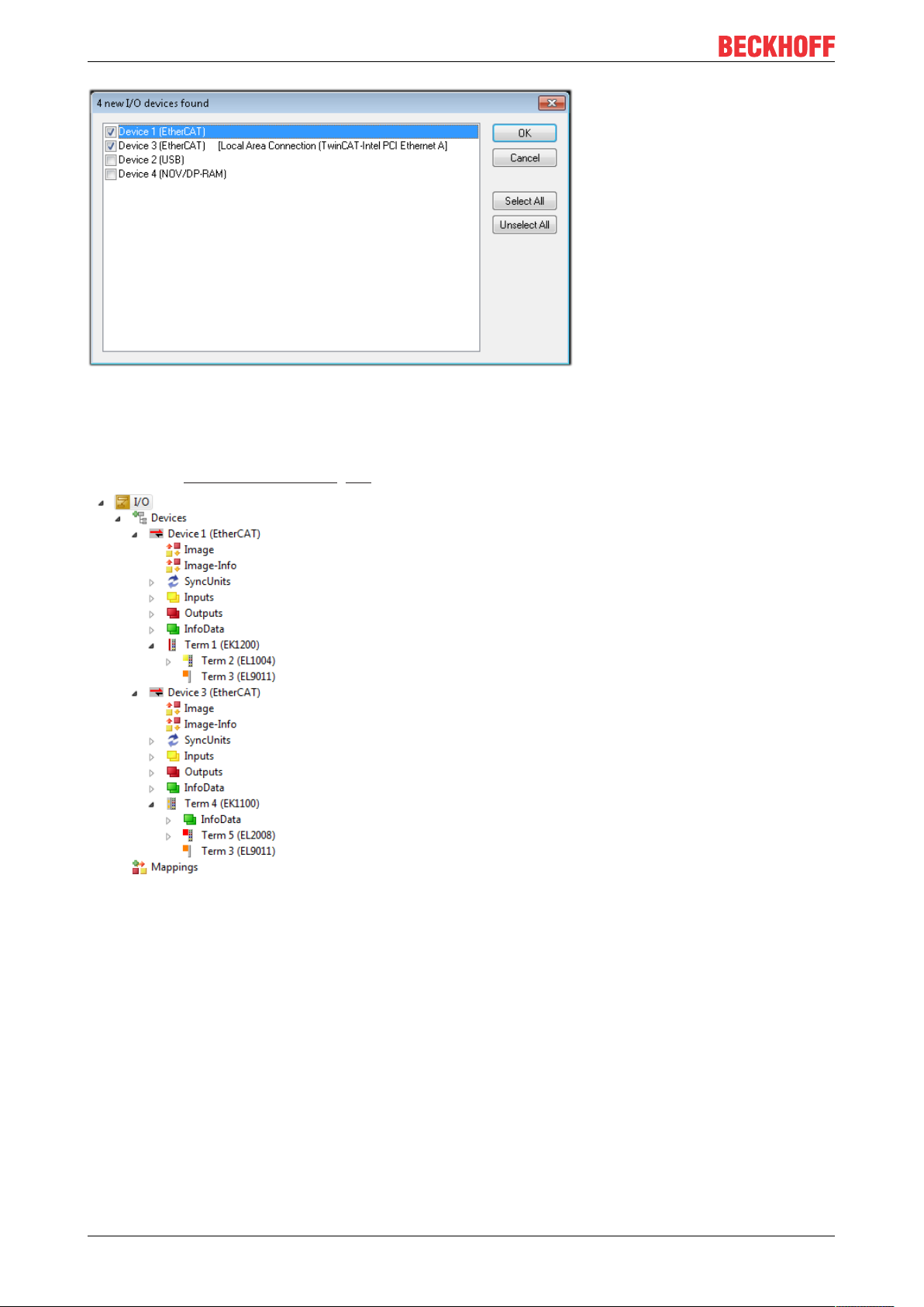
Commissioning
Fig.60: Automatic detection of I/O devices: selection the devices to be integrated
Confirm the message “Find new boxes”, in order to determine the terminals connected to the devices. “Free
Run” enables manipulation of input and output values in “Config mode” and should also be acknowledged.
Based on the sample configuration [}56] described at the beginning of this section, the result is as follows:
Fig.61: Mapping of the configuration in VS shell of the TwinCAT3 environment
The whole process consists of two stages, which may be performed separately (first determine the devices,
then determine the connected elements such as boxes, terminals, etc.). A scan can also be initiated by
selecting “Device ...” from the context menu, which then reads the elements present in the configuration
below:
EL204472 Version: 1.0
Page 73
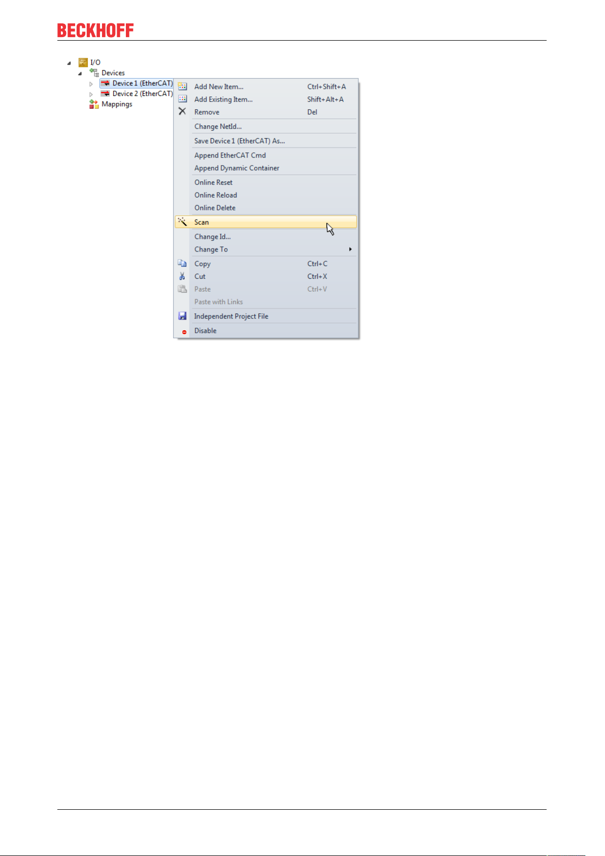
Commissioning
Fig.62: Reading of individual terminals connected to a device
This functionality is useful if the actual configuration is modified at short notice.
Programming the PLC
TwinCAT PLC Control is the development environment for the creation of the controller in different program
environments: TwinCAT PLC Control supports all languages described in IEC 61131-3. There are two textbased languages and three graphical languages.
• Text-based languages
◦ Instruction List (IL)
◦ Structured Text (ST)
• Graphical languages
◦ Function Block Diagram (FBD)
◦ Ladder Diagram (LD)
◦ The Continuous Function Chart Editor (CFC)
◦ Sequential Function Chart (SFC)
The following section refers to Structured Text (ST).
In order to create a programming environment, a PLC subproject is added to the project sample via the
context menu of “PLC” in the project folder explorer by selecting “Add New Item….”:
EL2044 73Version: 1.0
Page 74

Commissioning
Fig.63: Adding the programming environment in “PLC”
In the dialog that opens select “Standard PLC project” and enter “PLC_example” as project name, for
example, and select a corresponding directory:
Fig.64: Specifying the name and directory for the PLC programming environment
The “Main” program, which already exists by selecting “Standard PLC project”, can be opened by doubleclicking on “PLC_example_project” in “POUs”. The following user interface is shown for an initial project:
EL204474 Version: 1.0
Page 75

Commissioning
Fig.65: Initial “Main” program of the standard PLC project
To continue, sample variables and a sample program have now been created:
EL2044 75Version: 1.0
Page 76

Commissioning
Fig.66: Sample program with variables after a compile process (without variable integration)
The control program is now created as a project folder, followed by the compile process:
Fig.67: Start program compilation
The following variables, identified in the ST/ PLC program with “AT%”, are then available in under
“Assignments” in the project folder explorer:
Assigning variables
Via the menu of an instance - variables in the “PLC” context, use the “Modify Link…” option to open a
window for selecting a suitable process object (PDO) for linking:
EL204476 Version: 1.0
Page 77

Commissioning
Fig.68: Creating the links between PLC variables and process objects
In the window that opens, the process object for the variable “bEL1004_Ch4” of type BOOL can be selected
from the PLC configuration tree:
Fig.69: Selecting PDO of type BOOL
According to the default setting, certain PDO objects are now available for selection. In this sample the input
of channel 4 of the EL1004 terminal is selected for linking. In contrast, the checkbox “All types” must be
ticked for creating the link for the output variables, in order to allocate a set of eight separate output bits to a
byte variable. The following diagram shows the whole process:
EL2044 77Version: 1.0
Page 78

Commissioning
Fig.70: Selecting several PDOs simultaneously: activate “Continuous” and “All types”
Note that the “Continuous” checkbox was also activated. This is designed to allocate the bits contained in the
byte of the variable “nEL2008_value” sequentially to all eight selected output bits of the EL2008 terminal. In
this way it is possible to subsequently address all eight outputs of the terminal in the program with a byte
corresponding to bit 0 for channel 1 to bit 7 for channel 8 of the PLC. A special symbol ( ) at the yellow or
red object of the variable indicates that a link exists. The links can also be checked by selecting a “Goto Link
Variable” from the context menu of a variable. The object opposite, in this case the PDO, is automatically
selected:
Fig.71: Application of a “Goto Link” variable, using “MAIN.bEL1004_Ch4” as a sample
The process of creating links can also take place in the opposite direction, i.e. starting with individual PDOs
to variable. However, in this example it would then not be possible to select all output bits for the EL2008,
since the terminal only makes individual digital outputs available. If a terminal has a byte, word, integer or
EL204478 Version: 1.0
Page 79

Commissioning
similar PDO, it is possible to allocate this a set of bit-standardized variables (type “BOOL”). Here, too, a
“Goto Link Variable” from the context menu of a PDO can be executed in the other direction, so that the
respective PLC instance can then be selected.
Note on the type of variable assignment
The following type of variable assignment can only be used from TwinCAT version V3.1.4024.4 onwards and is only available for terminals with a microcontroller.
In TwinCAT it is possible to create a structure from the mapped process data of a terminal. An instance of
this structure can then be created in the PLC, so it is possible to access the process data directly from the
PLC without having to declare own variables.
The procedure for the EL3001 1-channel analog input terminal -10...+10V is shown as an example.
1. First the required process data must be selected in the “Process data” tab in TwinCAT.
2. After that, the PLC data type must be generated in the tab “PLC” via the check box.
3. The data type in the “Data Type” field can then be copied using the “Copy” button.
Fig.72: Creating a PLC data type
4. An instance of the data structure of the copied data type must then be created in the PLC.
Fig.73: Instance_of_struct
5. Then the project folder must be created. This can be done either via the key combination “CTRL +
Shift + B” or via the “Build” tab in TwinCAT.
6. The structure in the “PLC” tab of the terminal must then be linked to the created instance.
EL2044 79Version: 1.0
Page 80
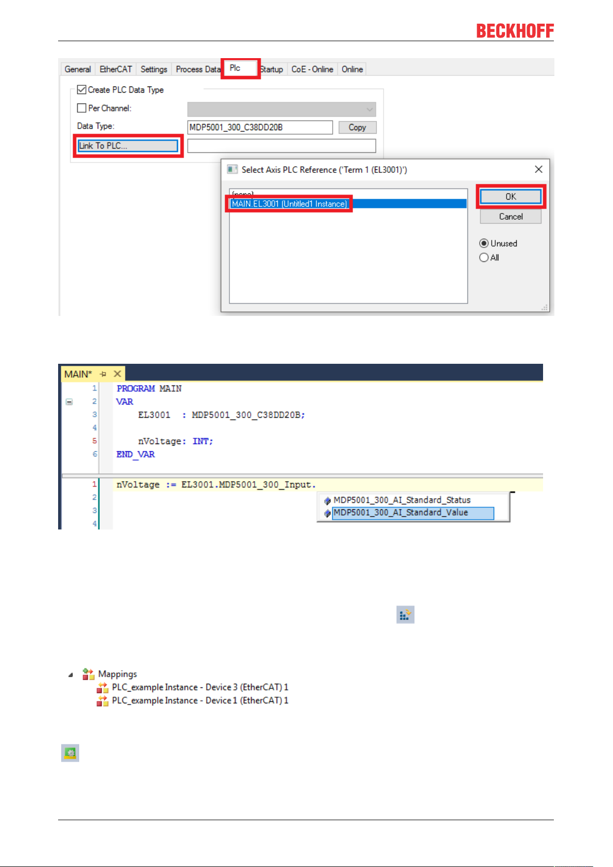
Commissioning
Fig.74: Linking the structure
7. In the PLC the process data can then be read or written via the structure in the program code.
Fig.75: Reading a variable from the structure of the process data
Activation of the configuration
The allocation of PDO to PLC variables has now established the connection from the controller to the inputs
and outputs of the terminals. The configuration can now be activated with or via the menu under
“TwinCAT” in order to transfer settings of the development environment to the runtime system. Confirm the
messages “Old configurations are overwritten!” and “Restart TwinCAT system in Run mode” with “OK”. The
corresponding assignments can be seen in the project folder explorer:
A few seconds later the corresponding status of the Run mode is displayed in the form of a rotating symbol
at the bottom right of the VS shell development environment. The PLC system can then be started as
described below.
EL204480 Version: 1.0
Page 81

Commissioning
Starting the controller
Select the menu option “PLC” → “Login” or click on to link the PLC with the real-time system and load
the control program for execution. This results in the message No program on the controller! Should the new
program be loaded?, which should be acknowledged with “Yes”. The runtime environment is ready for
program start by click on symbol , the “F5” key or via “PLC” in the menu selecting “Start”. The started
programming environment shows the runtime values of individual variables:
Fig.76: TwinCAT development environment (VS shell): logged-in, after program startup
The two operator control elements for stopping and logout result in the required action
(accordingly also for stop “Shift + F5”, or both actions can be selected via the PLC menu).
5.2 TwinCAT Development Environment
The Software for automation TwinCAT (The Windows Control and Automation Technology) will be
distinguished into:
• TwinCAT2: System Manager (Configuration) & PLC Control (Programming)
• TwinCAT3: Enhancement of TwinCAT2 (Programming and Configuration takes place via a common
Development Environment)
Details:
• TwinCAT2:
◦ Connects I/O devices to tasks in a variable-oriented manner
◦ Connects tasks to tasks in a variable-oriented manner
◦ Supports units at the bit level
◦ Supports synchronous or asynchronous relationships
◦ Exchange of consistent data areas and process images
◦ Datalink on NT - Programs by open Microsoft Standards (OLE, OCX, ActiveX, DCOM+, etc.)
EL2044 81Version: 1.0
Page 82
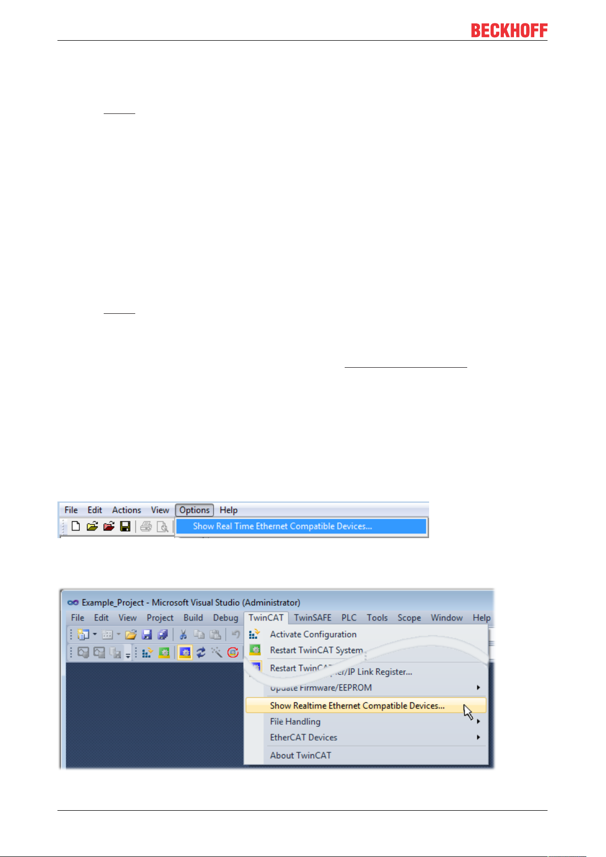
Commissioning
◦ Integration of IEC 61131-3-Software-SPS, Software- NC and Software-CNC within Windows
NT/2000/XP/Vista, Windows 7, NT/XP Embedded, CE
◦ Interconnection to all common fieldbusses
◦ More…
Additional features:
• TwinCAT3 (eXtended Automation):
◦ Visual-Studio®-Integration
◦ Choice of the programming language
◦ Supports object orientated extension of IEC 61131-3
◦ Usage of C/C++ as programming language for real time applications
◦ Connection to MATLAB®/Simulink®
◦ Open interface for expandability
◦ Flexible run-time environment
◦ Active support of Multi-Core- und 64-Bit-Operatingsystem
◦ Automatic code generation and project creation with the TwinCAT Automation Interface
◦ More…
Within the following sections commissioning of the TwinCAT Development Environment on a PC System for
the control and also the basically functions of unique control elements will be explained.
Please see further information to TwinCAT2 and TwinCAT3 at http://infosys.beckhoff.com.
5.2.1 Installation of the TwinCAT real-time driver
In order to assign real-time capability to a standard Ethernet port of an IPC controller, the Beckhoff real-time
driver has to be installed on this port under Windows.
This can be done in several ways. One option is described here.
In the System Manager call up the TwinCAT overview of the local network interfaces via Options → Show
Real Time Ethernet Compatible Devices.
Fig.77: System Manager “Options” (TwinCAT2)
This have to be called up by the Menü “TwinCAT” within the TwinCAT3 environment:
Fig.78: Call up under VS Shell (TwinCAT3)
EL204482 Version: 1.0
Page 83
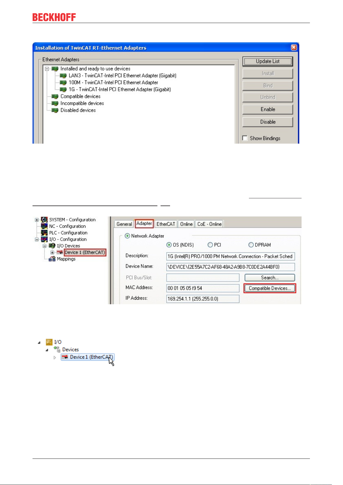
Commissioning
The following dialog appears:
Fig.79: Overview of network interfaces
Interfaces listed under “Compatible devices” can be assigned a driver via the “Install” button. A driver should
only be installed on compatible devices.
A Windows warning regarding the unsigned driver can be ignored.
Alternatively an EtherCAT-device can be inserted first of all as described in chapter Offline configuration
creation, section “Creating the EtherCAT device” [}92] in order to view the compatible ethernet ports via its
EtherCAT properties (tab “Adapter”, button “Compatible Devices…”):
Fig.80: EtherCAT device properties(TwinCAT2): click on “Compatible Devices…” of tab “Adapte””
TwinCAT 3: the properties of the EtherCAT device can be opened by double click on “Device .. (EtherCAT)”
within the Solution Explorer under “I/O”:
After the installation the driver appears activated in the Windows overview for the network interface
(Windows Start → System Properties → Network)
EL2044 83Version: 1.0
Page 84
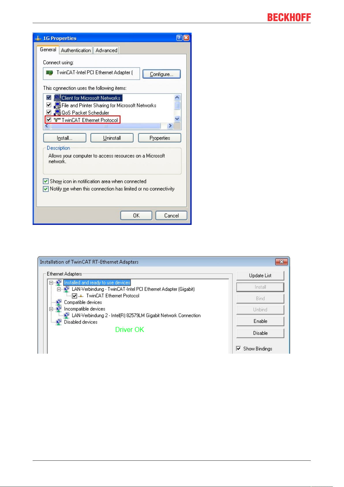
Commissioning
Fig.81: Windows properties of the network interface
A correct setting of the driver could be:
Fig.82: Exemplary correct driver setting for the Ethernet port
Other possible settings have to be avoided:
EL204484 Version: 1.0
Page 85
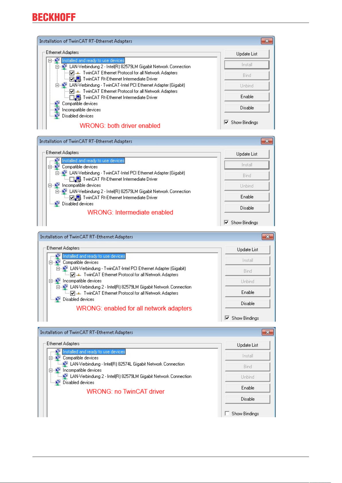
Commissioning
Fig.83: Incorrect driver settings for the Ethernet port
EL2044 85Version: 1.0
Page 86

Commissioning
IP address of the port used
IP address/DHCP
In most cases an Ethernet port that is configured as an EtherCAT device will not transport general
IP packets. For this reason and in cases where an EL6601 or similar devices are used it is useful to
specify a fixed IP address for this port via the “Internet Protocol TCP/IP” driver setting and to disable
DHCP. In this way the delay associated with the DHCP client for the Ethernet port assigning itself a
default IP address in the absence of a DHCP server is avoided. A suitable address space is
192.168.x.x, for example.
Fig.84: TCP/IP setting for the Ethernet port
EL204486 Version: 1.0
Page 87

Commissioning
5.2.2 Notes regarding ESI device description
Installation of the latest ESI device description
The TwinCAT EtherCAT master/System Manager needs the device description files for the devices to be
used in order to generate the configuration in online or offline mode. The device descriptions are contained
in the so-called ESI files (EtherCAT Slave Information) in XML format. These files can be requested from the
respective manufacturer and are made available for download. An *.xml file may contain several device
descriptions.
The ESI files for Beckhoff EtherCAT devices are available on the Beckhoff website.
The ESI files should be stored in the TwinCAT installation directory.
Default settings:
• TwinCAT2: C:\TwinCAT\IO\EtherCAT
• TwinCAT3: C:\TwinCAT\3.1\Config\Io\EtherCAT
The files are read (once) when a new System Manager window is opened, if they have changed since the
last time the System Manager window was opened.
A TwinCAT installation includes the set of Beckhoff ESI files that was current at the time when the TwinCAT
build was created.
For TwinCAT2.11/TwinCAT3 and higher, the ESI directory can be updated from the System Manager, if the
programming PC is connected to the Internet; by
• TwinCAT2: Option → “Update EtherCAT Device Descriptions”
• TwinCAT3: TwinCAT → EtherCAT Devices → “Update Device Descriptions (via ETG Website)…”
The TwinCAT ESI Updater [}91] is available for this purpose.
ESI
The *.xml files are associated with *.xsd files, which describe the structure of the ESI XML files. To
update the ESI device descriptions, both file types should therefore be updated.
Device differentiation
EtherCAT devices/slaves are distinguished by four properties, which determine the full device identifier. For
example, the device identifier EL2521-0025-1018 consists of:
• family key “EL”
• name “2521”
• type “0025”
• and revision “1018”
Fig.85: Identifier structure
The order identifier consisting of name + type (here: EL2521-0010) describes the device function. The
revision indicates the technical progress and is managed by Beckhoff. In principle, a device with a higher
revision can replace a device with a lower revision, unless specified otherwise, e.g. in the documentation.
Each revision has its own ESI description. See further notes.
EL2044 87Version: 1.0
Page 88
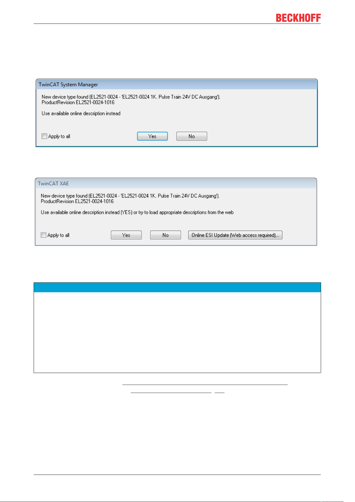
Commissioning
Online description
If the EtherCAT configuration is created online through scanning of real devices (see section Online setup)
and no ESI descriptions are available for a slave (specified by name and revision) that was found, the
System Manager asks whether the description stored in the device should be used. In any case, the System
Manager needs this information for setting up the cyclic and acyclic communication with the slave correctly.
Fig.86: OnlineDescription information window (TwinCAT2)
In TwinCAT3 a similar window appears, which also offers the Web update:
Fig.87: Information window OnlineDescription (TwinCAT3)
If possible, the Yes is to be rejected and the required ESI is to be requested from the device manufacturer.
After installation of the XML/XSD file the configuration process should be repeated.
NOTE
Changing the “usual” configuration through a scan
ü If a scan discovers a device that is not yet known to TwinCAT, distinction has to be made between two
cases. Taking the example here of the EL2521-0000 in the revision 1019
a) no ESI is present for the EL2521-0000 device at all, either for the revision 1019 or for an older revision.
The ESI must then be requested from the manufacturer (in this case Beckhoff).
b) an ESI is present for the EL2521-0000 device, but only in an older revision, e.g. 1018 or 1017.
In this case an in-house check should first be performed to determine whether the spare parts stock allows the integration of the increased revision into the configuration at all. A new/higher revision usually
also brings along new features. If these are not to be used, work can continue without reservations with
the previous revision 1018 in the configuration. This is also stated by the Beckhoff compatibility rule.
Refer in particular to the chapter “General notes on the use of Beckhoff EtherCAT IO components” and for
manual configuration to the chapter “Offline configuration creation [}92]”.
If the OnlineDescription is used regardless, the System Manager reads a copy of the device description from
the EEPROM in the EtherCAT slave. In complex slaves the size of the EEPROM may not be sufficient for the
complete ESI, in which case the ESI would be incomplete in the configurator. Therefore it’s recommended
using an offline ESI file with priority in such a case.
The System Manager creates for online recorded device descriptions a new file
“OnlineDescription0000...xml” in its ESI directory, which contains all ESI descriptions that were read online.
EL204488 Version: 1.0
Page 89

Commissioning
Fig.88: File OnlineDescription.xml created by the System Manager
Is a slave desired to be added manually to the configuration at a later stage, online created slaves are
indicated by a prepended symbol “>” in the selection list (see Figure Indication of an online recorded ESI of
EL2521 as an example).
Fig.89: Indication of an online recorded ESI of EL2521 as an example
If such ESI files are used and the manufacturer's files become available later, the file OnlineDescription.xml
should be deleted as follows:
• close all System Manager windows
• restart TwinCAT in Config mode
• delete “OnlineDescription0000...xml”
• restart TwinCAT System Manager
This file should not be visible after this procedure, if necessary press <F5> to update
OnlineDescription for TwinCAT3.x
In addition to the file described above “OnlineDescription0000...xml”, a so called EtherCAT cache
with new discovered devices is created by TwinCAT3.x, e.g. under Windows 7:
(Please note the language settings of the OS!)
You have to delete this file, too.
Faulty ESI file
If an ESI file is faulty and the System Manager is unable to read it, the System Manager brings up an
information window.
Fig.90: Information window for faulty ESI file (left: TwinCAT2; right: TwinCAT3)
EL2044 89Version: 1.0
Page 90

Commissioning
Reasons may include:
• Structure of the *.xml does not correspond to the associated *.xsd file → check your schematics
• Contents cannot be translated into a device description → contact the file manufacturer
EL204490 Version: 1.0
Page 91

Commissioning
5.2.3 TwinCAT ESI Updater
For TwinCAT2.11 and higher, the System Manager can search for current Beckhoff ESI files automatically, if
an online connection is available:
Fig.91: Using the ESI Updater (>= TwinCAT2.11)
The call up takes place under:
“Options” → “Update EtherCAT Device Descriptions”
Selection under TwinCAT3:
Fig.92: Using the ESI Updater (TwinCAT3)
The ESI Updater (TwinCAT3) is a convenient option for automatic downloading of ESI data provided by
EtherCAT manufacturers via the Internet into the TwinCAT directory (ESI = EtherCAT slave information).
TwinCAT accesses the central ESI ULR directory list stored at ETG; the entries can then be viewed in the
Updater dialog, although they cannot be changed there.
The call up takes place under:
“TwinCAT” → “EtherCAT Devices” → “Update Device Description (via ETG Website)…”.
5.2.4 Distinction between Online and Offline
The distinction between online and offline refers to the presence of the actual I/O environment (drives,
terminals, EJ-modules). If the configuration is to be prepared in advance of the system configuration as a
programming system, e.g. on a laptop, this is only possible in “Offline configuration” mode. In this case all
components have to be entered manually in the configuration, e.g. based on the electrical design.
If the designed control system is already connected to the EtherCAT system and all components are
energised and the infrastructure is ready for operation, the TwinCAT configuration can simply be generated
through “scanning” from the runtime system. This is referred to as online configuration.
In any case, during each startup the EtherCAT master checks whether the slaves it finds match the
configuration. This test can be parameterised in the extended slave settings. Refer to note “Installation of
the latest ESI-XML device description” [}87].
For preparation of a configuration:
• the real EtherCAT hardware (devices, couplers, drives) must be present and installed
• the devices/modules must be connected via EtherCAT cables or in the terminal/ module strand in the
same way as they are intended to be used later
EL2044 91Version: 1.0
Page 92

Commissioning
• the devices/modules be connected to the power supply and ready for communication
• TwinCAT must be in CONFIG mode on the target system.
The online scan process consists of:
• detecting the EtherCAT device [}97] (Ethernet port at the IPC)
• detecting the connected EtherCAT devices [}98]. This step can be carried out independent of the
preceding step
• troubleshooting [}101]
The scan with existing configuration [}102] can also be carried out for comparison.
5.2.5 OFFLINE configuration creation
Creating the EtherCAT device
Create an EtherCAT device in an empty System Manager window.
Fig.93: Append EtherCAT device (left: TwinCAT2; right: TwinCAT3)
Select type “EtherCAT” for an EtherCAT I/O application with EtherCAT slaves. For the present publisher/
subscriber service in combination with an EL6601/EL6614 terminal select “EtherCAT Automation Protocol
via EL6601”.
Fig.94: Selecting the EtherCAT connection (TwinCAT2.11, TwinCAT3)
Then assign a real Ethernet port to this virtual device in the runtime system.
Fig.95: Selecting the Ethernet port
EL204492 Version: 1.0
Page 93

Commissioning
This query may appear automatically when the EtherCAT device is created, or the assignment can be set/
modified later in the properties dialog; see Fig. “EtherCAT device properties (TwinCAT2)”.
Fig.96: EtherCAT device properties (TwinCAT2)
TwinCAT 3: the properties of the EtherCAT device can be opened by double click on “Device .. (EtherCAT)”
within the Solution Explorer under “I/O”:
Selecting the Ethernet port
Ethernet ports can only be selected for EtherCAT devices for which the TwinCAT real-time driver is
installed. This has to be done separately for each port. Please refer to the respective installation
page [}82].
Defining EtherCAT slaves
Further devices can be appended by right-clicking on a device in the configuration tree.
Fig.97: Appending EtherCAT devices (left: TwinCAT2; right: TwinCAT3)
The dialog for selecting a new device opens. Only devices for which ESI files are available are displayed.
Only devices are offered for selection that can be appended to the previously selected device. Therefore the
physical layer available for this port is also displayed (Fig. “Selection dialog for new EtherCAT device”, A). In
the case of cable-based Fast-Ethernet physical layer with PHY transfer, then also only cable-based devices
are available, as shown in Fig. “Selection dialog for new EtherCAT device”. If the preceding device has
several free ports (e.g. EK1122 or EK1100), the required port can be selected on the right-hand side (A).
Overview of physical layer
• “Ethernet”: cable-based 100BASE-TX: EK couplers, EP boxes, devices with RJ45/M8/M12 connector
EL2044 93Version: 1.0
Page 94

Commissioning
• “E-Bus”: LVDS “terminal bus”, “EJ-module”: EL/ES terminals, various modular modules
The search field facilitates finding specific devices (since TwinCAT2.11 or TwinCAT3).
Fig.98: Selection dialog for new EtherCAT device
By default only the name/device type is used as selection criterion. For selecting a specific revision of the
device the revision can be displayed as “Extended Information”.
Fig.99: Display of device revision
In many cases several device revisions were created for historic or functional reasons, e.g. through
technological advancement. For simplification purposes (see Fig. “Selection dialog for new EtherCAT
device”) only the last (i.e. highest) revision and therefore the latest state of production is displayed in the
selection dialog for Beckhoff devices. To show all device revisions available in the system as ESI
descriptions tick the “Show Hidden Devices” check box, see Fig. “Display of previous revisions”.
EL204494 Version: 1.0
Page 95

Fig.100: Display of previous revisions
Device selection based on revision, compatibility
The ESI description also defines the process image, the communication type between master and
slave/device and the device functions, if applicable. The physical device (firmware, if available) has
to support the communication queries/settings of the master. This is backward compatible, i.e.
newer devices (higher revision) should be supported if the EtherCAT master addresses them as an
older revision. The following compatibility rule of thumb is to be assumed for Beckhoff EtherCAT
Terminals/ Boxes/ EJ-modules:
device revision in the system >= device revision in the configuration
This also enables subsequent replacement of devices without changing the configuration (different
specifications are possible for drives).
Commissioning
Example
If an EL2521-0025-1018 is specified in the configuration, an EL2521-0025-1018 or higher (-1019, -1020) can
be used in practice.
Fig.101: Name/revision of the terminal
If current ESI descriptions are available in the TwinCAT system, the last revision offered in the selection
dialog matches the Beckhoff state of production. It is recommended to use the last device revision when
creating a new configuration, if current Beckhoff devices are used in the real application. Older revisions
should only be used if older devices from stock are to be used in the application.
In this case the process image of the device is shown in the configuration tree and can be parameterized as
follows: linking with the task, CoE/DC settings, plug-in definition, startup settings, ...
EL2044 95Version: 1.0
Page 96
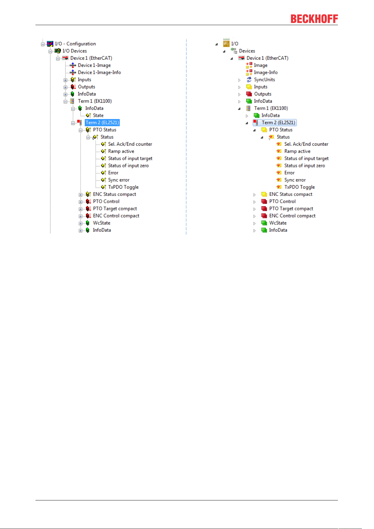
Commissioning
Fig.102: EtherCAT terminal in the TwinCAT tree (left: TwinCAT2; right: TwinCAT3)
EL204496 Version: 1.0
Page 97
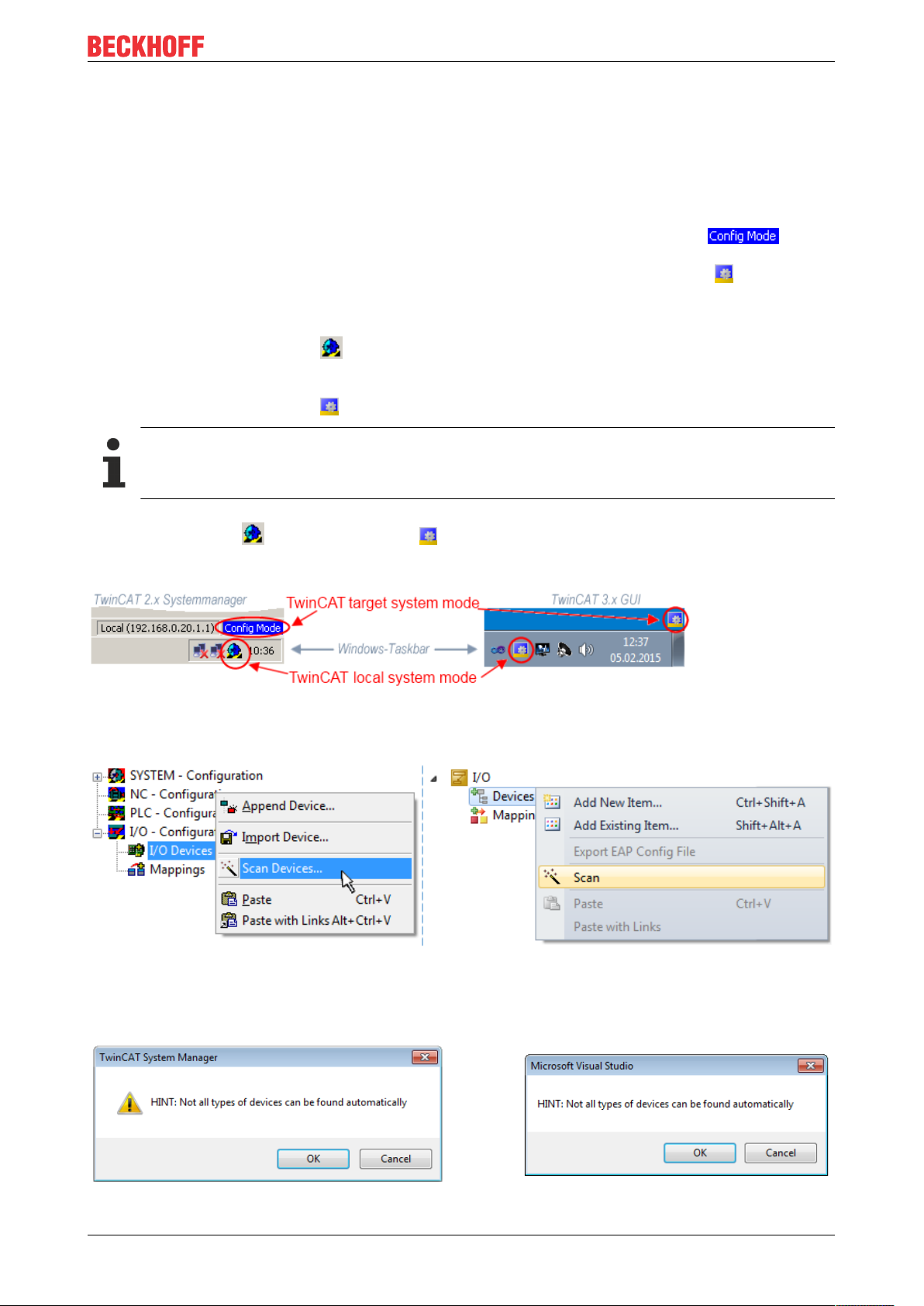
Commissioning
5.2.6 ONLINE configuration creation
Detecting/scanning of the EtherCAT device
The online device search can be used if the TwinCAT system is in CONFIG mode. This can be indicated by
a symbol right below in the information bar:
• on TwinCAT2 by a blue display “Config Mode” within the System Manager window: .
• on TwinCAT3 within the user interface of the development environment by a symbol .
TwinCAT can be set into this mode:
• TwinCAT2: by selection of in the Menubar or by “Actions” → “Set/Reset TwinCATtoConfig
Mode…”
• TwinCAT3: by selection of in the Menubar or by “TwinCAT” → “RestartTwinCAT(ConfigMode)”
Online scanning in Config mode
The online search is not available in RUN mode (production operation). Note the differentiation between TwinCAT programming system and TwinCAT target system.
The TwinCAT2 icon ( ) or TwinCAT3 icon ( ) within the Windows-Taskbar always shows the
TwinCAT mode of the local IPC. Compared to that, the System Manager window of TwinCAT2 or the user
interface of TwinCAT3 indicates the state of the target system.
Fig.103: Differentiation local/target system (left: TwinCAT2; right: TwinCAT3)
Right-clicking on “I/O Devices” in the configuration tree opens the search dialog.
Fig.104: Scan Devices (left: TwinCAT2; right: TwinCAT3)
This scan mode attempts to find not only EtherCAT devices (or Ethernet ports that are usable as such), but
also NOVRAM, fieldbus cards, SMB etc. However, not all devices can be found automatically.
Fig.105: Note for automatic device scan (left: TwinCAT2; right: TwinCAT3)
EL2044 97Version: 1.0
Page 98
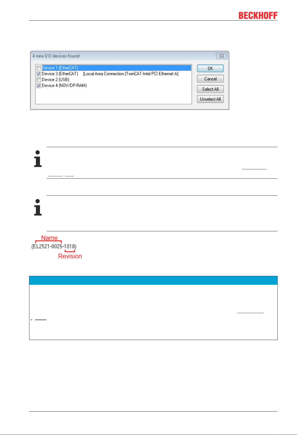
Commissioning
Ethernet ports with installed TwinCAT real-time driver are shown as “RT Ethernet” devices. An EtherCAT
frame is sent to these ports for testing purposes. If the scan agent detects from the response that an
EtherCAT slave is connected, the port is immediately shown as an “EtherCAT Device” .
Fig.106: Detected Ethernet devices
Via respective checkboxes devices can be selected (as illustrated in Fig. “Detected Ethernet devices” e.g.
Device 3 and Device 4 were chosen). After confirmation with “OK” a device scan is suggested for all selected
devices, see Fig.: “Scan query after automatic creation of an EtherCAT device”.
Selecting the Ethernet port
Ethernet ports can only be selected for EtherCAT devices for which the TwinCAT real-time driver is
installed. This has to be done separately for each port. Please refer to the respective installation
page [}82].
Detecting/Scanning the EtherCAT devices
Online scan functionality
During a scan the master queries the identity information of the EtherCAT slaves from the slave
EEPROM. The name and revision are used for determining the type. The respective devices are located in the stored ESI data and integrated in the configuration tree in the default state defined
there.
Fig.107: Example default state
NOTE
Slave scanning in practice in series machine production
The scanning function should be used with care. It is a practical and fast tool for creating an initial configuration as a basis for commissioning. In series machine production or reproduction of the plant, however, the
function should no longer be used for the creation of the configuration, but if necessary for comparison
[}102] with the defined initial configuration.Background: since Beckhoff occasionally increases the revision
version of the delivered products for product maintenance reasons, a configuration can be created by such
a scan which (with an identical machine construction) is identical according to the device list; however, the
respective device revision may differ from the initial configuration.
Example:
Company A builds the prototype of a machine B, which is to be produced in series later on. To do this the
prototype is built, a scan of the IO devices is performed in TwinCAT and the initial configuration “B.tsm” is
created. The EL2521-0025 EtherCAT terminal with the revision 1018 is located somewhere. It is thus built
into the TwinCAT configuration in this way:
EL204498 Version: 1.0
Page 99

Commissioning
Fig.108: Installing EthetCAT terminal with revision -1018
Likewise, during the prototype test phase, the functions and properties of this terminal are tested by the
programmers/commissioning engineers and used if necessary, i.e. addressed from the PLC “B.pro” or the
NC. (the same applies correspondingly to the TwinCAT3 solution files).
The prototype development is now completed and series production of machine B starts, for which Beckhoff
continues to supply the EL2521-0025-0018. If the commissioning engineers of the series machine production
department always carry out a scan, a B configuration with the identical contents results again for each
machine. Likewise, A might create spare parts stores worldwide for the coming series-produced machines
with EL2521-0025-1018 terminals.
After some time Beckhoff extends the EL2521-0025 by a new feature C. Therefore the FW is changed,
outwardly recognizable by a higher FW version and a new revision -1019. Nevertheless the new device
naturally supports functions and interfaces of the predecessor version(s); an adaptation of “B.tsm” or even
“B.pro” is therefore unnecessary. The series-produced machines can continue to be built with “B.tsm” and
“B.pro”; it makes sense to perform a comparative scan [}102] against the initial configuration “B.tsm” in order
to check the built machine.
However, if the series machine production department now doesn’t use “B.tsm”, but instead carries out a
scan to create the productive configuration, the revision -1019 is automatically detected and built into the
configuration:
Fig.109: Detection of EtherCAT terminal with revision -1019
This is usually not noticed by the commissioning engineers. TwinCAT cannot signal anything either, since
virtually a new configuration is created. According to the compatibility rule, however, this means that no
EL2521-0025-1018 should be built into this machine as a spare part (even if this nevertheless works in the
vast majority of cases).
In addition, it could be the case that, due to the development accompanying production in company A, the
new feature C of the EL2521-0025-1019 (for example, an improved analog filter or an additional process
data for the diagnosis) is discovered and used without in-house consultation. The previous stock of spare
part devices are then no longer to be used for the new configuration “B2.tsm” created in this way. Þ if series
machine production is established, the scan should only be performed for informative purposes for
comparison with a defined initial configuration. Changes are to be made with care!
If an EtherCAT device was created in the configuration (manually or through a scan), the I/O field can be
scanned for devices/slaves.
Fig.110: Scan query after automatic creation of an EtherCAT device (left: TwinCAT2; right: TwinCAT3)
EL2044 99Version: 1.0
Page 100

Commissioning
Fig.111: Manual triggering of a device scan on a specified EtherCAT device (left: TwinCAT2; right:
TwinCAT3)
In the System Manager (TwinCAT2) or the User Interface (TwinCAT3) the scan process can be monitored
via the progress bar at the bottom in the status bar.
Fig.112: Scan progressexemplary by TwinCAT2
The configuration is established and can then be switched to online state (OPERATIONAL).
Fig.113: Config/FreeRun query (left: TwinCAT2; right: TwinCAT3)
In Config/FreeRun mode the System Manager display alternates between blue and red, and the EtherCAT
device continues to operate with the idling cycle time of 4ms (default setting), even without active task (NC,
PLC).
Fig.114: Displaying of “Free Run” and “Config Mode” toggling right below in the status bar
Fig.115: TwinCAT can also be switched to this state by using a button (left: TwinCAT2; right: TwinCAT3)
The EtherCAT system should then be in a functional cyclic state, as shown in Fig. Online display example.
EL2044100 Version: 1.0
 Loading...