

Page 1

Operating Instructions for
EL1918
TwinSAFE Terminal with 8 digital fail-safe inputs
1.2.0
2018-11-05
Version:
Date:
Page 2

Page 3

Table of contents
EL1918 3Version: 1.2.0
Table of contents
1 Foreword ....................................................................................................................................................5
1.1 Notes on the documentation..............................................................................................................5
1.2 Safety instructions .............................................................................................................................6
1.2.1 Delivery state ..................................................................................................................... 6
1.2.2 Operator's obligation to exercise diligence ........................................................................ 6
1.2.3 Description of safety symbols ............................................................................................ 7
1.3 Documentation issue status ..............................................................................................................7
1.4 Version history of the TwinSAFE product..........................................................................................8
1.5 References ........................................................................................................................................8
2 System description ...................................................................................................................................9
2.1 The Beckhoff EtherCAT Terminal system .........................................................................................9
2.1.1 EtherCAT Bus Coupler .................................................................................................... 10
2.1.2 EtherCAT Terminals ........................................................................................................ 11
2.1.3 E-bus ............................................................................................................................... 11
2.1.4 Power contacts ................................................................................................................ 11
2.2 TwinSAFE........................................................................................................................................12
2.2.1 The I/O construction kit is extended safely ...................................................................... 12
2.2.2 Safety concept ................................................................................................................. 12
2.2.3 The fail-safe principle (Fail Stop) ..................................................................................... 13
3 Product description.................................................................................................................................14
3.1 EL1918 – TwinSAFE Terminal with 8 digital fail-safe inputs ...........................................................14
3.2 Intended use....................................................................................................................................15
3.3 Technical data .................................................................................................................................17
3.4 Safety parameters ...........................................................................................................................18
3.5 Safe input ........................................................................................................................................18
3.6 Characteristic curve of the inputs ....................................................................................................19
3.7 Dimensions......................................................................................................................................20
4 Operation..................................................................................................................................................21
4.1 Environmental conditions ................................................................................................................21
4.2 Installation .......................................................................................................................................21
4.2.1 Safety instructions ........................................................................................................... 21
4.2.2 Transport / storage .......................................................................................................... 21
4.2.3 Mechanical installation..................................................................................................... 21
4.2.4 Electrical installation ........................................................................................................ 28
4.3 Configuration of the terminal in TwinCAT........................................................................................33
4.3.1 Inserting a Bus Coupler ................................................................................................... 33
4.3.2 Inserting a Bus Terminal.................................................................................................. 33
4.3.3 Adding an EL1918 ........................................................................................................... 33
4.3.4 Address settings on TwinSAFE terminals with 1023 possible addresses ....................... 34
4.3.5 Alias devices.................................................................................................................... 35
4.3.6 EL1918 parameters in TwinCAT...................................................................................... 36
4.3.7 Process image of the EL1918.......................................................................................... 38
4.3.8 Local logic function .......................................................................................................... 39
Page 4

Table of contents
EL19184 Version: 1.2.0
4.3.9 Project design limits of EL1918 ....................................................................................... 40
4.4 TwinSAFE reaction times ................................................................................................................40
4.5 Diagnosis.........................................................................................................................................43
4.5.1 Status LEDs..................................................................................................................... 43
4.5.2 Diagnostic LEDs .............................................................................................................. 43
4.5.3 Flash code display ........................................................................................................... 44
4.5.4 Diagnosis History............................................................................................................. 44
4.5.5 Diag History tab ............................................................................................................... 47
4.6 Maintenance ....................................................................................................................................48
4.7 Service life .......................................................................................................................................49
4.8 Decommissioning ............................................................................................................................49
4.9 Firmware update of TwinSAFE products.........................................................................................50
5 Appendix ..................................................................................................................................................53
5.1 Support and Service ........................................................................................................................53
5.2 Certificates.......................................................................................................................................54
Page 5

Foreword
EL1918 5Version: 1.2.0
1 Foreword
1.1 Notes on the documentation
Intended audience
This description is only intended for the use of trained specialists in control and automation engineering who
are familiar with the applicable national standards.
It is essential that the following notes and explanations are followed when installing and commissioning
these components.
The responsible staff must ensure that the application or use of the products described satisfy all the
requirements for safety, including all the relevant laws, regulations, guidelines and standards.
Origin of the document
This documentation was originally written in German. All other languages are derived from the German
original.
Currentness
Please check whether you are using the current and valid version of this document. The current version can
be downloaded from the Beckhoff homepage at http://www.beckhoff.com/english/download/twinsafe.htm.
In case of doubt, please contact Technical Support [}53].
Product features
Only the product features specified in the current user documentation are valid. Further information given on
the product pages of the Beckhoff homepage, in emails or in other publications is not authoritative.
Disclaimer
The documentation has been prepared with care. The products described are subject to cyclical revision. For
that reason the documentation is not in every case checked for consistency with performance data,
standards or other characteristics. We reserve the right to revise and change the documentation at any time
and without prior announcement. No claims for the modification of products that have already been supplied
may be made on the basis of the data, diagrams and descriptions in this documentation.
Trademarks
Beckhoff®, TwinCAT®, EtherCAT®, EtherCATP®, SafetyoverEtherCAT®, TwinSAFE®, XFC® and XTS® are
registered trademarks of and licensed by Beckhoff Automation GmbH.
Other designations used in this publication may be trademarks whose use by third parties for their own
purposes could violate the rights of the owners.
Patent Pending
The EtherCAT Technology is covered, including but not limited to the following patent applications and
patents: EP1590927, EP1789857, DE102004044764, DE102007017835 with corresponding applications or
registrations in various other countries.
The TwinCAT Technology is covered, including but not limited to the following patent applications and
patents: EP0851348, US6167425 with corresponding applications or registrations in various other countries.
Page 6

Foreword
EL19186 Version: 1.2.0
EtherCAT® and Safety over EtherCAT® are registered trademarks and patented technologies, licensed by
Beckhoff Automation GmbH, Germany.
Copyright
© Beckhoff Automation GmbH & Co. KG, Germany.
The reproduction, distribution and utilization of this document as well as the communication of its contents to
others without express authorization are prohibited.
Offenders will be held liable for the payment of damages. All rights reserved in the event of the grant of a
patent, utility model or design.
Delivery conditions
In addition, the general delivery conditions of the company Beckhoff Automation GmbH & Co. KG apply.
1.2 Safety instructions
1.2.1 Delivery state
All the components are supplied in particular hardware and software configurations appropriate for the
application. Modifications to hardware or software configurations other than those described in the
documentation are not permitted, and nullify the liability of Beckhoff Automation GmbH & Co. KG.
1.2.2 Operator's obligation to exercise diligence
The operator must ensure that
• the TwinSAFE products are only used as intended (see chapter Product description);
• the TwinSAFE products are only operated in sound condition and in working order.
• the TwinSAFE products are operated only by suitably qualified and authorized personnel.
• the personnel is instructed regularly about relevant occupational safety and environmental protection
aspects, and is familiar with the operating instructions and in particular the safety instructions contained
herein.
• the operating instructions are in good condition and complete, and always available for reference at the
location where the TwinSAFE products are used.
• none of the safety and warning notes attached to the TwinSAFE products are removed, and all notes
remain legible.
Page 7

Foreword
EL1918 7Version: 1.2.0
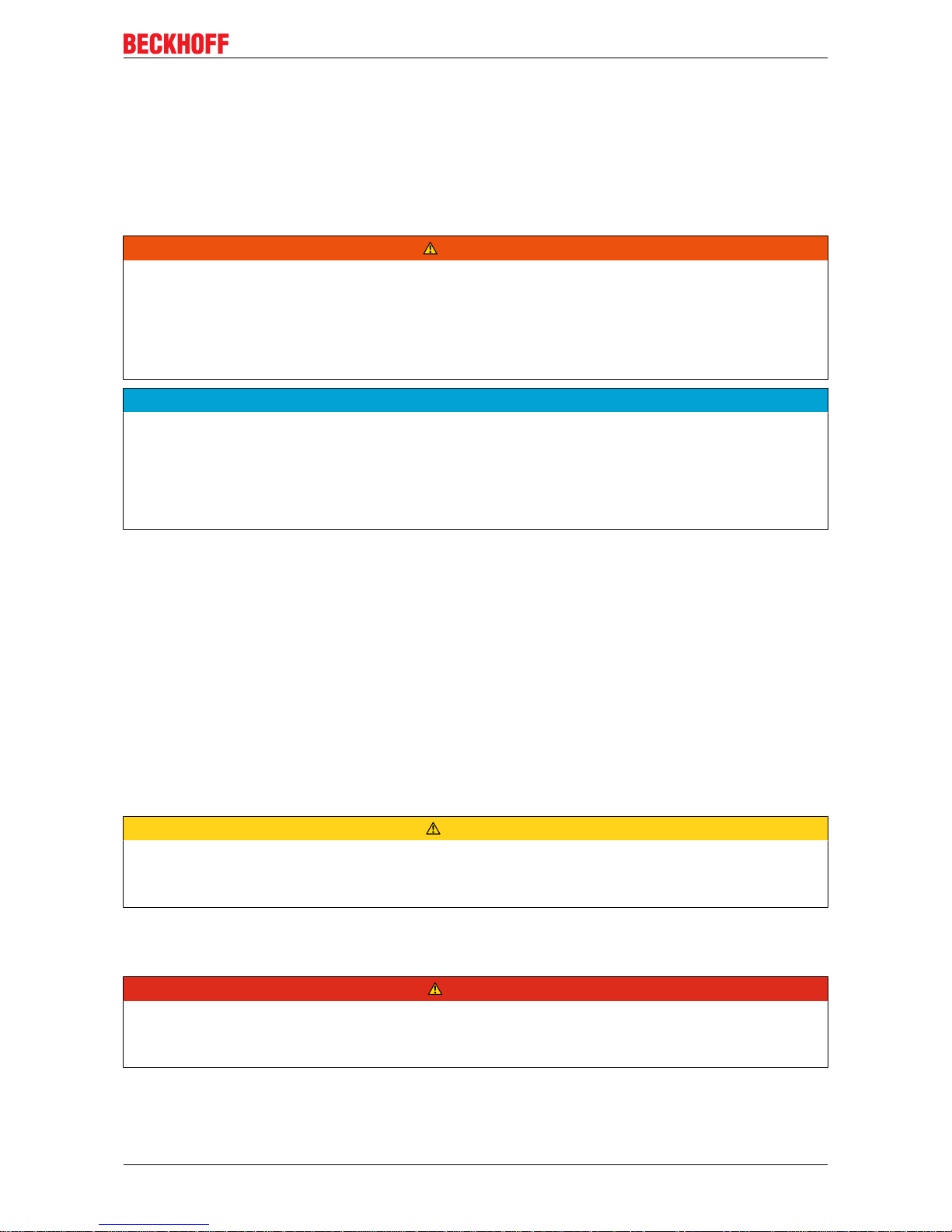
1.2.3 Description of safety symbols
In these operating instructions the following instructions are used.
These instructions must be read carefully and followed without fail!
DANGER
Serious risk of injury!
Failure to follow this safety instruction directly endangers the life and health of persons.
WARNING
Risk of injury!
Failure to follow this safety instruction endangers the life and health of persons.
CAUTION
Personal injuries!
Failure to follow this safety instruction can lead to injuries to persons.
NOTE
Damage to the environment/equipment or data loss
Failure to follow this instruction can lead to environmental damage, equipment damage or data loss.
Tip or pointer
This symbol indicates information that contributes to better understanding.
1.3 Documentation issue status
Version Comment
1.2.0 • Project design limits added
1.1.0 • Restrictions on channel usage added
• Note added for commissioning
1.0.0 • Certificate added
• Connection added
• First released version
0.0.3 • System limits added
• Description of Module Fault Link active parameter added.
• Version history updated
• References added
• Description of local logic function added
• Foreword updated
• Safety instructions adapted to IEC 82079-1.
0.0.2 • Update after review
0.0.1 • First draft
Page 8

Foreword
EL19188 Version: 1.2.0
1.4 Version history of the TwinSAFE product
This version history lists the software and hardware version numbers. A description of the changes
compared to the previous version is also given.
Updated hardware and software
TwinSAFE products are subject to a cyclical revision. We reserve the right to revise and change the
TwinSAFE products at any time and without prior notice.
No claims for changes to products already delivered can be asserted from these hardware and/or
software changes.
A description of how a firmware (software) update can be performed can be found in chapter Firmware
update of TwinSAFE products [}50].
Date Software ver-
sion
Hardware
version
Modifications
03.08.2018 01 00 First release of the EL1918
1.5 References
No Version Title / description
[1] 1.6.0 or newer Operating instructions for EL6910
The document contains a description of the logic functions of the EL6910
and their programming
[2] 3.1.0 or newer Documentation – TwinSAFE Logic FB
The document describes the safety function blocks that are available in the
EL6910 and form the safety application.
Page 9

System description
EL1918 9Version: 1.2.0
2 System description
2.1 The Beckhoff EtherCAT Terminal system
The Beckhoff EtherCAT Terminal system is used for decentralized connection of sensors and actuators to a
controller. The components of the Beckhoff EtherCAT Terminal system are mainly used in industrial
automation and building management systems. As a minimum, a bus station consists of an EtherCAT
Coupler and connected EtherCAT Terminals. The EtherCAT Coupler forms the communication interface to
the higher-level controller, while the EtherCAT Terminals form the interface to the sensors and actuators.
The whole bus station is clipped onto a 35mm DIN mounting rail (EN 60715). The mechanical link of the bus
station is established with a slot and key system on EtherCAT Couplers and EtherCAT Terminals.
The sensors and actuators are connected with the terminals via the screwless (spring-loaded) connection
system.
Fig.1: Slot and key system and screwless (spring-loaded) connection system
Page 10

System description
EL191810 Version: 1.2.0
2.1.1 EtherCAT Bus Coupler
Mechanical data Bus Coupler
Material polycarbonate, polyamide (PA6.6).
Dimensions (W x H x D) 44mm x 100mm x 68mm
Mounting on 35 mm mounting rail (EN60715) with locking
Attachable by double slot and key connection
Fig.2: Bus Coupler (EtherCAT)
Connection technology Bus Coupler
Wiring Spring-loaded system
Connection cross-section 0.08mm² ... 2.5mm², stranded wire, solid wire
Fieldbus connection EtherCAT
Power contacts 3 spring contacts
Current load 10A
Nominal voltage 24V
DC
Page 11

System description
EL1918 11Version: 1.2.0
2.1.2 EtherCAT Terminals
Mechanical data Bus Terminal
Material polycarbonate, polyamide (PA6.6).
Dimensions (W x H x D) 12mm x 100mm x 68mm or 24mm x 100mm x 68mm
Mounting on 35 mm mounting rail (EN60715) with locking
Attachable by double slot and key connection
Fig.3: Overview of EtherCAT Terminals
Connection technology Bus Terminal
Wiring Spring-loaded system
Connection cross-section typically 0.08mm² – 2.5mm², stranded wire, solid wire
Communication E-bus
Power contacts Up to 3 blade/spring contacts
Current load 10A
Nominal voltage Depending on terminal type (typically 24 VDC)
2.1.3 E-bus
The E-bus is the data path within a terminal strip. The E-bus is led through from the Bus Coupler through all
the terminals via six contacts on the terminals' side walls.
2.1.4 Power contacts
The operating voltage is passed on to following terminals via three power contacts. Terminal strip can be
split into galvanically isolated groups by means of potential supply terminals as required. The supply
terminals play no part in the control of the terminals, and can be inserted at any locations within the terminal
strip.
Page 12

System description
EL191812 Version: 1.2.0
2.2 TwinSAFE
2.2.1 The I/O construction kit is extended safely
The integrated TwinSAFE safety solution is the logical continuation of the open, PC-based Beckhoff control
philosophy. Due to their modularity and versatility, the TwinSAFE components fit seamlessly into the
Beckhoff control system. The I/O components are available in the formats Bus Terminal, EtherCAT Terminal,
EtherCAT plug-in module and EtherCAT Box.
Thanks to the fieldbus-neutral safety protocol (TwinSAFE/Safety-over-EtherCAT), TwinSAFE devices can be
integrated into any fieldbus system. They are integrated into existing networks with K-bus or EtherCAT and
can be used directly in the machine as IP67 modules. These safety I/Os form the interfaces to the safetyrelevant sensors and actuators.
The possibility to transmit the safety-relevant signals over a standard bus system gives rise to substantial
advantages in terms of planning, installation, operation, maintenance, diagnostics and costs.
The safety application is configured or programmed respectively in the TwinCAT software. This application is
then transferred via the bus to a TwinSAFE logic component. These form the heart of the TwinSAFE system.
All safety devices in the system communicate with this logic component. Due to the enormous flexibility of
the system, several TwinSAFE logic components can also be operated simultaneously in a network.
2.2.2 Safety concept
TwinSAFE: Safety and I/O technology in one system
• Extension of the familiar Beckhoff I/O system with TwinSAFE Terminals
• Freely selectable mix of safe and standard signals
• Logic link of the I/Os in the TwinSAFE logic component, e.g. EL6910
• Safety-relevant networking of machines via bus systems
TwinSAFE protocol (FSoE / Safety-over-EtherCAT)
• Transfer of safety-relevant data via any media (“genuine black channel”)
• TwinSAFE communication via fieldbus systems such as EtherCAT, Lightbus, PROFIBUS or Ethernet
• IEC 61508:2010 SIL 3 compliant
TwinCAT software and TwinSAFE editor
• Safety application is configured or programmed in the TwinCAT software
• Certified function blocks such as emergency stop, operation mode, etc.
• simple handling
• Transfer of the application via the bus to the TwinSAFE logic component
TwinSAFE logic component, e.g. EL6910
• Processing of the safety-related application and communication with the TwinSAFE terminals
• No safety requirements for higher-level control system
• TwinSAFE enables a network with up to 65,535 TwinSAFE components.
• TwinSAFE logic component can establish up to 512 connections (TwinSAFE connections).
• Several TwinSAFE logic components can be operated in a network
• Suitable for applications up to SIL 3 according to IEC 61508:2010 and category 4 / PL e according to
ENISO13849-1:2015.
Page 13

System description
EL1918 13Version: 1.2.0
TwinSAFE I/O components
• The TwinSAFE I/O components are available in the formats Bus Terminal, EtherCAT Terminal,
EtherCAT plug-in module, EtherCAT Box and TwinSAFE Drive option card
• All common safety sensors and actuators can be connected
• Operation with a TwinSAFE logic component
• Typically meet the requirements of IEC 61508:2010 up to SIL 3 and ENISO13849-1:2015 up to
Category 4, PLe. More detailed information can be found in the respective user documentation
2.2.3 The fail-safe principle (Fail Stop)
The basic rule for a safety system such as TwinSAFE is that failure of a part, a system component or the
overall system must never lead to a dangerous condition.
CAUTION
Safe state
The safe state of the TwinSAFE system is always the switched-off and de-energized state.
Page 14

Product description
EL191814 Version: 1.2.0
3 Product description
3.1 EL1918 – TwinSAFE Terminal with 8 digital fail-safe
inputs
The EL1918 is a digital input terminal for sensors with potential-free contacts for 24VDC. The TwinSAFE
Terminal has 8 fail-safe inputs.
With a two-channel connection, the EL1918 meets the requirements of IEC61508:2010SIL3 and
ENISO13849-1:2015(Cat4, PLe). See chapter Safe input [}18].
The TwinSAFE terminal has the typical design of an EtherCAT HD Terminal.
Fig.4: EL1918 – TwinSAFE Terminal with 8 fail-safe inputs
Page 15

Product description
EL1918 15Version: 1.2.0
3.2 Intended use
WARNING
Caution - Risk of injury!
TwinSAFE components may only be used for the purposes described below!
The TwinSAFE Terminals expand the application area of Beckhoff Bus Terminal system with functions that
enable them to be used for machine safety applications. The TwinSAFE Terminals are designed for machine
safety functions and directly associated industrial automation tasks. They are therefore only approved for
applications with a defined fail-safe state. This safe state is the switched-off and de-energized state. Failsafety according to the relevant standards is required.
The TwinSAFE I/O components allow the connection of:
• 24VDC sensors such as
emergency stop push-buttons, rope pull switches, position switches, two-hand switches, safety
switching mats, light curtains, light barriers, laser scanners, etc.
• 24VDC actuators such as
contactors, protective door switches with tumbler, signal lamps, servo drives, etc.
Test pulses
When selecting actuators please ensure that the test pulses of the TwinSAFE component do not
lead to switching of the actuator or a diagnostic message of the TwinSAFE component.
The following TwinSAFE components were developed for these tasks:
• The EL1904 is an EtherCAT Terminal with 4 digital fail-safe inputs
• The EL2904 is an EtherCAT Terminal with 4 digital fail-safe outputs
• The EL6900 is an EtherCAT Terminal with integrated TwinSAFE logic
These TwinSAFE components are suitable for operation on the
• Beckhoff EKxxxx series Bus Couplers
• Beckhoff CXxxxx series Embedded PCs with E-bus connection
WARNING
System limits
The TÜV SÜD certificate applies to this TwinSAFE component, the function blocks available in it, the documentation and the engineering tool. TwinCAT 3.1 and the TwinSAFE Loader are permitted as engineering
tools. Any deviations from these procedures or tools, particularly externally generated xml files for TwinSAFE import or externally generated automatic project creation procedures, are not covered by the certificate.
WARNING
Power supply from SELV/PELV power supply unit!
The TwinSAFE components must be supplied with 24VDC by an SELV/PELV power supply unit with an output voltage limit U
max
of 36VDC. Failure to observe this can result in a loss of safety.
WARNING
Commissioning test
Before the EL1918 can be used for the safety-related task, a commissioning test must be carried out by the
user so that wiring errors to the sensors can be ruled out.
CAUTION
Follow the machinery directive!
The TwinSAFE components may only be used in machines as defined in the machinery directive.
Page 16

Product description
EL191816 Version: 1.2.0
CAUTION
Ensure traceability!
The buyer has to ensure the traceability of the device via the serial number.
CAUTION
Note on approval according to EN 81-20, EN 81-22 and EN 81-50
• The TwinSAFE components may only be used in machines that have been designed and installed in accordance with the requirements of the EN60204-1 standard.
• Provide a surge filter for the supply voltage of the TwinSAFE components against overvoltages. (Reduction to overvoltage category II)
• EN81 requires that in the case of devices with internal temperature monitoring, a stop must be reached
in the event of an overtemperature. In this case, passengers must be able to disembark (see EN81-20
chapter 5.10.4.3, for example). To ensure this, application measures are necessary. The internal terminal temperature of the TwinSAFE components can be read out by the user. There is a direct switch-off at
the maximum permissible temperature of the respective TwinSAFE component (see chapter Temperature measurement).
The user must select a temperature threshold below the maximum temperature such that a stop can be
reached in all cases before the maximum temperature is reached. Information on the optimum terminal
configuration can be found under Notes on the arrangement of TwinSAFE components and under Example configuration for temperature measurement.
• For the use of the TwinSAFE components according to EN81-22 and EN81-50, the conditions described in the manuals for achieving category4 according to ENISO13849-1:2015 must be observed.
• The use of TwinSAFE components is limited to indoor applications.
• Basic protection against direct contact must be provided, either by fulfilling protection class IP2X or by
installing the TwinSAFE components in a control cabinet which corresponds at least to protection class
IP54 according to EN60529.
• The ambient conditions regarding temperature, humidity, heat dissipation, EMC and vibrations, as specified in the operating instructions under technical data, must be observed.
• The operating conditions in potentially explosive atmospheres (ATEX) are specified in the operating instructions.
• The safe state (triggering) of the application must be the de-energized state. The safe state of the TwinSAFE components is always the de-energized, switched-off state, and this cannot be changed.
• The service life specified in the operating instructions must be observed.
• If the TwinSAFE component is operated outside the permissible temperature range, it changes to
"Global Shutdown" state.
• The TwinSAFE components must be installed in a control cabinet with protection class IP54 according to
EN60529, so that the requirement for contamination level3 according to EN60664-1 can be reduced to
level2.
• The TwinSAFE components must be supplied by a SELV/PELV power supply unit with a maximum voltage of U
max
<=36VDC.
Page 17

Product description
EL1918 17Version: 1.2.0
3.3 Technical data
Product designation EL1918
Number of inputs 8
Status display 12 (one green LED per input + 4 DIAG LEDs)
Reaction time (read input/write to E-bus) typically: 4ms,
maximally: see error reaction time
Fault response time ≤ watchdog time
Cable length between sensor and terminal unshielded max. 100m (0.75 or 1mm²)
shielded max. 100m (0.75 or 1mm²)
Output current of the clock outputs typically 3mA, max. 6.5mA
Input process image 7bytes
Output process image 6bytes
Supply voltage of the EL1918 (PELV) 24VDC (–15%/+20%)
Signal voltage "0" inputs
-3V ... 5V (EN61131-2, type 3) see chapter Characteristic curve
of the inputs [}19]
Signal voltage "1" inputs
11V ... 30V (EN61131-2, type 3) see chapter Characteristic
curve of the inputs [}19]
Current consumption of the module electronics at 24V (without current consumption of sensors)
8 channels occupied: typically 29.6mA (@28.8VDC)
0 channel occupied: typically 2.27mA (@28.8VDC)
Current consumption via E-bus 8 channels occupied: approx. 165mA
Power dissipation of the terminal typically 1.6W
Electrical isolation (between the channels) No
Electrical isolation (between the channels and the E-bus) Yes
Insulation voltage (between the channels and the E-bus, under com-
mon operating conditions)
insulation tested with 500V
DC
Dimensions (WxHxD) 12 mm x 100 mm x 68 mm
Weight approx. 50g
Permissible ambient temperature (operation)
-25°C to +55°C (note chapter Temperature measurement
[}23])
Permissible ambient temperature (transport/storage) -40 °C to +70 °C
Permissible air humidity 5% to 95%, non-condensing
Permissible air pressure (operation/storage/transport) 750hPa to 1100hPa
(this corresponds to an altitude of approx. -690m to 2450m
above sea level, assuming an international standard atmos-
phere)
Climate category according to EN60721-3-3 3K3
(the deviation from 3K3 is possible only with optimal environmen-
tal conditions and also applies only to the technical data which
are specified differently in this documentation)
Permissible contamination level
according to EN 60664-1
Contamination level 2
(note chapter Maintenance [}48])
Inadmissible operating conditions TwinSAFE Terminals must not be used under the following oper-
ating conditions:
• under the influence of ionizing radiation (exceeding the
natural background radiation)
• in corrosive environments
• in an environment that leads to unacceptable
contamination of the TwinSAFE component
EMC immunity/emission conforms to EN61000-6-2/EN61000-6-4
Vibration / shock resistance conforms to EN60068-2-6/EN60068-2-27
Shocks 15g with pulse duration 11ms in all three axes
Protection class IP20
Permitted operating environment In the control cabinet or terminal box, with minimum protection
class IP54 according to IEC60529
correct installation position
see chapter Installation position and minimum distances [}22]
Approvals CE, TÜV SÜD
Page 18

Product description
EL191818 Version: 1.2.0
3.4 Safety parameters
Characteristic numbers EL1918
Lifetime [a] 20
Prooftest Interval [a] not required
1
PFH
D
3.00 E-09
PFD 4.90 E-05
MTTF
D
high
DC high
Performance level PL e
Category 4
HFT 1
Element classification
2
Type B
1. Special proof tests are not required during the entire service life of the EL1918 EtherCAT terminal.
2. Classification according to IEC 61508-2:2010 (chapter 7.4.4.1.2 and 7.4.4.1.3)
The EL1918 EtherCAT Terminal can be used for safety-related applications within the meaning of
IEC61508:2010 up to SIL3 and ENISO13849-1:2015 up to PL e (Cat4).
Further information on calculating or estimating the MTTFD value from the PFHD value can be found in the
TwinSAFE application manual or in ENISO13849-1:2015, TableK.1.
In terms of safety-related parameters, the Safety-over-EtherCAT communication is already considered with
1% of SIL3 according to the protocol specification.
3.5 Safe input
The safe inputs and associated clock outputs are implemented as a single channel for each module. This
has the advantage that any channels, e.g. for a two-channel safe sensor, can be combined and used. For
error evaluation of these two channels, the Module Fault Link active parameter of the two modules involved
must be set to TRUE. This is the default state of this parameter.
DANGER
Clocked signals inside a sheathed cable
If clocked signals (clock outputs for the safe inputs) of different modules are used within a sheathed cable,
a fault of one module, such as cross-circuit or external feed, must lead to the disconnection of all of these
modules. This is achieved by setting the Module Fault Link active parameter for all modules involved. This
parameter is set to TRUE by default.
DANGER
Safe inputs in Kat.4 / PL e
If two safe input channels are to be used in a Category 4 structure, please ensure that you always combine
an even and an odd channel number.
Page 19

Product description
EL1918 19Version: 1.2.0
3.6 Characteristic curve of the inputs
The characteristic curve of the inputs is similar to type 3 according to EN 61131-2.
Fig.5: Characteristic curve of the inputs
Page 20

Product description
EL191820 Version: 1.2.0
3.7 Dimensions
Fig.6: EL1918 dimensions
Width: 12mm (side-by-side installation)
Height: 100mm
Depth: 68mm
Page 21
Operation
EL1918 21Version: 1.2.0
4 Operation
4.1 Environmental conditions
Please ensure that the TwinSAFE components are only transported, stored and operated under the specified
conditions (see technical data)!
WARNING
Risk of injury!
The TwinSAFE components must not be used under the following operating conditions.
• under the influence of ionizing radiation (that exceeds the level of the natural environmental radiation)
• in corrosive environments
• in an environment that leads to unacceptable soiling of the TwinSAFE component
NOTE
Electromagnetic compatibility
The TwinSAFE components comply with the current standards on electromagnetic compatibility with regard
to spurious radiation and immunity to interference in particular.
However, in cases where devices such as mobile phones, radio equipment, transmitters or high-frequency
systems that exceed the interference emissions limits specified in the standards are operated near TwinSAFE components, the function of the TwinSAFE components may be impaired.
4.2 Installation
4.2.1 Safety instructions
Before installing and commissioning the TwinSAFE components please read the safety instructions in the
foreword of this documentation.
4.2.2 Transport / storage
Use the original packaging in which the components were delivered for transporting and storing the
TwinSAFE components.
CAUTION
Note the specified environmental conditions
Please ensure that the digital TwinSAFE components are only transported and stored under the specified
environmental conditions (see technical data).
4.2.3 Mechanical installation
DANGER
Risk of injury!
Bring the bus system into a safe, de-energized state before starting installation, disassembly or wiring of
the devices!
Page 22

Operation
EL191822 Version: 1.2.0
4.2.3.1 Instructions for ESD protection
NOTE
Devices can be destroyed by electrostatic charging!
The devices contain electrostatically sensitive components which can be damaged by improper handling.
• Please ensure you are electrostatically discharged when handling the components; also
avoid touching the spring contacts directly (see illustration).
• Avoid contact with highly insulating materials (synthetic fibers, plastic films etc.)
• When handling the components, ensure good grounding of the environment (workplace,
packaging and persons)
• Each bus station must be terminated on the right side with the EL9011 or EL9012 end cap
to ensure the protection class and ESD protection.
Fig.7: Spring contacts of Beckhoff I/O components
4.2.3.2 Control cabinet / terminal box
The TwinSAFE terminals must be installed in a control cabinet or terminal box with IP54 protection class
according to IEC60529 as a minimum.
4.2.3.3 Installation position and minimum distances
For the prescribed installation position the mounting rail is installed horizontally and the mating surfaces of
the EL/KL terminals point toward the front (see illustration below). The terminals are ventilated from below,
which enables optimum cooling of the electronics through convection. The direction indication “down”
corresponds to the direction of positive acceleration due to gravity.
Page 23

Operation
EL1918 23Version: 1.2.0
Fig.8: Installation position and minimum distances
In order to ensure optimum convection cooling, the distances to neighboring devices and to control cabinet
walls must not be smaller than those shown in the diagram.
4.2.3.4 Temperature measurement
The temperature measurement consists of an EK1100 EtherCAT Coupler, to which EtherCAT Terminals are
attached, based on the typical distribution of digital and analog signal types at a machine. On the EL6910 a
safety project is active, which reads safe inputs and enables safe outputs during the measurement.
NOTE
External heat sources / radiant heat / impaired convection
The maximum permissible ambient temperature of 55°C was checked with the example configuration described above. Impaired convection, an unfavorable location near heat sources or an unfavorable configuration of the EtherCAT Terminals may result in overheating of the TwinSAFE components.
The key parameter is always the maximum permitted internally measured temperature of 110°C, above
which the TwinSAFE components switch to safe state and report an error. The internal temperature can be
read from the TwinSAFE components via CoE.
Page 24

Operation
EL191824 Version: 1.2.0
4.2.3.5 Notes on the arrangement of TwinSAFE components
The following notes show favorable and unfavorable arrangement of the terminals in relation to thermal
aspects. Components with higher waste heat are marked with a red symbol and components with low
waste heat with a blue symbol .
EtherCAT coupler EK11xx and power supply terminal EL9410
The more terminals are connected behind an EtherCAT coupler or a power supply terminal, the higher is the
E-Bus current, which must be supplied by their power supply units. As the current increases, the waste heat
of the power supply units is also increased..
EL69x0
The EL69x0 has a rather high waste heat because it has a high internal clock and high logic power.
EL2904
The EL2904 has a rather high waste heat, due to the possibly high output current of the connected
actuators.
EL1904
Even the EL1904 has a rather high waste heat, although the external load by clock outputs and safe inputs is
rather low.
Page 25

Operation
EL1918 25Version: 1.2.0
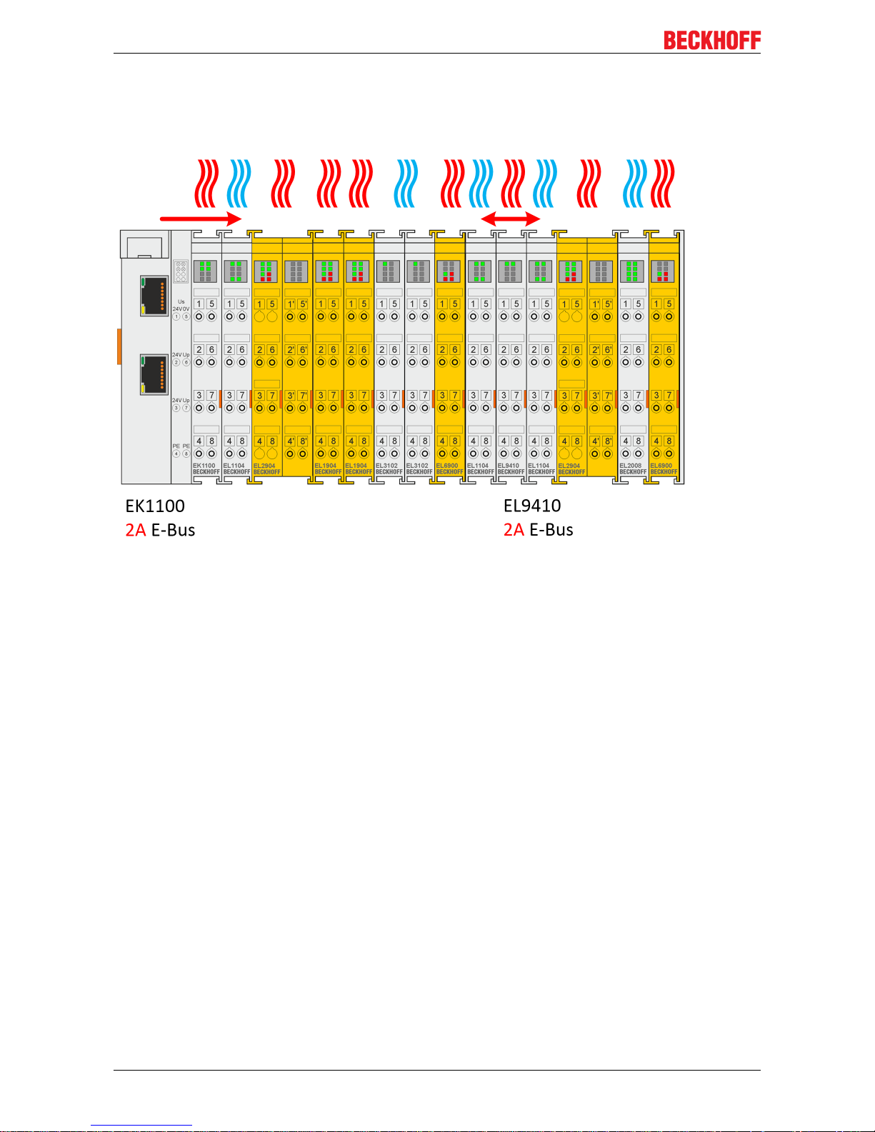
Thermally unfavorable arrangement of the TwinSAFE terminals
The following structure is rather unfavorable, since terminals with rather high waste heat are connected
directly to couplers or power supply terminals with high E-Bus load. The additional external heating of the
TwinSAFE terminals by the adjacent power supply units increases the internal terminal temperature, which
can lead to the maximum permissible temperature being exceeded. This leads to a diagnosis message
"overtemperature”.
Fig.9: Thermally unfavorable arrangement of the TwinSAFE terminals
Page 26
Operation
EL191826 Version: 1.2.0
Thermally favorable arrangement of the TwinSAFE terminals
The following structure is thermally favorable, since between the coupler / power supply terminal and
terminals with rather high waste heat, terminals with low current consumption and thus rather low waste heat
are placed.
Fig.10: Thermally favorable arrangement of the TwinSAFE terminals
Page 27

Operation
EL1918 27Version: 1.2.0
4.2.3.6 Installation on mounting rails
WARNING
Risk of electric shock and damage of device!
Bring the bus terminal system into a safe, powered down state before starting installation, disassembly or
wiring of the Bus Terminals!
Mounting
Fig.11: Installation on the mounting rail
The Bus Couplers and Bus Terminals are attached to commercially available 35mm mounting rails (DIN rail
according to EN60715) by applying slight pressure:
1. First attach the Fieldbus Coupler to the mounting rail.
2. The Bus Terminals are now attached on the right-hand side of the Fieldbus Coupler. Join the components with slot and key and push the terminals against the mounting rail, until the lock clicks onto the
mounting rail.
If the terminals are clipped onto the mounting rail first and then pushed together without slot and key,
the connection will not be operational! When correctly assembled, no significant gap should be visible
between the housings.
Fastening of mounting rails
The locking mechanism of the terminals and couplers protrudes into the profile of the mounting rail.
When installing the components, make sure that the locking mechanism doesn't come into conflict
with the fixing bolts of the mounting rail. For fastening mounting rails with a height of 7.5mm under
the terminals and couplers, use flat fastening components such as countersunk head screws or
blind rivets.
Page 28

Operation
EL191828 Version: 1.2.0
Disassembly
Fig.12: Removal from mounting rail
Each terminal is secured by a lock on the mounting rail, which must be released for disassembly:
1. Pull down the terminal at its orange-colored straps from the mounting rail by approx. 1 cm. The rail
locking of this terminal is automatically released, and you can now pull the terminal out of the Bus Terminal block with little effort.
2. To do this, grasp the unlocked terminal simultaneously at the top and bottom of the housing surfaces
with your thumb and index finger and pull it out of the Bus Terminal block.
4.2.4 Electrical installation
4.2.4.1 Connections within a Bus Terminal block
The electric connections between the Bus Coupler and the Bus Terminals are automatically realized by
joining the components:
Spring contacts (E-bus)
The six spring contacts of the E-bus deal with the transfer of the data and the supply of the Bus Terminal
electronics.
NOTE
Observe the E-bus current
Observe the maximum current that your Bus Coupler can supply to the E-bus! Use the EL9410 Power Supply Terminal if the current consumption of your terminals exceeds the maximum current that your Bus Coupler can feed to the E-bus supply.
Power contacts
The power contacts deal with the supply for the field electronics and thus represent a supply rail within the
Bus Terminal block. The power contacts are supplied via terminals on the Bus Coupler.
Note the connection of the power contacts
During the design of a Bus Terminal block, the pin assignment of the individual Bus Terminals must
be taken account of, since some types (e.g. analog Bus Terminals or digital 4-channel Bus Terminals) do not or not fully loop through the power contacts.
Potential supply terminals (EL91xx, EL92xx) interrupt the power contacts and thus represent the
start of a new supply rail.
Page 29

Operation
EL1918 29Version: 1.2.0
PE power contact
The power contact labelled PE can be used as a protective earth. For safety reasons this contact mates first
when plugging together, and can ground short-circuit currents of up to 125A.
Fig.13: PE power contact
CAUTION
Insulation tests
Note that, for reasons of electromagnetic compatibility, the PE contacts are capacitatively coupled to the
mounting rail. This may lead to incorrect results during insulation testing or to damage on the terminal (e.g.
disruptive discharge to the PE line during insulation testing of a consumer with a rated voltage of 230V).
For insulation testing, disconnect the PE supply line at the Bus Coupler or the Potential Supply Terminal! In
order to decouple further feed points for testing, these Power Feed Terminals can be released and pulled at
least 10mm from the group of terminals.
DANGER
Serious risk of injury!
The PE power contact must not be used for other potentials!
4.2.4.2 Overvoltage protection
If protection against overvoltage is necessary in your plant, provide a surge filter for the voltage supply to the
Bus Terminal blocks and the TwinSAFE terminals.
Page 30

Operation
EL191830 Version: 1.2.0
4.2.4.3 HD housing wiring
Fig.14: Connection of a cable to a terminal point
Up to 16 terminal points enable the connection of solid or finely stranded wires to the EtherCAT Terminal.
The terminal points are spring-loaded.
Several conductors at one connection
If it is necessary to connect several conductors to one connection, pre-connect them with terminal
blocks, for example.
Solid and stranded wire conductors with ferrules can be inserted directly into the terminal point. This
eliminates steps 1 and 3 in the above illustration. For all other conductor types, the terminal point must be
opened with a screwdriver to establish the connection.
Connect the cables as follows:
1. Open a terminal point by pushing a screwdriver straight into the
square opening above the terminal point as far as it will go. Do not turn or move the screwdriver back
and forth (do not lever)
2. The wire can now be inserted into the round terminal opening without any force.
3. The terminal closes automatically when the pressure is released, holding the wire safely and permanently.
The permissible conductor cross-sections can be taken from the following table.
Wire cross-section (solid) 0.08 ... 1.5mm
2
Wire cross-section (stranded wire) 0.25 ... 1.5mm
2
Wire cross-section (core wire with ferrule) 0.14 ... 0.75mm
2
Strip length 8 ... 9mm
Page 31

Operation
EL1918 31Version: 1.2.0
4.2.4.4 Connection of the EL1918
Fig.15: EL1918 connection
Terminal point Input Signal
1 1 Input 1+ (clock output)
2 Input 1- (safe input)
3 3 Input 3+ (clock output)
4 Input 3- (safe input)
5 5 Input 5+ (clock output)
6 Input 5- (safe input)
7 7 Input 7+ (clock output)
8 Input 7- (safe input)
9 2 Input 2+ (clock output)
10 Input 2- (safe input)
11 4 Input 4+ (clock output)
12 Input 4- (safe input)
13 6 Input 6+ (clock output)
14 Input 6- (safe input)
15 8 Input 8+ (clock output)
16 Input 8- (safe input)
Configurable inputs
The inputs 1 to 8 can be occupied as you want with normally closed contacts or normally open contacts. The corresponding analysis is carried out in the safety PLC. The input labeled Input x- is used
for connecting OSSD sensors (self-testing sensors).
Page 32
Operation
EL191832 Version: 1.2.0
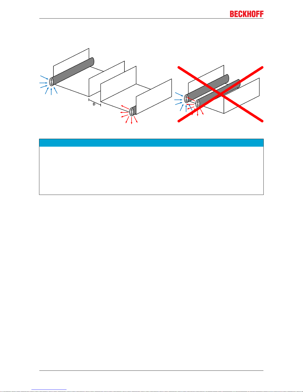
4.2.4.5 Signal cables
Cable routing
Fig.16: Cable routing
NOTE
Route the signal cable separately
The signal cable must be routed separately from potential sources of interference, such as motor supply cables, 230 VAC power cables etc.!
Interference caused by cables routed in parallel can influence the signal form of the test pulses and thus
cause diagnostic messages (e.g. sensor errors or OpenLoad errors).
D: Distance between the cable ducts should be as large as possible
blue arrows: signal line
red arrows: potential source of interference
The common routing of signals together with other clocked signals in a common cable also reduces the
maximum propagation, since crosstalk of the signals can occur over long cable lengths and cause diagnostic
messages.
Page 33

Operation
EL1918 33Version: 1.2.0
4.3 Configuration of the terminal in TwinCAT
CAUTION
Do not change CoE objects!
Do not change any of the CoE objects in the TwinSAFE terminals. Any modifications (e.g. via TwinCAT) of
the CoE objects will permanently set the terminals to the Fail-Stop state or lead to unexpected behavior of
the terminals!
4.3.1 Inserting a Bus Coupler
See TwinCAT automation software documentation.
4.3.2 Inserting a Bus Terminal
See TwinCAT automation software documentation.
4.3.3 Adding an EL1918
An EL1918 is added in exactly the same way as any other Beckhoff EtherCAT Terminal. Open TwinSAFE
Terminals item in the list and select the EL1918.
Fig.17: Adding an EL1918
Page 34

Operation
EL191834 Version: 1.2.0
4.3.4 Address settings on TwinSAFE terminals with 1023 possible
addresses
Fig.18: Address settings on TwinSAFE terminals with 1023 possible addresses
The TwinSAFE address of the terminal is set via the 10-way DIP switch on the left-hand side of the
TwinSAFE terminal. TwinSAFE addresses between 1 and 1023 are available.
DIP switch Address
1 2 3 4 5 6 7 8 9 10
ON OFF OFF OFF OFF OFF OFF OFF OFF OFF 1
OFF ON OFF OFF OFF OFF OFF OFF OFF OFF 2
ON ON OFF OFF OFF OFF OFF OFF OFF OFF 3
OFF OFF ON OFF OFF OFF OFF OFF OFF OFF 4
ON OFF ON OFF OFF OFF OFF OFF OFF OFF 5
OFF ON ON OFF OFF OFF OFF OFF OFF OFF 6
ON ON ON OFF OFF OFF OFF OFF OFF OFF 7
... ... ... ... ... ... ... ... ... ... ...
ON ON ON ON ON ON ON ON ON ON 1023
WARNING
TwinSAFE address
Each TwinSAFE address may only be used once within a network/ a configuration!
The address 0 is not a valid TwinSAFE address!
Page 35

Operation
EL1918 35Version: 1.2.0
4.3.5 Alias devices
The communication between the safety logic and the I/O level is realized via an alias level. At this alias level
(subnode Alias Devices) corresponding alias devices are created for all safe inputs and outputs, and also for
standard signal types. For the safe inputs and outputs, this can be done automatically via the I/O
configuration.
The connection- and device-specific parameters are set via the alias devices.
Fig.19: Starting the automatic import from the I/O configuration
If the automatic import is started from the I/O configuration, a selection dialog opens, in which the individual
terminals to be imported can be selected.
Fig.20: Selection from the I/O tree
The alias devices are created in the safety project when the dialog is closed via OK.
Alternatively, the user can create the alias devices individually. To this end select Add and New item from
the context menu, followed by the required device.
Page 36

Operation
EL191836 Version: 1.2.0
Fig.21: Creating alias devices by the user
4.3.6 EL1918 parameters in TwinCAT
After creating the alias device, it can be parameterized according to the user specifications.
The FSoE address is set under the Linking tab, and the link to the physical device is created.
Fig.22: Linking tab of the alias device
Under the Connection tab you can make further settings, e.g. the mapping of the info data or the behavior in
case of a module error.
Page 37

Operation
EL1918 37Version: 1.2.0
Fig.23: Connection tab of the alias device
The Safety Parameters tab contains the parameters of the EL1918 to be set. The parameters are set
separately for each input. Objects 0x8000 and 0x8001 are available for input 1. For all other inputs, the CoE
index is increased by 10hex each, so that objects 0x8070 and 0x8071 are available for input 8.
Fig.24: EL1918 parameters
Page 38

Operation
EL191838 Version: 1.2.0
Index Name Default value/
unit
Description
80x0:01 ModuloDiagTestPulse 0x00 / integer Modulo value for the frequency of
generating a test pulse.
0 -> every time
1 -> every second time
...
80x0:02 MultiplierDiagTestPulse 0x01 / integer Length of the test pulse in multiples of
400µs
80x0:04 Diag TestPulse active TRUE / Boolean Activation of test pulses for the
corresponding input module
80x0:05 Module Fault Link active TRUE / Boolean If a module error occurs in this module, a
module error is also set for all other
modules of this TwinSAFE component for
which this parameter is also set to TRUE.
80x1:01 InputFilterTime 0x000A / 0.1ms Input filter of the safe input. Following this
time the internal input signal changes to
the applied signal state.
80x1:02 DiagTestPulseFilterTime 0x0002 / 0.1ms Input filter for the test pulse signal
4.3.7 Process image of the EL1918
The process image of the EL1918 consists of 7 bytes process data in the input and 6 bytes process data in
the output.
Fig.25: Process image of the EL1918
The assignment of the individual signals in the safe data is listed in the following table.
Page 39

Operation
EL1918 39Version: 1.2.0
Name Process
image
Bit position Description
FSIN Module1.Input IN 0.0 Safe input 1
FSIN Module1.Module Fault IN 0.1 Module error information for input 1
FSIN Module2.Input IN 0.2 Safe input 2
FSIN Module2.Module Fault IN 0.3 Module error information for input 2
FSIN Module3.Input IN 0.4 Safe input 3
FSIN Module3.Module Fault IN 0.5 Module error information for input 3
FSIN Module4.Input IN 0.6 Safe input 4
FSIN Module4.Module Fault IN 0.7 Module error information for input 4
FSIN Module5.Input IN 1.0 Safe input 5
FSIN Module5.Module Fault IN 1.1 Module error information for input 5
FSIN Module6.Input IN 1.2 Safe input 6
FSIN Module6.Module Fault IN 1.3 Module error information for input 6
FSIN Module7.Input IN 1.4 Safe input 7
FSIN Module7.Module Fault IN 1.5 Module error information for input 7
FSIN Module8.Input IN 1.6 Safe input 8
FSIN Module8.Module Fault IN 1.7 Module error information for input 8
FSIN Module 1.ErrAck OUT 0.0 Error acknowledge for safe input 1
FSIN Module 2.ErrAck OUT 0.1 Error acknowledge for safe input 2
FSIN Module 3.ErrAck OUT 0.2 Error acknowledge for safe input 3
FSIN Module 4.ErrAck OUT 0.3 Error acknowledge for safe input 4
FSIN Module 5.ErrAck OUT 0.4 Error acknowledge for safe input 5
FSIN Module 6.ErrAck OUT 0.5 Error acknowledge for safe input 6
FSIN Module 7.ErrAck OUT 0.6 Error acknowledge for safe input 7
FSIN Module 8.ErrAck OUT 0.7 Error acknowledge for safe input 8
4.3.8 Local logic function
In addition to its standard function as a digital safe input terminal, the EL1918 TwinSAFE Terminal also
supports the option of executing a local safety-related user program. To do this, select the EL1918 as the
target system in the TwinCAT Safety Editor.
Information on creating a safety user program can be found in the documentation for the EL6910 (see
References [}8]).
The default project, so that the EL1918 once again behaves as a safe input terminal, can be reactivated by
deleting the safety-related user program from the TwinSAFE component. To do this, select the entry Safe
Logic, Mapping and Parameter Data in the dialog for deleting the project. After switching the TwinSAFE
component off and on, the default project is active again.
Fig.26: Deleting the project data
Page 40

Operation
EL191840 Version: 1.2.0
4.3.9 Project design limits of EL1918
Project design limits
The maximum project design size for EL1918 is determined by the available memory. This is managed dynamically. The values specified in the following table are therefore only guide values and
may differ from the actual values, depending on the safety project.
NOTE
Execution time of the logic function
The execution time of the logic program - with identical logic program - will typically be longer compared to
the EL6910, since the safe I/O signals must be processed additionally. This also has a corresponding effect
on the processing of the I/O signals, since with increasing project size these can only be evaluated with a
lower frequency.
Process image size max. 1486byte per data direction
(maximum memory size 0x1E00 for 3 buffers, ie with the same size of
input and output process data, a maximum size of 1280 bytes per data
direction is possible. Only straight start addresses are possible, so fill
bytes must be taken into account)
TwinSAFE connections 128 max.
(up to 255 CRCs in total; 1 CRC is required for a TwinSAFE connection
with 1 or 2 byte safe data.)
Safe data per TwinSAFE
connection
maximum 126byte (telegram length 255byte)
TwinSAFE blocks maximum 512 (when using ESTOP function blocks with complete input
and output mapping, other function blocks can lead to a smaller
maximum number)
TwinSAFE groups 128 max.
TwinSAFE user 40 max.
Standard PLC inputs dynamic (memory-dependent), max. 1484byte
Standard PLC outputs dynamic (memory-dependent), max. 1484byte
NOTE
Project development
TwinCAT 3.1 Build 4022.25 or newer is required to use the internal logic functions. If the EL1918 is used as
TwinSAFE slave with the default project, at least an EL6910, EK1960 or newer logic component is required
as TwinSAFE master.
4.4 TwinSAFE reaction times
The TwinSAFE terminals form a modular safety system that exchanges safety-oriented data via the Safetyover-EtherCAT protocol. This chapter is intended to help you determine the system's reaction time from the
change of signal at the sensor to the reaction at the actuator.
Typical reaction time
The typical reaction time is the time that is required to transmit information from the sensor to the actuator, if
the overall system is working without error in normal operation.
Page 41

Operation
EL1918 41Version: 1.2.0
Fig.27: Typical reaction time
Definition Description
RTSensor Reaction time of the sensor until the signal is provided at the interface. Typically supplied by
the sensor manufacturer.
RTInput Reaction time of the safe input, such as EL1904 or EP1908. This time can be found in the
technical data. In the case of the EL1904 it is 4 ms.
RTComm Reaction time of the communication This is typically 3x the EtherCAT cycle time, because
new data can only be sent in a new Safety-over-EtherCAT telegram. These times depend
directly on the higher-level standard controller (cycle time of the PLC/NC).
RTLogic Reaction time of the logic terminal. This is the cycle time of the logic terminal and typically
ranges from 500 µs to 10 ms for the EL6900, depending on the size of the safety project.
The actual cycle time can be read from the terminal.
RTOutput Reaction time of the output terminal. This typically lies within the range of 2 to 3 ms.
RTActor Reaction time of the actuator. This information is typically supplied by the actuator
manufacturer
WDComm Watchdog time of the communication
This results in the following equation for the typical reaction time:
with, for example
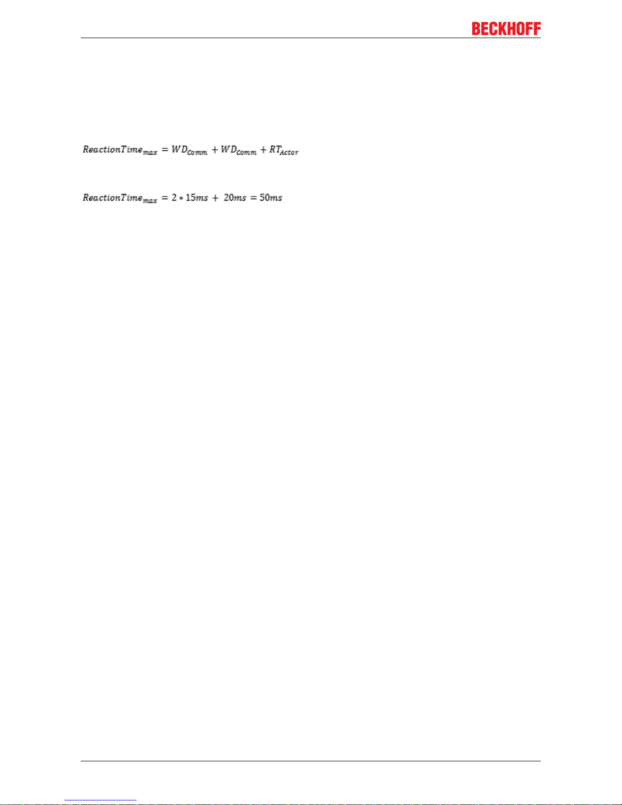
Worst-case reaction time
The worst case reaction time is the maximum time required to switch off the actuator in the case of an error.
Fig.28: Worst-case reaction time
Page 42
Operation
EL191842 Version: 1.2.0
This assumes that a signal change occurs at the sensor and is transmitted to the input. A communication
error occurs at precisely the moment when the signal is to be transferred to the communication interface.
This is detected by the logic following the watchdog time of the communication link. This information should
then be transferred to the output, but a further communication error occurs here. This error is detected at the
output following the expiry of the watchdog time and leads to the switch-off.
This results in the following equation for the worst-case reaction:
with, for example
Page 43

Operation
EL1918 43Version: 1.2.0
4.5 Diagnosis
4.5.1 Status LEDs
Fig.29: Status LEDs
LED Color Description
Input 1 green Status display for the respective input
LED lights up: Input is set
LED not lit: Input is not set
Input 2
Input 3
Input 4
Input 5
Input 6
Input 7
Input 8
4.5.2 Diagnostic LEDs
Diagnostic LEDs
LED lit flashing off
Diag 1
(green)
Environment variables,
operating voltage and internal
tests are in the valid range
• If Diag2 flashes, a logic
error code applies
- Environment variables,
operating voltage and internal
tests are outside the valid
range
• If Diag2 flashes, an
environment error code
applies
Diag 2
(red)
Together with Diag 3 and 4:
Global shutdown1) has
occurred. (see diag history of
the TwinSAFE components)
Logic or environment error
code according to Diag1 and
tables below is output
Together with Diag 3 and 4:
Global fault1) has occurred. (see
diag history of the TwinSAFE
components)
Diag 3
(red)
Global fault or global shutdown
on µC1
1)
- No global fault or global
shutdown on µC1
1)
Diag 4
(red)
Global fault or global shutdown
on µC2
1)
- No global fault or global
shutdown on µC2
1)
Page 44

Operation
EL191844 Version: 1.2.0
1. A global fault permanently disables the TwinSAFE component, so that it has to be replaced. A global
shutdown temporarily disables the TwinSAFE component. The error can be reset by switching off and
back on again.
Logic error codes of LED Diag2 (if LED Diag1 is lit)
Flashing
Code
Description
1 Function block error in one of the TwinSAFE groups
2 Communication error in one of the TwinSAFE groups
3 Error combination: Function block and communication
4 General error in one of the TwinSAFE groups
5 Error combination: General and function block
6 Error combination: General and communication
7 Error combination: General, function block and communication
Environment error codes of LED Diag2 (if LED Diag1 is off)
Flashing
Code
Description
1 Maximum supply voltage µC1 exceeded
2 Supply voltage µC1 below minimum value
3 Maximum supply voltage µC2 exceeded
4 Supply voltage µC2 below minimum value
5 Maximum internal temperature exceeded
6 Internal temperature below minimum value
7 Valid temperature difference between µC1 and µC2 exceeded
8 not used
9 not used
10 General error
4.5.3 Flash code display
LED Display Description
flashing 400ms ON / 400ms OFF
1 second pause between the flash codes
flickering 50ms ON / 50ms OFF
4.5.4 Diagnosis History
The diagnostic history of the TwinSAFE devices that support this function is implemented in accordance with
the ETG guideline ETG.1020 Chapter 13 "Diagnosis Handling". The diagnostic messages are saved by the
TwinSAFE device in a dedicated CoE object under 0x10F3 and can be read out by the application or by
TwinCAT.
Both the control entries and the history itself can be found in the CoE object 0x10F3. The entry Newest
Message (0x10F3:02) contains the subindex of 0x10F3, which contains the latest diagnostic message, e.g.
0x06 for diagnostic message 1.
Page 45

Operation
EL1918 45Version: 1.2.0
Index 10F3
hex
Diagnosis History
Index (hex) Name Meaning Data type Flags Default
10F3:0 Diagnosis
History
10F3:01 Maximum
Messages
Maximum number of stored messages. A
maximum of 64 messages can be stored.
After that the respective oldest messages
are overwritten.
UINT8 RO 0x40 (64
dec
)
10F3:02 Newest
Message
Subindex of the latest message UINT8 RO 0x00 (0
dec
)
10F3:03 Newest
Acknowledged
Message
Subindex of the last confirmed message UINT8 RW 0x00 (0
dec
)
10F3:04 New
Messages
Available
Indicates that a new message is available BOOLEAN RO 0x00 (0
dec
)
10F3:05 Flags Set via the startup list. If set to 0x0001, the
diagnostic messages are additionally sent
by emergency to the EtherCAT master
UINT16 RW 0x0000 (0
dec
)
10F3:06 Diagnosis
Message 001
Diagnostic message 1 BYTE[32] RO {0}
... ... ... ... ... ...
10F3:45 Diagnosis
Message 064
Diagnostic message 64 BYTE[32] RO {0}
Structure of the diagnostic messages
• DiagCode (4 bytes) – in this case always 0x 0000 E000
• Flags (2 bytes) - diagnosis type (info, warning or error), timestamp and number of parameters
contained (see the following table)
• Text ID (2 bytes) – ID of the diagnostic message as a reference to the message text from the ESI/XML
• Timestamp (8 bytes) – local slave time in ns since switching on the TwinSAFE device
• dynamic parameters (16 bytes) – parameters that can be inserted in the message text (see following
table)
Flags in diagnostic messages
Data type Offset Description
UINT16 Bits 0 to 3 DiagType (value)
0 Info message
1 Warning message
2 Error message
3…15 reserved
Bit 4 If the bit = 1, the timestamp contained in the message is the local timestamp of the
TwinSAFE device. The age of the diagnostic message can be deduced by
calculation with the current timestamp from the CoE object 0x10F8.
Bits 5 to 7 reserved
Bits 8 to 15 Number of parameters in this diagnostic message
Page 46
Operation
EL191846 Version: 1.2.0
Dynamic parameters in the diagnostic messages
Type Data type Description
Flags parameter 1 UINT16 Describes the type of parameter 1
Bits 12 to 15 =0Bits 0 to 11 = data type of parameter 1
0x0001 - BOOLEAN
0x0002 - INT8
0x0003 - INT16
0x0004 - INT32
0x0005 - UINT8
0x0006 - UINT16
0x0007 - UINT32
0x0008 - REAL32
0x0011 - REAL64
0x0015 - INT64
0x001B - UINT64
Text parameters and formats are
specified in ETG.2000.
Parameter 1 Data type in accordance with
flags
Value of parameter 1
Flags parameter 2 UINT16 see Flags parameter 1
Parameter 2 Data type in accordance with
flags
Value of parameter 2
...
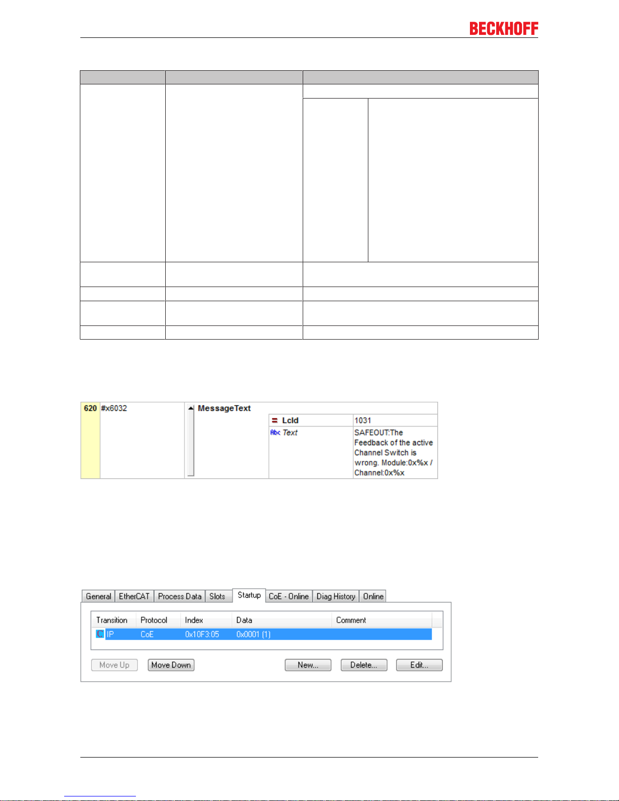
The diagnostic messages are saved in text form in the ESI/XML file belonging to the TwinSAFE device. On
the basis of the Text ID contained in the diagnostic message, the corresponding plain text message can be
found in the respective languages. The parameters can be inserted in the appropriate positions. In the
following example, %x is used for a hexadecimal representation of the parameters.
Fig.30: ESI/XML message text
Via the entry New Messages Available the user receives information that new messages are available. The
messages can be read out via CompleteAccess (a CoE read command for the complete CoE object
0x10F3). The New Messages Available bit is reset after reading the messages.
The sending of emergency messages to the EtherCAT master is activated by adding the CoE object
0x10F3:05 to the startup list (Transition IP, value 0x0001). If new diagnostic messages arrive, they are
entered in object 0x10F3 and additionally sent by emergency to the EtherCAT master.
Fig.31: Startup list
Page 47
Operation
EL1918 47Version: 1.2.0
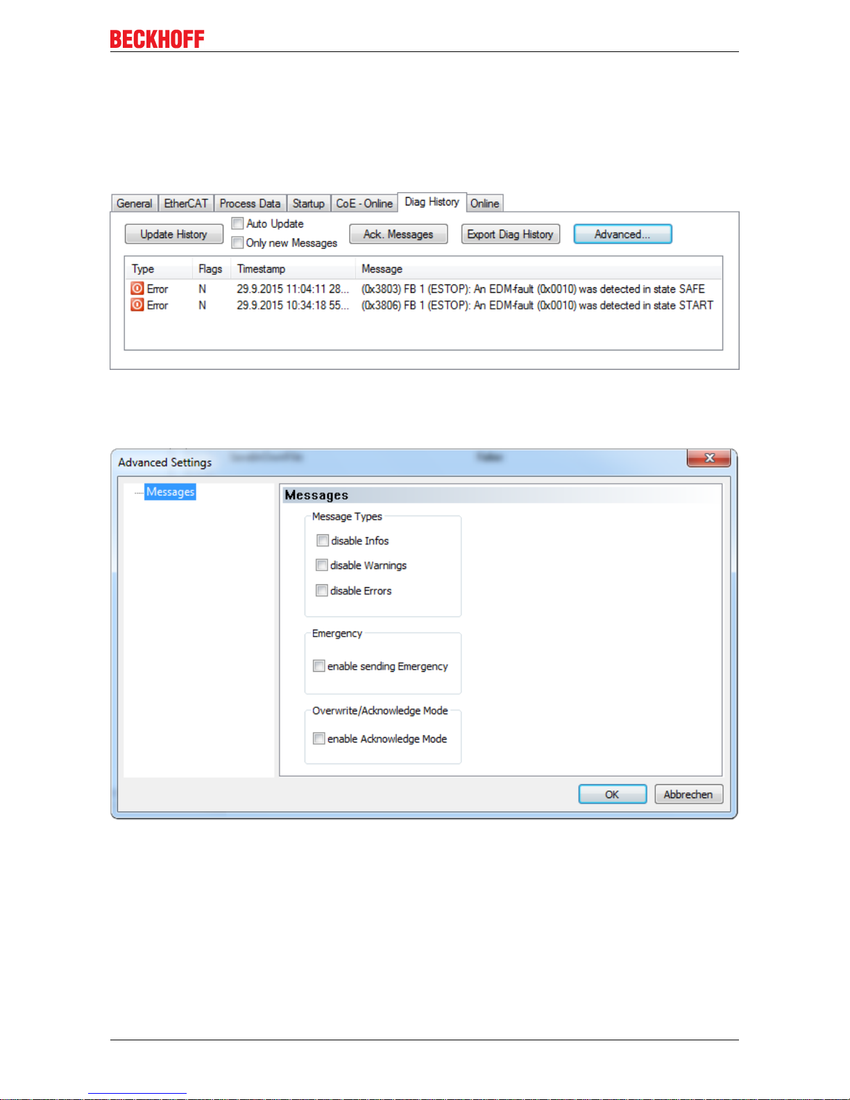
4.5.5 Diag History tab
All errors occurring within the TwinSAFE components are stored in their diag history. The diag history can be
viewed by selecting the corresponding TwinSAFE component in the I/O tree structure and then selecting the
Diag History tab. Use the Update History button to fetch the current data from the TwinSAFE component.
Errors within the logic, the function blocks, the connections or the component itself are stored with a
corresponding time stamp.
Fig.32: Diag history
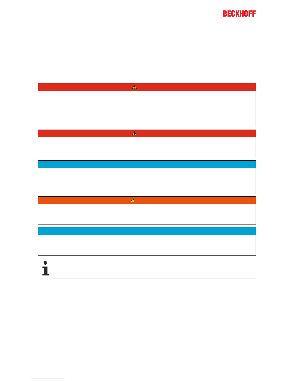
Use the Advanced… button to open the advanced settings. Here, the user can customize the behavior of the
diag history.
Fig.33: Diag history – advanced settings
Page 48

Operation
EL191848 Version: 1.2.0
Advanced Settings
Setting Description
Message Types • disable Info
Messages with status Info are not stored in the diag history
• disable Warnings
Messages with status Warning are not stored in the diag history
• disable Errors
Messages with status Error are not stored in the diag history
Emergency In addition to saving the message in the diag history, an emergency object
is also sent and displayed in the TwinCAT logger window.
Overwrite/Acknowledge Mode This setting is currently not supported.
4.6 Maintenance
Maintenance
The TwinSAFE components are maintenance-free!
Environmental conditions
WARNING
Observe the specified environmental conditions!
Please ensure that the TwinSAFE components are only stored and operated under the specified conditions
(see technical data).
If the TwinSAFE component is operated outside the permitted temperature range it will switch to Global
Shutdown state.
Cleaning
Protect the TwinSAFE component from unacceptable soling during operation and storage!
If the TwinSAFE component was subjected to unacceptable soiling it may no longer be operated!
WARNING
Have soiled terminals checked!
Cleaning of the TwinSAFE component by the user is not permitted!
Please send soiled terminals to the manufacturer for inspection and cleaning!
Page 49

Operation
EL1918 49Version: 1.2.0
4.7 Service life
The TwinSAFE terminals are designed for a service life of 20 years.
Due to the high diagnostic coverage within the lifecycle no special proof tests are required.
The TwinSAFE terminals bear a date code, which is composed as follows:
Datecode: CWYYSWHW
Legend:
CW: Calendar week of manufacture
YY: Year of manufacture
SW: Software version
HW: Hardware version
Sample: DateCode 17110500
Calendar week: 17
Year: 2011
Software version: 05
Hardware version: 00
In addition the TwinSAFE terminals bear a unique serial number.
Fig.34: Unique serial number of a TwinSAFE terminal
4.8 Decommissioning
DANGER
Serious risk of injury!
Bring the bus system into a safe, de-energized state before starting disassembly of the devices!
Disposal
In order to dispose of the device, it must be removed and fully dismantled.
• Housing components (polycarbonate, polyamide (PA6.6)) are suitable for plastic recycling.
• Metal parts can be sent for metal recycling.
• Electronic parts such as disk drives and circuit boards must be disposed of in accordance with national
electronics scrap regulations.
Page 50
Operation
EL191850 Version: 1.2.0
4.9 Firmware update of TwinSAFE products
For TwinSAFE products there is the option of performing a firmware update via the EtherCAT interface. The
complete firmware of the TwinSAFE component is deleted and replaced by a new version.
The latest firmware can be downloaded from the Beckhoff website or requested from Beckhoff Support. The
versions are available in an encrypted form and can only be loaded onto the matching TwinSAFE product.
An incorrect firmware file is rejected by the respective TwinSAFE product.
Prerequisite for a firmware update
DANGER
Put the machine into a safe state!
A firmware update stops the current processing of the firmware of the TwinSAFE product. It is essential that
you switch the TwinSAFE system to the safe state before you start an update.
All safe outputs must be in a safe, de-energized state. If hanging or pulling loads are present on the machine or the TwinSAFE system, these must also be brought into a safe state through external safety measures if necessary.
DANGER
Monitor the machine state!
It is necessary that you have control over the machine, i.e. you can see it and thus ensure that it is in a safe
state and that a firmware update can be carried out without endangering the operators or other personnel.
NOTE
Avoid communication interruptions during the download
Please avoid disconnecting the EtherCAT connection while downloading the firmware under any circumstances. If a communication error does occur, the TwinSAFE product may subsequently be unusable and
must be sent to the Beckhoff Service.
WARNING
Default project for TwinSAFE I/O components with local logic function!
After a firmware update, any implemented default project starts automatically. An EK1960, for example,
would start up as a TwinSAFE I/O slave after a firmware update.
NOTE
Firmware update of TwinSAFE logics
If a firmware update is performed for a TwinSAFE logic component, e.g. on a TwinSAFE logic EL6910, the
safety-related user program must be reloaded to the TwinSAFE logic after the update.
EtherCAT communication
When an EtherCAT component is updated, it is switched to BOOTSTRAP mode. This can have an
effect on the EtherCAT communication with other EtherCAT devices.
Page 51
Operation
EL1918 51Version: 1.2.0
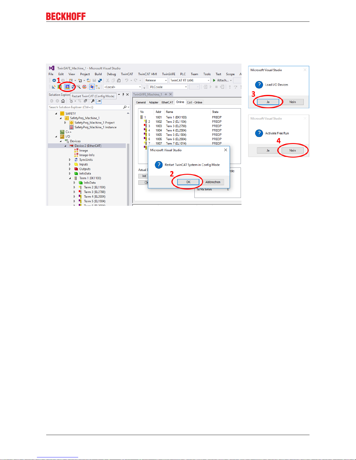
Performing the firmware update
Click the button (1) in the TwinCAT system to enter Config mode. Confirm the query with OK (2). After that a
further window appears which must be confirmed with Yes (Ja) (3). Deactivate the "Free Run" with No (Nein)
(4). The system is now in "Configuration mode".
Fig.35: Firmware update of TwinSAFE products - Part 1
Page 52
Operation
EL191852 Version: 1.2.0
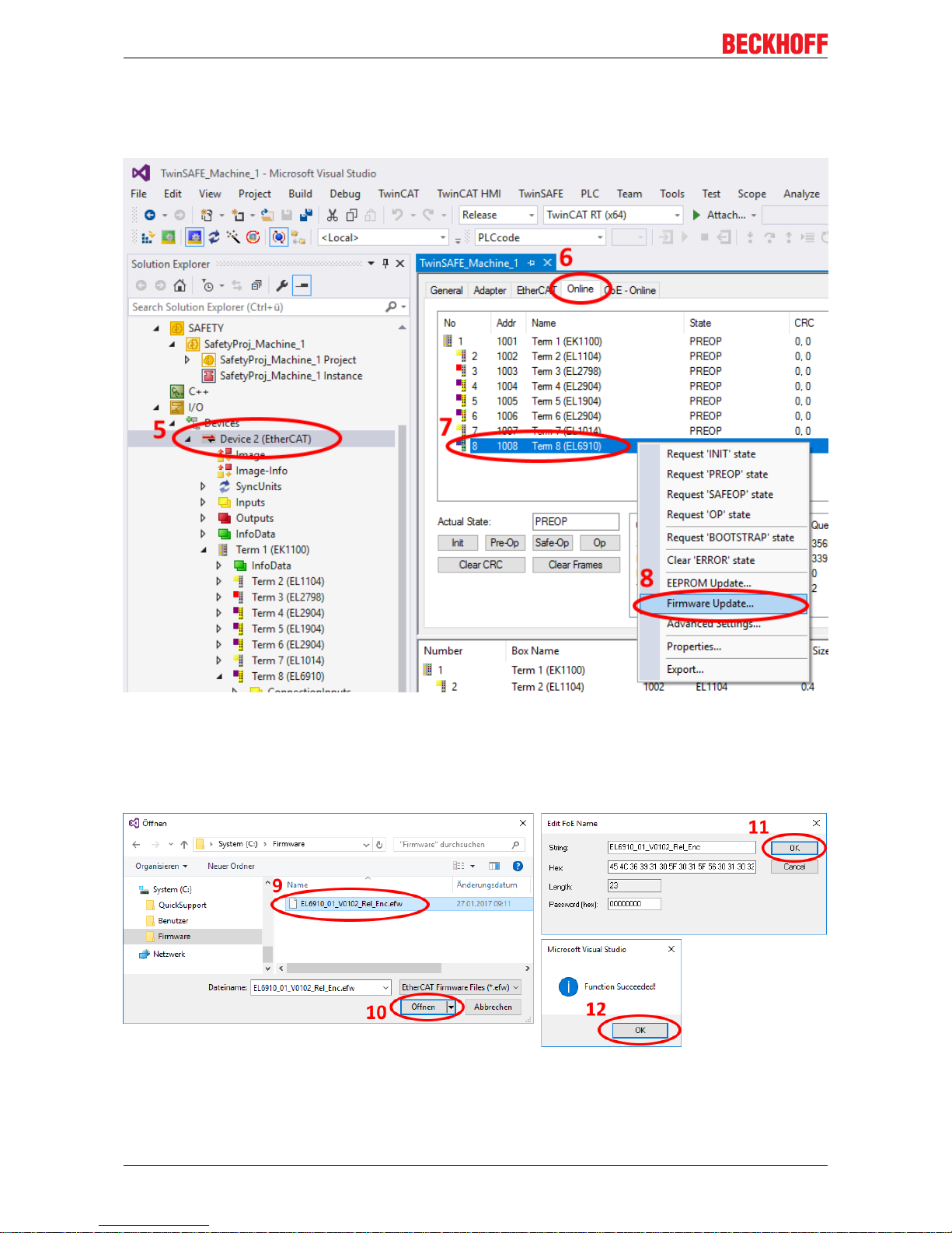
To perform the firmware update, select the "Online" tab (6) for the "EtherCAT Device" (5). If you want to
update several components, you can select the corresponding components (7) together; for individual
components, select only these. Subsequently, click with the right mouse button inside the selected area and
select the command "Firmware Update..." (8) in the command overview.
Fig.36: Firmware update of TwinSAFE products - Part 2
In the place where you have stored the desired firmware version, select the firmware file (9) and click
"Open" (10). Confirm the window that then opens with "OK" (11); the firmware update is then performed.
After successful completion you must click OK (12) in the concluding "Function Succeeded" window. You
can then switch the system back to Run mode and use the TwinSAFE system.
Fig.37: Firmware update of TwinSAFE products - Part 3
Page 53

Appendix
EL1918 53Version: 1.2.0
5 Appendix
5.1 Support and Service
Beckhoff and their partners around the world offer comprehensive support and service, making available fast
and competent assistance with all questions related to Beckhoff products and system solutions.
Beckhoff's branch offices and representatives
Please contact your Beckhoff branch office or representative for local support and service on Beckhoff
products!
The addresses of Beckhoff's branch offices and representatives round the world can be found on her internet
pages:
http://www.beckhoff.com
You will also find further documentation for Beckhoff components there.
Beckhoff Headquarters
Beckhoff Automation GmbH & Co. KG
Huelshorstweg 20
33415 Verl
Germany
Phone: +49(0)5246/963-0
Fax: +49(0)5246/963-198
e-mail: info@beckhoff.com
Beckhoff Support
Support offers you comprehensive technical assistance, helping you not only with the application of
individual Beckhoff products, but also with other, wide-ranging services:
• support
• design, programming and commissioning of complex automation systems
• and extensive training program for Beckhoff system components
Hotline: +49(0)5246/963-157
Fax: +49(0)5246/963-9157
e-mail: support@beckhoff.com
Beckhoff Service
The Beckhoff Service Center supports you in all matters of after-sales service:
• on-site service
• repair service
• spare parts service
• hotline service
Hotline: +49(0)5246/963-460
Fax: +49(0)5246/963-479
e-mail: service@beckhoff.com
Page 54

Appendix
EL191854 Version: 1.2.0
5.2 Certificates
Page 55

List of figures
EL1918 55Version: 1.2.0
List of figures
Fig. 1 Slot and key system and screwless (spring-loaded) connection system..................................... 9
Fig. 2 Bus Coupler (EtherCAT).............................................................................................................. 10
Fig. 3 Overview of EtherCAT Terminals ................................................................................................ 11
Fig. 4 EL1918 – TwinSAFE Terminal with 8 fail-safe inputs.................................................................. 14
Fig. 5 Characteristic curve of the inputs ................................................................................................ 19
Fig. 6 EL1918 dimensions ..................................................................................................................... 20
Fig. 7 Spring contacts of Beckhoff I/O components............................................................................... 22
Fig. 8 Installation position and minimum distances ............................................................................... 23
Fig. 9 Thermally unfavorable arrangement of the TwinSAFE terminals ................................................ 25
Fig. 10 Thermally favorable arrangement of the TwinSAFE terminals .................................................... 26
Fig. 11 Installation on the mounting rail................................................................................................... 27
Fig. 12 Removal from mounting rail......................................................................................................... 28
Fig. 13 PE power contact......................................................................................................................... 29
Fig. 14 Connection of a cable to a terminal point .................................................................................... 30
Fig. 15 EL1918 connection...................................................................................................................... 31
Fig. 16 Cable routing ............................................................................................................................... 32
Fig. 17 Adding an EL1918 ....................................................................................................................... 33
Fig. 18 Address settings on TwinSAFE terminals with 1023 possible addresses ................................... 34
Fig. 19 Starting the automatic import from the I/O configuration ............................................................. 35
Fig. 20 Selection from the I/O tree........................................................................................................... 35
Fig. 21 Creating alias devices by the user............................................................................................... 36
Fig. 22 Linking tab of the alias device...................................................................................................... 36
Fig. 23 Connection tab of the alias device............................................................................................... 37
Fig. 24 EL1918 parameters ..................................................................................................................... 37
Fig. 25 Process image of the EL1918...................................................................................................... 38
Fig. 26 Deleting the project data.............................................................................................................. 39
Fig. 27 Typical reaction time.................................................................................................................... 41
Fig. 28 Worst-case reaction time............................................................................................................. 41
Fig. 29 Status LEDs................................................................................................................................. 43
Fig. 30 ESI/XML message text ................................................................................................................ 46
Fig. 31 Startup list.................................................................................................................................... 46
Fig. 32 Diag history.................................................................................................................................. 47
Fig. 33 Diag history – advanced settings................................................................................................. 47
Fig. 34 Unique serial number of a TwinSAFE terminal............................................................................ 49
Fig. 35 Firmware update of TwinSAFE products - Part 1 ........................................................................ 51
Fig. 36 Firmware update of TwinSAFE products - Part 2 ........................................................................ 52
Fig. 37 Firmware update of TwinSAFE products - Part 3 ........................................................................ 52
 Loading...