

Page 1

Operating instructions for
EL1904
TwinSAFE input terminal with 4 fail-safe inputs
Version: 1.5.1
Date: 30.01.2015
Page 2

Page 3

Table of contents
Table of contents
1 Foreword 3
1.1 Notes on the manual 3
1.1.1 Disclaimer 3
1.1.2 Brands 3
1.1.3 Patents 3
1.1.4 Copyright 3
1.1.5 Delivery conditions 3
1.2 Safety instructions 4
1.2.1 Delivery state 4
1.2.2 Operator's obligation to exercise diligence 4
1.2.3 Description of safety symbols 5
1.2.4 Origin of the document 5
1.2.5 Documentation issue status 6
2 System description 7
2.1 The Beckhoff Bus Terminal system 7
2.1.1 Bus Coupler 8
2.1.2 Bus Terminals 9
2.1.3 E-bus 9
2.1.4 Power contacts 9
2.2 TwinSAFE 10
2.2.1 The I/O construction kit is extended safely 10
2.2.2 Safety concept 10
2.2.3 EL1904, EL2904 – Bus Terminals with 4 fail-safe inputs or outputs 11
2.2.4 EL6900 - TwinSAFE logic terminal 11
2.2.5 The fail-safe principle (Fail Stop) 11
3 Product description 12
3.1 General description 12
3.2 Intended use 13
3.3 Technical data 14
3.4 Safety parameters 15
3.5 Characteristic curve of the inputs 15
3.6 Dimensions 16
3.7 Block diagram EL1904 17
EL1904 1
Page 4

Table of contents
4 Operation 18
4.1 Installation 18
4.1.1 Safety instructions 18
4.1.2 Transport / storage 18
4.1.3 Mechanical installation 19
4.1.4 Electrical installation 22
4.1.5 Tested devices 27
4.2 Operation in potentially explosive atmospheres (ATEX) 28
4.2.1 Special conditions 28
4.2.2 Identification 29
4.2.3 Date code and serial number 29
4.2.4 Further ATEX documentation 29
4.3 Configuration of the EL1904 in the TwinCAT System Manager 30
4.3.1 Inserting a Beckhoff Bus Coupler 30
4.3.2 Inserting a Beckhoff Bus Terminal 30
4.3.3 Inserting an EL1904 30
4.3.4 Address settings on the TwinSAFE terminals 31
4.3.5 Entering a TwinSAFE address and parameters in the System Manager 32
4.4 Diagnostics 35
4.4.1 Diagnostic LEDs 35
4.4.2 Diagnostic objects 37
4.5 Maintenance 38
4.5.1 Cleaning 38
4.5.2 Service life 38
4.6 Decommissioning 39
4.6.1 Disposal 39
5 Appendix 40
5.1 Beckhoff Support and Service 40
5.1.1 Beckhoff branches and partner companies Beckhoff Support 40
5.1.2 Beckhoff company headquarters 40
5.2 Certificates 41
2 EL1904
Page 5

Foreword
1 Foreword
1.1 Notes on the manual
This description is only intended for the use of trained specialists in control and automation technology
familiar with the applicable national standards. It is essential that the following notes and explanations are
followed when installing and commissioning these components.
The responsible staff must ensure that the application or use of the products described satisfy all the
safety requirements, including all the relevant laws, regulations, guidelines and standards.
1.1.1 Disclaimer
This documentation has been prepared with care. The products described are, however, constantly under
development. For this reason, the documentation may not always have been fully checked for
consistency with the performance data, standards or other characteristics described.
If it should contain technical or editorial errors, we reserve the right to make changes at any time and
without notice.
No claims for the modification of products that have already been supplied may be made on the basis of
the data, diagrams and descriptions in this documentation.
1.1.2 Brands
Beckhoff®, TwinCAT®, EtherCAT®, Safety over EtherCAT®, TwinSAFE® and XFC® are registered
trademarks of and licensed by Beckhoff Automation GmbH.
The use by third parties of other brand names or trademarks contained in this documentation may lead to
an infringement of the rights of the respective trademark owner.
1.1.3 Patents
The EtherCAT technology is patent protected, in particular by the following applications and patents:
EP1590927, EP1789857, DE102004044764, DE102007017835 with the corresponding applications and
registrations in various other countries.
The TwinCAT technology is patent protected, in particular by the following applications and patents:
EP0851348, US6167425 with the corresponding applications and registrations in various other countries.
1.1.4 Copyright
©
Beckhoff Automation GmbH & Co. KG.
The copying, distribution and utilization of this document as well as the communication of its contents to
others without express authorization is prohibited. Offenders shall be held liable for damages. All rights
conferred by patent grant or registration of a utility model or registered design are reserved.
1.1.5 Delivery conditions
In addition, the general delivery conditions of the company Beckhoff Automation GmbH & Co. KG apply.
EL1904 3
Page 6

Foreword
1.2 Safety instructions
1.2.1 Delivery state
All the components are supplied in particular hardware and software configurations appropriate for the
application. Modifications to hardware or software configurations other than those described in the
documentation are not permitted, and nullify the liability of Beckhoff Automation GmbH & Co. KG.
1.2.2 Operator's obligation to exercise diligence
The operator must ensure that
the TwinSAFE products are only used as intended (see section Product description);
the TwinSAFE products are only operated in sound condition and in working order (see chapter
Cleaning).
the TwinSAFE products are operated only by suitably qualified and authorized personnel.
the personnel is instructed regularly about relevant occupational safety and environmental
protection aspects, and is familiar with the operating instructions and in particular the safety
instructions contained herein.
the operating instructions are in good condition and complete, and always available for reference
at the location where the TwinSAFE products are used.
none of the safety and warning notes attached to the TwinSAFE products are removed, and all
notes remain legible.
4 EL1904
Page 7
Foreword
1.2.3 Description of safety symbols
The following safety symbols are used in these operating instructions. They are intended to alert the
reader to the associated safety instructions.
Serious risk of injury!
DANGER
WARNING
CAUTION
Failure to follow the safety instructions associated with this symbol directly endangers
the life and health of persons.
Caution - Risk of injury!
Failure to follow the safety instructions associated with this symbol endangers the life
and health of persons.
Personal injuries!
Failure to follow the safety instructions associated with this symbol can lead to injuries
to persons.
Damage to the environment or devices
Attention
Failure to follow the instructions associated with this symbol can lead to damage to the
environment or equipment.
Tip or pointer
Note
This symbol indicates information that contributes to better understanding.
1.2.4 Origin of the document
These operating instructions were originally written in German. All other languages are derived from the
German original.
EL1904 5
Page 8

Foreword
1.2.5 Documentation issue status
Version Comment
1.5.1
1.5.0
1.4.0
1.3.1
1.3.0
1.2.1
1.2.0
1.1.0
1.0.0
Certificate updated
Company address amended
Safety parameters extended
Extended temperature range added
Temperature measurement described
Characteristic input curve added
Description of date code extended
Document origin added
Clock output currents in the technical data amended
Block diagram for EL1904 added
Reference to EN 60068-2-29 removed
ATEX notes amended
Installation position / minimum distances extended
Notes regarding overvoltage protection amended
Notes regarding cable length and clocked signals extended
Diagnostics for CoE object 0x800E described
Minor amendments for EtherCAT
Copyright / disclaimer modified
Support / service addresses updated
First released version
6 EL1904
Page 9
System description
2 System description
2.1 The Beckhoff Bus Terminal system
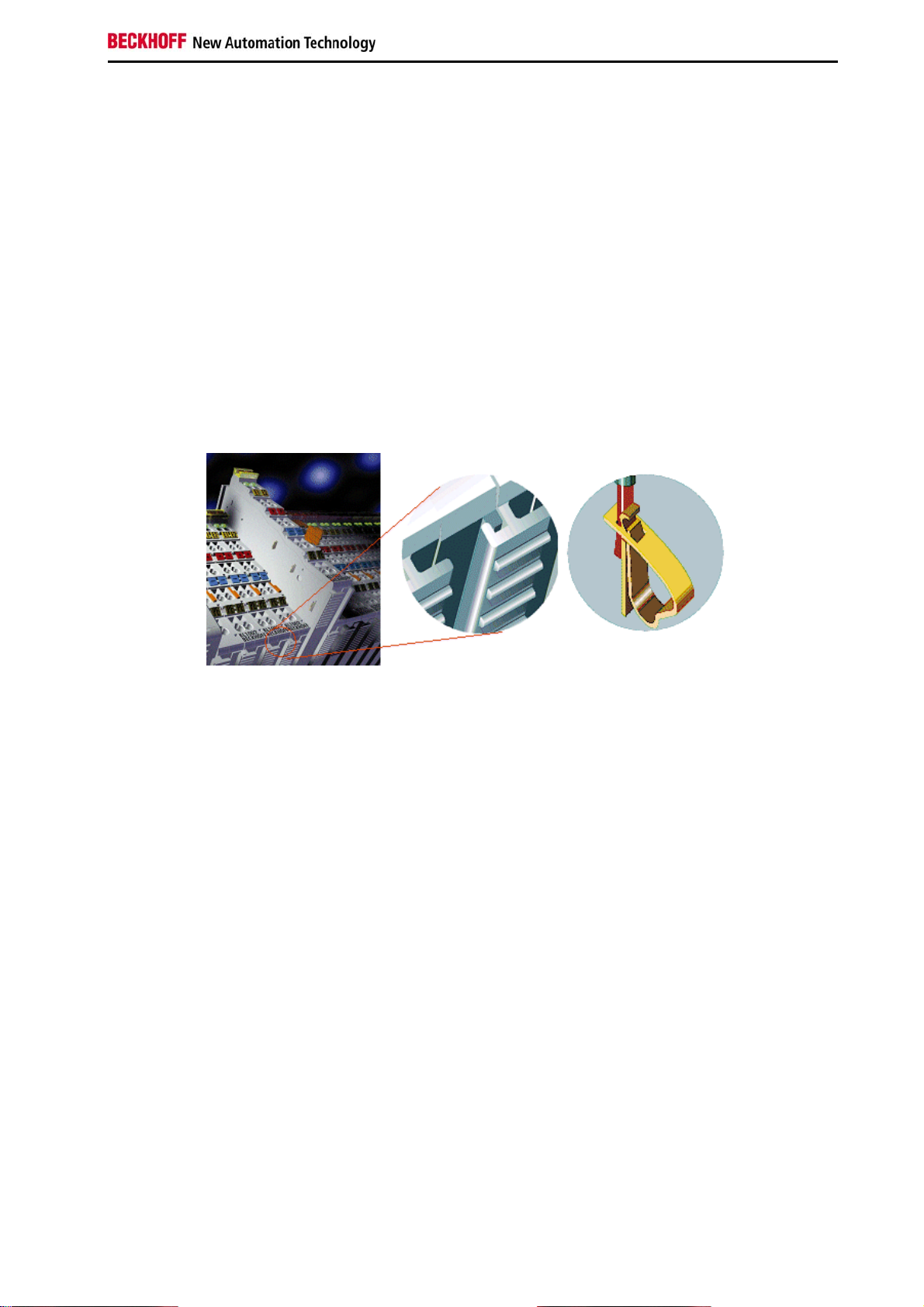
The Beckhoff Bus Terminal system is used for decentralized connection of sensors and actuators to a
control system. The Beckhoff Bus Terminal system components are mainly used in industrial automation
and building management applications. In its minimum configuration, a bus station consists of a Bus
Coupler or a Bus Terminal Controller and Bus Terminals connected to it. The Bus Coupler forms the
communication interface to the higher-level controller, and the terminals are the interface to sensors and
actuators. The whole bus station is clipped onto a 35 mm DIN mounting rail (EN 50022). The mechanical
cross connection of the bus station is established via a slot and key system at the Bus Coupler and the
Bus Terminals.
The sensors and actuators are connected with terminals via the screwless Cage Clamp
system.
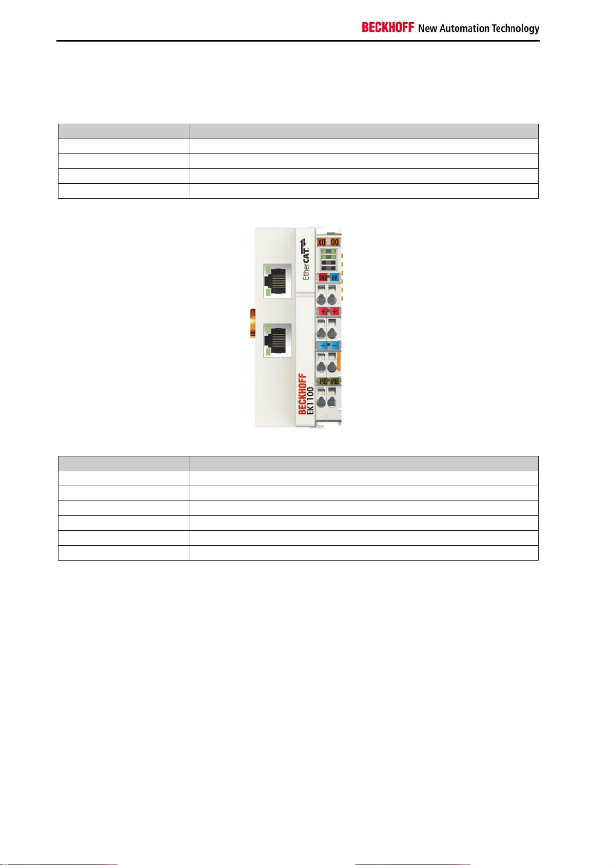
In order to accommodate the wide range of different communication standards encountered in industrial
automation, Beckhoff offers Bus Couplers for a number of common bus systems (e.g. EK1100 for
EtherCAT).
©
connection
EL1904 7
Page 10
System description
2.1.1 Bus Coupler
Mechanical data
Mechanical data Bus Coupler
Material polycarbonate, polyamide (PA6.6).
Dimensions (W x H x D) 44 mm x 100 mm x 68 mm
Installation on 35 mm mounting rail (EN50022) with locking
Attachable by
double slot and key connection
Connection technology
Connection technology Bus Coupler
Wiring Cage Clamp® spring-loaded system
Connection cross-section 0.08 mm2 ... 2.5 mm2, stranded wire, solid wire
Fieldbus connection depending on fieldbus
Power contacts 3 spring contacts
Current load 10 A
Rated voltage 24 VDC
8 EL1904
Page 11

System description
2.1.2 Bus Terminals
Mechanical data
Mechanical data Bus Terminal
Material polycarbonate, polyamide (PA6.6).
Dimensions (W x H x D) 12 mm x 100 mm x 68 mm or 24 mm x 100 mm x 68 mm
Installation on 35 mm mounting rail (EN50022) with locking
Attachable by double slot and key connection
Connection technology
Connection technology Bus Terminal
Wiring Cage Clamp® spring-loaded system
Connection cross-section 0.08 mm2 ... 2.5 mm2, stranded wire, solid wire
Fieldbus connection E-bus
Power contacts up to 3 blade/spring contacts
Current load 10 A
Rated voltage depends on Bus Terminal type
2.1.3 E-bus
The E-bus is the data path within a terminal strip. The E-bus is led through from the Bus Coupler through
all the terminals via six contacts on the terminals' side walls.
2.1.4 Power contacts
The operating voltage is passed on to following terminals via three power contacts. Terminal strip can be
split into galvanically isolated groups by means of potential feed terminals as required. The power feed
terminals play no part in the control of the terminals, and can be inserted at any locations within the
terminal strip.
EL1904 9
Page 12

System description
2.2 TwinSAFE
2.2.1 The I/O construction kit is extended safely
With the TwinSAFE Terminals, Beckhoff offers the option of simply expanding the proven Bus Terminal
system, and to transfer the complete cabling for the safety circuit into the already existing fieldbus cable.
Safe signals can be mixed with standard signals without restriction. This saves design effort, installation
and material. Maintenance is simplified significantly through faster diagnosis and simple replacement of
only a few components.
The new ELx9xx series Bus Terminals only include three basic functionalities: digital inputs EL19xx,
digital outputs EL29xx and a logic unit EL6900. For a large number of applications, all sensors and
actuators can be wired on these Bus Terminals. The required logical link of the inputs and the outputs is
handled by the EL6900. For small to medium-sized configurations, the tasks of a fail-safe PLC can thus
be handled within the Bus Terminal system.
2.2.2 Safety concept
TwinSAFE: Safety and I/O technology in one system
Extension of the familiar Beckhoff I/O system with TwinSAFE terminals
Freely selectable mix of safe and standard signals
Logical link of the I/Os in the EL6900 TwinSAFE logic terminal
Safety-relevant networking of machines via bus systems
TwinSAFE protocol (Fail Safe over EtherCAT - FSoE)
Transfer of safety-relevant data via any media (“genuine black channel”)
TwinSAFE communication via fieldbus systems such as EtherCAT, Lightbus, PROFIBUS or
Ethernet
IEC 61508:2010 SIL 3 compliant
Configuring instead of wiring: the TwinSAFE configurator
Configuration of the TwinSAFE system via the TwinCAT System Manager
System Manager for editing and displaying all bus parameters
Certified function blocks such as emergency stop, operation mode, etc.
Simple handling
Typical function blocks for machine safety
Any bus connection with the EL6900 TwinSAFE logic terminal
TwinSAFE logic Bus Terminal EL6900
Link unit between TwinSAFE input and output terminals
Configuration of a simple, flexible, cost-effective, decentralized safety controller
No safety requirements for higher-level control system
TwinSAFE enables networks with up to 65535 TwinSAFE devices
TwinSAFE logic terminal can establish up to 128 connections (TwinSAFE connections).
Several TwinSAFE logic terminals are cascadable in a network
Safety functions such as emergency stop, protective door etc. are already included
Suitable for applications up to SIL 3 according to IEC 61508:2010 and DIN EN ISO 13849-
1:2006 (Cat 4, PL e).
10 EL1904
Page 13

System description
TwinSAFE digital input (EL1904) and output terminal (EL2904)
All current safety sensors can be connected
Operation with a TwinSAFE logic terminal
EL1904 with 4 fail-safe inputs for sensors (24 V
EL2904 with four safe channels for actuators (24 V
) with floating contacts
DC
, 0.5 A per channel)
DC
Conforming to IEC 61508:2010 SIL 3 and DIN EN ISO 13849-1:2006 (Cat 4, PL e) requirements.
2.2.3 EL1904, EL2904 – Bus Terminals with 4 fail-safe inputs or outputs
The EL1904 and EL2904 Bus Terminals enable connection of common safety sensors and actuators.
They are operated with the EL6900 TwinSAFE logic terminal. The TwinSAFE logic terminal is the link unit
between the TwinSAFE input and output terminals. It enables the configuration of a simple, flexible and
cost-effective decentralized safety control system.
Therefore, there are no safety requirements for the higher-level controller! The typical safety functions
required for the automation of machines, such as emergency stop, protective door, two-hand etc., are
already permanently programmed in the EL6900. The user configures the EL6900 terminal according to
the safety requirements of his application.
2.2.4 EL6900 - TwinSAFE logic terminal
The TwinSAFE logic terminal is the link unit between the TwinSAFE input and output terminals. The
EL6900 meets the requirements of IEC 61508:2010 SIL 3, EN 954 Cat. 4 and DIN EN ISO 13849-1:2006
(Cat 4, PL e).
2.2.5 The fail-safe principle (Fail Stop)
The basic rule for a safety system such as TwinSAFE is that failure of a part, a system component or the
overall system must never lead to a dangerous condition. The safe state is always the switched off and
wattless state.
EL1904 11
Page 14
Product description
3 Product description
3.1 General description
EL1904 - TwinSAFE digital four channel input terminal
The EL1904 is a digital input terminal for encoder with floating contacts for 24 V
4 fail-safe inputs.
With two-channel connection, the EL1904 meets the requirements of IEC 61508:2010 SIL 3, DIN EN ISO
13849-1:2006 (Cat 4, PL e), NRTL, UL508, UL1998 and UL991.
The TwinSAFE terminal has the typical design of an EtherCAT terminal.
. The Bus Terminal has
DC
12 EL1904
Page 15

Product description
3.2 Intended use
Caution - Risk of injury!
WARNING
The TwinSAFE terminals expand the application range of Beckhoff Bus Terminal system with functions
that enable them to be used for machine safety applications. The TwinSAFE terminals are designed for
machine safety functions and directly associated industrial automation tasks. They are therefore only
approved for applications with a defined fail-safe state. This safe state is the wattless state. Fail-safety
according to the relevant standards is required.
The TwinSAFE terminals enable connection of:
24 V
emergency off pushbutton switches, pull cord switches, position switches, two-hand switches,
safety mats, light curtains, light barriers, laser scanner, etc.
24 V
contactors, protection door switches with tumbler, signal lamps, servo drives, etc.
TwinSAFE terminals may only be used for the purposes described below!
sensors (EL1904) such as
DC
actuators (EL2904) such as
DC
Test pulses
Note
When selecting actuators please ensure that the EL2904 test pulses do not
lead to actuator switching or diagnostic message from the EL2904.
The following modules were developed for these tasks:
The EL1904 terminal is an input module with digital inputs.
The EL2904 terminal is an output module with digital outputs.
The EL6900 terminal is a logic module.
These modules are suitable for operation with
Beckhoff EKxxxx series Bus Couplers
Beckhoff CXxxxx series Embedded PCs with E-bus connection
Follow the machinery directive
CAUTION
The TwinSAFE terminals may only be used in machines according to the Machinery
Directive.
Ensure traceability
The buyer has to ensure the traceability of the device via the serial number.
CAUTION
EL1904 13
Page 16

Product description
3.3 Technical data
Product designation EL1904
Number of inputs 4
Status display 4 (one green LED per input)
Reaction time
(Read input/write to E-bus)
Error reaction time ≤ watchdog time
Cable length between
sensor and terminal
(unshielded) 100 m max.(at 0.75 or 1 mm²)
(shielded) 100 m max.(at 0.75 or 1 mm²)
Output current of the clock outputs typically 10 mA, max. 15 mA
Input process image 6 bytes
Output process image 6 bytes
EL1904 supply voltage (PELV) 24 VDC (–15% / +20%)
Signal voltage "0" inputs -3 V ... 5 V (EN 61131-2, type 3) see section 3.4
Signal voltage "1" inputs 11 V ... 30 V (EN 61131-2, type 3) see section 3.4
Current consumption of the modular electronics
at 24 V (without current consumption of sensors)
Current consumption from the E-bus 4 channels occupied: approx. 200 mA
Power dissipation of the terminal typically 1 W
Electrical isolation (between the channels) no
Electrical isolation (between the channels and the
E-bus)
Insulation voltage (between the channels and the
E-bus, under common operating conditions)
Dimensions (W x H x D) 12mm x 100mm x 68mm
Weight approx. 50 g
Permissible ambient temperature (operation) up
to SW 05
Permissible ambient temperature (operation)
from SW 06 (CW 02/2014)
Permissible ambient temperature
(transport/storage)
Permissible air humidity 5 % to 95 %, non-condensing
Permissible air pressure
(operation/storage/transport)
Climate category according to EN 60721-3-3 3K3
Permissible level of contamination according to
EN 60664-1
Impermissible operating conditions TwinSAFE terminals must not be used under the
EMC immunity/emission Conforms to EN 61000-6-2 / EN 61000-6-4
Vibration / shock resistance Conforms to EN 60068-2-6 / EN 60068-2-27
Shocks 15 g with pulse duration 11 ms in all three axes
Protection class IP20
Permitted operating environment control cabinet or terminal box with minimum
typically: 4 ms,
maximally: see error reaction time
4 channels occupied: typically 12 mA
0 channels occupied: typically 1.4 mA
yes
insulation tested with 500 VDC
0°C to +55°C (see notes in section 4.1.3 Mechanical
installation)
-25°C to +55°C (see notes in section 4.1.3
Mechanical installation)
-40°C to +70°C
750 hPa to 1100 hPa
level of contamination 2
(comply with the chapter Cleaning)
following operating conditions:
under the influence of ionizing radiation
in corrosive environments
in an environment that leads to
unacceptable soiling of the Bus Terminal
protection class IP54 according to IEC 60529
14 EL1904
Page 17
Product description
Product designation EL1904
Permissible installation position see section The TwinSAFE terminals must be
installed in a control cabinet or terminal box with
IP54 protection class according to IEC 60529 as a
minimum.
Approvals CE, cULus, ATEX, TÜV SÜD
3.4 Safety parameters
Key figures EL1904
Lifetime [a] 20
Prooftest Interval [a] not required 1)
PFH 1.11E-09
%SIL3 1.11%
PFD 8.29E-05
%SIL3 8.29%
MTTFd [a] >100
DC >99%
Performance level PL e
Category 4
HFT 1
Element classification 2) Type A
1)
Special proof tests are not required during the entire service life of the EL1904 EtherCAT terminal.
2
) Classification according to IEC 61508-2:2010 (chapters 7.4.4.1.2 and 7.4.4.1.3)
The EL1904 EtherCAT Terminal can be used for safety-related applications within the meaning of
IEC 61508:2010 up to SIL3 and EN ISO 13849-1 up to PL e (Cat4).
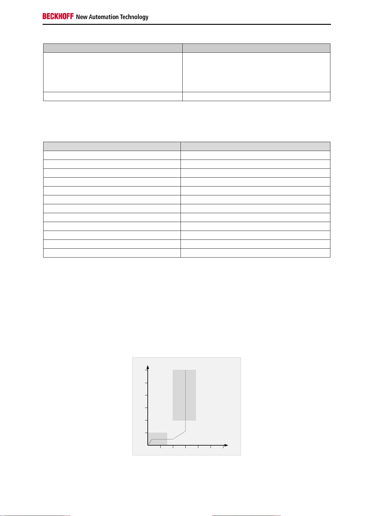
3.5 Characteristic curve of the inputs
The characteristic curve of the inputs is similar to type 3 according to EN 61131-2.
(V)
V
in
30
25
20
15
10
5
OFF
ON
I
123456
in
(mA)
EL1904 15
Page 18

Product description
3.6 Dimensions
Width: 12 mm (side-by-side installation)
Height: 100 mm
Depth 68 mm
16 EL1904
Page 19
Product description
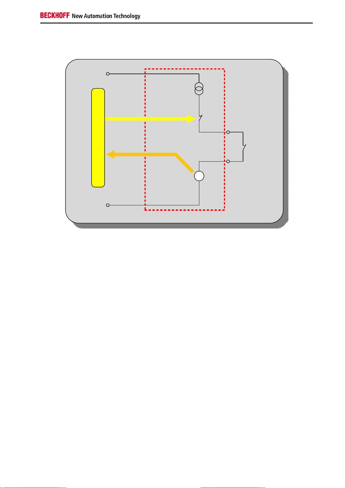
3.7 Block diagram EL1904
24V
0V
TwinSAFE
Reading
inputvoltage
Current
limit
Test
input
U
4ti me s,
oneforeach
channel
Contact
The block diagram shows the basic configuration of a channel in the EL1904. The part with a red border
is present four times in the terminal.
EL1904 17
Page 20
Operation
4 Operation
Please ensure that the TwinSAFE terminals are only transported, stored and operated under the specified
conditions (see technical data)!
Caution - Risk of injury!
WARNING
Attention
The TwinSAFE terminals must not be used under the following operating conditions:
under the influence of ionizing radiation
in corrosive environments
in an environment that leads to unacceptable soiling of the Bus Terminal
Electromagnetic compatibility
The TwinSAFE components comply with the current standards on electromagnetic
compatibility with regard to spurious radiation and immunity to interference in
particular.
However, in cases where devices such as mobile phones, radio equipment,
transmitters or high-frequency systems that exceed the interference emissions limits
specified in the standards are operated near TwinSAFE components, the function of
the TwinSAFE components may be impaired.
4.1 Installation
4.1.1 Safety instructions
Before installing and commissioning the TwinSAFE terminals please read the safety notes in the foreword
of this documentation.
4.1.2 Transport / storage
Use the original packaging for transporting or storing the digital TwinSAFE terminals.
Note the specified environmental conditions
CAUTION
Please ensure that the digital TwinSAFE terminals are only transported and stored
under the specified environmental conditions (see technical data).
18 EL1904
Page 21

Operation
4.1.3 Mechanical installation
Serious risk of injury!
DANGER
4.1.3.1 Control cabinet
The TwinSAFE terminals must be installed in a control cabinet or terminal box with IP54 protection class
according to IEC 60529 as a minimum.
4.1.3.2 Installation position and minimum distances
For the prescribed installation position the mounting rail is installed horizontally and the mating surfaces
of the EL/KL terminals point toward the front (see illustration below). The terminals are ventilated from
below, which enables optimum cooling of the electronics through convection. The direction indication
“down” corresponds to the direction of positive acceleration due to gravity.
Bring the bus system into a safe, de-energized state before starting installation,
disassembly or wiring of the Bus Terminals!
In order to ensure optimum convection cooling, the distances to neighboring devices and to control
cabinet walls must not be smaller than those shown in the diagram.
EL1904 19
Page 22
Operation
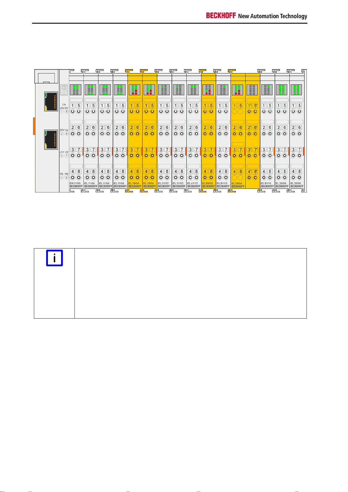
4.1.3.3 Example configuration for temperature measurement
The example configuration for the temperature measurement consists of an EK1100 EtherCAT coupler
with connected terminals that match the typical distribution of digital and analog signal types at a
machine. On the EL6900 a safety project is active, which reads safe inputs and enables all 4 safe outputs
during the measurement.
External heat sources / radiant heat / impaired convection
Note
The maximum permissible ambient temperature of 55°C was checked with the above
example configuration. Impaired convection, an unfavorable location near heat sources
or an unfavorable configuration of the EtherCAT Terminals may result in overheating of
the terminals.
The key parameter is always the maximum permitted internally measured temperature
of 95°C, above which the TwinSAFE terminals switch to safe state and report an error.
The internal temperature can be read from the TwinSAFE components via CoE (see
section 4.4.2 Diagnostic objects).
20 EL1904
Page 23
Operation
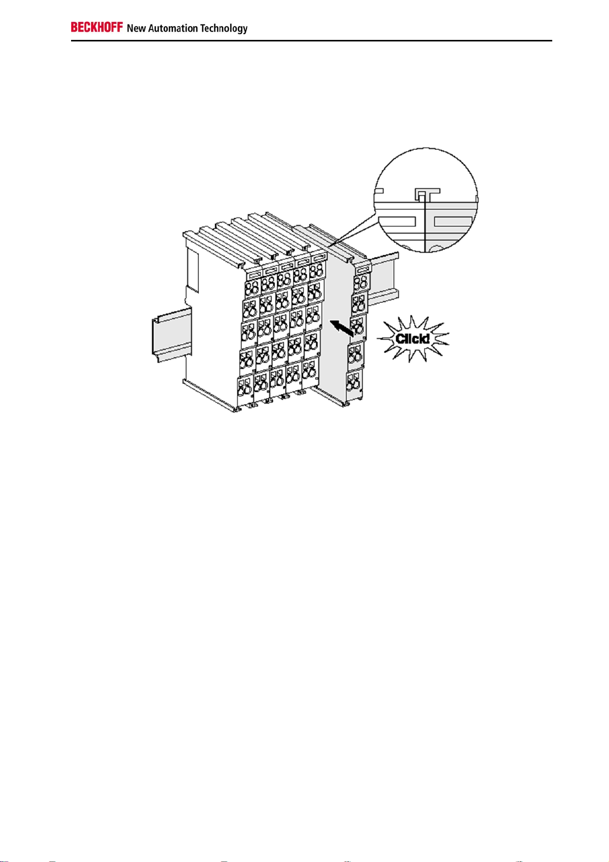
4.1.3.4 Mounting rail installation
Installation
The Bus Couplers and Bus Terminals are attached to commercially available 35 mm mounting rails
(according to EN 50022) by applying slight pressure:
1.
First attach the Fieldbus Coupler to the mounting rail.
2.
The Bus Terminals are now attached on the right-hand side of the fieldbus Coupler. Join the
components with slot and key and push the terminals against the mounting rail, until the lock
clicks onto the mounting rail.
If the terminals are clipped onto the mounting rail first and then pushed together without slot
and key, the connection will not be operational! When correctly assembled, no significant gap
should be visible between the housings.
3.
During the installation of the Bus Terminals, the locking mechanism of the terminals must not
come into conflict with the fixing bolts of the mounting rail.
EL1904 21
Page 24
Operation
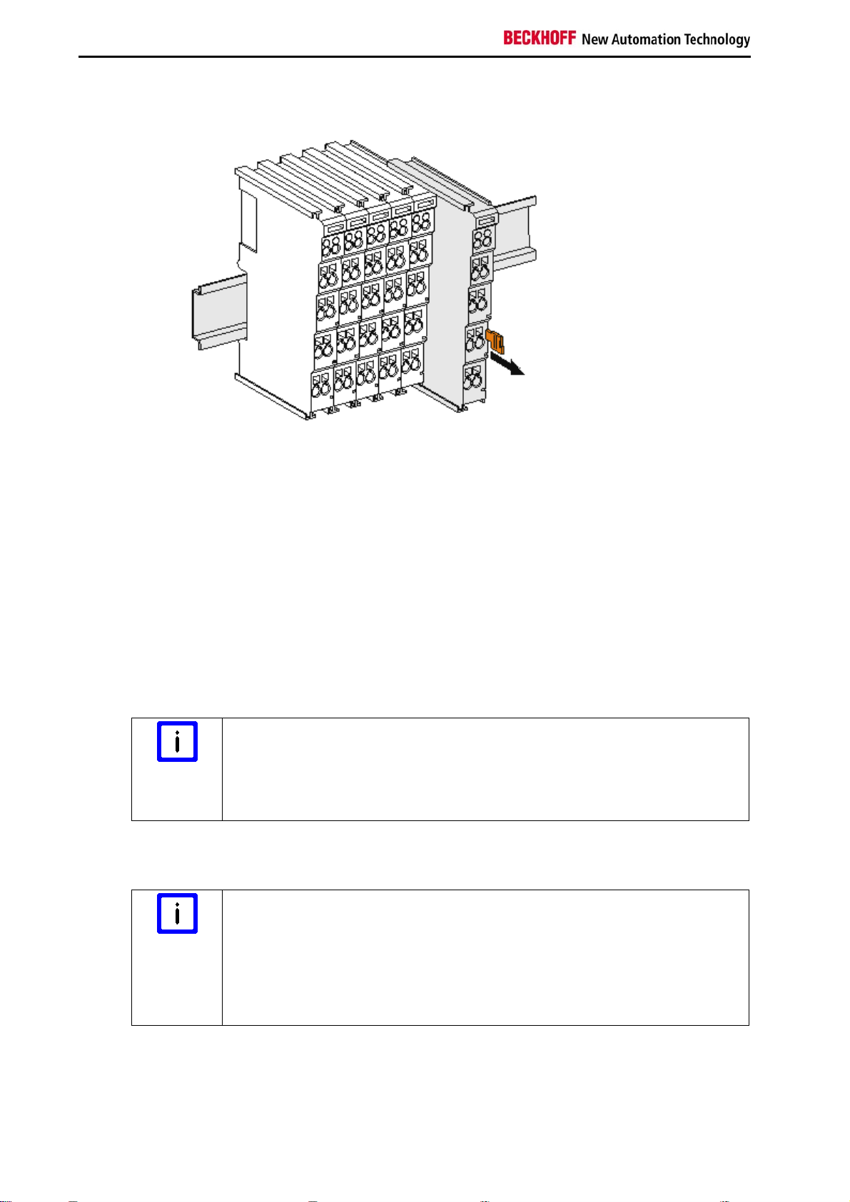
Removal
1. Carefully pull the orange-colored lug approximately 1 cm out of the terminal to be disassembled,
until it protrudes loosely. The lock with the mounting rail is now released for this terminal, and the
terminal can be pulled from the mounting rail without excessive force.
2. Grasp the released terminal with thumb and index finger simultaneous at the upper and lower
grooved housing surfaces and pull the terminal away from the mounting rail.
4.1.4 Electrical installation
4.1.4.1 Connections within a Bus Terminal block
The electric connections between the Bus Coupler and the Bus Terminals are automatically realized by
joining the components:
The six spring contacts of the E-bus deal with the transfer of the data and the supply of the Bus
Terminal electronics.
Note the maximum E-bus current!
Note
The power contacts deal with the supply for the field electronics and thus represent a supply rail
within the Bus Terminal block. The power contacts are supplied via terminals on the Bus Coupler.
Note
Observe the maximum current that your Bus Coupler can supply to the E-bus!
Use the EL9410 Power Supply Terminal if the current consumption of your
terminals exceeds the maximum current that your Bus Coupler can feed to the
E-bus supply.
Note the pin assignment of the power contacts!
During the design of a Bus Terminal block, the pin assignment of the individual
Bus Terminals must be taken account of, since some types (e.g. analog Bus
Terminals or digital 4-channel Bus Terminals) do not or not fully loop through the
power contacts.
Power Feed Terminals (EL91xx, EL92xx) interrupt the power contacts and thus
represent the start of a new supply rail.
22 EL1904
Page 25
Operation
PE power contact
The power contact labelled PE can be used as a protective earth. For safety reasons this contact mates
first when plugging together, and can ground short-circuit currents of up to 125 A.
Insulation tests
CAUTION
Note that, for reasons of electromagnetic compatibility, the PE contacts are
capacitatively coupled to the mounting rail. This may lead to incorrect results during
insulation testing or to damage on the terminal (e.g. disruptive discharge to the PE line
during insulation testing of a consumer with a rated voltage of 230 V).
For insulation testing, disconnect the PE supply line at the Bus Coupler or the Power
Feed Terminal! In order to decouple further feed points for testing, these Power Feed
Terminals can be released and pulled at least 10 mm from the group of terminals.
Serious risk of injury!
The PE power contact must not be used for other potentials!
DANGER
4.1.4.2 Overvoltage protection
If protection against overvoltage is necessary in your plant, provide a surge filter for the voltage supply to
the Bus Terminal blocks and the TwinSAFE terminals.
EL1904 23
Page 26
Operation
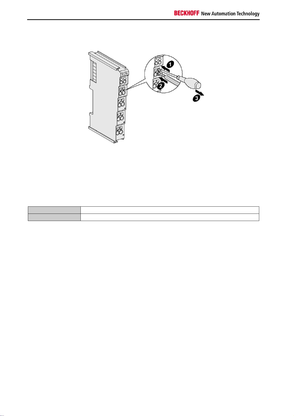
4.1.4.3 Wiring
Up to eight connections enable the connection of solid or finely stranded cables to the Bus Terminals.
The terminals are implemented in spring force technology. Connect the cables as follows:
1. Open a spring-loaded terminal by slightly pushing with a screwdriver or a rod into the
square opening above the terminal.
2. The wire can now be inserted into the round terminal opening without any force.
3. The terminal closes automatically when the pressure is released, holding the wire safely
and permanently.
Wire cross section
Strip length
0,08 ... 2.5 mm
8...9 mm
2
24
EL1904
Page 27
Operation
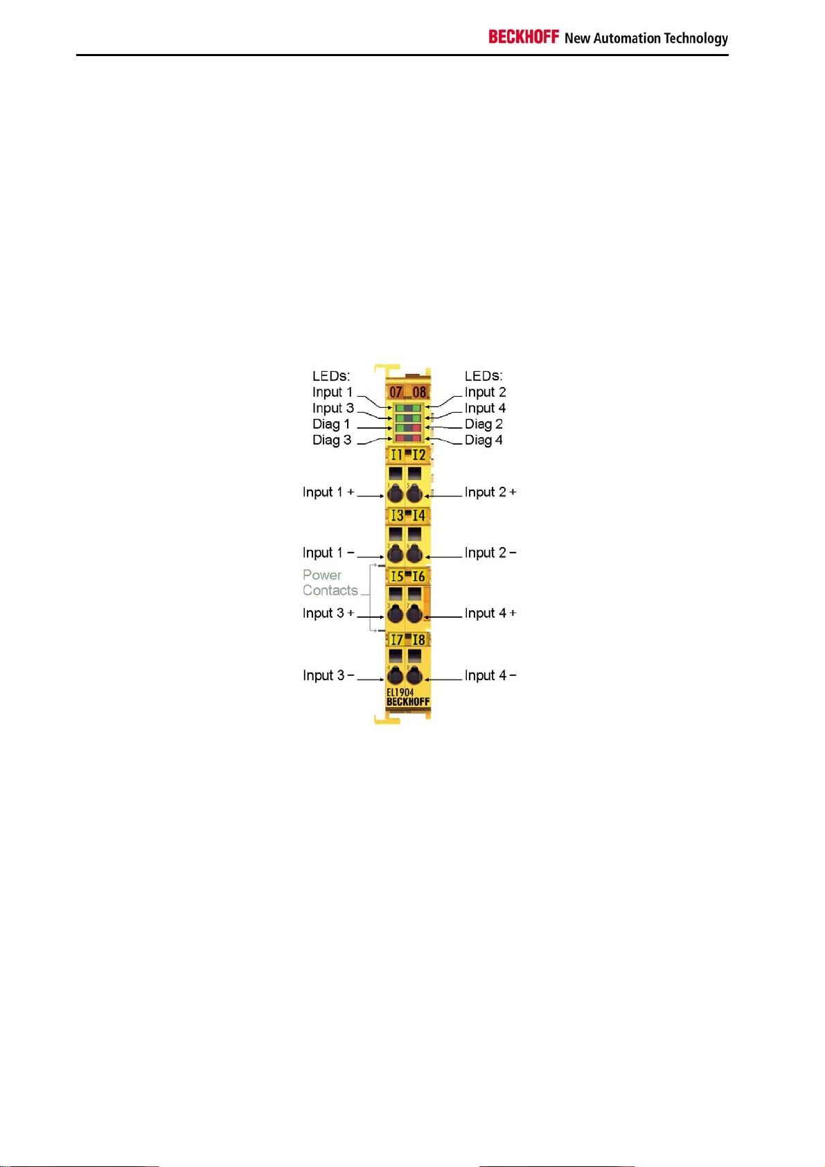
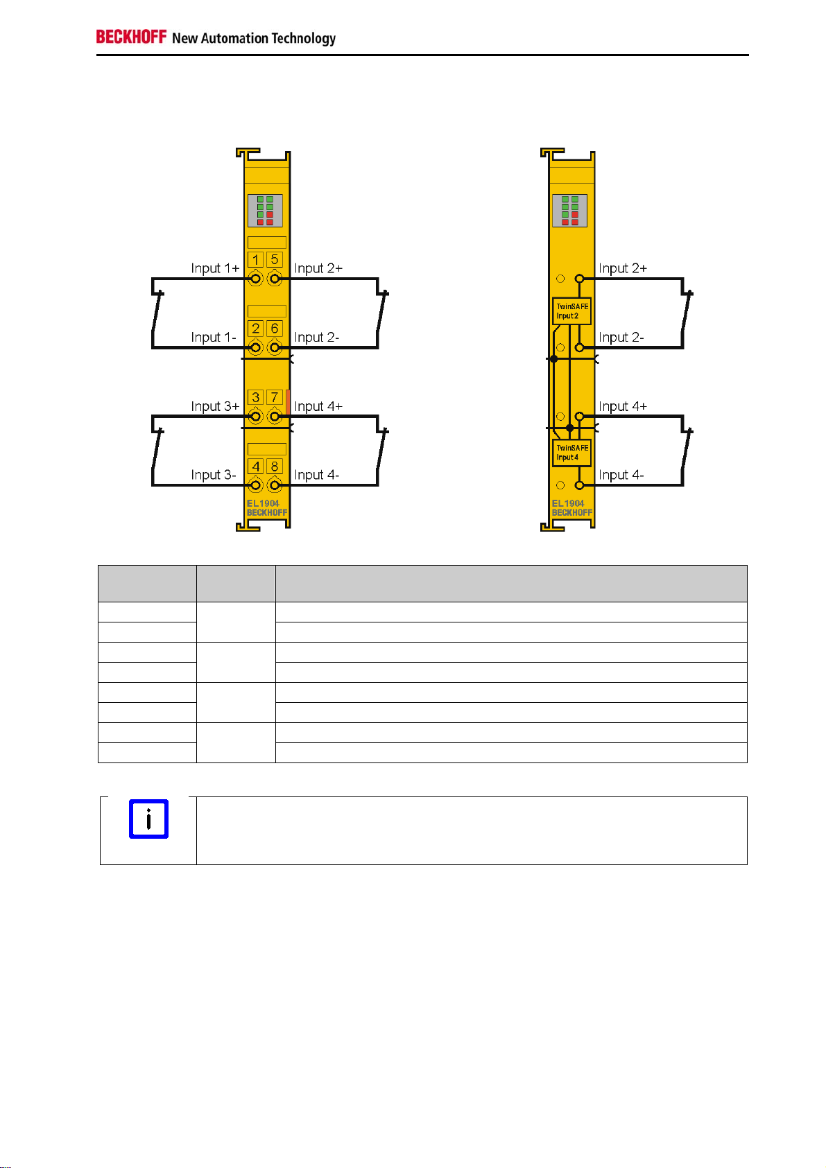
EL1904 pin assignment
Terminal
Input Signal
point
1 1 Input 1+
2 Input 13 3 Input 3+
4 Input 35 2 Input 2+
6 Input 27 4 Input 4+
8 Input 4-
Configurable inputs
Note
The inputs 1 to 4 can be occupied as you want with normally closed contacts or
normally open contacts. The corresponding analysis is carried out in the safety PLC.
EL1904 25
Page 28
Operation
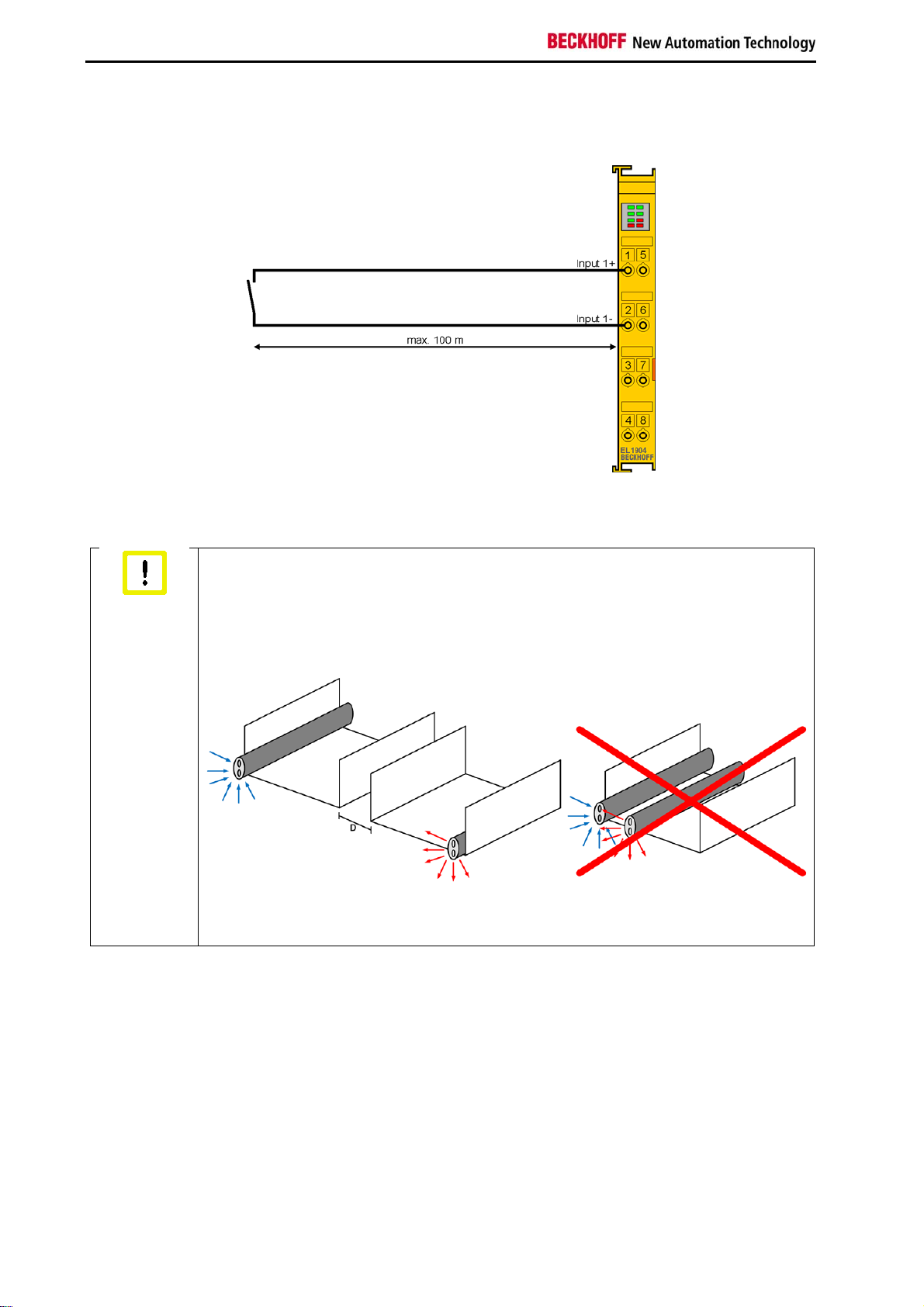
Permitted cable length
When connecting a single switching contact via its own continuous cabling (or via a non-metallic
sheathed cable), the maximum permitted cable length is 100 m.
Route the signal cable separately
Attention
The signal cable must be routed separately from potential sources of interference, such
as motor supply cables, 230 V
power cables etc.!
AC
Interference caused by cables routed in parallel can influence the signal form of the
test pulses and thus cause diagnostic messages (e.g. sensor errors).
D - Distance between the cable ducts should be as large as possible
Blue arrows - signal line
Red arrows - potential source of interference
The common routing of signals together with other clocked signals in a common cable also reduces the
maximum propagation, since crosstalk of the signals can occur over long cable lengths and cause
diagnostic messages. The test pulses can be switched off (sensor test parameter) if the connection of a
common cable is unavoidable. However, this then leads to a reduction in the degree of diagnostic cover
when calculating the performance level.
The use of contact points, plug connectors or additional switching contacts in the cabling also reduces the
maximum propagation.
The typical length of a test pulse (switching from 24 V to 0 V and back to 24 V) is 350 µs and takes place
approx. 250 times per second.
26
EL1904
Page 29
Operation
4.1.5 Tested devices
The following list contains devices that were tested together with the EL1904 TwinSAFE terminal. The
results only apply for the current device hardware version at the time of testing. The tests were carried out
in a laboratory environment. Modifications of these products cannot be considered here. If you are unsure
please test the hardware together with the TwinSAFE terminal.
Manufacturer Type Comment
SICK C4000
SICK
Wenglor
S3000 Safety laser scanner
SG2-14ISO45C1 Safety light grids
Leuze lumiflex ROBUST 42/43/44 Safety light barriers
Schmersal BNS250-11ZG Safety switch
ifm GM701S Inductive safety sensor
Keyence SL-V (with PNP cable set) Safety light curtain
Safety light curtain
The tests were carried out as function tests only. The information provided in the respective manufacturer
documentation remains valid.
EL1904 27
Page 30
Operation
4.2 Operation in potentially explosive atmospheres (ATEX)
4.2.1 Special conditions
Observe the special conditions for the intended use of Beckhoff fieldbus
components in potentially explosive areas (directive 94/9/EU)!
WARNING
The certified components are to be installed in a suitable housing that
guarantees a protection class of at least IP54 in accordance with EN 60529!
The environmental conditions during use are thereby to be taken into account!
If the temperatures during rated operation are higher than 70 °C at the feed-in
points of cables, lines or pipes, or higher than 80°C at the wire branching
points, then cables must be selected whose temperature data correspond to
the actual measured temperature values!
Observe the permissible ambient temperature range of 0 to 55 °C when using
Beckhoff fieldbus components in potentially explosive atmospheres!
Measures must be taken to protect against the rated operating voltage being
exceeded by more than 40% due to short-term interference voltages!
The individual terminals may only be unplugged or removed from the Bus
Terminal system if the supply voltage has been switched off or if a nonexplosive atmosphere is ensured!
The connections of the certified components may only be connected or
disconnected if the supply voltage has been switched off or if a non-explosive
atmosphere is ensured!
The fuses of the KL92xx feed terminals may only be exchanged if the supply
voltage has been switched off or if a non-explosive atmosphere is ensured!
Address selectors and ID switches may only be adjusted if the supply voltage
has been switched off or if a non-explosive atmosphere is ensured!
The fundamental health and safety requirements are fulfilled by compliance with the following standards:
EN 60079-0: 2006
EN 60079-15: 2005
28 EL1904
Page 31
Operation
4.2.2 Identification
Beckhoff fieldbus components that are certified for use in potentially explosive atmospheres bear one of
the following markings:
or
II 3 G Ex nA II T4
KEMA 10ATEX0075 X Ta: 0 - 55°C
II 3 G Ex nA nC IIC T4 KEMA 10ATEX0075 X Ta: 0 - 55°C
4.2.3 Date code and serial number
The TwinSAFE terminals bear a date code, which is composed as follows:
Date code: CW YY SW HW
Legend:
CW: Calendar week of manufacture
YY: Year of manufacture
SW: Software version
HW: Hardware version
Example: Date code 29 10 02 01
Calendar week: 29
Year: 2010
Software version: 02
Hardware version: 01
In addition the TwinSAFE terminals bear a unique serial number.
4.2.4 Further ATEX documentation
Please also refer to the further documentation
Note
EL1904 29
Notes regarding application of the Bus Terminal system in areas potentially explosive
atmosphere are available in the Download section of the Beckhoff website at
http://www.beckhoff.de.
Page 32

Operation
4.3 Configuration of the EL1904 in the TwinCAT System
Manager
Do not change CoE objects!
CAUTION
4.3.1 Inserting a Beckhoff Bus Coupler
See TwinCAT automation software documentation.
4.3.2 Inserting a Beckhoff Bus Terminal
See TwinCAT automation software documentation.
Do not change any of the CoE objects in the TwinSAFE terminals. Any modifications
(e.g. via the System Manager) of the CoE objects would permanently set the terminals
to the Fail-Stop state or result in unexpected behavior of the terminals!
4.3.3 Inserting an EL1904
An EL1904 is inserted in the same way as any other Beckhoff Bus Terminal. In the list open Safety
Terminals (ELx9xx) and select the EL1904.
30 EL1904
Page 33
Operation
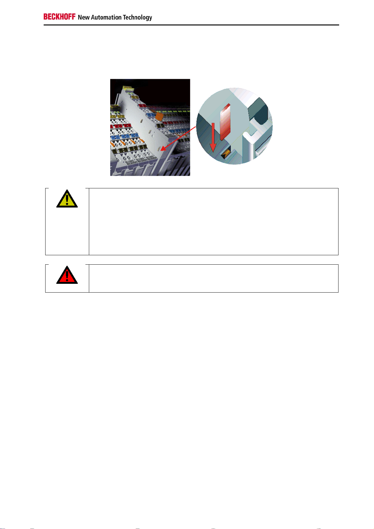
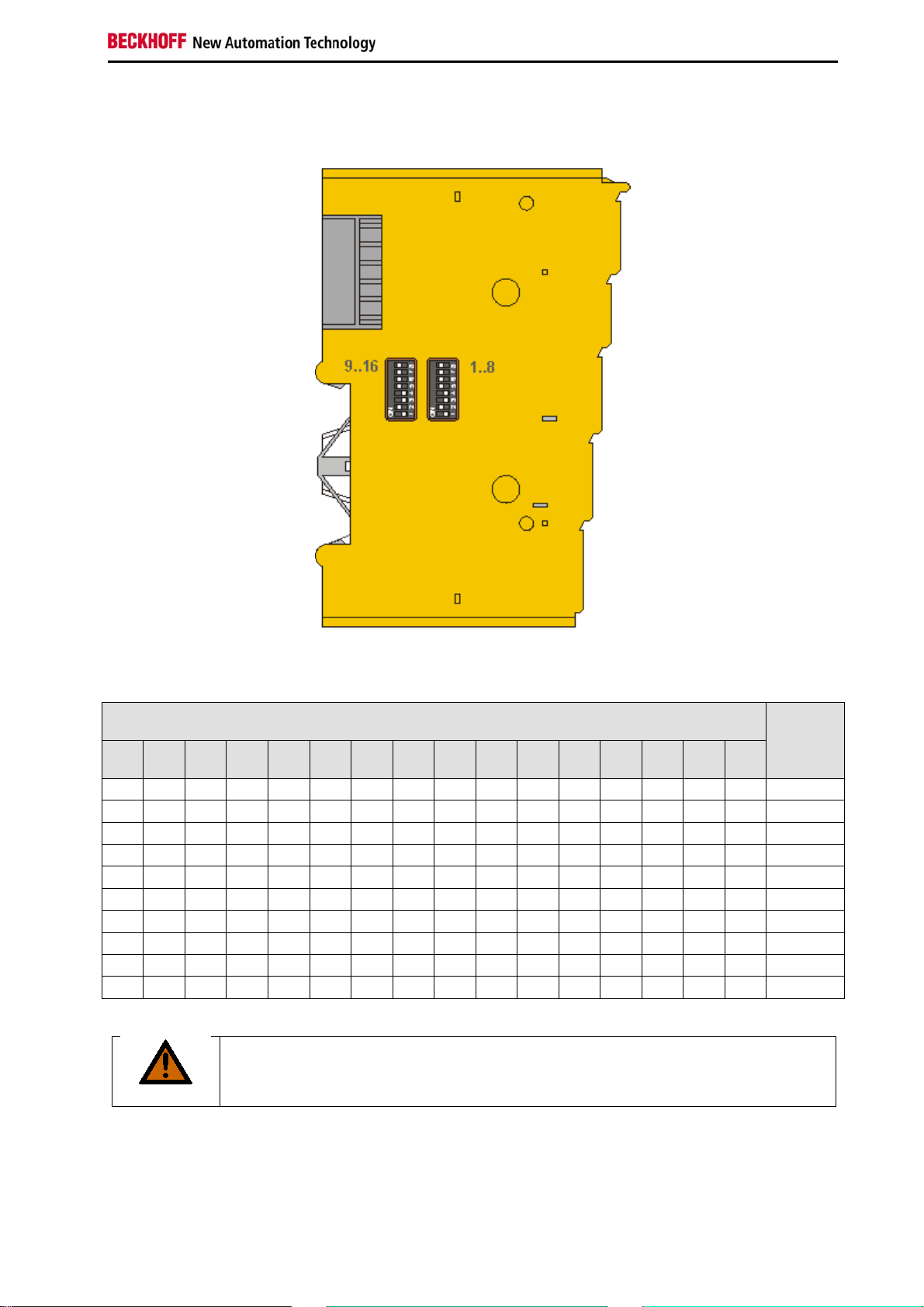
4.3.4 Address settings on the TwinSAFE terminals
Set the TwinSAFE address for the terminal using the two dip switches (with 8 setting options) on the lefthand side of the EL1904 TwinSAFE terminal. TwinSAFE addresses between 1 and 65535 are available.
DIP switches Addres
s
1 2 3 4 5 6 7 8 9 10 11 12 13 14 15 16
ON OFF OFF OFF OFF OFF OF OF OF OF OF OF OF OF OF OF
OFF ON OFF OFF OFF OFF OF OF OF OF OF OF OF OF OF OF
ON ON OFF OFF OFF OFF OF OF OF OF OF OF OF OF OF OF
OFF OFF ON OFF OFF OFF OF OF OF OF OF OF OF OF OF OF
ON OFF ON OFF OFF OFF OF OF OF OF OF OF OF OF OF OF
OFF ON ON OFF OFF OFF OF OF OF OF OF OF OF OF OF OF
ON ON ON OFF OFF OFF OF OF OF OF OF OF OF OF OF OF
OFF OFF OFF ON OFF OFF OF OF OF OF OF OF OF OF OF OF
… … … … … … … … … … … … … … … …
ON ON ON ON ON ON ON ON ON ON ON ON ON ON ON ON
65535
Unique TwinSAFE address
1
2
3
4
5
6
7
8
…
Each TwinSAFE address may only be used once within a network!
WARNING
EL1904 31
Page 34

Operation
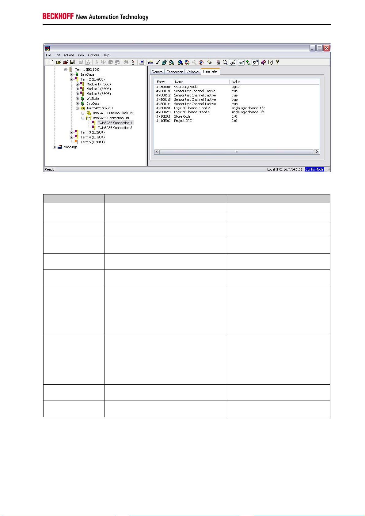
4.3.5 Entering a TwinSAFE address and parameters in the System Manager
The TwinSAFE address set at the DIP switch must also be entered in tab FSoE (under FSoE address)
under the EL1904.
The EL1904 parameters are set under the respective TwinSAFE connection in the Connection and
Parameter tabs.
32 EL1904
Page 35
Operation
Parameter overview
PrmName Meaning Values
FSoE_Address DIP switch address 1 to 65535
Operating Mode Digital / standstill monitoring 1 and 2 Digital / standstill 1 and 2
Sensor test channel
1 active
Sensor test channel
2 active
Sensor test channel
3 active
Sensor test channel
4 active
Logic channel 1
and 2
The clock signal for connection Input1+ is
true / false
checked at connection Input1-.
The clock signal for connection Input2+ is
true / false
checked at connection Input2-.
The clock signal for connection Input3+ is
true / false
checked at connection Input3-.
The clock signal for connection Input4+ is
true / false
checked at connection Input4-.
Logic of channels 1 and 2 - single logic
- asynchronous repetition OSSD
(sensor test must be switched off)
- any pulse repetition OSSD
(sensor test must be switched off)
- short cut is no module fault
Logic channel 3
and 4
Logic of channels 3 and 4 - single logic
- asynchronous repetition OSSD
(sensor test must be switched off)
- any pulse repetition OSSD
(sensor test must be switched off)
- short cut is no module fault
Store Code This parameter is required for the
0x0000
TwinSAFE Restore Mode
Project CRC This parameter is required for the
0x0000
TwinSAFE Restore Mode
EL1904 33
Page 36
Operation
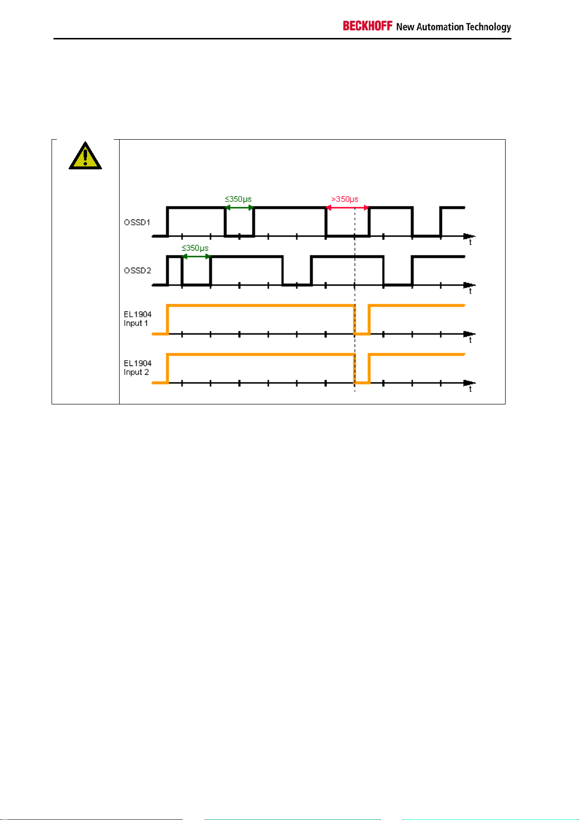
4.3.5.1 EL1904 configuration for light barriers, light grids, light curtains etc.
The EL1904 also supports direct connection of contact-free protective devices with two self-testing
outputs such as light barriers, light grids, light curtains, laser scanners, etc.
Sensors with self-testing outputs
CAUTION
Only sensors with self-testing outputs and a maximum sensor self-test duration of
350 µs may be connected to the EL1904.
Parameter
To connect these sensors please set the following parameters for the EL1904 in the TwinCAT System
Manager:
Connect the two sensor signals either to channels 1 and 2 or channels 3 and 4 and activate
asynchronous repetition OSSD or any pulse repetition for the two inputs used under parameter
Logic for channel x and y. The difference between these settings is that with any pulse repetition
simultaneous tests of the OSSD signals up to 350 µs are allowed.
For the two inputs used set the sensor test for the EL1904 to false.
4.3.5.2 Configuration of the EL1904 for safety switching mats
The EL1904 also supports direct connection of safety switching mats.
Parameter
To connect these switching mats please set the following parameters for the EL1904 in the TwinCAT
System Manager:
Connect the two sensor signals either to channels 1 and 2 or channels 3 and 4 and activate short
cut channel x/y is no module fault for the two inputs used under parameter Logic for channel x
and y.
34 EL1904
Page 37
Operation
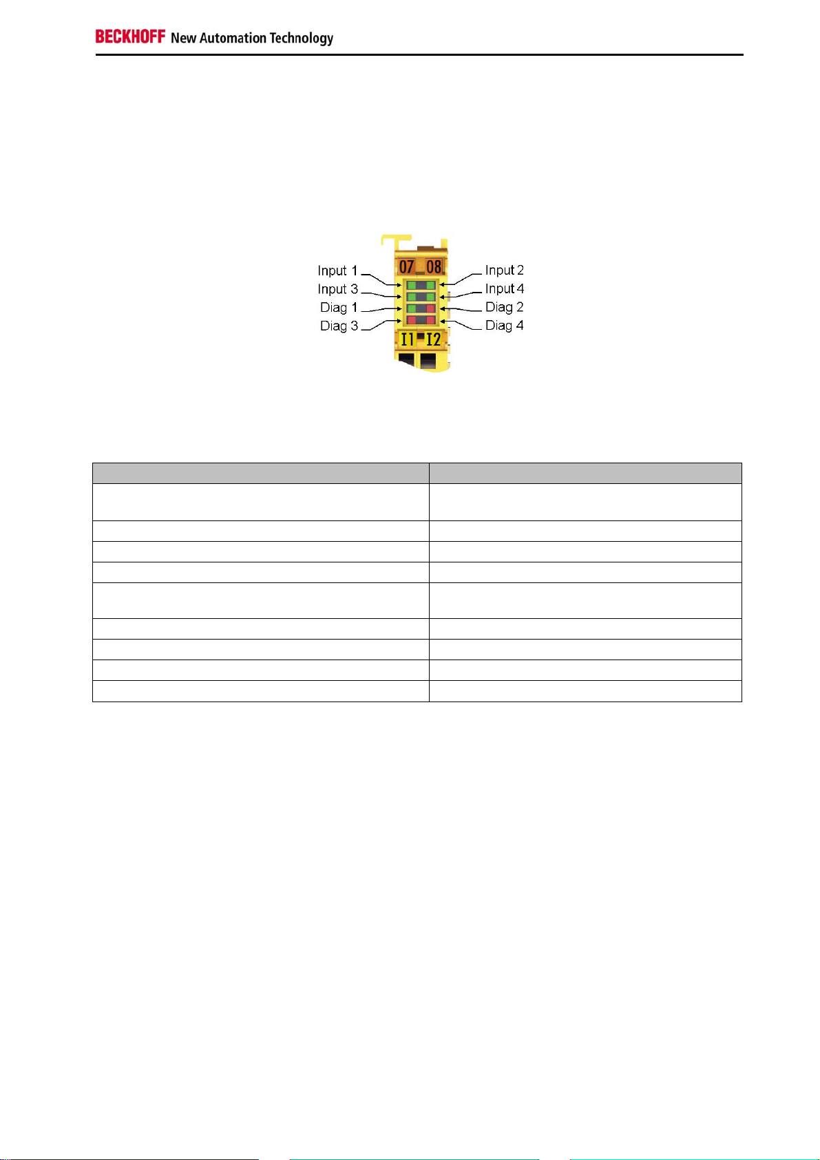
4.4 Diagnostics
4.4.1 Diagnostic LEDs
The LEDs Diag 1 to Diag 4 display diagnostic information for the EL1904.
4.4.1.1 Diag 1 (green)
The Diag 1 LED indicates the state of the TwinSAFE interface.
Flashing Code Meaning
LED illuminated continuously normal operation:
TwinSAFE communication OK
rapid flickering, alternating with 1 flash pulse Error in S parameter (TwinSAFE parameter)
rapid flickering, alternating with 2 flash pulses Error in I parameter (Individual parameter)
rapid flickering, alternating with 3 flash pulses Waiting for S and I parameter
rapid flickering, alternating with 4 flash pulses S- and I-parameter correct:
waiting for first host message
rapid flickering, alternating with 5 flash pulses Watchdog error
rapid flickering, alternating with 6 flash pulses CRC error
rapid flickering, alternating with 7 flash pulses Sequence number error
rapid flickering, alternating with 8 flash pulses Communication error in the TwinSAFE protocol
4.4.1.2 Diag 2 (red)
The Diag 2 LED illuminates red if the terminal detects an external supply or cross-circuit. The LED
extinguishes once the error is rectified.
EL1904 35
Page 38
Operation
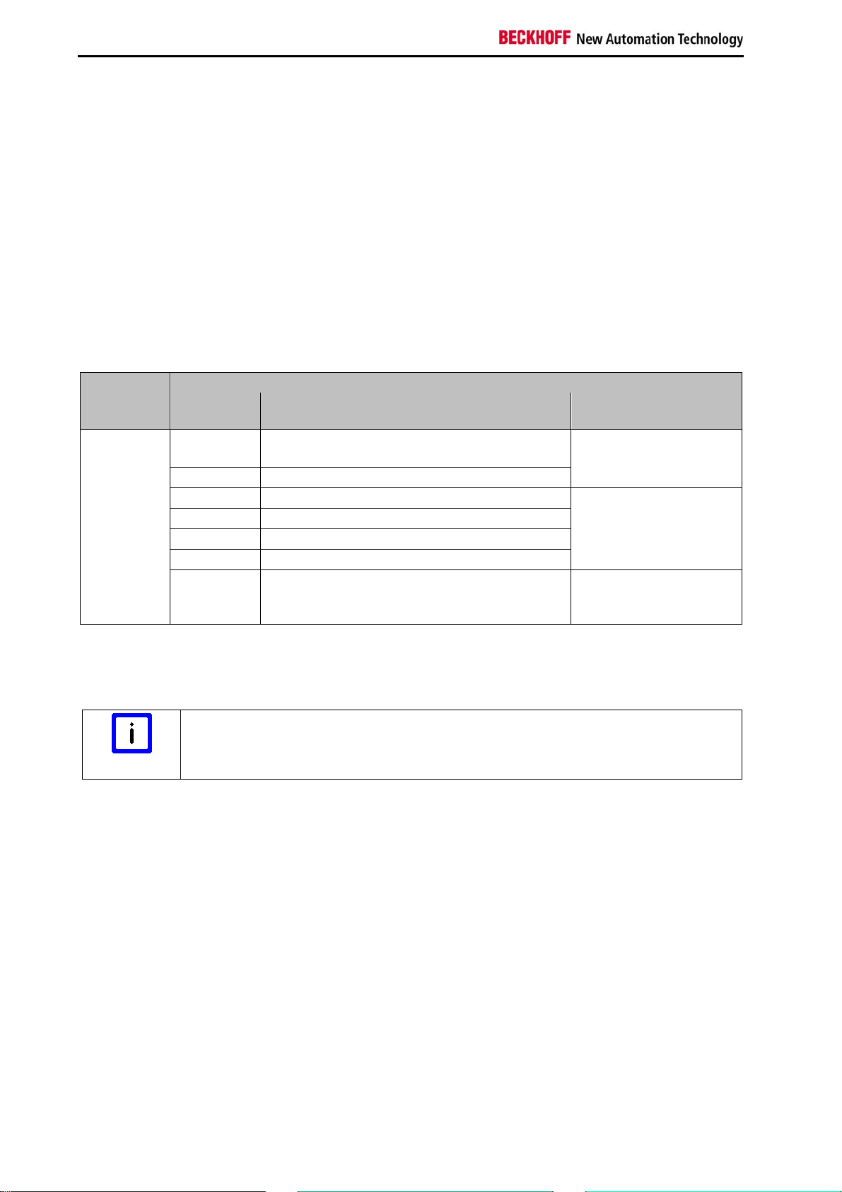
4.4.1.3 Diag 3 (red) and Diag 4 (red)
If the Diag 3 LED is lit, the Diag 4 LED indicates internal terminal errors.
Flashing Codes
In the case of such an error, the Diag 4 LED on the EL1904 displays flashing codes that describe the
error in more detail.
A flashing code consists of four sequences, which are interrupted in each case by a short break. After the
four sequences there is a long break, following which the flashing code is displayed again.
Count the individual sequences of the flashing code.
The errors indicated by the following flashing codes are reversible. After successful troubleshooting the
terminal can be restarted.
Diag 3 LED Diag 4 LED
Flashing
Meaning Remedy
Code
lit 6-1-1-1 max. internal temperature exceeded
7-1-1-1 internal temperature below min. value
Ensure observance of
the permissible ambient
temperature.
2-1-2-1 max. supply voltage µC1 exceeded Check the supply
3-1-2-1 max. supply voltage µC2 exceeded
voltage.
4-1-2-1 voltage fell below min. supply voltage µC1
5-1-2-1 voltage fell below min. supply voltage µC2
8-1-1-1 Temperature difference between the measuring
points exceeded
Check the installation
position and the ambient
temperature.
If another flashing code is displayed, this means that there is an internal terminal error that has stopped
the terminal. In this case the terminal must be checked by Automation GmbH & Co. KG.
Note the flashing codes and return the terminal
Note
Note the flashing code displayed and include this information with the terminal when
you return it.
36 EL1904
Page 39
Operation
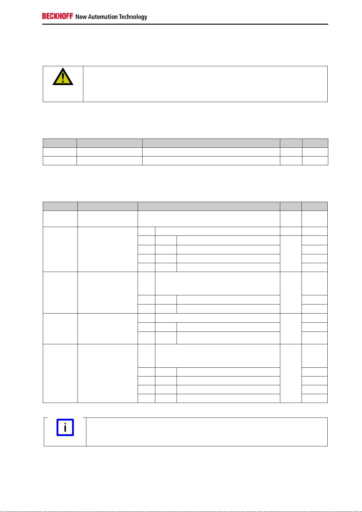
4.4.2 Diagnostic objects
Do not change CoE objects!
CAUTION
The CoE objects FA80
Do not change any of the CoE objects in the TwinSAFE terminals! Any modifications
(e.g. via the TwinCAT System Manager) in the CoE objects permanently put the
terminals in the fail-stop state or result in unexpected behavior of the terminals!
indicate the current internal temperature values of the EL1904.
hex
Index FA80
: Internal temperature values
hex
Index Name Meaning
Flags Default
FA80:01 Temperature 1 Temperature measurement 1 RO 0
FA80:02 Temperature 2 Temperature measurement 2 RO 0
The CoE objects 800E
Index 800E
: Diagnostic objects
hex
display further diagnostic information.
hex
Index Name Meaning
800E:0 Diag The following sub-indices contain detailed
Flags Default
RO
diagnostic information.
800E:0A Sensor test error Bit Error during the sensor test RO
800E:0B Error during two-
channel evaluation
0 1
1 1
2 1
3 1
Bit Error during the contiguous evaluation of
Error at input 1 0
bin
Error at input 2 0
bin
Error at input 3 0
bin
Error at input 4 0
bin
RO
two channels, i.e. the two channels
contradict each other.
800E:0C Error in the safety
mat operating
mode: input pair
disagree
800E:0D Error in the safety
mat operating
mode: external
supply
0 1
1 1
Bits Error in the input pair RO
1, 0 11
3, 2 11
Bit Error in the test pulses in the safety mat
0 1
1 1
2 1
3 1
Error in the first input pair 0
bin
Error in the second input pair 0
bin
Error in the first input pair 00
bin
Error in the second input pair 00
bin
RO
operating mode; i.e. the terminal has
detected an external supply.
Error at input 1 0
bin
Error at input 2 0
bin
Error at input 3 0
bin
Error at input 4 0
bin
bin
bin
bin
bin
bin
bin
bin
bin
bin
bin
bin
bin
bin
bin
Differing diagnostic messages possible
Note
Due to the variable order or execution of the test series, diagnostic messages differing
from those given in the table above are possible.
EL1904 37
Page 40

Operation
4.5 Maintenance
The TwinSAFE terminals are maintenance-free!
Observe the specified environmental conditions!
WARNING
If the terminal is operated outside the permitted temperature range it will switch to Global Fault state.
4.5.1 Cleaning
Protect the TwinSAFE terminal from unacceptable soling during operation and storage!
If the TwinSAFE terminals were subjected to unacceptable soiling they may no longer be operated!
Please ensure that the TwinSAFE terminals are only stored and operated under the
specified conditions (see technical data).
Have soiled terminals checked!
WARNING
Cleaning of the TwinSAFE terminal by the user is not permitted!
Please send soiled terminals to the manufacturer for inspection and cleaning!
4.5.2 Service life
The TwinSAFE terminals are designed for a service life of 20 years.
Due to the high diagnostic coverage within the lifecycle no special proof tests are required.
The TwinSAFE terminals bear a date code, which is composed as follows:
Date code: CW YY SW HW
Legend:
CW: Calendar week of manufacture
YY: Year of manufacture
SW: Software version
HW: Hardware version
In addition the TwinSAFE terminals bear a unique serial number.
Example: Date code 17 11 05 00
Calendar week: 17
Year: 2011
Software version: 05
Hardware version: 00
38 EL1904
Page 41
Operation
4.6 Decommissioning
Serious risk of injury!
DANGER
4.6.1 Disposal
In order to dispose of the device, it must be removed and fully dismantled.
Housing components (polycarbonate, polyamide (PA6.6)) are suitable for plastic recycling.
Metal parts can be sent for metal recycling.
Electronic parts such as disk drives and circuit boards must be disposed of in accordance with
national electronics scrap regulations.
Bring the bus system into a safe, de-energized state before starting disassembly of the
Bus Terminals!
EL1904 39
Page 42

Appendix
5 Appendix
5.1 Beckhoff Support and Service
Beckhoff and their partners around the world offer comprehensive support and service, making available
fast and competent assistance with all questions related to Beckhoff products and system solutions.
5.1.1 Beckhoff branches and partner companies Beckhoff Support
Please contact your Beckhoff branch office or partner company for local support and service on Beckhoff
products!
The contact addresses for your country can be found in the list of Beckhoff branches and partner
companies: www.beckhoff.com. You will also find further documentation for Beckhoff components there.
5.1.2 Beckhoff company headquarters
Beckhoff Automation GmbH & Co.KG
Huelshorstweg 20
33415 Verl
Germany
Phone: + 49 (0) 5246/963-0
Fax: + 49 (0) 5246/963-198
E-mail: info@beckhoff.com
Web: www.beckhoff.com
Beckhoff Support
Support offers you comprehensive technical assistance, helping you not only with the application of
individual Beckhoff products, but also with other, wide-ranging services:
world-wide support
design, programming and commissioning of complex automation systems
and extensive training program for Beckhoff system components
Hotline: + 49 (0) 5246/963-157
Fax: + 49 (0) 5246/963-9157
E-mail: support@beckhoff.com
Beckhoff Service
The Beckhoff Service Center supports you in all matters of after-sales service:
on-site service
repair service
spare parts service
hotline service
Hotline: + 49 (0) 5246/963-460
Fax: + 49 (0) 5246/963-479
E-mail: service@beckhoff.com
40 EL1904
Page 43
Appendix
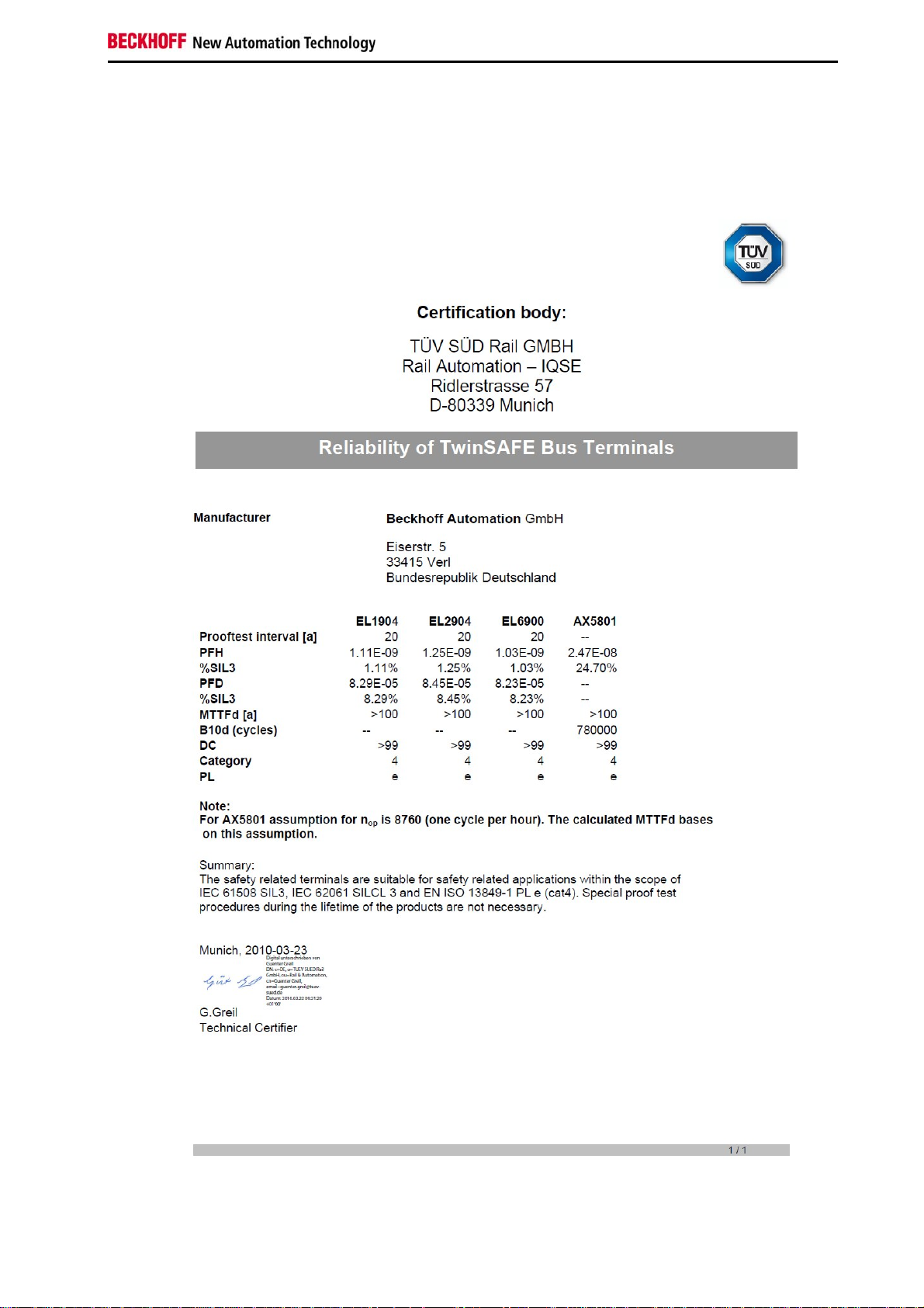
5.2 Certificates
EL1904 41
Page 44

Appendix
42 EL1904
 Loading...