

Page 1
Documentation | EN
EK9500
Ethernet/IP - Bus Coupler for EtherCAT Terminals
2020-11-16 | Version: 1.1.1
Page 2

Page 3

Table of contents
Table of contents
1 Foreword ....................................................................................................................................................5
1.1 Notes on the documentation..............................................................................................................5
1.2 Safety instructions .............................................................................................................................6
1.3 Documentation issue status ..............................................................................................................7
1.4 Version identification of EtherCAT devices .......................................................................................7
1.4.1 Beckhoff Identification Code (BIC)................................................................................... 11
2 Product overview.....................................................................................................................................13
2.1 EKxxxx - System overview ..............................................................................................................13
2.2 EK9500 - Introduction......................................................................................................................14
2.3 Technical data .................................................................................................................................15
3 Mounting and wiring................................................................................................................................16
3.1 Mounting..........................................................................................................................................16
3.1.1 Instructions for ESD protection ........................................................................................ 16
3.1.2 Dimensions ...................................................................................................................... 17
3.1.3 Installation on mounting rails – Bus Coupler ................................................................... 17
3.2 Wiring...............................................................................................................................................19
3.2.1 Power supply ................................................................................................................... 19
3.2.2 Ethernet ........................................................................................................................... 21
3.3 UL notice .........................................................................................................................................25
3.4 ATEX - Special conditions (standard temperature range) ...............................................................26
3.5 ATEX - Special conditions (extended temperature range) ..............................................................27
3.6 Continuative documentation about explosion protection .................................................................28
4 Parameterization and commissioning...................................................................................................29
4.1 Further interfaces ............................................................................................................................29
4.2 IP address .......................................................................................................................................29
4.3 DIP switch........................................................................................................................................29
5 Configuration ...........................................................................................................................................31
5.1 Configuration via the HTML pages of the Bus Coupler ...................................................................31
5.2 EtherCAT configuration ...................................................................................................................32
5.3 EtherNet/IP Configuration................................................................................................................35
5.4 EtherNet/IP Mapping .......................................................................................................................39
5.5 EK9500 - EtherCAT configurations .................................................................................................39
6 Error handling and diagnosis.................................................................................................................43
6.1 LED indicators .................................................................................................................................43
7 Appendix ..................................................................................................................................................46
7.1 Update Bus Coupler image .............................................................................................................46
7.2 Setting up the EK9500 in RS Logix Studio 5000 via EDS File ........................................................47
7.3 Setting up an EK9500 as a Generic Device in RS Logix Studio 5000.............................................49
7.4 Using the CtrlStatus DWORD..........................................................................................................51
7.5 Supported CIP objects.....................................................................................................................51
7.6 FAQ .................................................................................................................................................53
7.7 List of Abbreviations ........................................................................................................................53
7.8 Support and Service ........................................................................................................................55
EK9500 3Version: 1.1.1
Page 4

Table of contents
EK95004 Version: 1.1.1
Page 5

Foreword
1 Foreword
1.1 Notes on the documentation
Intended audience
This description is only intended for the use of trained specialists in control and automation engineering who
are familiar with the applicable national standards.
It is essential that the documentation and the following notes and explanations are followed when installing
and commissioning these components.
It is the duty of the technical personnel to use the documentation published at the respective time of each
installation and commissioning.
The responsible staff must ensure that the application or use of the products described satisfy all the
requirements for safety, including all the relevant laws, regulations, guidelines and standards.
Disclaimer
The documentation has been prepared with care. The products described are, however, constantly under
development.
We reserve the right to revise and change the documentation at any time and without prior announcement.
No claims for the modification of products that have already been supplied may be made on the basis of the
data, diagrams and descriptions in this documentation.
Trademarks
Beckhoff®, TwinCAT®, EtherCAT®, EtherCATG®, EtherCATG10®, EtherCATP®, SafetyoverEtherCAT®,
TwinSAFE®, XFC®, XTS® and XPlanar® are registered trademarks of and licensed by Beckhoff Automation
GmbH. Other designations used in this publication may be trademarks whose use by third parties for their
own purposes could violate the rights of the owners.
Patent Pending
The EtherCAT Technology is covered, including but not limited to the following patent applications and
patents: EP1590927, EP1789857, EP1456722, EP2137893, DE102015105702 with corresponding
applications or registrations in various other countries.
EtherCAT® is registered trademark and patented technology, licensed by Beckhoff Automation GmbH,
Germany.
Copyright
© Beckhoff Automation GmbH & Co. KG, Germany.
The reproduction, distribution and utilization of this document as well as the communication of its contents to
others without express authorization are prohibited.
Offenders will be held liable for the payment of damages. All rights reserved in the event of the grant of a
patent, utility model or design.
EK9500 5Version: 1.1.1
Page 6
Foreword
1.2 Safety instructions
Safety regulations
Please note the following safety instructions and explanations!
Product-specific safety instructions can be found on following pages or in the areas mounting, wiring,
commissioning etc.
Exclusion of liability
All the components are supplied in particular hardware and software configurations appropriate for the
application. Modifications to hardware or software configurations other than those described in the
documentation are not permitted, and nullify the liability of Beckhoff Automation GmbH & Co. KG.
Personnel qualification
This description is only intended for trained specialists in control, automation and drive engineering who are
familiar with the applicable national standards.
Description of instructions
In this documentation the following instructions are used.
These instructions must be read carefully and followed without fail!
DANGER
Serious risk of injury!
Failure to follow this safety instruction directly endangers the life and health of persons.
WARNING
Risk of injury!
Failure to follow this safety instruction endangers the life and health of persons.
CAUTION
Personal injuries!
Failure to follow this safety instruction can lead to injuries to persons.
NOTE
Damage to environment/equipment or data loss
Failure to follow this instruction can lead to environmental damage, equipment damage or data loss.
Tip or pointer
This symbol indicates information that contributes to better understanding.
EK95006 Version: 1.1.1
Page 7

1.3 Documentation issue status
Version Comment
1.1.1 • Update chapter “Technical data”
• Update structure
1.1.0 • Update chapter “Technical data”
• Update structure
1.0.0 • 1st Public issue EK9500
• Addenda
0.0.4 • Corrections
0.0.3 • Addenda CIP objects
0.0.2 • Addenda, corrections
0.0.1 • Preliminary version
1.4 Version identification of EtherCAT devices
Designation
Foreword
A Beckhoff EtherCAT device has a 14-digit designation, made up of
• family key
• type
• version
• revision
Example Family Type Version Revision
EL3314-0000-0016 EL terminal
(12 mm, nonpluggable connection
level)
ES3602-0010-0017 ES terminal
(12 mm, pluggable
connection level)
CU2008-0000-0000 CU device 2008 (8-port fast ethernet switch) 0000 (basic type) 0000
Notes
• The elements mentioned above result in the technical designation. EL3314-0000-0016 is used in the
example below.
• EL3314-0000 is the order identifier, in the case of “-0000” usually abbreviated to EL3314. “-0016” is the
EtherCAT revision.
• The order identifier is made up of
- family key (EL, EP, CU, ES, KL, CX, etc.)
- type (3314)
- version (-0000)
• The revision -0016 shows the technical progress, such as the extension of features with regard to the
EtherCAT communication, and is managed by Beckhoff.
In principle, a device with a higher revision can replace a device with a lower revision, unless specified
otherwise, e.g. in the documentation.
Associated and synonymous with each revision there is usually a description (ESI, EtherCAT Slave
Information) in the form of an XML file, which is available for download from the Beckhoff web site.
From 2014/01 the revision is shown on the outside of the IP20 terminals, see Fig. “EL5021 EL terminal,
standard IP20 IO device with batch number and revision ID (since 2014/01)”.
• The type, version and revision are read as decimal numbers, even if they are technically saved in
hexadecimal.
3314 (4-channel thermocouple
terminal)
3602 (2-channel voltage
measurement)
0000 (basic type) 0016
0010 (highprecision version)
0017
EK9500 7Version: 1.1.1
Page 8

Foreword
Identification number
Beckhoff EtherCAT devices from the different lines have different kinds of identification numbers:
Production lot/batch number/serial number/date code/D number
The serial number for Beckhoff IO devices is usually the 8-digit number printed on the device or on a sticker.
The serial number indicates the configuration in delivery state and therefore refers to a whole production
batch, without distinguishing the individual modules of a batch.
Structure of the serial number: KKYYFFHH
KK - week of production (CW, calendar week)
YY - year of production
FF - firmware version
HH - hardware version
Example with
Ser. no.: 12063A02: 12 - production week 12 06 - production year 2006 3A - firmware version 3A 02 hardware version 02
Exceptions can occur in the IP67 area, where the following syntax can be used (see respective device
documentation):
Syntax: D ww yy x y z u
D - prefix designation
ww - calendar week
yy - year
x - firmware version of the bus PCB
y - hardware version of the bus PCB
z - firmware version of the I/O PCB
u - hardware version of the I/O PCB
Example: D.22081501 calendar week 22 of the year 2008 firmware version of bus PCB: 1 hardware version
of bus PCB: 5 firmware version of I/O PCB: 0 (no firmware necessary for this PCB) hardware version of I/O
PCB: 1
Unique serial number/ID, ID number
In addition, in some series each individual module has its own unique serial number.
See also the further documentation in the area
• IP67: EtherCAT Box
• Safety: TwinSafe
• Terminals with factory calibration certificate and other measuring terminals
Examples of markings
Fig.1: EL5021 EL terminal, standard IP20 IO device with serial/ batch number and revision ID (since
2014/01)
EK95008 Version: 1.1.1
Page 9
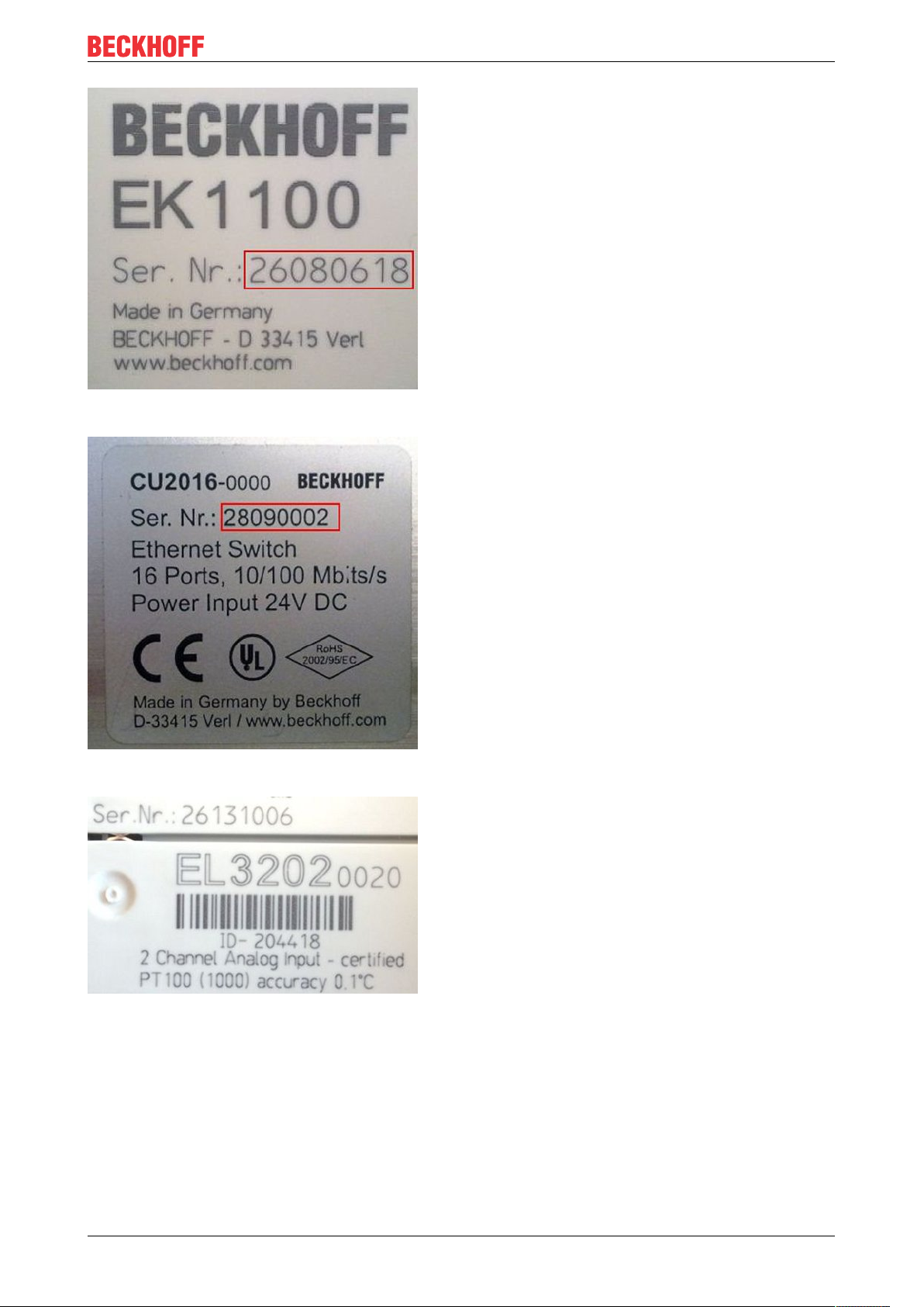
Fig.2: EK1100 EtherCAT coupler, standard IP20 IO device with serial/ batch number
Foreword
Fig.3: CU2016 switch with serial/ batch number
Fig.4: EL3202-0020 with serial/ batch number 26131006 and unique ID-number 204418
EK9500 9Version: 1.1.1
Page 10
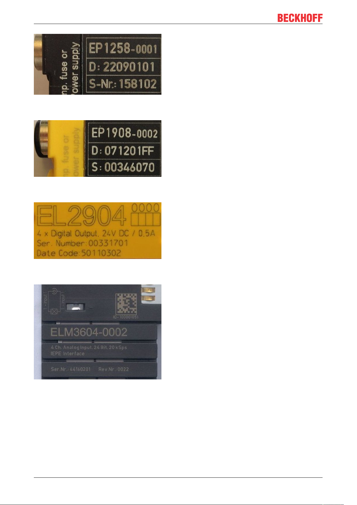
Foreword
Fig.5: EP1258-00001 IP67 EtherCAT Box with batch number/ date code 22090101 and unique serial
number 158102
Fig.6: EP1908-0002 IP67 EtherCAT Safety Box with batch number/ date code 071201FF and unique serial
number 00346070
Fig.7: EL2904 IP20 safety terminal with batch number/ date code 50110302 and unique serial number
00331701
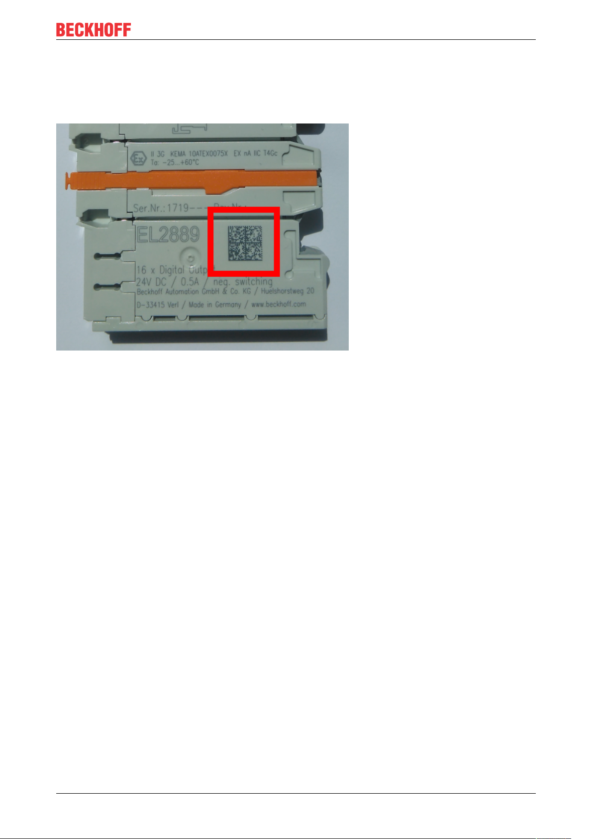
Fig.8: ELM3604-0002 terminal with unique ID number (QR code) 100001051 and serial/ batch number
44160201
EK950010 Version: 1.1.1
Page 11
Foreword
1.4.1 Beckhoff Identification Code (BIC)
The Beckhoff Identification Code (BIC) is increasingly being applied to Beckhoff products to uniquely identify
the product. The BIC is represented as a Data Matrix Code (DMC, code scheme ECC200), the content is
based on the ANSI standard MH10.8.2-2016.
Fig.9: BIC as data matrix code (DMC, code scheme ECC200)
The BIC will be introduced step by step across all product groups.
Depending on the product, it can be found in the following places:
• on the packaging unit
• directly on the product (if space suffices)
• on the packaging unit and the product
The BIC is machine-readable and contains information that can also be used by the customer for handling
and product management.
Each piece of information can be uniquely identified using the so-called data identifier
(ANSIMH10.8.2-2016). The data identifier is followed by a character string. Both together have a maximum
length according to the table below. If the information is shorter, spaces are added to it. The data under
positions 1 to 4 are always available.
The following information is contained:
EK9500 11Version: 1.1.1
Page 12

Foreword
Item
Type of
no.
information
1 Beckhoff order
number
2 Beckhoff Traceability
Number (BTN)
3 Article description Beckhoff article
4 Quantity Quantity in packaging
5 Batch number Optional: Year and week
6 ID/serial number Optional: Present-day
7 Variant number Optional: Product variant
...
Explanation Data
Beckhoff order number 1P 8 1P072222
Unique serial number,
see note below
description, e.g.
EL1008
unit, e.g. 1, 10, etc.
of production
serial number system,
e.g. with safety products
number on the basis of
standard products
Number of digits
identifier
S 12 SBTNk4p562d7
1K 32 1KEL1809
Q 6 Q1
2P 14 2P401503180016
51S 12 51S678294104
30P 32 30PF971, 2*K183
incl. data identifier
Example
Further types of information and data identifiers are used by Beckhoff and serve internal processes.
Structure of the BIC
Example of composite information from item 1 to 4 and 6. The data identifiers are marked in red for better
display:
BTN
An important component of the BIC is the Beckhoff Traceability Number (BTN, item no.2). The BTN is a
unique serial number consisting of eight characters that will replace all other serial number systems at
Beckhoff in the long term (e.g. batch designations on IO components, previous serial number range for
safety products, etc.). The BTN will also be introduced step by step, so it may happen that the BTN is not yet
coded in the BIC.
NOTE
This information has been carefully prepared. However, the procedure described is constantly being further
developed. We reserve the right to revise and change procedures and documentation at any time and without prior notice. No claims for changes can be made from the information, illustrations and descriptions in
this information.
EK950012 Version: 1.1.1
Page 13
2 Product overview
2.1 EKxxxx - System overview
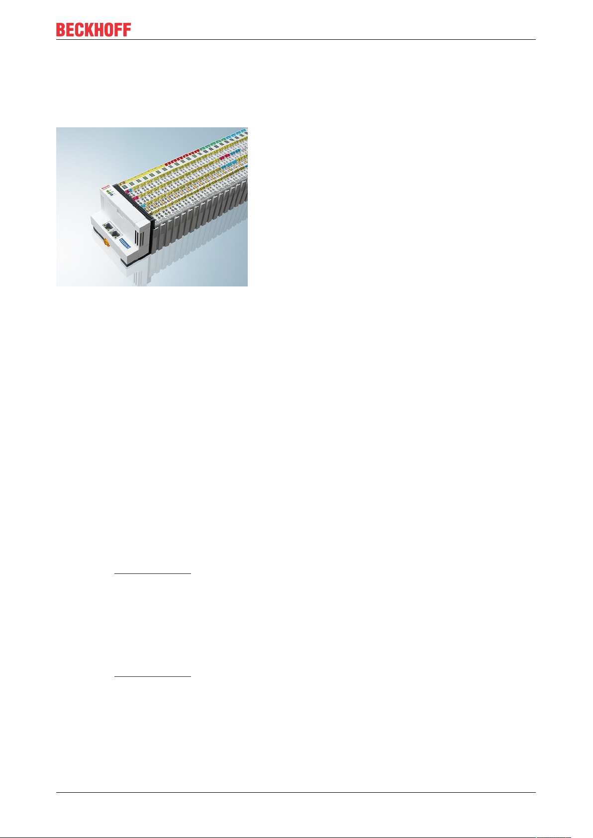
Fig.10: EtherCAT Terminals at an EKxxxx series Bus Coupler
Product overview
The Bus Couplers from the EKxxxx series allow EtherCAT Terminals to be operated on conventional fieldbus
systems. The ultra-fast, high-performance EtherCAT Terminals with their large range of signal types are thus
also available for other fieldbus and Industrial Ethernet systems.
The EKxxxx Bus Couplers are fieldbus slaves and contain an EtherCAT master for the EtherCAT terminals.
They convert the telegrams from the higher-level fieldbus systems into the E-bus signal representation. A
station consists of an EKxxxx and a number of EtherCAT Terminals.
The EKxxxx is integrated in exactly the same way as the Bus Couplers from the BKxxxx series via the
corresponding fieldbus system configuration tools and the associated configuration files, such as GSD, ESD
or GSDML.
EtherCAT makes a very flexible topology configuration possible. Thanks to the Ethernet physics, long
distances can also be bridged without the bus speed being affected. When changing to the field level –
without a control cabinet – the EtherCAT Box modules (EPxxxx) in protection class IP65 can also be
connected to the EK9xxx.
Bus Couplers for various fieldbus systems
The variants from the EKxxxx series differ from one another by the interface for the higher-level fieldbus
system.
An overview of the various Beckhoff Bus Couplers covering the most important fieldbus systems can be
found on the Beckhoff Website.
Embedded PCs with fieldbus interface and decentralized control
The TwinCAT-programmable variant is the CX80xx Embedded PC series.
The variants from the CX80xx series differ from one another by the interface for the higher-level fieldbus
system and the possibility to program it.
An overview of the various Beckhoff Embedded PCs covering the most important fieldbus systems can be
found on the Beckhoff Website.
EK9500 13Version: 1.1.1
Page 14
Product overview
2.2 EK9500 - Introduction
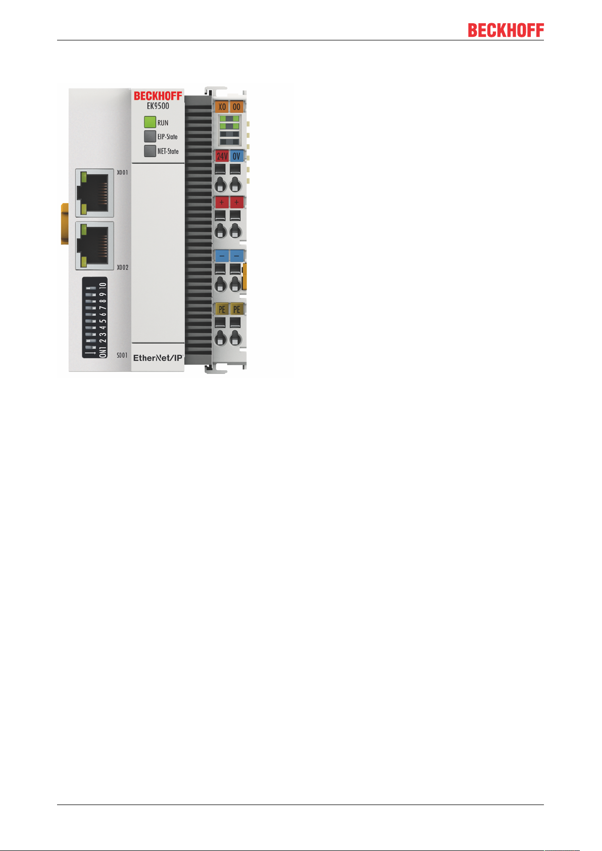
Fig.11: EK9500
The EK9500 Bus Coupler connects Ethernet/IP networks with the EtherCAT Terminals (ELxxxx) and
EtherCAT Box modules (EPxxxx) and converts the telegrams from Ethernet/IP to E-bus signal
representation.
One station consists of an EK9500 and EtherCAT Terminals. RJ45 is used for the Ethernet/IP connection. In
EtherCAT, the Ethernet/IP coupler has at its disposal a lower-level, powerful and ultra-fast I/O system with a
large selection of terminals. The coupler supports the EtherNet/IP protocol and therefore fits seamlessly into
Ethernet/IP networks.
Configuration
The EK9500 is configured based on HTML pages provided by the Bus Coupler or via the EtherNet/IP
interface.
EK950014 Version: 1.1.1
Page 15

Product overview
2.3 Technical data
Technical data EK9500
Protocol EtherNet/IP
Interfaces 2 x Ethernet 100 Mbit/s, 1 x USB device (behind the front flap)
Bus interface 2 x RJ 45 (switched)
I/O connection E-Bus (EtherCAT terminals)
Web-based Management yes
I/O terminals E-bus (EL, ES, EP), standard digital signals, standard analog
signals
No gateway EC terminals, no EC terminals with XFC or DC
function, no general EtherCAT devices
Number of EC terminals max. 255
Max. size of process data 496 bytes input and 496 bytes output data
Supply voltage 24VDC (-15%/+20%)
Power supply I/O terminals 2A
Max. power loss 3 W
Power contacts 24VDC max./10A max.
Electrical isolation 500V (power contact/supply voltage/Ethernet)
Dimensions (W x H x L) 64mm x 100mm x 80mm
Operating/storage temperature
horizontal mounting position
Operating/storage temperature
other mounting position
-25°C … +60°C/-40°C … +85°C
see note!
0…+55°C/-25…+85°C
see note!
*)
*)
Relative humidity 95 % no condensation
Vibration/shock resistance conforms to EN 60068-2-6 / EN 60068-2-27
EMC immunity/emission conforms to EN 61000-6-2 / EN 61000-6-4
Protect. class / installation pos. IP20/any
Approvals
CE, cULus [}25], ATEX [}26], EAC
1)
1) The acyclic communication via GetAttributeSingle/SetAttributeSingle can be used to read and write >
1000bytes.
E-Bus current/mounting positions
*)
- for -25°C..+60°C only horizontal mounting position, E-bus current 1 A max.
- for 0...+55°C mounting position any, E-bus current 2 A max.
System data Ethernet/IP (EK9500)
Number of I/O modules depending on controller
Number of I/O points depending on controller
Transmission medium 4 x 2 twisted pair copper cable category 5 (100 Mbit/s)
Cable length 100m
Data transfer rate 100 Mbit/s
Topology Star-form cabling, line topology
EK9500 15Version: 1.1.1
Page 16
Mounting and wiring
3 Mounting and wiring
3.1 Mounting
3.1.1 Instructions for ESD protection
NOTE
Destruction of the devices by electrostatic discharge possible!
The devices contain components at risk from electrostatic discharge caused by improper handling.
• Please ensure you are electrostatically discharged and avoid touching the contacts of the device directly.
• Avoid contact with highly insulating materials (synthetic fibers, plastic film etc.).
• Surroundings (working place, packaging and personnel) should by grounded probably, when handling
with the devices.
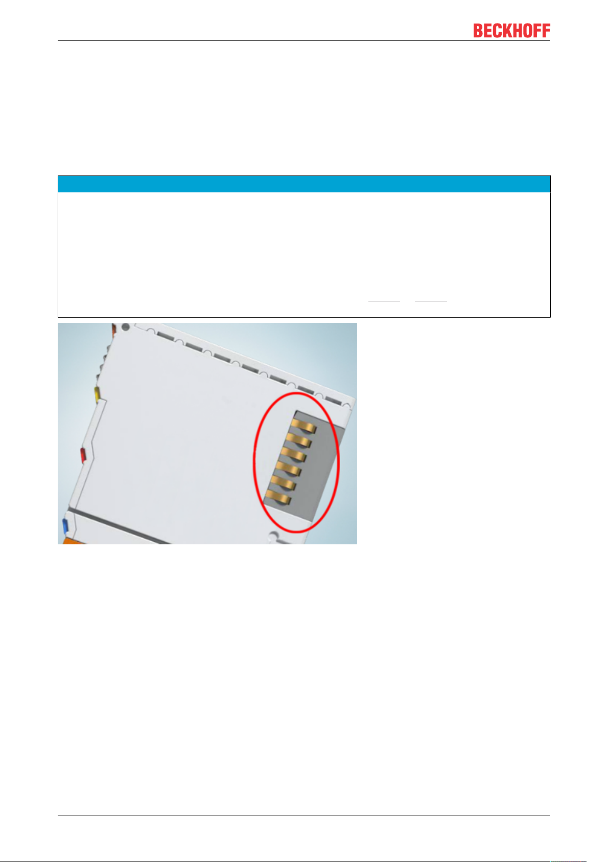
• Each assembly must be terminated at the right hand end with an EL9011 or EL9012 bus end cap, to ensure the protection class and ESD protection.
Fig.12: Spring contacts of the Beckhoff I/O components
EK950016 Version: 1.1.1
Page 17
Mounting and wiring
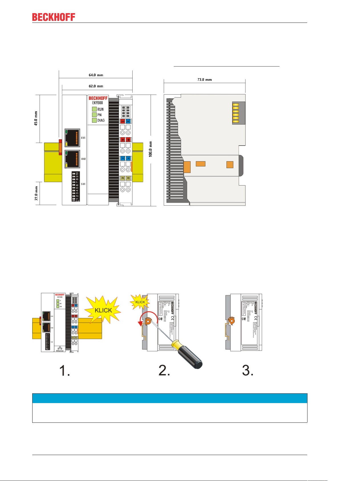
3.1.2 Dimensions
The following illustrations show the dimensions of the Bus Couplers.
Drawings in DWF and STEP format can be found in the Download section of the Beckhoff website.
Fig.13: EK9xxx – dimensions taking the EK9300 as an example
3.1.3 Installation on mounting rails – Bus Coupler
Snapping onto the mounting rail
The Bus Coupler can simply be snapped onto the mounting rail. To this end position the block on the
mounting rail and push it slightly until it engages on the right-hand side. This is indicated by a distinct click.
Use a screwdriver to push up the lock on the left-hand side, thereby turning it and causing it to engage
audibly.
Fig.14: EK9300 - Snapping onto the mounting rail
NOTE
Avoid damage!
Do not force the module or apply excessive pressure!
EK9500 17Version: 1.1.1
Page 18
Mounting and wiring
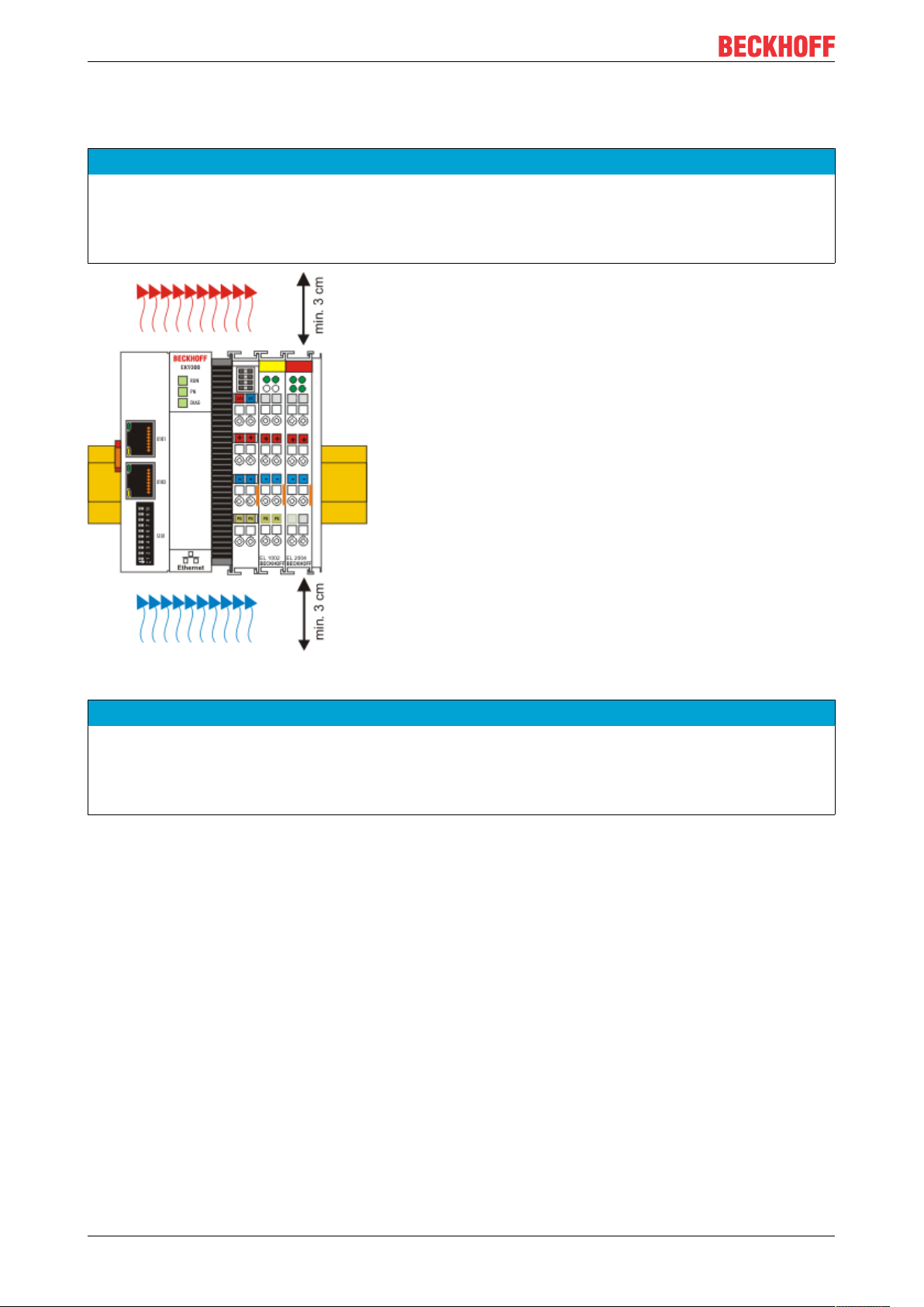
Installation positions
The installation position of the Bus Coupler is arbitrary.
NOTE
Installation position of EtherCAT terminals
Observe the installation position of the EtherCAT terminals used – not all of them have an arbitrary installation position. Pay attention to the respective EtherCAT infrastructure components and installation instructions.
Fig.15: Recommended distances for standard installation position
NOTE
Comply with the permitted installation position and minimum distances!
We recommend the installation in the horizontal position for optimum ventilation. Furthermore, it is not necessary with this installation position to check whether there are terminals present that may only be installed
horizontally.
Other installation positions are allowed, but not recommended.
EK950018 Version: 1.1.1
Page 19

Mounting and wiring
Fig.16: Other installation positions
3.2 Wiring
3.2.1 Power supply
The power supply unit is equipped with an I/O interface, which permits connection of the Beckhoff Bus
Terminals. The power is supplied via the upper spring-loaded terminals with the designations "24V and
"0V".
The supply voltage supplies the EK system and, via the terminal bus, the Bus Terminals with a voltage of 24
VDC (-15%/+20%). The dielectric strength of the power supply is 500 V. Since the terminal bus (E-bus) only
transfers data, a separate power supply is required for the Bus Terminals. This is provided by means of the
power contacts, which are not connected to the power supply.
EK9500 19Version: 1.1.1
Page 20

Mounting and wiring
Fig.17: Bus Coupler EK9xxx power supply
Requirements for the 24 V power supply
In order to guarantee the operation of the Bus Coupler and the terminal segment in all cases, the power
supply unit must supply 2.0 A at 24 V.
LED
If the power supply unit is connected correctly and the power supply is switched on, the two upper LEDs in
the terminal prism are green. The left LED (Us) indicates the CPU supply. The right LED (Up) indicates the
terminal supply. The other LEDs indicate the Terminal Bus status. A detailed description of the LEDs can be
found in section "LED troubleshooting".
PE power contacts
NOTE
Power contact “PE”
The "PE" power contact must not be used for other potentials.
EK950020 Version: 1.1.1
Page 21

3.2.2 Ethernet
3.2.2.1 Ethernet connections
Fig.18: RJ45 interface
Assignment of the RJ45 interface, port (switched)
EK9xxx: X001/ X002
PIN Signal Description
1 TD + Transmit +
2 TD - Transmit 3 RD + Receive +
4 connected reserved
5
6 RD - Receive 7 connected reserved
8
Mounting and wiring
EK9500 21Version: 1.1.1
Page 22

Mounting and wiring
3.2.2.2 Ethernet cable
Transmission standards
10Base5
The transmission medium for 10Base5 consists of a thick coaxial cable ("yellow cable") with a max.
transmission speed of 10Mbit/s arranged in a line topology with branches (drops) each of which is
connected to one network device. Because all the devices are in this case connected to a common
transmission medium, it is inevitable that collisions occur often in 10Base5.
10Base2
10Base2 (Cheaper net) is a further development of 10Base5, and has the advantage that the coaxial cable is
cheaper and, being more flexible, is easier to lay. It is possible for several devices to be connected to one
10Base2 cable. It is frequent for branches from a 10Base5 backbone to be implemented in 10Base2.
10BaseT
Describes a twisted pair cable for 10Mbit/s. The network here is constructed as a star. It is no longer the
case that every device is attached to the same medium. This means that a broken cable no longer results in
failure of the entire network. The use of switches as star couplers enables collisions to be reduced. Using
full-duplex connections they can even be entirely avoided.
100BaseT
Twisted pair cable for 100Mbit/s. It is necessary to use a higher cable quality and to employ appropriate
hubs or switches in order to achieve the higher data rate.
10BaseF
The 10BaseF standard describes several optical fiber versions.
EK950022 Version: 1.1.1
Page 23

Mounting and wiring
Short description of the 10BaseT and 100BaseT cable types
Twisted-pair copper cable for star topologies, where the distance between two devices may not exceed 100
meters.
UTP
Unshielded twisted pair
This type of cable belongs to category 3, and is not recommended for use in an industrial environment.
S/UTP
Screened/unshielded twisted pair (screened with copper braid)
Has an overall shield of copper braid to reduce influence of external interference. This cable is
recommended for use with Bus Couplers.
FTP
Foiled shielded twisted pair (screened with aluminum foil)
This cable has an overall shield of laminated aluminum and plastic foil.
S/FTP
Screened/foiled-shielded twisted pair (screened with copper braid and aluminum foil)
Has a laminated aluminum screen with a copper braid on top. Such cables can provide up to 70dB reduction
in interference power.
STP
Shielded twisted pair
Describes a cable with an outer screen, without defining the nature of the screen any more closely.
S/STP
Screened/shielded twisted pair (wires are individually screened)
This identification refers to a cable with a shield for each of the two wires as well as an overall shield.
ITP
Industrial Twisted-Pair
The structure is similar to that of S/STP, but, in contrast to S/STP, it has only one pair of conductors.
EK9500 23Version: 1.1.1
Page 24

Mounting and wiring
3.2.2.3 EK9500 Ethernet/IP topology sample
EK9500
The construction of the EK9500 can take place in a line, with adherence to the following points:
- Maximum 20 couplers one behind the other
- No switches should be usedin the line
Fig.19: Ethernet/IP topology
EK950024 Version: 1.1.1
Page 25

Mounting and wiring
3.3 UL notice
Application
Beckhoff EtherCAT modules are intended for use with Beckhoff’s UL Listed EtherCAT System only.
Examination
For cULus examination, the Beckhoff I/O System has only been investigated for risk of fire
and electrical shock (in accordance with UL508 and CSAC22.2 No.142).
For devices with Ethernet connectors
Not for connection to telecommunication circuits.
Basic principles
UL certification according to UL508 with limited power consumption. The current consumed by the device is
limited to a max. possible current consumption of 4A. Devices with this kind of certification are marked by
this sign:
Application
If terminals certified with restrictions are used, then the current consumption at 24VDC must be limited
accordingly by means of supply
• from an isolated source protected by a fuse of max. 4A (according to UL248) or
• from a voltage supply complying with NECclass2.
A voltage source complying with NECclass2 may not be connected in series or parallel with another
NECclass2compliant voltage supply!
These requirements apply to the supply of all EtherCAT bus couplers, power adaptor terminals, Bus
Terminals and their power contacts.
EK9500 25Version: 1.1.1
Page 26

Mounting and wiring
3.4 ATEX - Special conditions (standard temperature range)
WARNING
Observe the special conditions for the intended use of Beckhoff fieldbus components with
standard temperature range in potentially explosive areas (directive 2014/34/EU)!
• The certified components are to be installed in a suitable housing that guarantees a protection class of at
least IP54 in accordance with EN60079-15! The environmental conditions during use are thereby to be
taken into account!
• For dust (only the fieldbus components of certificate no. KEMA 10ATEX0075 X Issue 9): The equipment
shall be installed in a suitable enclosure providing a degree of protection of IP54 according to EN
60079-0 for group IIIA or IIIB and IP6X for group IIIC, taking into account the environmental conditions
under which the equipment is used.
• If the temperatures during rated operation are higher than 70°C at the feed-in points of cables, lines or
pipes, or higher than 80°C at the wire branching points, then cables must be selected whose temperature data correspond to the actual measured temperature values!
• Observe the permissible ambient temperature range of 0 to 55°C for the use of Beckhoff fieldbus components standard temperature range in potentially explosive areas!
• Measures must be taken to protect against the rated operating voltage being exceeded by more than
40% due to short-term interference voltages!
• The individual terminals may only be unplugged or removed from the Bus Terminal system if the supply
voltage has been switched off or if a non-explosive atmosphere is ensured!
• The connections of the certified components may only be connected or disconnected if the supply voltage has been switched off or if a non-explosive atmosphere is ensured!
• The fuses of the KL92xx/EL92xx power feed terminals may only be exchanged if the supply voltage has
been switched off or if a non-explosive atmosphere is ensured!
• Address selectors and ID switches may only be adjusted if the supply voltage has been switched off or if
a non-explosive atmosphere is ensured!
Standards
The fundamental health and safety requirements are fulfilled by compliance with the following standards:
• EN 60079-0:2012+A11:2013
• EN 60079-15:2010
• EN 60079-31:2013 (only for certificate no. KEMA 10ATEX0075 X Issue 9)
EK950026 Version: 1.1.1
Page 27

Mounting and wiring
Marking
The Beckhoff fieldbus components with standard temperature range certified according to the ATEX directive
for potentially explosive areas bear one of the following markings:
II 3GKEMA 10ATEX0075 X Ex nA IIC T4 GcTa: 0…+55°C
II 3D KEMA 10ATEX0075 X Ex tc IIC T135°C Dc Ta: 0 ... +55°C
(only for fieldbus components of certificate no. KEMA 10ATEX0075 X Issue 9)
or
II 3G KEMA 10ATEX0075 X Ex nC IIC T4 Gc Ta: 0 … +55°C
II 3D KEMA 10ATEX0075 X Ex tc IIC T135°C Dc Ta: 0 ... +55°C
(only for fieldbus components of certificate no. KEMA 10ATEX0075 X Issue 9)
3.5 ATEX - Special conditions (extended temperature range)
WARNING
Observe the special conditions for the intended use of Beckhoff fieldbus components with
extended temperature range (ET) in potentially explosive areas (directive 2014/34/EU)!
• The certified components are to be installed in a suitable housing that guarantees a protection class of at
least IP54 in accordance with EN60079-15! The environmental conditions during use are thereby to be
taken into account!
• For dust (only the fieldbus components of certificate no. KEMA 10ATEX0075 X Issue 9): The equipment
shall be installed in a suitable enclosure providing a degree of protection of IP54 according to EN
60079-0 for group IIIA or IIIB and IP6X for group IIIC, taking into account the environmental conditions
under which the equipment is used.
• If the temperatures during rated operation are higher than 70°C at the feed-in points of cables, lines or
pipes, or higher than 80°C at the wire branching points, then cables must be selected whose temperature data correspond to the actual measured temperature values!
• Observe the permissible ambient temperature range of -25 to 60°C for the use of Beckhoff fieldbus components with extended temperature range (ET) in potentially explosive areas!
• Measures must be taken to protect against the rated operating voltage being exceeded by more than
40% due to short-term interference voltages!
• The individual terminals may only be unplugged or removed from the Bus Terminal system if the supply
voltage has been switched off or if a non-explosive atmosphere is ensured!
• The connections of the certified components may only be connected or disconnected if the supply voltage has been switched off or if a non-explosive atmosphere is ensured!
• The fuses of the KL92xx/EL92xx power feed terminals may only be exchanged if the supply voltage has
been switched off or if a non-explosive atmosphere is ensured!
• Address selectors and ID switches may only be adjusted if the supply voltage has been switched off or if
a non-explosive atmosphere is ensured!
Standards
The fundamental health and safety requirements are fulfilled by compliance with the following standards:
• EN 60079-0:2012+A11:2013
• EN 60079-15:2010
• EN 60079-31:2013 (only for certificate no. KEMA 10ATEX0075 X Issue 9)
EK9500 27Version: 1.1.1
Page 28

Mounting and wiring
Marking
The Beckhoff fieldbus components with extended temperature range (ET) certified according to the ATEX
directive for potentially explosive areas bear the following marking:
II 3G KEMA 10ATEX0075 X Ex nA IIC T4 Gc Ta: -25 … +60°C
II 3D KEMA 10ATEX0075 X Ex tc IIC T135°C Dc Ta: -25 ... +60°C
(only for fieldbus components of certificate no. KEMA 10ATEX0075 X Issue 9)
or
II 3G KEMA 10ATEX0075 X Ex nC IIC T4 Gc Ta: -25 … +60°C
II 3D KEMA 10ATEX0075 X Ex tc IIC T135°C Dc Ta: -25 ... +60°C
(only for fieldbus components of certificate no. KEMA 10ATEX0075 X Issue 9)
3.6 Continuative documentation about explosion protection
Explosion protection for terminal systems
Pay also attention to the continuative documentation
Notes on the use of the Beckhoff terminal systems in hazardous areas according to ATEX and
IECEx
that is available for download on the Beckhoff homepage https:\\www.beckhoff.com!
EK950028 Version: 1.1.1
Page 29
Parameterization and commissioning
4 Parameterization and commissioning
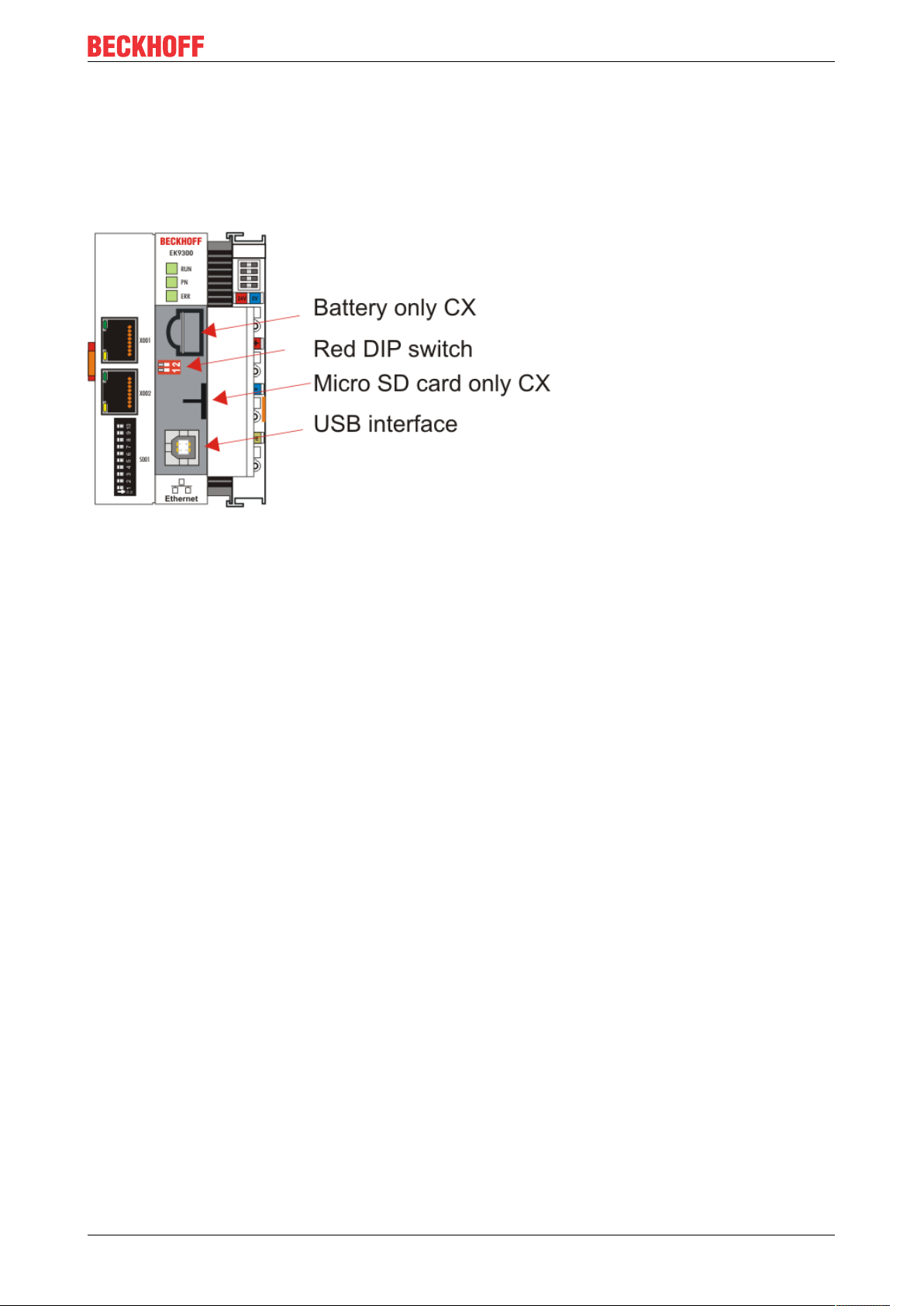
4.1 Further interfaces
Additional interfaces are located under the flap of the EK9xx0.
Fig.20: Additional interfaces of the EK9xx0
Battery
No battery is required for the EK9xx0, therefore this option is not included.
Red DIP switch
Default setting is OFF/OFF.
In order, for example, to load new firmware to the EK via USB, the first DIP switch must be set to “1” before
switching on. If the RUN LED lights up blue, the EK can be connected to the PC by a USB cable. The PC
then finds the internal Flash as the storage medium. The storage medium may not be formatted!
Micro SD card
Alternatively the firmware can also be loaded to an SD card. Booting always takes place from the SD card if
there is one in the slot. This can be used, for example, to test a firmware before copying it to the EK’s
internal Flash.
USB interface
The USB interface can only be used if the “red” DIP switch has been set accordingly. See “Red DIP switch”.
4.2 IP address
The IP address or the mode (e.g. DHCP) can be set using the DIP switch. Furthermore, an HTML page is
available for the configuration.
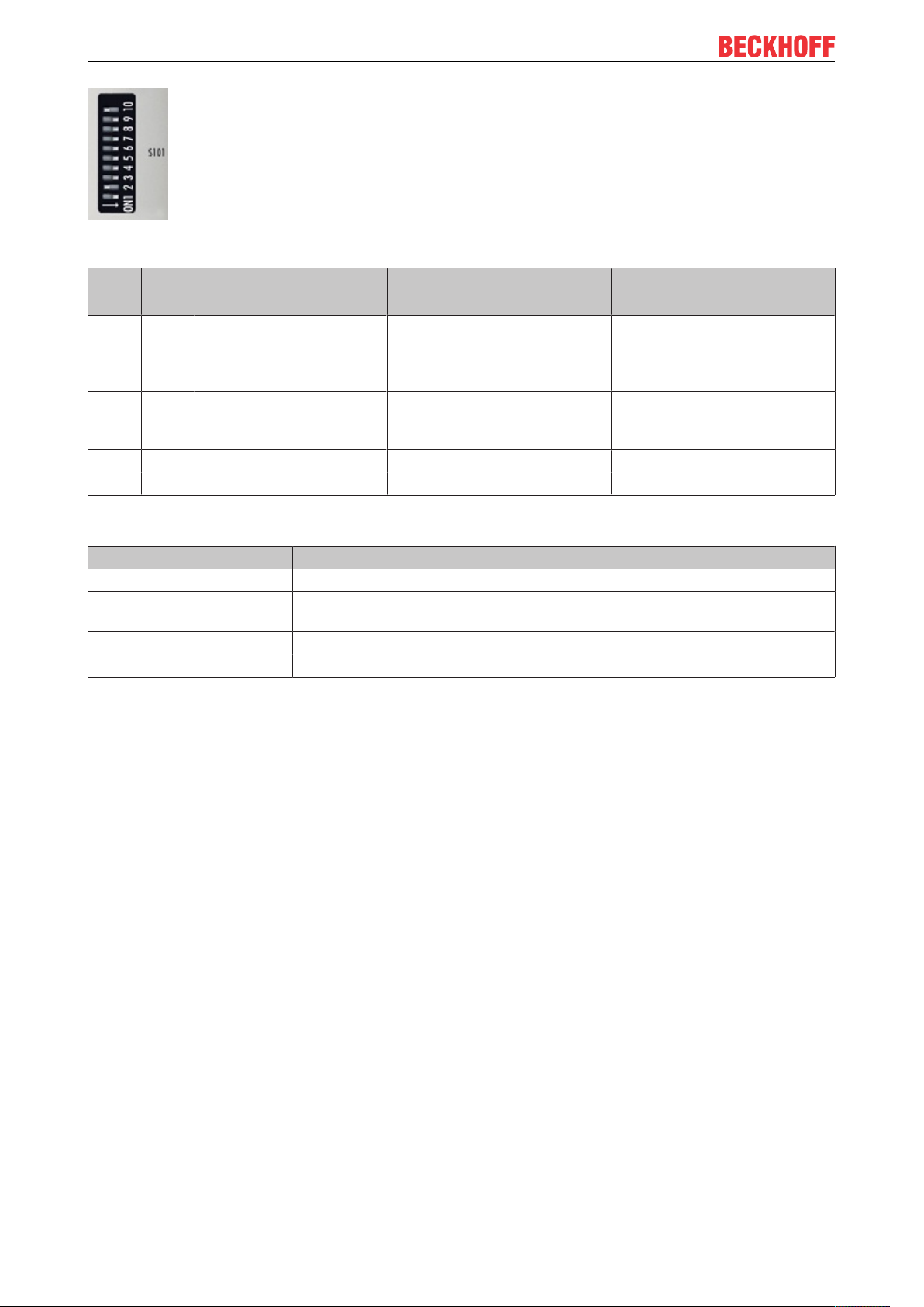
4.3 DIP switch
Ten-pole DIP switch S001
The DIP switch has the following meaning for the Ethernet interfaces X001 and X002, which are switched:
EK9500 29Version: 1.1.1
Page 30
Parameterization and commissioning
Fig.21: DIP switch S001: left off ”0“, right on “1”
DIP 9 DIP 10 Description
DIP 1..8
0 0 Last byte of the IP address
via DIP switches 1 to 8
0 1 DHCP
DIP switch 1 to 8 set to
OFF
1 0 Reserved - 1 1 Reserved - -
Two-pole DIP switch
DIP switch (red) Meaning
1 off and 2 off normal mode, coupler is started
1 on and 2 off The EK starts in Config Mode; the internal Flash memory can be accessed via
the USB interface (for example for an image update).
1 off and 2 on Factory setting
1 on and 2 on No function so far
Restart behavior Behavior with factory set-
tings
• IP address via DIP switch
(byte 4)
Bytes 1..3 from the setting
(Web page)
• IP address via DHCP • IP address via DHCP
• IP address via DIP switches
192.168.1.xxx (xxx DIP
switch)
SNM 255.255.255.0
EK950030 Version: 1.1.1
Page 31
Configuration
5 Configuration
5.1 Configuration via the HTML pages of the Bus Coupler
An HTML page is available for the configuration. This can be reached via the IP address/Config
(e.g.192.168.1.3/Config). We recommend the use of Chrome or Firefox as browser.
If DHCP is used, enter the name of the Bus Coupler instead of the IP address. The default name of the Bus
Coupler starts with the string "EK-", followed by the last 3 bytes of its MAC address (MAC ID). The MAC
address can be found on the sticker on the left of the Bus Coupler.
Sample: The MAC address is 00-01-05-02-03-04. The resulting default name is "EK-020304". Now enter
"EK-020304/Config" in your browser. The login name is "guest", the default password is "1" (without quotes).
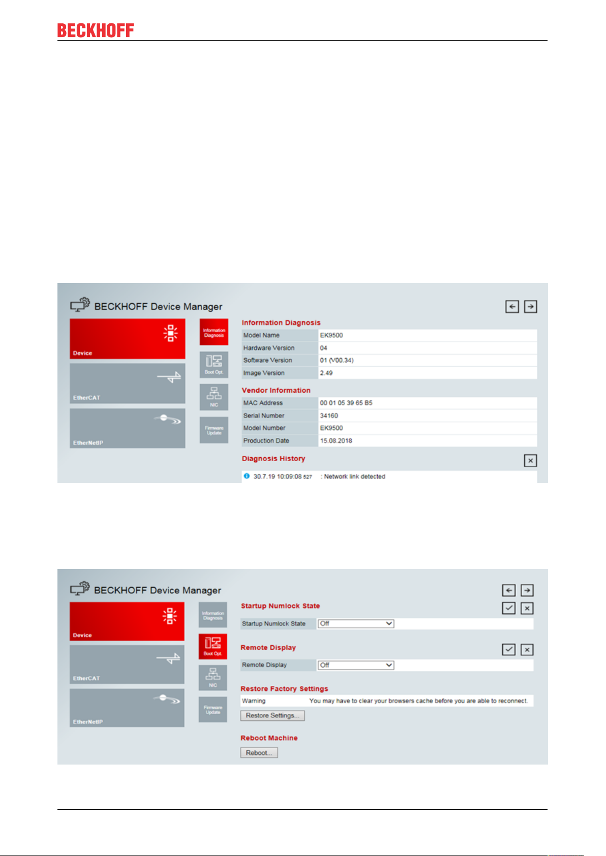
The firmware and hardware versions as well as the serial number can be read on the information diagnostic
page. The diagnosis history can be read if problems occur. The diagnosis history is not saved and is cleared
in the case of a restart.
Fig.22: Configuration via HTML pages - information diagnostic page
Boot Opt
The Boot Opt allows you to enable/disable Remote Display. You can also restore the factory settings and
trigger a manual reboot of the device.
Fig.23: Configuration via HTML pages – Boot Options
EK9500 31Version: 1.1.1
Page 32

Configuration
Network-Interface
The network interface enables you to set the IP address. Please note that the DIP switch of the EK9500
takes precedence and its setting applies regardless of what you set in the dialog
Fig.24: Configuration via HTML pages - network interface
Example
DIP switch DIP 1 = on; DIP 2...10 off, setting in the dialog 10.1.2.3 -> genuine IP address = 10.1.2.1 (The
DIP switch overwrites the last byte of the IP address).
Set the desired IP address and then click on the checkmark.
Note: the old IP address is displayed again in the dialog field since it is still the valid address.
A software reboot is necessary after changing the IP address. To do this, go onto "Boot Opt." and click on
"Reboot".
With the DIP switch setting
• DIP 1 to DIP 8 = on and
• DIP 9 and DIP 10 = off
all 4 bytes of the IP address are accepted from the dialog field.
Firmware Update
Is not used at this time.
5.2 EtherCAT configuration
EtherCAT Terminals can be configured and parameterized via the HTML page Beckhoff Device Manager.
EK950032 Version: 1.1.1
Page 33

Configuration
Fig.25: Configuration via HTML pages - EtherCAT configuration
EK9500 33Version: 1.1.1
Page 34

Configuration
Fig.26: Configuration via HTML pages - parameterizing EtherCAT Terminals
EtherCAT Master
The current state of the EtherCAT Master on the EK coupler is displayed here. It should usually be in the OP
state.
Network Statistics
The EtherCAT statistics are output here.
EtherCAT Slaves
Display of the EtherCAT slaves and their states. The Restore State indicates whether a Restore File has
been created for the terminals.
EK950034 Version: 1.1.1
Page 35

Configuration
Restore File
The Restore File is required in order to be able to parameterize EtherCAT Terminals again.
If EtherCAT Terminals are exchanged and have been parameterized, this information is usually lost when
the EtherCAT Terminal is exchanged. The Restore File loads the parameters to the new terminal when the
coupler is started. The Restore File has to be created if you want to change the default mapping of the
terminals.
• EMPTY
Means there is no Restore File for the terminal
• VALID
A valid Restore File has been created
• MAPPING
The terminal mapping has been changed, but has not yet been stored in a Restore File.
EtherCAT Slaves Mappings
In some EtherCAT Terminals, the process image can be changed; it must be stored in the EtherCAT master.
The terminals that can be changed are displayed under "EtherCAT Slaves Mapping"; the corresponding
mapping must be set and stored in the Restore file. The coupler is then restarted so that it can activate the
mapping (attention: the process image is changed as a result).
Fig.27: Configuration via HTML pages - EtherCAT slave mappings
Parameterization of the EtherCAT Terminals
To parameterize an EtherCAT Terminal, select the required terminal. Its objects are then displayed and can
be edited if necessary. The settings are then stored in the terminal. Note that any modifications are lost if the
terminal is replaced. In this case, use the restore file, which contains your modifications.
Restore file overwrites EtherNet/IP modifications
If the Restore File is used, the object parameters are always loaded into the terminal on starting the coupler.
This will overwrite changes that you have made via the web page.
5.3 EtherNet/IP Configuration
EtherNet/IP Slave:
EK9500 35Version: 1.1.1
Page 36

Configuration
Fig.28: Configuration via HTML pages – EtherNet/IP configuration
EtherNet/IP Device (Slave) - Device Info
All Parameters are “read only” and are for diagnostic purposes
EtherNet/IP Adapter (Slave) – Settings
• Error Confirmation Mode
EK950036 Version: 1.1.1
Page 37

Configuration
Select User Confirmation or Automatic Confirmation. Default Setting: User Confirmation
• Ebus Fallback mode
How the Coupler responds to a break in EtherCAT.
Set to Zero, Freeze, Stop Ebus. Default Setting: Set to Zero
• FBus Fallback Mode
How the Coupler responds to a break in the FBus.
Set to Zero, Freeze, Stop Ebus. Default Setting: Set to Zero
• TCP Timeout
Maximum time allowed for Ethernet Connection. Default Setting 30 Seconds
• Unicast TTL (Time To Live)
Used to determine if an Ethernet/IP Frame has been in the network too long and should be discarded
Default Setting 128 Seconds
• Unicast UDP Checksum
Enable/Disable UDP Checksum – Unicast (Frames sent to Single Destination). Checksum is a digit
representing the sum of the transmitted data used for error checking.
• Multicast TTL (Time to Live)
Used to determine if an Ethernet/IP Frame has been in the network too long and should be discarded
Default Setting 1 Second
• Multicast UDP Checksum
Enable/Disable UDP Checksum – Multicast (Copies of Frames sent to Multiple Destinations). Checksum is a
digit representing the sum of the transmitted data used for error checking.
Ethernet Statistics
Fig.29: EtherNet Statistics
Ethernet Rx Frames: Received Frames
Ethernet Tx Frames: Transmitted Frames
EK9500 37Version: 1.1.1
Page 38

Configuration
IP Stack Statistics
Fig.30: IP Stack Statistics
Ip Frames: A chunk of data sent over a data link
Arp Request: A request by the host wishing to obtain a physical address on a TCP/IP Network
Arp Reply: A unicast response to a broadcast request
Echo Request: Packets sent to a target host waiting for a reply
Echo Reply: Packets sent from a target host stating that it received the echo request
Link Status Changed: Indicates the number of times the state of the physical link has changed
Frame Alloc Fails: Indicates the number of Frame Allocation Fails
Arp Timeout Frames: The number of frames that were sent and not received back in time
Dropped Frames: Indicates the number of dropped frames
Electronic Data Sheet
Create EDS File: Create an Electronic Data Sheet for Use with an EIP Master
Create L5X File: Create UDTs for Input and Output Data (For use with RSLogix 5000 Import Only)
EK950038 Version: 1.1.1
Page 39

5.4 EtherNet/IP Mapping
Configuration
Fig.31: EtherNet/IP Mapping
Config Instance: 128
Input Instance: 129
Output Instance: 130
Byte Size refers to the size of the process image (Input and Output Data Configuration)
5.5 EK9500 - EtherCAT configurations
The EK9500 is an EtherCAT master with automatic configuration, i.e. all EtherCAT Terminals must always
be present when switching on the system. Since the boot-up of the EK9500 generally takes considerably
longer than the start-up of the EtherCAT slave devices, the latter can be operated on the same power
supply. With decentralized EtherCAT slaves, care must be taken that they are switched on earlier or at the
same time as the supply voltage..
Switching EtherCAT devices on or off during the runtime
If one or more EtherCAT devices should fail during the operating phase, an error response is generated. The
input data of all EtherCAT devices are then invalid and the output data are no longer accepted. This also
applies to the devices that are still in operation on the EK9500. If you wish to use the option to plug in or
unplug devices during the runtime, a further “Sync Unit” must be configured. This is not possible with an
EK9500. In this case, use a CX8090.
EtherCAT topology
All EtherCAT devices must be entered in the order in which they map themselves on the EK9500 and thus
on the EtherCAT master. EtherCAT devices are automatically addressed; with a few exceptions all EtherCAT
Bus Terminals are equipped with an EtherCAT ASIC. EtherCAT Terminals without an ASIC are, for example,
EK9500 39Version: 1.1.1
Page 40

Configuration
EL9400, EL9070 and other EL9xxx. You can identify these EtherCAT Terminals using the technical data
"Message to E-bus". If there is a "-" here, this terminal need not be taken into account for the mapping.
EtherCAT devices are registered in the direction of the EtherCAT telegram.
Sample configuration with EK1100 EtherCAT coupler
Fig.32: Sample configuration with EK1100 EtherCAT coupler
EK950040 Version: 1.1.1
Page 41

Sample configuration with EPxxxx EtherCAT Box
Configuration
Fig.33: Sample configuration with EPxxxx EtherCAT Box
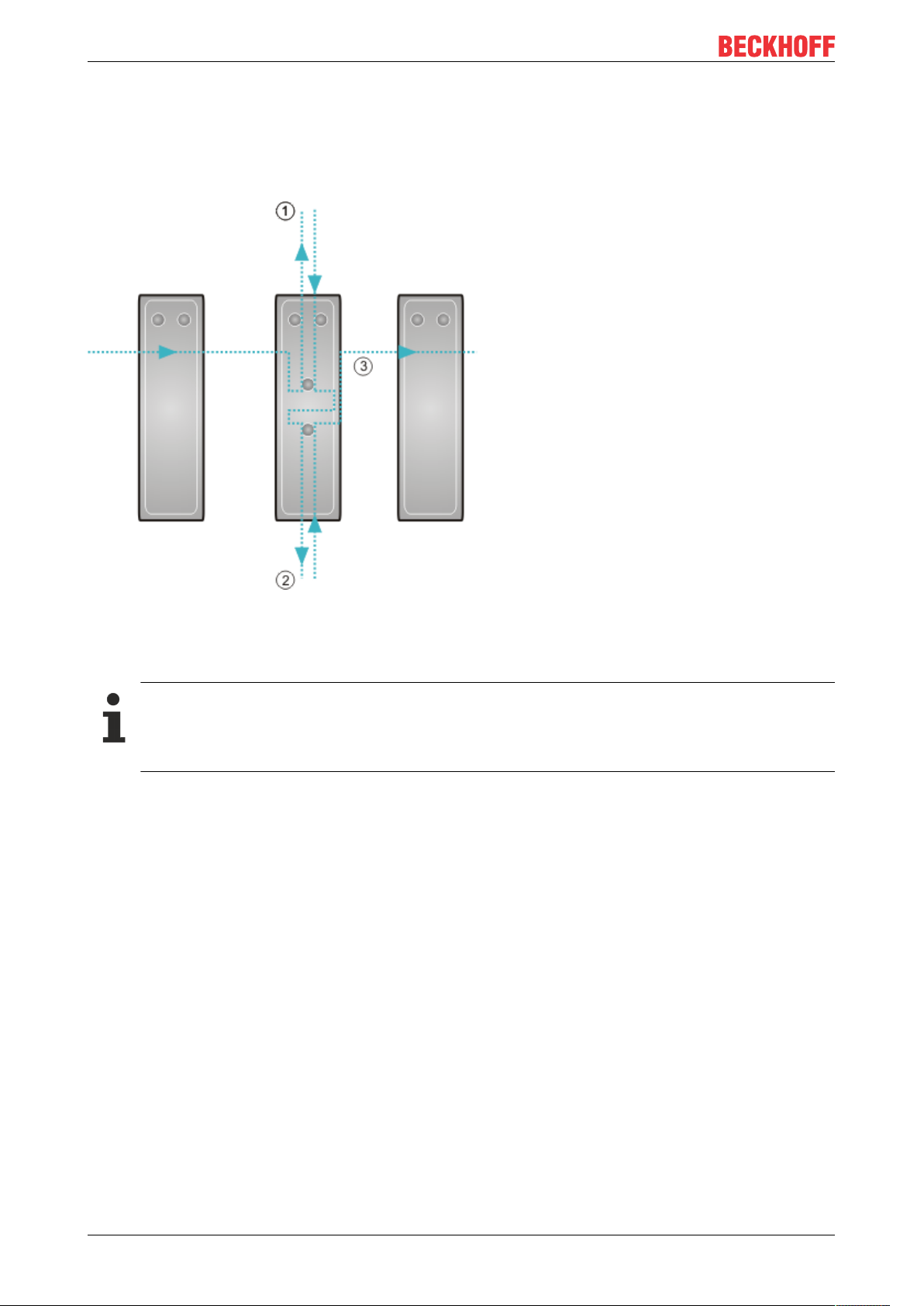
Sample configuration with EK1122 2-port EtherCAT junction
The counting direction is to be observed when using an EK1122.
If EtherCAT junction 1 on the EK1122 is connected, then the EtherCAT frame is forwarded here first (1); if
junction 1 is not connected the frame on junction 2 is sent (2), only after that does the sequence continue
with the E-bus on the right-hand side (3).
Fig.34: Sample configuration with EK1122 2-port EtherCAT junction
If neither junction is used, then junctions 1 and 2 are bridged, so to speak, and the EtherCAT frame goes
directly to the E-Bus on the right-hand side.
EK9500 41Version: 1.1.1
Page 42
Configuration
Example configuration with EP1122 (2-port EtherCAT junction in protection class IP65)
The counting direction is to be observed when using an EP1122! It is comparable with the EK1122.
If EtherCAT junction 1 on the EP1122 is connected, then the EtherCAT frame is forwarded here first (1); if
junction 1 is not connected, the frame on junction 2 is sent (2), only after that does the sequence continue
with the EtherCAT connection on the right-hand side (3).
Fig.35: Sample configuration with EP1122 (2-port EtherCAT junction in protection class IP65)
If neither junction is used, then junctions 1 and 2 are bridged, so to speak, and the EtherCAT frame goes
directly to the EtherCAT connection on the right-hand side.
No Hot Swap during operation
You cannot use the EP1122 and EK1122 on an EKxxxx for Hot Swap and also not for connection
and disconnection during operation. EP1122 and EK1122 are suitable only for topology extensions
(star) on an EKxxxx.
EK950042 Version: 1.1.1
Page 43
6 Error handling and diagnosis
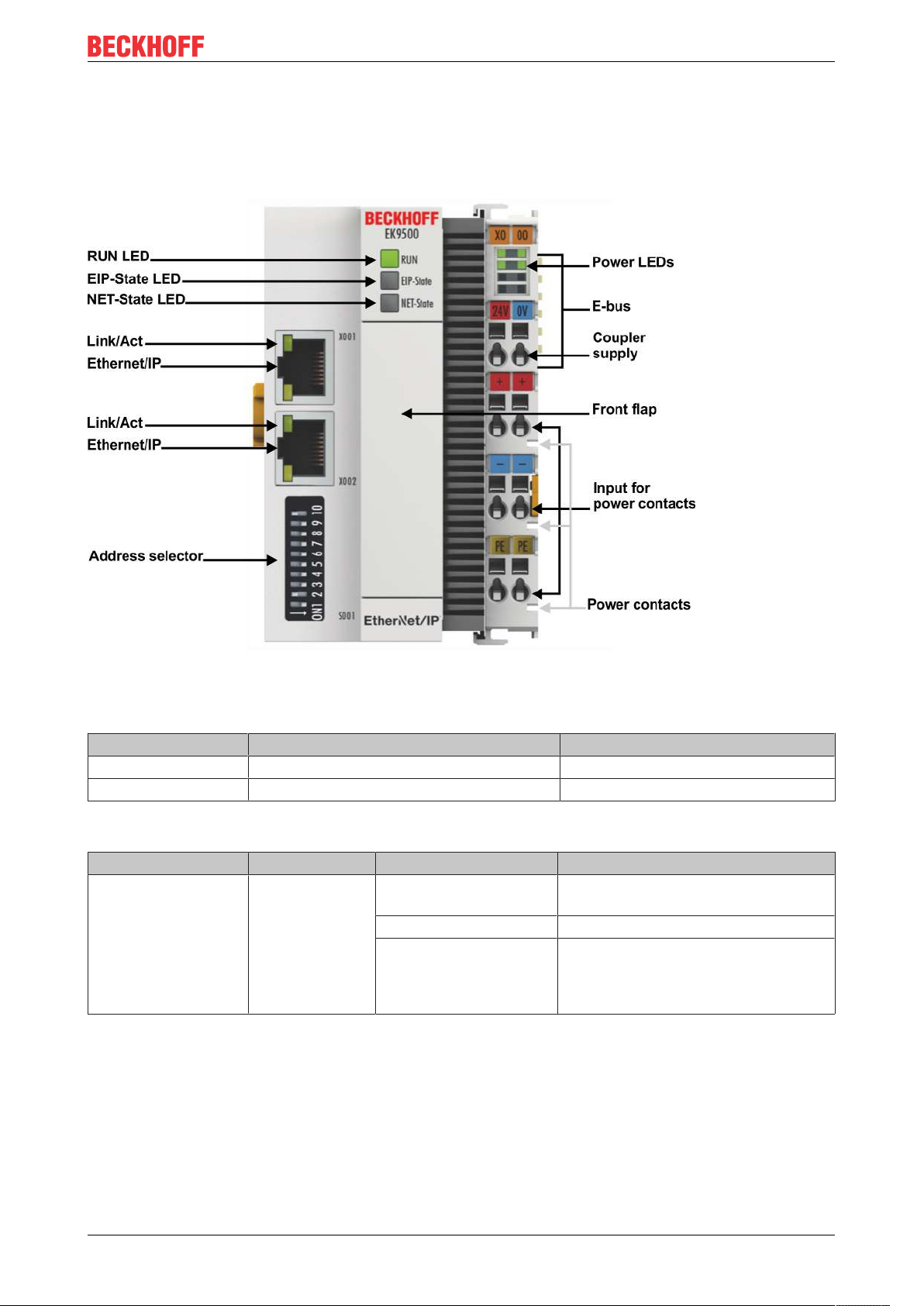
6.1 LED indicators
Error handling and diagnosis
Fig.36: EK9500 LEDs
Ethernet interface
Interface X001/X002 Ethernet Meaning
LED green On/flickering (blinking) Link available/activity
LED yellow is not used -
LED on the coupler
Labelling Meaning Color Meaning
RUN Indicates the
status of the
coupler
red May only light up during the start-up
phase
Green Coupler is ready
Blue
(If red DIP switch 1 is set
to on when starting the
coupler)
The internal Flash can be reached via
USB (firmware update)
EK9500 43Version: 1.1.1
Page 44

Error handling and diagnosis
LED EIP State
Color green Color red Meaning
on off The coupler is in data exchange with EhterNet/IP-Scanner (Master), cyclic
exchange of valid process data.
off (1s)
on (200ms)
flashes
(400ms)
off off (1s)
off on Internal error. Replace the coupler
LED NET State
Color green Color red Meaning
off off No link detected
on off Coupler has detected a link and was configured correctly
flashes
(400ms)
off (1s)
on (200ms)
off on Internal error. Replace the coupler
off off (1s)
off EtherNet/IP slave and IO assembly are correctly parameterized
off The EtherNet/IP slave has no valid IO assembly configuration
A general error occurred with the EtherNet/IP slave
on (200ms)
off The Ethernet port has an active link and the EtherNet/IP Slave interface has
no valid IP address.
off The EtherNet/I slave has a valid IP address. UDP and TCP Layer was
initialized
A general error occurred with the EtherNet/IP slave
on (200ms)
LEDs starting up
Run EIP State NET State Meaning
off off off No electrical voltage connected to E-bus. Coupler must be
exchanged if EtherCAT Terminals behind it need to function.
off off red LED is on and flashes a few times, after 3sec switch to off
BOOT load CPU
off off off 3..4 sec Firmware load
red off off 8 sec Firmware start
Red/green Yellow - Flashing fast: EtherCAT Scanning;
time: different (depending on the number and type of
EtherCAT participants)
Red/green Yellow - Flashing slow: EtherCAT COE reading;
time: different (depending on the number and type of
EtherCAT participants)
Green - - Start up is finished
EK950044 Version: 1.1.1
Page 45
Error handling and diagnosis
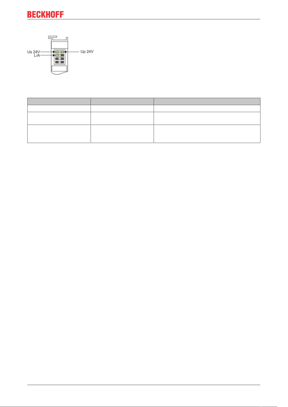
LEDs on power supply terminal
Fig.37: LEDs on power supply terminal
Operation with E-bus terminals
Display LED Description Meaning
1 Us 24 V (top left, 1st row) Supply voltage on: connected to: 24 V
2 Up 24V (top right, 1st row) Power contacts supply
voltage
3 L/A (left center, 2nd row) EtherCAT LED flashing green: EtherCAT communication active
on: connected to: 24 V
on: E-bus connected / no data traffic
off: E-bus not connected
EK9500 45Version: 1.1.1
Page 46

Appendix
7 Appendix
7.1 Update Bus Coupler image
Loss of data
The data in the internal flash memory are deleted.
Save your data before you update the Bus Coupler image.
The Bus Coupler image can be updated via the USB interface. To this end the Bus Coupler is connected
with a host PC via a USB cable. Windows then shows the Bus Coupler as a removable data storage device,
and the files can be copied.
The Bus Coupler should only be updated after consultation with the Beckhoff Service. The Beckhoff Service
will provide all the required files.
Requirements
• First, check whether the Bus Coupler supports the image.
• The Bus Coupler is connected with the host PC via a USB cable.
Update the image as follows:
1. Switch off the Bus Coupler.
2. Switch the red 2-pin DIP switch 1 to “on” (to the right) and switch on the Bus Coupler.
The Bus Coupler appears as a removable data storage device on the host PC.
3. Select and delete all files. Do not format.
4. Remove the USB cable, once all files have been copied, and switch the 2-pin DIP switch to “off” (to the
left).
5. Restart the Bus Coupler.
ð The image has been updated successfully. After the update, the Bus Coupler may take a little longer to
start up.
EK950046 Version: 1.1.1
Page 47
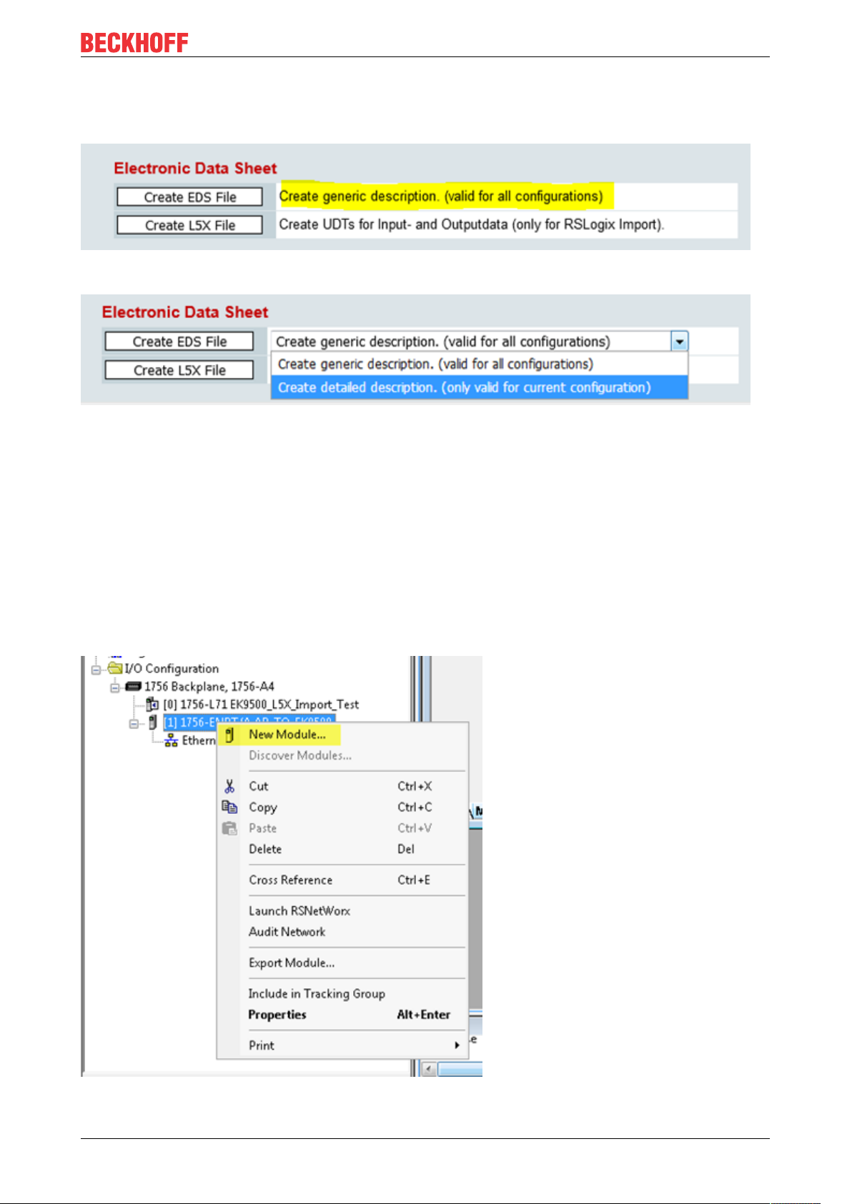
7.2 Setting up the EK9500 in RS Logix Studio 5000 via EDS File
Fig.38: Setting up the EK9500 in RS Logix Studio 5000 via EDS File - Create generic description
Fig.39: Setting up the EK9500 in RS Logix Studio 5000 via EDS File - Create detailed description
You can choose between
Appendix
• Create generic description (valid for all configuration) – using more than one coupler in your project
• Create detailed description (only valid for current configuration) – using only one coupler in your project
This is an example of how to set up the EK9500 in RS Logix Studio 5000 using the EDS File that can be
exported from the Device Manager:
Click on the “Create EDS File” button referenced above. This will create the EDS file that you can import into
the Rockwell Software. Once you have successfully imported the EDS file into the Rockwell software, most
of the configuration will be taken care of automatically.
Configure your Hardware as appropriate in RS Logix Studio 5000 and then add a “New Module”:
Fig.40: Add a new module in RS Logix 5000
EK9500 47Version: 1.1.1
Page 48

Appendix
Search for the EK9500 (This will only work after you have imported the EDS file):
Fig.41: Search for the EK9500 in RS Logix Studio 5000
Enter the IP Address that was configured for the EK9500 and then click on Change:
Fig.42: Set the IP Address of the EK9500 in RS Logix Studio 5000
Set the data size according to what is shown in the EIP Mapping [}39]:
EK950048 Version: 1.1.1
Page 49

Appendix
Fig.43: Set the Size of your Input and Output Instances in RS Logix Studio 5000
All of the Assembly Instance data is read from the EDS file (Input: 129, Output: 130, Config: 128). Once you
download the configuration and go online the communication will start up automatically.
Create L5X File
For RS Logix Studio it is possible to generate a data structure for in and output to get a easier mapping
information about the connected EtherCAT terminals or modules (“module-defined”).
7.3 Setting up an EK9500 as a Generic Device in RS Logix Studio 5000
Configure your Rockwell Hardware accordingly in RS Logix Studio 5000.
Then add a new Generic Module:
EK9500 49Version: 1.1.1
Page 50

Appendix
Fig.44: Add a Generic Module to your hardware configuration in RS Logix Studio 5000
Enter a name for your Generic Module (EK9500_1 in the example). Enter the IP Address that was set on the
EK9500. The Data type can be set to SINT, INT, DINT or any other optional data type as long as the total
number of BYTES is equal to what is shown in the Device Manager EtherNET/IP Mapping. Enter the
Assembly Instance Numbers (Input: 129, Output: 130, Config: 128). Click OK.
Fig.45: Configure the parameters for the Generic Module in RS Logix Studio 5000
In RS Logix Studio 5000, click to go online and download the configuration to the controller. Communication
between the Rockwell hardware and the EK9500 will start up automatically.
EK950050 Version: 1.1.1
Page 51

Appendix
7.4 Using the CtrlStatus DWORD
The CtrlStatus DWORD module is added automatically, it is for diagnosis information about the EtherCAT
(E-Bus) status. The CtrlStatus DWORD (4 bytes) has the following meaning:
Input CtrlStatus DWORD
Structure and meaning of the input CtrlStatus DWORD module.
Byte 3 Byte 2 Byte 1 Byte 0
Reserve Diag Counter High Byte Counter Low Byte
• Counter WORD (2 bytes):
The counter is an E-bus counter and is incremented with each E-bus telegram. By default, the E-bus
runs at 1 ms. Thus, the counter is incremented every ms. If bit 2 is set in the Diag byte, further
information about the error is included instead of the counter.
• DIAG BYTE (1 byte):
0x10 E-bus fixed after error. Outputs are disabled and have to be reset manually with the control
DWORD.
0x04 E-bus error. In the event of an E-bus error, the EK9500 Bus Coupler continues to exchange data
with the EtherNet/IP scanner (master). However, the input data are invalid. The cause of the error is
coded in the high byte, the position in the low byte of the counter.
Byte 1, error code counter Byte 0, counter Meaning
1 Terminal position Wrong module.
2 Missing module.
3 Module pulled.
4 Wrong module connected.
5 EtherCAT slave not in OP.
6 State change aborted.
7 Abnormal state change.
8 SDO-Abort
9 Wrong SDO length
10 Wrong SDO data.
Example:
Byte 1 0x03 interruption of the E-bus, byte 0 position of the interruption.
Output CtrlStatus DWORD
Structure and meaning of the output CtrlStatus DWORD module.
Byte 3 Byte 2 Byte 1 Byte 0
Reserve Reserve Reserve Control byte
Control byte (bit 0):
If bit 4 (0x10) is set in the DIAG BYTE, the controller can acknowledge the error. To this end, bit 0 (in the first
byte of the control DWORD) has to be set to “TRUE”, and the E-bus is restarted with a falling edge of bit 0.
The output process data are active again immediately.
7.5 Supported CIP objects
Identity Object
Class code : 0x01
EK9500 51Version: 1.1.1
Page 52

Appendix
There is one instance(=1) of this object in EK9500.
Class Attribute List
no class attributes implemented
Instance Attribute List
Attr ID Access
Rule
1 Get Vendor ID UINT (16) 106, the vendor ID of Beckhoff.
2 Get Device Type UINT (16) 12, communication adapter
3 Get Product
4 Get Revision (Struct.) Product revision
5 Get Status WORD (16) Not used
6 Get Serial
7 Get Product
The Identity Object Instance supports the following CIP Common services:
Common Service List
Service
Code
0x01 √ Get_Attributes_All Returns the contents of all attributes of the
0x0E √ Get_Attribute_Single Used to read an object instance attribute.
Implementation Service Name Description
Class Instance
Name (Struct.) Data Type Description
UINT (16) 9500
Code
Major USINT (8) The structure member, major
Minor USINT (8) The structure member, minor.
UDINT (32) The serial number of each device
Number
Name
SHORT_
STRING
“EK9500”
class
Assembly Object
Class code: 0x04
There are three instances of this object as the following.
Instance Number Size (byte)
Input
(only Get)
Output
(Get/Set)
Class Attribute List
no class attributes implemented
Instance Attribute List
Attr ID Access
3 Get/Set Data Array of
4 Get Size UINT (16) Number of bytes in Attr. 3
Common Service List
129 depending the amount and type of attached input terminals
130 depending the amount and type of attached output terminals
Name (Struct.) Data Type Description
Rule
The implicit messaging content
BYTE
EK950052 Version: 1.1.1
Page 53

Appendix
Service
Code
0x0E √ Get_Attribute_Single Used to read input and output process
0x10 √ Set_Attribute_Single Used to write output process data (only
Implementation Service Name Description
Class Instance
data (attr 3) or read process data length
(attr. 4)
possible if no class1 connection opened to
this assembly)
7.6 FAQ
How can I change the mapping of an EtherCAT Terminal?
Use the Web configuration for this and generate a Restore File.
How do I know what the MAC address of the Bus Coupler is?
The MAC address is printed on the label on the side of the Bus Coupler.
What is the USB interface for and what can I do with it?
The USB interface is to be used at present only for firmware updates.
What is the purpose of the DIP switch behind the flap?
It is necessary, for example, for the use of the firmware update (see chapter entitled "DIP switch").
Can I also operate K-bus terminals?
No, only EtherCAT terminals or EtherCAT boxes can be connected. You can use the BK9050 BK9055 or
BK91050 for K-bus terminals. The use of EtherCAT couplers for K-bus such as the BK1120 or BK1250 is
not possible.
I have an EtherCAT slave from a third-party vendor. Can I also connect it?
No, devices from other vendors can only be used with a CX (see CX8095 or similar products).
I would like to operate the drive terminals/drives on the EK9500. Is that possible?
No, use a CX with a suitable performance for this, e.g. CX9020 or higher.
Exception: if the terminals do not need TwinCAT PTP/NC. These are terminals with a position control
interface.
I would like to operate TwinSAFE terminals on the EK9500. Is that possible?
No, the TwinSAFE terminals require a TwinCAT system for configuration; use the CX8095 for this
How do I see that there is an EtherCAT error?
In this case, the ERR LED lights up red and in the Control/Status DWORD.
7.7 List of Abbreviations
ADS
Automation Device Specification (disclosed protocol for the communication of all BECKHOFF controllers)
DAP
Device Access Point
I/O
Inputs and outputs
EK9500 53Version: 1.1.1
Page 54

Appendix
E-bus
Designation for EtherCAT terminals in the terminal group (ELxxxx, ESxxxx, or EMxxxx)
EtherCAT
EtherCAT (Ethernet for Control Automation Technology) is the Ethernet solution for industrial automation,
characterized by outstanding performance and particularly simple handling.
Fast Ethernet
Data rate 100Mbits/s according to the 100Base-T standard.
IP20
Protection class of the Bus Terminals, EtherCAT Terminals
IPC
Industrial PC
K-bus
Terminal bus (KLxxxx, KMxxxx or KSxxxx terminals)
KS2000
Configuration software for Bus Terminals, Bus Couplers, Bus Terminal Controllers, fieldbus box modules,
etc.
PE
The PE power contact can be used as a protective earth.
TwinCAT
The Windows Control and Automation Technology, programmer and configuration tool from the BECKHOFF
Automation.
EK950054 Version: 1.1.1
Page 55

Appendix
7.8 Support and Service
Beckhoff and their partners around the world offer comprehensive support and service, making available fast
and competent assistance with all questions related to Beckhoff products and system solutions.
Beckhoff's branch offices and representatives
Please contact your Beckhoff branch office or representative for local support and service on Beckhoff
products!
The addresses of Beckhoff's branch offices and representatives round the world can be found on her internet
pages:
http://www.beckhoff.com
You will also find further documentation for Beckhoff components there.
Beckhoff Headquarters
Beckhoff Automation GmbH & Co. KG
Huelshorstweg 20
33415 Verl
Germany
Phone: +49 5246 963 0
Fax: +49 5246 963 198
e-mail: info@beckhoff.com
Beckhoff Support
Support offers you comprehensive technical assistance, helping you not only with the application of
individual Beckhoff products, but also with other, wide-ranging services:
• support
• design, programming and commissioning of complex automation systems
• and extensive training program for Beckhoff system components
Hotline: +49 5246 963 157
Fax: +49 5246 963 9157
e-mail: support@beckhoff.com
Beckhoff Service
The Beckhoff Service Center supports you in all matters of after-sales service:
• on-site service
• repair service
• spare parts service
• hotline service
Hotline: +49 5246 963 460
Fax: +49 5246 963 479
e-mail: service@beckhoff.com
EK9500 55Version: 1.1.1
Page 56

List of illustrations
List of illustrations
Fig. 1 EL5021 EL terminal, standard IP20 IO device with serial/ batch number and revision ID (since
2014/01)....................................................................................................................................... 8
Fig. 2 EK1100 EtherCAT coupler, standard IP20 IO device with serial/ batch number......................... 9
Fig. 3 CU2016 switch with serial/ batch number.................................................................................... 9
Fig. 4 EL3202-0020 with serial/ batch number 26131006 and unique ID-number 204418 ................... 9
Fig. 5 EP1258-00001 IP67 EtherCAT Box with batch number/ date code 22090101 and unique se-
rial number 158102...................................................................................................................... 10
Fig. 6 EP1908-0002 IP67 EtherCAT Safety Box with batch number/ date code 071201FF and
unique serial number 00346070 .................................................................................................. 10
Fig. 7 EL2904 IP20 safety terminal with batch number/ date code 50110302 and unique serial num-
ber 00331701............................................................................................................................... 10
Fig. 8 ELM3604-0002 terminal with unique ID number (QR code) 100001051 and serial/ batch num-
ber 44160201............................................................................................................................... 10
Fig. 9 BIC as data matrix code (DMC, code scheme ECC200)............................................................. 11
Fig. 10 EtherCAT Terminals at an EKxxxx series Bus Coupler............................................................... 13
Fig. 11 EK9500........................................................................................................................................ 14
Fig. 12 Spring contacts of the Beckhoff I/O components......................................................................... 16
Fig. 13 EK9xxx – dimensions taking the EK9300 as an example............................................................ 17
Fig. 14 EK9300 - Snapping onto the mounting rail.................................................................................. 17
Fig. 15 Recommended distances for standard installation position......................................................... 18
Fig. 16 Other installation positions........................................................................................................... 19
Fig. 17 Bus Coupler EK9xxx power supply.............................................................................................. 20
Fig. 18 RJ45 interface.............................................................................................................................. 21
Fig. 19 Ethernet/IP topology .................................................................................................................... 24
Fig. 20 Additional interfaces of the EK9xx0............................................................................................. 29
Fig. 21 DIP switch S001: left off ”0“, right on “1”...................................................................................... 30
Fig. 22 Configuration via HTML pages - information diagnostic page..................................................... 31
Fig. 23 Configuration via HTML pages – Boot Options ........................................................................... 31
Fig. 24 Configuration via HTML pages - network interface...................................................................... 32
Fig. 25 Configuration via HTML pages - EtherCAT configuration............................................................ 33
Fig. 26 Configuration via HTML pages - parameterizing EtherCAT Terminals........................................ 34
Fig. 27 Configuration via HTML pages - EtherCAT slave mappings ....................................................... 35
Fig. 28 Configuration via HTML pages – EtherNet/IP configuration........................................................ 36
Fig. 29 EtherNet Statistics ....................................................................................................................... 37
Fig. 30 IP Stack Statistics........................................................................................................................ 38
Fig. 31 EtherNet/IP Mapping ................................................................................................................... 39
Fig. 32 Sample configuration with EK1100 EtherCAT coupler ................................................................ 40
Fig. 33 Sample configuration with EPxxxx EtherCAT Box....................................................................... 41
Fig. 34 Sample configuration with EK1122 2-port EtherCAT junction ..................................................... 41
Fig. 35 Sample configuration with EP1122 (2-port EtherCAT junction in protection class IP65)............. 42
Fig. 36 EK9500 LEDs .............................................................................................................................. 43
Fig. 37 LEDs on power supply terminal................................................................................................... 45
Fig. 38 Setting up the EK9500 in RS Logix Studio 5000 via EDS File - Create generic description ....... 47
Fig. 39 Setting up the EK9500 in RS Logix Studio 5000 via EDS File - Create detailed description ...... 47
Fig. 40 Add a new module in RS Logix 5000........................................................................................... 47
Fig. 41 Search for the EK9500 in RS Logix Studio 5000......................................................................... 48
EK950056 Version: 1.1.1
Page 57

List of illustrations
Fig. 42 Set the IP Address of the EK9500 in RS Logix Studio 5000 ....................................................... 48
Fig. 43 Set the Size of your Input and Output Instances in RS Logix Studio 5000.................................. 49
Fig. 44 Add a Generic Module to your hardware configuration in RS Logix Studio 5000........................ 50
Fig. 45 Configure the parameters for the Generic Module in RS Logix Studio 5000............................... 50
EK9500 57Version: 1.1.1
Page 58

Page 59

More Information:
www.beckhoff.com/english/ethercat/ek9500.htm
Beckhoff Automation GmbH & Co. KG
Hülshorstweg 20
33415 Verl
Germany
Phone: +49 5246 9630
info@beckhoff.com
www.beckhoff.com
 Loading...