

Page 1

Operating Instructions for
EK1960
TwinSAFE Compact Controller
Version:
Date:
1.3.1
2019-01-28
Page 2

Page 3

Table of contents
Table of contents
1 Foreword ....................................................................................................................................................7
1.1 Notes on the documentation..............................................................................................................7
1.2 Safety instructions .............................................................................................................................8
1.2.1 Delivery state ..................................................................................................................... 8
1.2.2 Operator's obligation to exercise diligence ........................................................................ 8
1.2.3 Description of safety symbols ............................................................................................ 9
1.3 Documentation issue status ............................................................................................................10
1.4 Version history of the TwinSAFE product........................................................................................11
2 System description TwinSAFE...............................................................................................................12
2.1 Extension of the Beckhoff I/O system with safety functions ............................................................12
2.2 Safety concept.................................................................................................................................12
3 Product description.................................................................................................................................13
3.1 General description .........................................................................................................................13
3.2 Product designations .......................................................................................................................14
3.3 Inputs and outputs of the EK1960 ...................................................................................................15
3.4 Connection technology ....................................................................................................................18
3.4.1 Power supply spring contact strip .................................................................................... 18
3.4.2 Input and output spring contact strip................................................................................ 18
3.4.3 Relay contact spring contact strip.................................................................................... 18
3.5 Intended use....................................................................................................................................19
3.6 Technical data .................................................................................................................................20
3.6.1 Technical data – relay option........................................................................................... 22
3.7 Safety parameters ...........................................................................................................................24
3.8 Error response times .......................................................................................................................26
3.9 Characteristic curve of the inputs ....................................................................................................27
3.10 Test pulses for the outputs ..............................................................................................................27
3.11 Load characteristic curve – inductive load.......................................................................................29
3.12 Block diagram of the EK1960 ..........................................................................................................30
3.13 Address setting of the TwinSAFE compact controller .....................................................................31
3.14 Dimensions......................................................................................................................................32
3.15 Wiring examples ..............................................................................................................................32
3.15.1 Inputs and outputs ........................................................................................................... 32
3.15.2 Clocked signals................................................................................................................ 36
4 Operation..................................................................................................................................................37
4.1 Environmental conditions ................................................................................................................37
4.2 Installation ......................................................................................................................................37
4.2.1 Safety instructions ........................................................................................................... 37
4.2.2 Transport / storage .......................................................................................................... 37
4.2.3 Mechanical installation..................................................................................................... 37
4.2.4 Electrical installation ........................................................................................................ 40
4.3 Configuration of the controller in TwinCAT......................................................................................42
4.3.1 Configuration requirements ............................................................................................. 42
4.3.2 Insertion of a controller .................................................................................................... 42
EK1960 3Version: 1.3.1
Page 4

Table of contents
4.3.3 Creating a safety project in TwinCAT3 ........................................................................... 43
4.3.4 Downloading the safety application ................................................................................. 75
4.4 Info data...........................................................................................................................................79
4.4.1 Info data for the connection ............................................................................................ 79
4.4.2 Info data for function blocks............................................................................................. 80
4.4.3 Info data for the TwinSAFE group ................................................................................... 81
4.4.4 Info data for the device .................................................................................................... 82
4.5 Version history.................................................................................................................................83
4.6 User Administration .........................................................................................................................84
4.7 Backup/Restore ...............................................................................................................................86
4.8 Export/import of the safety project...................................................................................................90
4.9 Diag History tab ...............................................................................................................................92
4.10 TwinSAFE SC configuration ............................................................................................................93
4.11 Customizing / disabling TwinSAFE groups......................................................................................97
4.12 Saving the analog group inputs persistently..................................................................................100
4.13 New features in TC3.1 Build 4022.................................................................................................101
4.13.1 Group status .................................................................................................................. 101
4.13.2 Online view group ports................................................................................................. 103
4.13.3 Group templates ............................................................................................................ 103
4.13.4 Networks collapsable..................................................................................................... 103
4.13.5 Subfolder Alias Devices................................................................................................. 104
4.13.6 Goto linked element....................................................................................................... 105
4.13.7 Path view to linked signal .............................................................................................. 105
4.13.8 Multiline comments........................................................................................................ 106
4.13.9 Names of Alias Devices in the process image............................................................... 107
4.13.10 Project settings - Verification ......................................................................................... 108
4.13.11 Displaying the project size............................................................................................. 108
4.13.12 Copy and Paste for FBs and comments........................................................................ 109
4.13.13 Global settings in Visual Studio ..................................................................................... 111
4.13.14 Sorting ........................................................................................................................... 113
4.13.15 Direct mapping of local I/Os........................................................................................... 115
4.13.16 Backup/Restore settings................................................................................................ 116
4.13.17 Multiple download.......................................................................................................... 117
4.14 Diagnostics ....................................................................................................................................120
4.14.1 Diagnostic LEDs ............................................................................................................ 120
4.14.2 Status LEDs................................................................................................................... 122
4.14.3 Diagnostic objects.......................................................................................................... 123
4.14.4 Cycle time of the safety project...................................................................................... 124
4.14.5 Diagnosis History........................................................................................................... 125
4.15 Project design limits of the EK1960...............................................................................................128
4.16 Behavior when restarting...............................................................................................................128
4.17 Sync-Manager Configuration.........................................................................................................129
4.18 Reaction times of local signals ......................................................................................................131
4.19 TwinSAFE reaction times ..............................................................................................................131
4.20 Reaction times Bumper mode .......................................................................................................133
4.21 Reaction times ambient conditions................................................................................................133
EK19604 Version: 1.3.1
Page 5

Table of contents
4.22 Maintenance ..................................................................................................................................133
4.22.1 Cleaning......................................................................................................................... 133
4.23 Service life .....................................................................................................................................134
4.23.1 Decommissioning .......................................................................................................... 135
4.24 Firmware update of TwinSAFE products.......................................................................................136
5 Appendix ................................................................................................................................................139
5.1 Support and Service ......................................................................................................................139
5.2 Certificates.....................................................................................................................................140
EK1960 5Version: 1.3.1
Page 6

Table of contents
EK19606 Version: 1.3.1
Page 7

Foreword
1 Foreword
1.1 Notes on the documentation
Intended audience
This description is only intended for the use of trained specialists in control and automation engineering who
are familiar with the applicable national standards.
It is essential that the following notes and explanations are followed when installing and commissioning
these components.
The responsible staff must ensure that the application or use of the products described satisfy all the
requirements for safety, including all the relevant laws, regulations, guidelines and standards.
Origin of the document
This documentation was originally written in German. All other languages are derived from the German
original.
Currentness
Please check whether you are using the current and valid version of this document. The current version can
be downloaded from the Beckhoff homepage at http://www.beckhoff.com/english/download/twinsafe.htm.
In case of doubt, please contact Technical Support [}139].
Product features
Only the product features specified in the current user documentation are valid. Further information given on
the product pages of the Beckhoff homepage, in emails or in other publications is not authoritative.
Disclaimer
The documentation has been prepared with care. The products described are subject to cyclical revision. For
that reason the documentation is not in every case checked for consistency with performance data,
standards or other characteristics. We reserve the right to revise and change the documentation at any time
and without prior announcement. No claims for the modification of products that have already been supplied
may be made on the basis of the data, diagrams and descriptions in this documentation.
Trademarks
Beckhoff®, TwinCAT®, EtherCAT®, EtherCATP®, SafetyoverEtherCAT®, TwinSAFE®, XFC® and XTS® are
registered trademarks of and licensed by Beckhoff Automation GmbH.
Other designations used in this publication may be trademarks whose use by third parties for their own
purposes could violate the rights of the owners.
Patent Pending
The EtherCAT Technology is covered, including but not limited to the following patent applications and
patents: EP1590927, EP1789857, DE102004044764, DE102007017835 with corresponding applications or
registrations in various other countries.
The TwinCAT Technology is covered, including but not limited to the following patent applications and
patents: EP0851348, US6167425 with corresponding applications or registrations in various other countries.
EK1960 7Version: 1.3.1
Page 8

Foreword
EtherCAT® and Safety over EtherCAT® are registered trademarks and patented technologies, licensed by
Beckhoff Automation GmbH, Germany.
Copyright
© Beckhoff Automation GmbH & Co. KG, Germany.
The reproduction, distribution and utilization of this document as well as the communication of its contents to
others without express authorization are prohibited.
Offenders will be held liable for the payment of damages. All rights reserved in the event of the grant of a
patent, utility model or design.
Delivery conditions
In addition, the general delivery conditions of the company Beckhoff Automation GmbH & Co. KG apply.
1.2 Safety instructions
1.2.1 Delivery state
All the components are supplied in particular hardware and software configurations appropriate for the
application. Modifications to hardware or software configurations other than those described in the
documentation are not permitted, and nullify the liability of Beckhoff Automation GmbH & Co. KG.
1.2.2 Operator's obligation to exercise diligence
The operator must ensure that
• the TwinSAFE products are only used as intended (see chapter Product description);
• the TwinSAFE products are only operated in sound condition and in working order.
• the TwinSAFE products are operated only by suitably qualified and authorized personnel.
• the personnel is instructed regularly about relevant occupational safety and environmental protection
aspects, and is familiar with the operating instructions and in particular the safety instructions contained
herein.
• the operating instructions are in good condition and complete, and always available for reference at the
location where the TwinSAFE products are used.
• none of the safety and warning notes attached to the TwinSAFE products are removed, and all notes
remain legible.
EK19608 Version: 1.3.1
Page 9

1.2.3 Description of safety symbols
In these operating instructions the following instructions are used.
These instructions must be read carefully and followed without fail!
DANGER
Serious risk of injury!
Failure to follow this safety instruction directly endangers the life and health of persons.
WARNING
Risk of injury!
Failure to follow this safety instruction endangers the life and health of persons.
CAUTION
Personal injuries!
Failure to follow this safety instruction can lead to injuries to persons.
NOTE
Damage to the environment/equipment or data loss
Failure to follow this instruction can lead to environmental damage, equipment damage or data loss.
Foreword
Tip or pointer
This symbol indicates information that contributes to better understanding.
EK1960 9Version: 1.3.1
Page 10

Foreword
1.3 Documentation issue status
Version Comment
1.3.1 • Layout corrected at chapter Sample program for parameterization
1.3.0 • Description of Module Fault Link active parameter added
• Description of Multiple Download added
• Description of input and output signals expanded
• Description of error response times added
• Version history of TwinSAFE product added
• Description of firmware update added
1.2.0 • Description of inductive load and free-wheeling diode changed
• New features TwinCAT 3.1 Build 4022 added
• Diagnosis history described
• Reaction times BumperMode and ambient conditions added
• Description TwinSAFE SC updated
• Description of Behavior when restarting added
• Project design limits adjusted
• Note to the permissible loads on the relay contacts added
1.1.0 • Note to the input and output process image added
• Description for Sync Manager configuration added
• TwinSAFE SC description updated
1.0.0 • Certificate added
• General document revision
• Description of input module 9 and 10 updated
0.7.0 • Load characteristics for inductive loads added
• Backup/Restore flow chart added
0.6.1 • User administration screenshots updated
• State and Diag of the TwinSAFE group updated
0.6.0 • Safety parameters adopted from review report
0.5.0 • Safety parameters revised
• Parameter values revised
• Diag messages added
0.4.0 • Safety concept requirements for the manual implemented
0.3.0 • Update of the designation of the contact points
• Addendum: illustration of the TwinSAFE compact controller without relay option
0.2.0 • Extension of the general description
• Description of diagnostic and status LEDs added
0.1.0 • Migration, layout adaptation
EK196010 Version: 1.3.1
Page 11

Foreword
1.4 Version history of the TwinSAFE product
This version history lists the releases of the software and hardware versions. A description of the respective
changes to the previous version is also listed.
Updated hardware and software
The TwinSAFE products are subject to a cyclical revision. We reserve the right to revise and
change the TwinSAFE products at any time and without notice.
These hardware and/or software changes do not give rise to any claims for changes to products
that have already been delivered.
A description of how a firmware update (software) can be carried out can be found in the chapter Firmware
update of TwinSAFE products [}136].
Date SW-Version HW-Version Changes
2017-05-02 01 00 • First Release
2017-07-14 02 01 • Optimized safety mat function
• Added support for backup/restore mode
• Protective circuit of the outputs changed
2018-09-19 03 01 • Local logic projects can now also be created without a linked
RUN signal.
• Time stamp for diagnostic messages corrected.
• FB Muting: After an FB error in the backwards operating mode,
the FB error can be acknowledged without restarting the
TwinSAFE group.
• An error acknowledgement is now required after a user has
logged in to the Logic without deleting the project.
• Support of Module Fault Link active parameter added.
• Firmware and vendor data CRCs can be read out in CoE objects.
EK1960 11Version: 1.3.1
Page 12

System description TwinSAFE
2 System description TwinSAFE
2.1 Extension of the Beckhoff I/O system with safety functions
The TwinSAFE products from Beckhoff enable convenient expansion of the Beckhoff I/O system with safety
components, and integration of all the cabling for the safety circuit within the existing fieldbus cable. Safe
signals can be mixed with standard signals as required. The transfer of safety-related TwinSAFE telegrams
is handled by the standard controller. Maintenance is simplified significantly thanks to faster diagnosis and
simple replacement of components.
The following basic functionalities are included in the TwinSAFE components:
digital inputs (e.g. EL19xx, EP1908), digital outputs (e.g. EL29xx), drive components (e.g. AX5805) and logic
units (e.g. EL6900, EL6910). For a large number of applications, the complete safety sensor and actuator
technology can be wired on these components. The required logical link of the inputs and the outputs is
handled by the EL69xx. In addition to Boolean operations, the EL6910 now also enables analog operations.
2.2 Safety concept
TwinSAFE: Safety and I/O technology in one system
• Extension of the familiar Beckhoff I/O system with TwinSAFE components
• Safe and non-safe components can be combined as required
• Logical link of the I/Os in the EL69xx TwinSAFE logic terminal
• Suitable for applications up to SIL3 according to EN61508:2010 and Cat4, PLe according to
ENISO13849-1:2015
• Safety-relevant networking of machines via bus systems
• In the event of an error, all TwinSAFE components always switch to the wattless and therefore safe
state
• No safety requirements for the higher-level standard TwinCAT system
Safety over EtherCAT protocol (FSoE)
• Transfer of safety-relevant data via any media (“genuine black channel”)
• TwinSAFE communication via fieldbus systems such as EtherCAT, Lightbus, PROFIBUS, PROFINET
or Ethernet
• IEC 61508:2010 SIL 3 compliant
• FSoE is IEC standard (IEC 61784-3-12) and ETG standard (ETG.5100)
Fail-safe principle (fail stop)
The basic rule for a safety system such as TwinSAFE is that failure of a part, a system component or the
overall system must never lead to a dangerous condition. The safe state is always the switched off and
wattless state.
CAUTION
Safe state
For all TwinSAFE components the safe state is always the switched-off, wattless state.
EK196012 Version: 1.3.1
Page 13

Product description
3 Product description
3.1 General description
EK1960 – TwinSAFE-Compact-Controller
The EK1960 is a TwinSAFE controller with 20 fail-safe inputs and 24 fail-safe outputs. The EK1960-2600
and EK1960-2608 variants feature an additional four relays, each with one make contact.
The EK1960 TwinSAFE compact controller is suitable for safety applications up to SIL 3 according to
IEC62061 and IEC61508 and up to Cat. 4, PL e according to ENISO13849-1:2015. (See following list for
restrictions):
• The single-channel relay output is suitable up to Cat. 2, PL d
• The two-channel relay output (use of two relay contacts in series) is suitable up to Cat. 3, PL d or Cat.
4, PL e, depending on the number of actuations. Cat. 4, PL e requires an actuation at least once per
month, Cat. 3, PL d at least once per year.
• The safe input for the safety mat operation mode is limited to Cat. 2, PL d.
Special proof tests are not necessary during the entire lifetime of the EK1960 on account of the high level of
diagnostic coverage.
The EK1960 can be used in three different application cases:
• As a stand-alone TwinSAFE compact controller without the use of an EtherCAT network with 20 inputs
and 24 outputs. An extension with terminals to the right of the EK1960 on the E-bus is not possible in
this operation mode.
• As a TwinSAFE compact controller integrated into an EtherCAT network. The EK1960 can be
extended with standard and safety terminals on the E-bus connection and via the EtherCAT network.
• As a TwinSAFE I/O module. The logic on the TwinSAFE compact controller is not used. The coupler
can be addressed by a TwinSAFE logic terminal as an I/O module with 20 inputs and 24 outputs.
The inputs of the EK1960 can be used as digital 24 V inputs. They can be fed to the safe input either with
static 24 VDC or with a clock from one of the TwinSAFE outputs of the EK1960 or via an external clock source
via, for example, a switch contact. Inputs 17 to 20 can additionally be switched to a safety mat operation
mode (Bumper Mode On) . Only safety mats operating according to the resistance-change principle are
supported. The safety mats can also be cascaded in accordance with the manufacturer's specifications. The
inputs can be parameterized in groups of two.
The outputs can be parameterized in groups of four. It is possible to set the mark-to-space-ratio and the
activation as a clock source for the safe inputs.
EK1960 13Version: 1.3.1
Page 14

Product description
Fig.1: EK1960-260x TwinSAFE-Compact-Controller
The EK1960 without relay option has a dummy cap on X4.
Fig.2: EK1960-000x TwinSAFE compact controller without relay option
3.2 Product designations
Product designation Description
EK1960-0000 EK1960 with EtherCAT RJ45 connections – without relay option
EK1960-0008 EK1960 with EtherCAT M8 connections – without relay option
EK1960-2600 EK1960 with EtherCAT RJ45 connections – with four potential-free contacts
(NO)
EK1960-2608 EK1960 with EtherCAT M8 connections – with four potential-free contacts (NO)
ZS2003-0001 Spare part, power supply spring contact strip, 4-pole
Contact spacing 3.5 mm
ZS2003-0002 Spare part, input/output spring contact strip, 10-pole
Contact spacing 3.5 mm
ZS2003-0003 Spare part, relay contact spring contact strip, 10-pole
Contact spacing 5.0 mm (EK1960-260x only)
EK196014 Version: 1.3.1
Page 15

Product description
3.3 Inputs and outputs of the EK1960
NOTE
Fuses for the EK1960
Fuses must be provided for the power supplies of the EK1960 2 A each for US and UP (X3) and 5 A each for
UP1 to UP6 (X5, X7, X9).
plug contact Name Description
EtherCAT (X1) EtherCAT 1 EtherCAT connection 1
(RJ45 or M8)
EtherCAT (X2) EtherCAT 2 EtherCAT connection 2
(RJ45 or M8)
Power (X3) 1 U
s
2 0V GND
3 U
p
4 0V GND
Relais (X4)
1 4.1 Input to Relay 1 make contact
(EK1960-260x only)
2 4.2 Input to Relay 2 make contact
3 4.3 Input to Relay 3 make contact
4 4.4 Input to Relay 4 make contact
5 n.c. not used
6 n.c. not used
7 4.5 Output to Relay 1 make contact
8 4.6 Output to Relay 2 make contact
9 4.7 Output to Relay 3 make contact
10 4.8 Output to Relay 4 make contact
Output (X5) 1 5.1 Output 1 from U
2 5.2 Output 2 from U
3 5.3 Output 3 from U
4 5.4 Output 4 from U
5 U
P1
6 5.5 Output 5 from U
7 5.6 Output 6 from U
8 5.7 Output 7 from U
9 5.8 Output 8 from U
10 U
P2
Control voltage 24 VDC (SELV/PELV)
Supply of power for internal logic and E-bus connection
Peripheral voltage 24VDC (SELV/PELV)
Supply of power for relays and inputs in the safety mat operation mode
(Channel7.FSOUT RelaisModule.Channel1.Output)
(Channel7.FSOUT RelaisModule.Channel2.Output)
(Channel7.FSOUT RelaisModule.Channel3.Output)
(Channel7.FSOUT RelaisModule.Channel4.Output)
(Channel7.FSOUT RelaisModule.Channel1.Output)
(Channel7.FSOUT RelaisModule.Channel2.Output)
(Channel7.FSOUT RelaisModule.Channel3.Output)
(Channel7.FSOUT RelaisModule.Channel4.Output)
(Channel1.FSOUT Module 1.Channel1.Output)
(Channel1.FSOUT Module 1.Channel2.Output)
(Channel1.FSOUT Module 1.Channel3.Output)
(Channel1.FSOUT Module 1.Channel4.Output)
Peripheral voltage U
(Channel2.FSOUT Module 2.Channel1.Output)
(Channel2.FSOUT Module 2.Channel2.Output)
(Channel2.FSOUT Module 2.Channel3.Output)
(Channel2.FSOUT Module 2.Channel4.Output)
Peripheral voltage U
P1
P1
P1
P1
24 VDC (SELV/PELV)
P1
P2
P2
P2
P2
24V
P2
DC
(SELV/PELV)
EK1960 15Version: 1.3.1
Page 16

Product description
plug contact Name Description
Input (X6) 1 6.1 Input 1
2 6.2 Input 2
3 6.3 Input 3
4 6.4 Input 4
5 6.5 Input 5
6 6.6 Input 6
7 6.7 Input 7
8 6.8 Input 8
9 6.9 Input 9
10 6.10 Input 10
Output (X7) 1 7.1 Output 9 from U
2 7.2 Output 10 from U
3 7.3 Output 11 from U
4 7.4 Output 12 from U
5 U
P3
6 7.5 Output 13 from U
7 7.6 Output 14 from U
8 7.7 Output 15 from U
9 7.8 Output 16 from U
10 U
P4
Input (X8) 1 8.1 Input 11
2 8.2 Input 12
3 8.3 Input 13
4 8.4 Input 14
5 8.5 Input 15
6 8.6 Input 16
7 8.7 Input 17
8 8.8 Input 18
9 8.9 Input 19
10 8.10 Input 20
(Channel8.FSIN Module 1.Channel1.Input)
(Channel8.FSIN Module 1.Channel2.Input)
(Channel9.FSIN Module 2.Channel1.Input)
(Channel9.FSIN Module 2.Channel2.Input)
(Channel10.FSIN Module 3.Channel1.Input)
(Channel10.FSIN Module 3.Channel2.Input)
(Channel11.FSIN Module 4.Channel1.Input)
(Channel11.FSIN Module 4.Channel2.Input)
(Channel12.FSIN Module 5.Channel1.Input)
(Channel12.FSIN Module 5.Channel2.Input)
(Channel3.FSOUT Module 3.Channel1.Output)
(Channel3.FSOUT Module 3.Channel2.Output)
(Channel3.FSOUT Module 3.Channel3.Output)
(Channel3.FSOUT Module 3.Channel4.Output)
Peripheral voltage U
(Channel4.FSOUT Module 4.Channel1.Output)
(Channel4.FSOUT Module 4.Channel2.Output)
(Channel4.FSOUT Module 4.Channel3.Output)
(Channel4.FSOUT Module 4.Channel4.Output)
Peripheral voltage U
(Channel13.FSIN Module 6.Channel1.Input)
(Channel13.FSIN Module 6.Channel2.Input)
(Channel14.FSIN Module 7.Channel1.Input)
(Channel14.FSIN Module 7.Channel2.Input)
(Channel15.FSIN Module 8.Channel1.Input)
(Channel15.FSIN Module 8.Channel2.Input)
(digital - Digital Mode On,
safety mat operation mode (resistance change) - Bumper Mode On)
(Channel16.FSIN Module 9.Channel1.Input)
(digital - Digital Mode On,
safety mat operation mode (resistance change) - Bumper Mode On)
(Channel16.FSIN Module 9.Channel2.Input)
(digital - Digital Mode On,
safety mat operation mode (resistance change) - Bumper Mode On)
(Channel17.FSIN Module 10.Channel1.Input)
(digital - Digital Mode On,
safety mat operation mode (resistance change) - Bumper Mode On)
(Channel17.FSIN Module 10.Channel2.Input)
P3
P3
P3
P3
24V
24V
(SELV/PELV)
DC
(SELV/PELV)
DC
P3
P4
P4
P4
P4
P4
EK196016 Version: 1.3.1
Page 17

Product description
plug contact Name Description
Output (X9) 1 9.1 Output 17 from U
(Channel5.FSOUT Module 5.Channel1.Output)
2 9.2 Output 18 from U
(Channel5.FSOUT Module 5.Channel2.Output)
3 9.3 Output 19 from U
(Channel5.FSOUT Module 5.Channel3.Output)
4 9.4 Output 20 from U
(Channel5.FSOUT Module 5.Channel4.Output)
5 U
P5
Peripheral voltage U
6 9.5 Output 21 from U
(Channel6.FSOUT Module 6.Channel1.Output)
7 9.6 Output 22 from U
(Channel6.FSOUT Module 6.Channel2.Output)
8 9.7 Output 23 from U
(Channel6.FSOUT Module 6.Channel3.Output)
9 9.8 Output 24 from U
(Channel6.FSOUT Module 6.Channel4.Output)
10 U
P6
Peripheral voltage U
P5
P5
P5
P5
24V
24V
(SELV/PELV)
DC
(SELV/PELV)
DC
P5
P6
P6
P6
P6
P6
NOTE
Protected wiring
If the wiring of the outputs or the connected actuators leaves the control cabinet, the user must ensure that
the wiring is protected.
WARNING
Active loads
The use of active loads (with their own power supply) is not permissible unless the manufacturer of the load
ensures the non-reactivity of the power supply to the control signal.
DANGER
Clocked signals within a sheathed cable
Are clocked signals of different output modules used within a sheathed cable, a failure of a module, such as
cross-circuit or external power supply must lead to a switch off of all these modules. This switch off must be
performed by the user program.
From firmware version 03 and revision -0021 the parameter Module Fault Link active is available. If the parameter is set to TRUE for all modules involved, all these modules are set to the error state in the event of a
module error. This parameter is set to TRUE by default.
EK1960 17Version: 1.3.1
Page 18

Product description
3.4 Connection technology
3.4.1 Power supply spring contact strip
The power supply spring contact strip is required for the X3 connection.
Item number ZS2003-0001
Number of contacts 4
Contact spacing 3.5 mm
Connection methods Spring-loaded terminal technology
Wire cross-section (solid-wire) 0.2 – 1.5 mm²
Wire cross-section (fine-wire) 0.2 – 1.5 mm²
Conductor cross-sectional area – fine wire (with wire-
end ferrules with plastic collars)
Conductor cross-sectional area – fine wire (with wire-
end ferrules without plastic collars)
Strip length 8 - 9 mm
0.25 – 0.75 mm²
0.25 – 1.5 mm²
3.4.2 Input and output spring contact strip
The input and output spring contact strip is required for the connection X5 to X9.
Item number ZS2003-0002
Number of contacts 10
Contact spacing 3.5 mm
Connection methods Spring-loaded terminal technology
Wire cross-section (solid-wire) 0.2 – 1.5 mm²
Wire cross-section (fine-wire) 0.2 – 1.5 mm²
Conductor cross-sectional area – fine wire (with wire-
end ferrules with plastic collars)
Conductor cross-sectional area – fine wire (with wire-
end ferrules without plastic collars)
Strip length 8 - 9 mm
0.25 – 0.75 mm²
0.25 – 1.5 mm²
3.4.3 Relay contact spring contact strip
The relay contact spring contact strip is required for the connection X4 (EK1960-260x only).
Item number ZS2003-0003
Number of contacts 10
Contact spacing 5.0 mm
Connection methods Spring-loaded terminal technology
Wire cross-section (solid-wire) 0.2 – 2.5 mm²
Wire cross-section (fine-wire) 0.2 – 2.5 mm²
Conductor cross-sectional area – fine wire (with wire-
end ferrules with plastic collars)
Conductor cross-sectional area – fine wire (with wire-
end ferrules without plastic collars)
Strip length 9 - 10 mm
0.25 – 1.5 mm²
0.25 – 2.5 mm²
EK196018 Version: 1.3.1
Page 19

Product description
3.5 Intended use
WARNING
Caution - Risk of injury!
The TwinSAFE compact controller may only be used for the purposes described below!
The TwinSAFE compact controller expands the application range of the Beckhoff EtherCAT system by
functions that enable it to be used in the field of machine safety as well. The TwinSAFE compact controller is
designed for machine safety functions and the directly associated industrial automation tasks. It is therefore
approved only for applications with a defined fail-safe state. This safe state is the wattless state.
The EK1960 TwinSAFE compact controller is suitable for operation as
• Stand-alone Safety Controller
• a safety controller within an EtherCAT network
• a safety I/O device within an EtherCAT network with, for example, an EL6910 as TwinSAFE Master
WARNING
System limits
The TÜV-Süd certificate applies to the EK1960, the function blocks available in it, the documentation and
the engineering tool. Approved engineering tools are TwinCAT 3.1, TwinSAFE Loader and CODESYS
Safety for EtherCAT Safety Module. Any deviations from the procedures or tools, particularly externally
generated xml files for TwinSAFE import or externally generated automatic project creation procedures, are
not covered by the certificate.
WARNING
Power supply
The TwinSAFE compact controller must be supplied with 24 VDC by an SELV/PELV power supply unit with
an output voltage limit U
of 36 VDC. Failure to observe this can result in a loss of security.
max
WARNING
Commissioning test
Before the EK1960 can be used for the safety task, the user must carry out a commissioning test so that
sensor and actuator wiring errors can be ruled out.
CAUTION
Note the Machinery Directive
The TwinSAFE compact controller may only be used in machines within the meaning of the Machinery Directive.
CAUTION
Ensure traceability
The buyer has to ensure the traceability of the device via the serial number.
EK1960 19Version: 1.3.1
Page 20

Product description
3.6 Technical data
Product designation EK1960
Number of inputs 20
Number of outputs 24 (+ 4 optional relay outputs)
Cable length between sensor and input 30 m (if cables with a cross-sectional area of 0.75mm²
are used)
Cable length between output and actuator 30 m (if cables with a cross-sectional area of 0.75mm²
are used)
Minimum/maximum logic cycle time approx. 1 ms / according the project size
Fault response time ≤ watchdog times
Watchdog time min. 2ms, max. 60,000ms
Input process image Dynamic, according to the TwinSAFE configuration in
TwinCAT3
Output process image Dynamic, according to the TwinSAFE configuration in
TwinCAT3
Supply voltage (SELV/PELV) 24VDC (–15%/+20%)
Provide a 2 A fuse for US and U
E-bus power supply (5 V) max. 500mA
(In the case of higher current consumption,
P
please use the EL9410 power feed terminals in addition!)
Signal voltage inputs
see Characteristic curve of the inputs [}27]
Output module (4 channels) 24VDC (–15% / +20%) SELV/PELV for UP1 to U
max. 2A per channel
min. 30 mA with a test pulse length of 400 µs and
resistive load
Simultaneity factor 50% per module
Provide 5 A fuse for each U
Px
Diagnostic thresholds:
>4V -> high signal is detected
<2.4V -> low signal is detected
Permissible actuators
• inductive loads (see also Load characteristic curve –
inductive load [}29])
(A free-wheeling diode must be provided on the load)
• resistive loads
• capacitive loads
Current consumption of the modular electronics
at 24VDC (without current consumption of
sensors/actuators)
US typ. 80 mA
UP typ. 2 mA
UP1 to UP6 each typ. 2mA
Dimensions (W x H x D) 230.5mmx 100mmx 58.6mm
Weight approx.560g (EK1960-260x)/
approx.500g(EK1960-000x)
Permissible ambient temperature (operation) -25 °C to +55 °C
Permissible ambient temperature (transport/
-40 °C to +70 °C
storage)
Permissible humidity 5% to 95%, non-condensing
permissible air pressure
(operation/storage/transport)
750hPa to 1100hPa
(this corresponds to an altitude of approx. -690m to
2450m above sea level, assuming an international
standard atmosphere)
P6
EK196020 Version: 1.3.1
Page 21

Product description
Product designation EK1960
Climate category according to EN 60721-3-3 3K3
(the deviation from 3K3 is possible only with optimal
environmental conditions and also applies only to the
technical data which are specified differently in this
documentation)
Permissible level of contamination
according to EN 60664-1
Inadmissible operating conditions TwinSAFE controllers must not be used under the
Vibration/shock resistance conforms to EN60068-2-6/ EN60068-2-27
EMC immunity/emission conforms to EN61000-6-2/ EN61000-6-4
Shocks 15 g with pulse duration 11 ms in all three axes
Protection class as per IEC 60529 IP20
Permitted operating environment In the control cabinet or terminal box, with minimum
Correct installation position
Technical approvals CE, TÜV SÜD
level of contamination 2
(comply with the chapter Cleaning [}133])
following operating conditions:
• under the influence of ionizing radiation (exceeding the
natural background radiation)
• in corrosive environments
• in an environment that leads to impermissible soiling of
the controller
protection class IP54 according to IEC60529
see chapter Installation position and minimum distances
[}38]
NOTE
Protective circuit
No protective circuit is integrated in the output circuit of the EK1960, so it is necessary to provide a freewheeling diode on the actuator for inductive loads. However, it must be borne in mind that the free-wheeling
diode may prolong the switch-off times of the actuator.
The protective circuit must limit the induced voltage at the output to an amount of less than 29V. Thus, R/C
circuits and varistors are typically unsuitable.
EK1960 21Version: 1.3.1
Page 22

Product description
3.6.1 Technical data – relay option
Product designation EK1960-260x
Contacts 1NO / 1NC
Make contact material (NO) AgNi+0.2 µm Au
Feedback contact material (NC) AgNi+5 µm Au
Coil voltage 24V
Maximum continuous current, NO contact
(when used in safety applications)
Maximum switching current (NO contact) 8A
Minimum switching current (NO contact) 10mA (AgNi)
Switching capacity according to IEC/EN
60947-5-1
AC15
DC13
Switching frequency (maximum) 20 switching cycles / s
Response time ≤ 15ms (typically10ms)
Release time ≤ 5ms (typically2ms)
DC
DC13 (24VDC) I=2A
AC15 (230VAC) I=3A
250VAC/3A
24VDC/2A
NOTE
Allowed loads of the relay option
The potential-free contacts of the relay option (X4) may only be connected to resistive and inductive loads.
Capacitive loads are not permissible.
Load limit curve
Fig.3: Load limit curve, make contact
EK196022 Version: 1.3.1
Page 23

Operating lifetime for contact material AgNi
Product description
Fig.4: Operating lifetime of the AgNi NO contact for DC1, DC13, AC1 and AC15
Reduction factor for inductive loads
Fig.5: Reduction factor for inductive loads
EK1960 23Version: 1.3.1
Page 24

Product description
3.7 Safety parameters
In the following tables the safety parameters are shown separately for inputs, logic and outputs. The PFH
values for the inputs, logic and outputs used must be added together for the complete safety loop. The
Safety-over-EtherCAT communication is included in the logic part.
General parameters EK1960
Lifetime [a] 20
Prooftest Intervall [a] HFT 1
Classification element
2)
1. Special proof tests are not necessary during the entire lifetime of the EK1960 TwinSAFE compact controller on account of the high level of diagnostic coverage.
2. Classification according to IEC 61508-2:2010 (see chapters 7.4.4.1.2 and 7.4.4.1.3)
The EK1960 TwinSAFE compact controller can be used for safety-related applications within the meaning of
IEC62061:2005/A2:2015 up to SILCL3 and IEC 61508:2010 up to SIL 3 and ENISO13849-1:2015 up to
Cat. 4, PL e. (See following note for restrictions):
CAUTION
1)
Type B
EK1960 category and performance level restrictions
• The single-channel relay output is suitable up to Cat. 2, PL d
• The two-channel relay output (use of two relay contacts in series) is suitable up to Cat. 3, PL d or Cat. 4,
PL e, depending on the number of actuations. Cat. 4, PL e requires an actuation at least once per
month, Cat. 3, PL d at least once per year.
• The safe input for the safety mat operation mode is limited to Cat. 2, PL d.
Further information on calculating or estimating the MTTFD value from the PFHD value can be found in the
TwinSAFE application manual or in ENISO13849-1:2015, TableK.1.
Relay output safety parameters (Cat. 4 – two-channel)
The following table contains the safety parameters for the two-channel relay output. This must be added to
the logic and input value to determine the total PFH value.
One actuation of the relay per hour is assumed for the calculation.
Relay output parameters (Cat. 4 – two-channel) Value
PFH
D
PFD
G
MTTF
D
DC
avg
Performance Level PL e
Category 4
SIL 3
1.46E-09
1.48E-06
high
high
Relay output safety parameters (Cat. 2 – single-channel)
The following table contains the safety parameters for the single-channel relay output. This must be added to
the logic and input value to determine the total PFH value.
One actuation of the relay per hour is assumed for the calculation.
EK196024 Version: 1.3.1
Page 25

Product description
Relay output parameters (Cat. 2 – single-channel) Value
PFH
PFD
MTTF
DC
avg
D
G
D
7.25E-10
6.42E-05
high
high
Performance Level PLd
Category 2
SIL 2
B
relay option values
10D
Characteristic numbers EK1960-260x
B
value (DC1324 VDC and I
10D
B
value (AD15230 VAC and I
10D
B
value (AD15230 VAC and I
10D
≤2A) 1,500,000 [switching cycles]
max
≤1A) 750,000 [switching cycles]
max
≤3A) 300,000 [switching cycles]
max
Digital input safety parameters
The following table contains the safety parameters for the digital input of the EK1960. This must be added to
the logic and input value to determine the total PFH value.
Digital input parameters Value
PFH
PFD
MTTF
DC
avg
D
G
D
6.4E-11
6.1E-06
high
high
Performance Level PL e
Category 4
SIL 3
Safety mat input safety parameters
The following table contains the safety parameters for the analog input in the safety mat operation mode of
the EK1960. This must be added to the logic and input value to determine the total PFH value.
Safety mat input parameters Value
PFH
PFD
MTTF
DC
avg
D
G
D
8.84E-10
7.5E-05
high
medium
Performance Level PLd
Category 2
SIL 2
Logic safety parameters
The following table contains the safety parameters for the logic module of the EK1960. This must be added
to the input and output value to determine the total PFH value. The Safety-over-EtherCAT communication is
included in the logic part.
EK1960 25Version: 1.3.1
Page 26

Product description
Logic parameters Value
PFH
PFD
MTTF
DC
avg
D
G
D
5.18E-09
4.32E-05
high
high
Performance Level PL e
Category 4
SIL 3
Output safety parameters
The following table contains the safety parameters for the digital output of the EK1960. This must be added
to the input and logic value to determine the total PFH value.
Digital output parameters Value
PFH
PFD
MTTF
DC
avg
D
G
D
1.5E-10
2.62E-07
high
high
Performance Level PL e
Category 4
SIL 3
Examples of safety loops
Characteristic numbers Sample 1 Sample 2 Sample 3 Sample 4
Safety mat input PLd, Cat. 2 8.48E-10 8.48E-10 8.48E-10 8.48E-10
Digital input PLe, Cat. 4 6.4E-11 6.4E-11
Logic PLe, Cat. 4 5.18E-09 5.18E-09 5.18E-09 5.18E-09 5.18E-09
Digital output PLe, Cat. 4 1.5E-10 1.5E-10 1.5E-10
Relay output
PLe, Cat. 4 1.46E-09 1.46E-09
(Cat. 4)
Relay output
PLd, Cat. 2 7.25E-10 7.25E-10
(Cat. 2)
Overall result
PFHD/ Performance
6.18E-09
PLd, Cat.2
5.39E-09
PLe, Cat.4
7.49E-09
PLd, Cat.2
6.75E-09
PLd, Cat.2
Level / Category
3.8 Error response times
The error response times depend, among other things, on the logic program used and the settings of the
MultiplierDiagTestPulse and ModuloDiagTestPulse parameters.
An error reaction for the tests of the I/O signals is realized by a weighted counter, therefore the switch-off
does not occur immediately at the first error of the diagnostic tests.
The maximum error reaction time results from the duration of the longest lasting test, this is the RAM test
and this is several hours.
EK196026 Version: 1.3.1
Page 27

Product description
3.9 Characteristic curve of the inputs
The characteristic curve of the inputs of the EK1960 is similar to type 3 according to EN 61131-2.
Fig.6: EK1960 input characteristic curve
3.10 Test pulses for the outputs
The output signals of each module of the EK1960 can be determined via the parameter Diag TestPulse
Active. The test pulses generated have a length of 400 µs, which is multiplied by the factor
MultiplierDiagTestPulse. This factor should be set to at least 2 for outputs with no load or only a small load,
so that a test pulse length of 800 µs results. The frequency of the test pulses results from the processing of
the input and output modules and the cycle time of the internal logic. For example, if the logic has a cycle
time of 2 ms and a ModuloDiagTestpulse of 0, a typical time b results in accordance with the following
calculation.
For each output module the resulting time is:
module time = (4 cycles feedback test + (4 cycles diagnostic test *(ModuloDiagTestPulse + 1))) *internal
cycle time*1.25* 4 outputs = (4 + (4 * 1)) * 2ms * 1.25 * 4 = 80ms
For the relay module the resulting time is:
Relay module time = 100 * internal cycle time * 1.25
The input modules each require one cycle. This results in a total time b of:
b=6 x module time + 1x relay module time + 10 x internal cycle timex1.25 (for the input modules)
Inserting the values, this produces:
b= (6 * 80ms) + (100 * 2ms * 1.25) + (10 * 2ms * 1.25) = 480ms + 250ms + 25ms = 755ms
The test pulse sequence is shown in the following table, where the time b typically elapses between a
channel test and a module switch test. The tests start over once they have been performed for all four
channels.
If the parameter Diag TestPulse for Inputs active is set in addition, all outputs of the module are switched on
and the test pulses shown here are similarly applied to the individual output channels. These signals can
then be used as clocked signals for the safe inputs. The module switch test is not performed in this operation
mode; instead, the four channels are tested directly in succession, leading to the time interval b between the
tests of the individual channels.
EK1960 27Version: 1.3.1
Page 28

Product description
Test Time until next test
Channel 1 (only channel 1 is tested) b
Module switch (all four channels are tested) b
Channel 2 (only channel 2 is tested) b
Module switch (all four channels are tested) b
Channel 3 (only channel 3 is tested) b
Module switch (all four channels are tested) b
Channel 4 (only channel 4 is tested) b
Module switch (all four channels are tested) b (next test channel 1)
NOTE
Length of the test pulses
When setting the test pulses, make sure that the connected actuator is not switched due to the test pulse
length.
The output signal must be 0 V for at least 200 µs within a test pulse. This is independent of the setting of
the parameter MultiplierDiagTestPulse.
Minimum load
The test pulse length of the outputs is set by default to 2 x 400 µs. This setting is suitable for typical
actuators with and without a protective circuit. The test pulse length can typically be reduced to 400
µs with a resistive load and a current of at least 30 mA.
Please observe the violation counter in the diagnostic history. If messages are displayed for the corresponding output module, this means that the setting of the test pulse length is borderline and may
need to be increased.
For electronic contactors that tend towards a capacitive behavior, it may be necessary to set the parameter MultiplierDiagTestPulse to 3 or higher.
EK196028 Version: 1.3.1
Page 29

Product description
3.11 Load characteristic curve – inductive load
If an external freewheeling diode is not used for inductive loads, the permissible maximum load can be taken
from the following characteristic curve.
Fig.7: Characteristic curve - inductive load
EK1960 29Version: 1.3.1
Page 30

Product description
3.12 Block diagram of the EK1960
The following block diagram shows the basic structure of the EK1960. The sub-modules shown exist several
times according to the information on the sub-modules.
Fig.8: Block diagram EK1960
EK196030 Version: 1.3.1
Page 31

Product description
3.13 Address setting of the TwinSAFE compact controller
Fig.9: Address selection switch of the EK1960
The TwinSAFE address of the controller must be set with the three rotary switches on the housing of the
EK1960 TwinSAFE controller. TwinSAFE addresses between 1 and 4095 are available.
Rotary switch Address
1 (top) 2 (center) 3 (bottom)
0 0 1 1
0 0 2 2
0 0 3 3
… … … …
0 0 F 15
0 1 0 16
0 1 1 17
… … … …
0 F F 255
1 0 0 256
1 0 1 257
… … … …
F F F 4095
WARNING
TwinSAFE address
Each TwinSAFE address must be unique within a network!
The address 0 is not a valid address.
EK1960 31Version: 1.3.1
Page 32

Product description
3.14 Dimensions
Fig.10: EK1960 dimensions
Width: 230.5mm
Height: 100mm
Depth: 58.6mm
3.15 Wiring examples
3.15.1 Inputs and outputs
Examples of the wiring of the individual connections of the EK1960 are shown in the following.
Power supply X3
The X3 connection is for the supply of power to the EK1960. The internal logic and the E-bus connection are
supplied via US, while UP supplies the relays and the safe inputs (safety mat operation mode). The GND
connections are internally bridged.
Fig.11: Power supply X3
EK196032 Version: 1.3.1
Page 33

Product description
Potential-free relay contacts C4 (EK1960-260x)
The relay contacts (four relays each with one make contact) are fed out to the X4 connection. The area
surrounded by the dotted line shows the make contacts of the individual relays.
Fig.12: Relay contact X4 (EK1960-260x only)
Digital outputs X5, X7 and X9
Connection X5, X7 and X9 must be supplied with 24VDC on contacts 5 and 10. These each supply four
outputs. The connected actuator is not fed back to the EK1960; instead it is wired directly to GND.
Fig.13: Digital outputs X5, X7 and X9
EK1960 33Version: 1.3.1
Page 34

Product description
Digital inputs X6, X8
The digital inputs are supplied with 24VDC signals. In the default setting, static or clocked signals are
supported. Safe outputs of the EK1960 can also be selected as the clock signal source.
Fig.14: Digital inputs X6 and X8
EK196034 Version: 1.3.1
Page 35

Product description
Safety mat connection example
Inputs 8.7 to 8.10 on connection X8 of the EK1960 can be configured for a safety mat operation mode. Only
safety mats operating according to the resistance-change principle may be used. Only 8K2 (8.2 kΩ)
termination resistors are supported.
CAUTION
Safety mat wiring
The ground connection of the safety mat used must be fed back to the EK1960 in accordance with the following diagram.
Fig.15: Safety mat wiring
EK1960 35Version: 1.3.1
Page 36
Product description
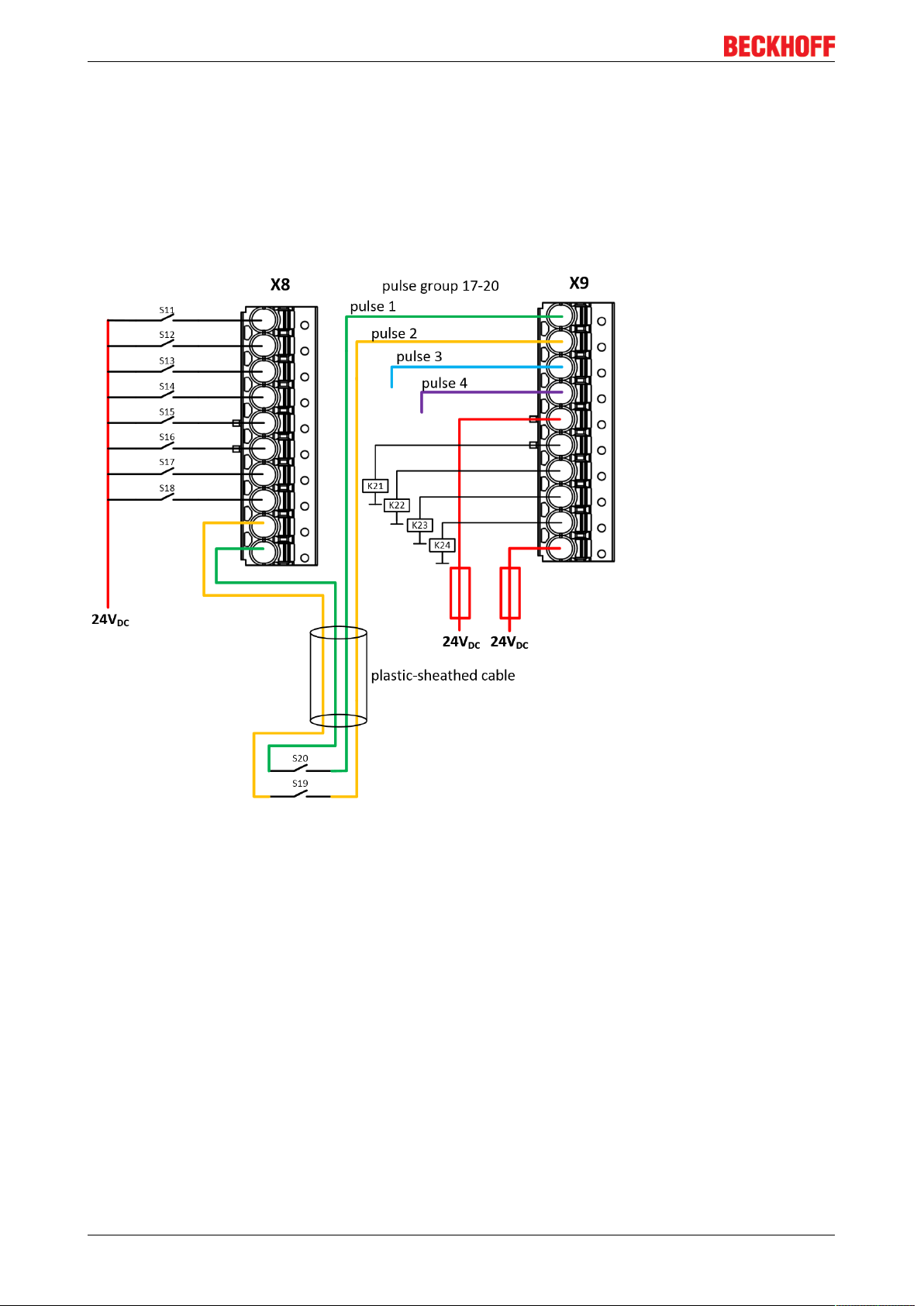
3.15.2 Clocked signals
All output groups (four outputs each) can be configured as clock outputs. The test pulses of the groups can
be set accordingly via parameters.
If a sensor such as a key switch (represented here by S19 and S20) is two-channel wired within one single
non-metallic sheathed cable, the two channels must be fed from different clock sources. This makes it
possible to detect cross-circuits or external power supplies within the common non-metallic sheathed cable
and to achieve a high level of diagnostic coverage.
Fig.16: Wiring example – clock outputs to inputs
EK196036 Version: 1.3.1
Page 37

Operation
4 Operation
4.1 Environmental conditions
Please ensure that the TwinSAFE components are only transported, stored and operated under the specified
conditions (see technical data)!
WARNING
Risk of injury!
The TwinSAFE components must not be used under the following operating conditions.
• under the influence of ionizing radiation (that exceeds the level of the natural environmental radiation)
• in corrosive environments
• in an environment that leads to unacceptable soiling of the TwinSAFE component
NOTE
Electromagnetic compatibility
The TwinSAFE components comply with the current standards on electromagnetic compatibility with regard
to spurious radiation and immunity to interference in particular.
However, in cases where devices such as mobile phones, radio equipment, transmitters or high-frequency
systems that exceed the interference emissions limits specified in the standards are operated near TwinSAFE components, the function of the TwinSAFE components may be impaired.
4.2 Installation
4.2.1 Safety instructions
Before installing and commissioning the TwinSAFE components please read the safety instructions in the
foreword of this documentation.
4.2.2 Transport / storage
Use the original packaging in which the components were delivered for transporting and storing the
TwinSAFE components.
CAUTION
Note the specified environmental conditions
Please ensure that the digital TwinSAFE components are only transported and stored under the specified
environmental conditions (see technical data).
4.2.3 Mechanical installation
4.2.3.1 De-energized condition
DANGER
Serious risk of injury!
Bring the bus system and the controller into a safe, de-energized state before installing, disassembling or
wiring of the controller!
EK1960 37Version: 1.3.1
Page 38

Operation
4.2.3.2 Control cabinet / terminal box
For operation, the TwinSAFE compact controller must be installed in a control cabinet or terminal box with
IP54 protection class according to IEC60529 as a minimum.
4.2.3.3 Installation position and minimum distances
For the prescribed installation position the mounting rail is installed horizontally and the mating surfaces of
the TwinSAFE compact controller point towards the front (see illustration below). The controller is ventilated
from below, which enables optimum cooling of the electronics through convection. The direction indication
“down” corresponds to the direction of positive acceleration due to gravity.
Fig.17: Installation position and minimum distances
In order to ensure optimum convection cooling, the distances to neighboring devices and to control cabinet
walls must not be smaller than those shown in the diagram.
4.2.3.4 Installation on mounting rails
The EK1960 is mounted on a DIN rail by inserting the device onto the DIN rail and then pressing it down
onto the rail as shown in the diagram below. In the case of flat DIN rails it may be better to position the
controller to the DIN rail from below and to snap it upwards onto the rail.
EK196038 Version: 1.3.1
Page 39

Operation
Fig.18: Mounting the EK1960 on the DIN rail
The EK1960 is released from the DIN rail by opening the two clamps on top of or underneath the device. To
do this, insert a screwdriver into the recess provided and open the clamp until it latches.
Fig.19: DIN rail clamp closed
Once the two upper or lower clamps are unlocked, the device can be taken off the DIN rail in an upward or
downward direction.
Fig.20: DIN rail clamp opened
EK1960 39Version: 1.3.1
Page 40

Operation
4.2.4 Electrical installation
4.2.4.1 Overvoltage protection
If protection against overvoltage is necessary in your system, provide an overvoltage protective circuit (surge
filter) for the power supply to the TwinSAFE compact controller.
4.2.4.2 Wiring
The connectors support the push-in wiring of individual wires and fine-wire conductors with wire-end sleeves.
In the case of multi-wire and fine-wire conductors, the latch must be depressed to connect the conductor with
the contact point.
Depress the latch with a screwdriver, insert the conductor and release the latch.
Fig.21: ZS2003-0002 Depressing the latch
EK196040 Version: 1.3.1
Page 41
4.2.4.3 Signal cables
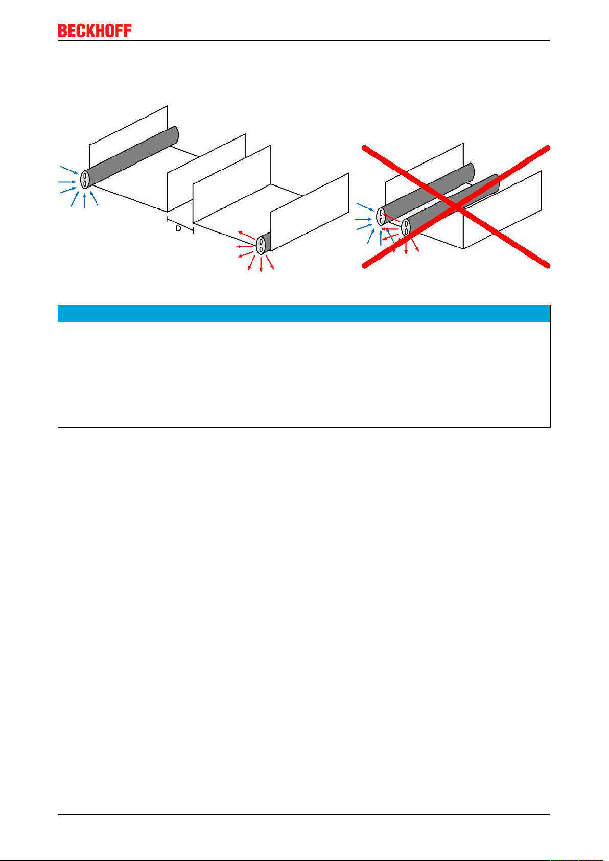
Cable routing
Fig.22: Cable routing
Operation
NOTE
Route the signal cable separately
The signal cable must be routed separately from potential sources of interference, such as motor supply cables, 230 VAC power cables etc.!
Interference caused by cables routed in parallel can influence the signal form of the test pulses and thus
cause diagnostic messages (e.g. sensor errors or OpenLoad errors).
D: Distance between the cable ducts should be as large as possible
blue arrows: signal line
red arrows: potential source of interference
The common routing of signals together with other clocked signals in a common cable also reduces the
maximum propagation, since crosstalk of the signals can occur over long cable lengths and cause diagnostic
messages.
EK1960 41Version: 1.3.1
Page 42

Operation
4.3 Configuration of the controller in TwinCAT
CAUTION
Do not change CoE objects!
Do not make modifications to the CoE objects of the TwinSAFE compact controller. Any modifications of
the CoE objects (e.g. via TwinCAT 3) will permanently set the controller to the Fail-Stop state or lead to unexpected behavior of the controller!
4.3.1 Configuration requirements
Version 3.1 build 4020 or higher of the TwinCAT automation software is required for configuring the EL6910.
The current version is available for download from the Beckhoff website (www.beckhoff.de).
TwinCAT support
The EK1960 cannot be used under TwinCAT 2
4.3.2 Insertion of a controller
An EK1960 is inserted in exactly the same way as any other Beckhoff EtherCAT device. In the list, open
Safety Terminals and select the EK1960.
Fig.23: Inserting an EK1960
EK196042 Version: 1.3.1
Page 43

Operation
Size of the process image
The process image of the EL6910 is adjusted dynamically, based on the TwinSAFE configuration
created in TwinCAT 3.
4.3.3 Creating a safety project in TwinCAT3
Further documentation
Information regarding the TwinSAFE-blocks, -groups and -connections can be found in the TwinSAFE-Logik-FB Documentation available on the Beckhoff website under
http://www.beckhoff.de/german/download/twinsafe.htm.
4.3.3.1 Add new item
In TwinCAT 3 a new project can be created via AddNewItem… in the context menu of the Safety node.
Fig.24: Creating a safety project - Add New Item
The project name and the directory can be freely selected.
Fig.25: Creating a safety project - project name and directory
EK1960 43Version: 1.3.1
Page 44

Operation
4.3.3.2 TwinCAT Safety Project Wizard
In the TwinCATSafetyProject wizard you can then select the target system, the programming language, the
author and the internal project name. Select the setting HardwareSafetyPLC as the target system and the
graphical editor as the programming language. The author and the internal project name can be freely
selected by the user.
Fig.26: TwinCAT Safety Project Wizard
4.3.3.3 Target System
After creating the project with the Project Wizard, the safety project can be assigned to the physical EK1960
TwinSAFE controller by selecting the Target System node.
Fig.27: Selecting the Target System node
The target system is set to EK1960 via the drop-down list and linked with the EK1960 controller via the link
button next to Physical Device. If online ADS access to the controller is possible, the software version,
serial number, online project CRC and rotary switch address are automatically read from the controller. The
rotary switch address must correspond to the Safe Address set by the user.
EK196044 Version: 1.3.1
Page 45

Operation
Fig.28: Linking of target system and TwinSAFE compact controller
4.3.3.4 Alias devices
The communication between the safety logic and the I/O level is realized via an alias level. At this alias level
(subnode Alias Devices) corresponding alias devices are created for all safe inputs and outputs, and also for
standard signal types. For the safe inputs and outputs, this can be done automatically via the I/O
configuration.
The connection- and device-specific parameters are set via the alias devices.
Fig.29: Starting the automatic import from the I/O configuration
If the automatic import is started from the I/O configuration, a selection dialog opens, in which the individual
terminals to be imported can be selected.
EK1960 45Version: 1.3.1
Page 46

Operation
Fig.30: Selection from the I/O tree
The alias devices are created in the safety project when the dialog is closed via OK.
Alternatively, the user can create the alias devices individually. To this end select Add and New item from
the context menu, followed by the required device.
Fig.31: Creating alias devices by the user
EK196046 Version: 1.3.1
Page 47

Operation
4.3.3.5 Parameterization of the alias device
The settings can be opened by double-clicking on the Alias Device in the safety project structure.
Fig.32: Alias Device in the safety project structure
The Linking tab contains the FSoE address, the checkbox for setting as External Device and the link to the
physical I/O device. If an ADS online connection to the physical I/O device exists, the DIP switch setting is
displayed. Re-reading of the setting can be started via the button . The links to the EL6910/EJ6910
process image are displayed under Full Name (input) and Full Name (output).
Fig.33: Links to EL6910/EJ6910 process image
The Connection tab shows the connection-specific parameters.
Fig.34: Connection-specific parameters
EK1960 47Version: 1.3.1
Page 48

Operation
Parameter Description User inter-
action required
Conn. no. Connection number - automatically assigned by the TwinCAT system No
Conn ID Connection ID: preallocated by the system, but can be changed by the user. A
Conn ID must be unique within a configuration. Duplicate connection IDs result in
an error message.
Mode FSoE master: EL6910/EJ6910 is FSoE master for this device.
FSoE slave: EL6910/EJ6910 is FSoE slave for this device.
Watchdog Watchdog time for this connection. A ComError is generated if the device fails to
return a valid telegram to the EL6910/EJ6910 within the watchdog time.
Module
Fault is
ComError
ComErrAck If ComErrAck is linked to a variable, the connection must be reset via this signal in
Info data The info data to be shown in the process image of the EL6910/EJ6910 can be
This checkbox is used to specify the behavior in the event of an error. If the
checkbox is ticked and a module error occurs on the Alias Device, this also leads
to a connection error and therefore to disabling of the TwinSAFE group, in which
this connection is defined.
the event of a communication error.
defined via these checkboxes. Further information can be found in the
documentation for TwinCAT function blocks for TwinSAFE Logic terminals.
Check
Check
Yes
Yes
Yes
Yes
The EL6910/EJ6910 support activation of a ComErrAck at each connection. If this signal is connected, the
respective connection must be reset after a communication error via the signal ComErrAck, in addition to the
ErrAck of the TwinSAFE group. This signal is linked via the link button next to COM ERR Ack. The
following dialog can be used for selecting an alias device. The signal can be cancelled via the Clear button in
the Map to dialog.
Fig.35: Selecting an alias device
The safety parameters matching the device are displayed under the Safety Parameters tab. They have to be
set correctly to match the required performance level. Further information can be found in the TwinSAFE
application manual.
EK196048 Version: 1.3.1
Page 49

Fig.36: Safety parameter for the device
4.3.3.6 Connection to AX5805/AX5806
Operation
There are separate dialogs for linking an AX5805 or AX5806 TwinSAFE Drive option card, which can be
used to set the safety functions of the AX5000 safety drive options.
Creating and opening of an alias device for an AX5805 results in five tabs; the Linking, Connection and
Safety Parameters tabs are identical to other alias devices.
Fig.37: AX5000 safety drive functions
The General AX5805 Settings tab can be used to set the motor string and the SMS and SMA functions for
one or two axes, depending on the added alias device.
EK1960 49Version: 1.3.1
Page 50

Operation
Fig.38: AX5000 safety drive options - general AX5805 settings
The Process Image tab can be used to set the different safety functions for the AX5805.
Fig.39: AX5000 safety drive options - Process Image
The parameters under the General AX5805 Settings and Process Image tabs are identical to the parameters
under the Safety Parameters tab. Offers user-friendly display and editing of the parameters. The parameters
under the Safety Parameters tab can also be edited.
The parameters for this function can be set by selecting a function in the inputs or outputs and pressing the
Edit button. New safety functions can be added in the process image by selecting an empty field (---) and
pressing Edit.
The parameter list corresponding to the safety function can be shown; in addition, an optional diagram of the
function can be shown. At present the diagram is still static and does not show the currently selected values.
EK196050 Version: 1.3.1
Page 51

Operation
Fig.40: AX5000 safety drive options - Function Diagram
4.3.3.7 External connection
An external Custom FSoE Connection can be created for a connection to a further EL69x0, EJ6910, KL6904
or third-party device. If a dedicated ESI file exists for a third-party device, the device is listed as a selectable
safety device, and the Custom FSoE Connection option is not required.
EK1960 51Version: 1.3.1
Page 52

Operation
Fig.41: Creating an external connection (Custom FSoE Connection)
Before the connection can be used and linked further, the process image size must be parameterized. This
can be set under the Process Image tab. Suitable data types for different numbers of safety data are
provided in the dropdown lists for the input and output parameters.
Fig.42: Parameterization of the process image size
Once the size is selected, the individual signals within the telegram can be renamed, so that a corresponding
plain text is displayed when these signals are used in the logic. If the signals are not renamed, the default
name is displayed in the editor (Safe Data Byte 0[0], …).
EK196052 Version: 1.3.1
Page 53

Operation
Fig.43: Renaming the individual signals within the telegram
The connection is linked under the Linking tab. The Link button next to Full Name (input) and Full
Name (output) can be used to select the corresponding variable.
Fig.44: Selecting the variables
This can be a PLC variable, for example, which is then forwarded to the remote device or can be linked
directly with the process image of an EtherCAT Terminal (e.g. EL69x0 or EL6695).
EK1960 53Version: 1.3.1
Page 54

Operation
Fig.45: Direct linking with the process image of an EtherCAT Terminal
Further information can be found in the TwinCAT documentation for the variable selection dialog.
The Connection tab is used to set the connection-specific parameters.
Fig.46: Connection-specific parameters
EK196054 Version: 1.3.1
Page 55

Operation
Detailed information about the individual settings can be found in the following table.
Parameter Description User inter-
action required
Conn. no. Connection number: is automatically assigned by the TwinCAT system No
Conn ID Connection ID: preallocated by the system, but can be changed by the user. A
Conn ID must be unique within a configuration. Duplicate connection IDs result in
an error message
Mode FSoE master: EL6910/EJ6910 is FSoE master for this device.
FSoE slave: EL6910/EJ6910 is FSoE slave for this device.
Type None: Setting for third-party equipment, for which no ESI file is available.
KL6904: Setting for KL6904 (safety parameter inactive)
EL69XX: Setting for EL6900/EL6930/EL6910/EJ6910 (safety parameter inactive)
Watchdog Watchdog time for this connection: A ComError is generated, if the device fails to
return a valid telegram to the EL6910 within the watchdog time.
Module
Fault is
ComError
Safe
Parameters
(Appl.
Param)
ComErrAck If ComErrAck is linked to a variable, the connection must be reset via this signal
Info data The info data to be shown in the process image of the EL6910/EJ6910 can be
This checkbox is used to specify the behavior in the event of an error. If the
checkbox is ticked and a module error occurs on the Alias Device, this also leads
to a connection error and therefore to disabling of the TwinSAFE group, in which
this connection is defined.
Device-specific parameters: The parameter length is automatically calculated
from the number of characters that is entered. This information will typically be
provided by the device manufacturer.
in the event of a communication error.
defined via these checkboxes. Further information can be found in the
documentation for TwinCAT function blocks for TwinSAFE Logic terminals.
Check
Check
Yes
Yes
Yes
Yes
Yes
Yes
4.3.3.8 Local safe inputs and outputs of the EK1960
An alias device must also be created for the local safe inputs and outputs of the EK1960. To do this, a new
alias device is created and the EK1960 selected via Add New item. The name of the alias device can be
freely assigned.
Fig.47: Insertion of an EK1960 alias device
After opening the alias device the Linking Mode must be set to Local. The result of this is that all settings that
are not relevant for this mode are grayed out.
EK1960 55Version: 1.3.1
Page 56

Operation
Fig.48: Switching the alias device to Local
Only the info data for inputs and outputs can be activated on the Connection tab.
Fig.49: Info data for local connection
The corresponding parameters are set for each input and output module on the Safety Parameter tab.
EK196056 Version: 1.3.1
Page 57

Operation
Fig.50: Safety parameters of the output and input modules
Overview of output parameters
PrmName Index Meaning Value
FSOUT Module 0
Settings Common
ModuloDiag
TestPulse
MultiplierDiag
TestPulse
Standard Outputs
active
Diag TestPulse
active
Diag TestPulse for
Inputs active
8000:00 Settings for output module 0 (outputs 01 - 04) -
8000:01 Test frequency of the clocking
All modules used are processed in succession in one logic cycle
respectively. With Modulo=0 the test is carried out in each cycle in
the respectively current module; with Modulo=1 only every second
pass and so on.
8000:02 Duration of the clocking 1 = 400 µs (this value will need to be
increased according to the connected load if the outputs are open
circuit or in the case of very small output currents)
8000:03 FALSE = standard outputs deactivated
TRUE = standard outputs are ANDed with the safe outputs
8000:04 FALSE: Clocking of the outputs deactivated TRUE: Clocking of the
outputs activated
8000:05 FALSE: Clocking of the outputs for local inputs deactivated
TRUE: Clocking of the outputs for local inputs activated. If TRUE is
set here the parameter DiagTestPulseActive is also set to TRUE.
0
1
FALSE
FALSE
FALSE
WARNING
Parameter Diag TestPulse for Inputs active
If this parameter is activated, all outputs of this module are switched on and can be used as test pulses for
controller inputs. In this setting the parameter DiagTestPulseActive must be set to TRUE.
Corresponding parameters exist under the indices 8000:0 to 8050:0 for the output modules 0 to 5. The
module 8060:0 exists for the relay module.
The corresponding parameters are set for each input module on the Safety Parameter tab.
EK1960 57Version: 1.3.1
Page 58

Operation
Fig.51: Safety parameters of the input modules
EK196058 Version: 1.3.1
Page 59

Overview of input parameters
PrmName Index Meaning Value
FSIN Module 9
Settings Common
InputMode 80F0:03 Only input modules 9 and 10 support the parameters
80F0:00 Settings for input module 9 (inputs 17 - 18) This setting
exists only for modules 9 and 10
Digital Mode On and Bumper Mode On. All other modules
are set to Digital Mode On and cannot be changed by the
-
- Digital Mode On
- Bumper Mode On
user.
FSIN Module 1
8071:00 Settings for input module 1 (inputs 01 - 02) -
Settings Channel
Channel1.
InputFiltertime
8071:01 Filter time for an input in the unit 100 µs. After the expiry
of this time the signal state is transmitted to the logic on
10 (1 ms)
an edge change at the input. This value must be adapted
to the length of the test pulses if they are used.
Channel1.
DiagTestPulse
FilterTime
8071:02 Filter time for an input in the unit 100 µs. This time must
elapse before a measurement of the momentary signal
state is carried out after an edge change. This value
3 (300 µs)
should be adapted to the length of the test pulses if they
are used.
Channel1.
TestPulse Diag
Mode
8071:03 The output channel from which the test pulse is expected
must be set here
External Testpulse
or drop-down list of
the EK1960
outputs
Channel2.
InputFiltertime
8071:04 Filter time for an input in the unit 100 µs. After the expiry
of this time the signal state is transmitted to the logic on
10 (1 ms)
an edge change at the input. This value must be adapted
to the length of the test pulses if they are used.
Channel2.
DiagTestPulse
FilterTime
8071:05 Filter time for an input in the unit 100 µs. This time must
elapse before a measurement of the momentary signal
state is carried out after an edge change. This value
3 (300 µs)
should be adapted to the length of the test pulses if they
are used.
Channel2.
TestPulse Diag
Mode
8071:06 The output channel from which the test pulse is expected
must be set here
External Testpulse
or drop-down list of
the EK1960
outputs
Operation
Corresponding parameters are available for input modules 1 to 10 (inputs 01 to 20) under the indices 8071:0
to 80E1:0 (in 10
steps - 8071, 8081, 8091, 80A1 and so on).
hex
The input modules 9 and 10 have additional parameters under indices 80F0:0 and 8100:0 with which the
operation modes Digital Mode On and Bumper Mode On can be set.
EK1960 59Version: 1.3.1
Page 60

Operation
Fig.52: Process data of input modules 9 and 10
The input modules 9 and 10 have a fault evaluation per channel when using the Bumper Mode, so there are
also 2 separate ModuleFault signals. When using the digital mode, both signals are set in the case of a
module fault.
Module use within the safety logic
Other than with external alias devices, only the corresponding module (two inputs or four outputs) is
assigned to the respective TwinSAFE group when selecting an input or output signal of the local
alias device. All other modules can be assigned to further TwinSAFE groups. A decoupler FB can
be used to make the inputs of a module available to a further group.
4.3.3.9 Creating the safety application
The safety application is realized in the SAL worksheet pertaining to the TwinSAFE group (SAL - Safety
Application Language).
The toolbox provides all the function blocks available on the EL6910/EJ6910.
EK196060 Version: 1.3.1
Page 61

Operation
Fig.53: Function blocks available for EL6910/EJ6910
The function blocks can be moved from the toolbox into the SAL worksheet via drag and drop. Variables can
be created by clicking next to a function block input or output, which can then be linked with alias devices in
the Variable Mapping dialog.
Fig.54: Function block on the SAL worksheet
EK1960 61Version: 1.3.1
Page 62

Operation
Once the pointer connector has been selected from the toolbox, connections between the
input and output ports of the function blocks can be dragged with the mouse.
Fig.55: Dragging a connection between two function blocks
EK196062 Version: 1.3.1
Page 63

Operation
Fig.56: Connection between two function blocks
4.3.3.10 Networks
For structuring the safety application, several networks can be created within a sal worksheet. Right-click in
the worksheet and select Add After and Network or Add Before and Network to create a network after or
before the current network.
Fig.57: Creating a network
The instance path to the FB port to be linked can be specified, in order to exchange signals between the
networks. The instance path consists of the network name, the FB name and the FB port, each separated by
a dot. The input of the instance path is case-sensitive.
<Network name>.<FB name>.<FB port name>
Sample: Network1.FBEstop1.EStopIn3
EK1960 63Version: 1.3.1
Page 64

Operation
Alternatively, Change Link can be selected by opening the context menus next to the FB port.
Fig.58: Change Link
This function opens a dialog for selecting a suitable FB port.
Fig.59: Dialog for selecting a suitable FB port
Once the link has been created on one side of the connection, the link is automatically set/displayed on the
opposite side.
Fig.60: Link display
EK196064 Version: 1.3.1
Page 65

Operation
4.3.3.11 TwinSAFE groups
It makes sense to create TwinSAFE groups in cases where different machine safety zones are to realize, or
simply in order to separate the fault behavior. Within a group, a FB or connection error (here: alias device)
leads to a group error and therefore to switching off all outputs for this group. If an error output of an FB is
set, it will be forwarded as a logical 1 signal.
A group can be created by opening the context menu of the safety project and selecting Add and New
Item....
Fig.61: Creating a TwinSAFE group
Like the first group, the group of a subitem for the alias devices and a sal worksheet.
Fig.62: Components of the TwinSAFE group
The instance path to the FB port to be linked can be specified, in order to exchange signals between the
groups. The instance path consists of the group name, the FB name and the FB port, each separated by a
dot. The input of the instance path is case-sensitive.
<group name>.<network name>.<FB name>.<FB port name>
Sample: TwinSafeGroup1.Network1.FBEstop1.EStopIn3
Alternatively, Change Link can be selected by opening the context menus next to the FB port.
EK1960 65Version: 1.3.1
Page 66

Operation
Fig.63: Change Link
This function opens a dialog for selecting a suitable FB port.
Fig.64: Dialog for selecting a suitable FB port
Once the link has been created on one side of the connection, the link is automatically set/displayed on the
opposite side.
EK196066 Version: 1.3.1
Page 67

Operation
Fig.65: Link display
4.3.3.12 Variables of the TwinSAFE group
The inputs and outputs of the TwinSAFE groups are consolidated under the Group Ports tab of the Variable
Mapping dialog.
Group inputs EL6910/EJ6910
For a project to be valid, as a minimum the signals Run/Stop and ErrAck must be linked.
Fig.66: The Variable Mapping dialog
EK1960 67Version: 1.3.1
Page 68

Operation
Group Port Direction Description
Err Ack IN Error Acknowledge for resetting errors within the group
- Signal must be linked with a standard variable
Run/Stop IN 1 - Run; 0 – Stop
- Signal must be linked with a standard variable
Module
Fault
Com Err OUT Communication error in one of the connections
FB Err OUT Error at one of the FBs used
Out Err OUT not used
Other Err OUT ModuleFault OR AnalogValueFault OR WaitComTimeoutFault
Com Startup OUT At least one of the connections of this group is in startup
FB Deactive OUT
FB Run OUT FBs of the TwinSAFE group are processed
In Run OUT TwinSAFE group is in RUN state
Group State
IN Input for an error output of another module that is connected, e.g.
EK1960
The group was deactivated. (See also chapter Customizing / disabling
TwinSAFE groups [}97])
Value Status Description
1 RUN Input RUN=1, no error in the group, and all connections have started up
without error
2 STOP Input RUN = 0
4 ERROR Group is in error, see Diagnostic information
5 RESET After an error has occurred, all errors have been rectified and the ErrAck
signal is 1
6 START The group remains in this state as long as not all connections have
started up after the start of the group (RUN=1)
7 STOPERROR When the group is started or initialized, it assumes the STOPERROR
status if the TwinSAFE connections are assigned to the group.
The group switches from STOPERROR state into ERROR state if the
Run input is TRUE.
16 DEACTIVE Group was deactivated via customizing
17 WAITCOMERROR This state is set when the customizing function “Passivate” is selected
and the system waits for ComError of the group
Group Diag
Value Status Description
0 - No error
1 FBERROR at least one FB is in ERROR state
2 COMERROR at least one connection is faulty
3 MODULEERROR the input ModuleFault is 1
4 CMPERROR On startup, at least one analog FB input deviates from the last saved
value (Power-On Analog Value Check Error)
5 DEACTIVATE
ERROR
6 RESTARTERROR The TwinSAFE Logic program was restarted because the EtherCAT
In "passivate manual control unit" mode the timeout has elapsed while
waiting for the COM error
connection was restarted or a user logged in without reloading the
TwinSAFE Logic program (or parts of it).
EK196068 Version: 1.3.1
Page 69

Operation
4.3.3.13 Order of the TwinSAFE groups
The order of the groups can be changed, in order to realize a defined processing sequence of the safety
application.
To this end, select the entry Edit TwinSAFE Group Order via the node menu of the safety project node. A
dialog opens, in which the order of the groups can be changed. The individual groups do not necessarily
have to be numbered in consecutive ascending order. The numbering can contain gaps.
Fig.67: Context menu Edit TwinSAFE Group Order
The current group order is shown in the column Current Value. The new order is specified by entering a
value in the column New Value, followed by OK.
Fig.68: Dialog Change Execution Order of TwinSAFE Groups
4.3.3.14 Command line
The command line below the SAL worksheet can be used to enter commands for executing functions.
EK1960 69Version: 1.3.1
Page 70

Operation
Fig.69: The command line below the SAL worksheet
Currently the commands listed in the following table are supported.
Command Description
FBNAME FB_INSTANCENAME NETWORKNAME; Adding a function block
Sample: safeAnd FBAnd1 Network1
FB_INSTANCENAME->PORTNAME =
VARIABLE_NAME;
FB_INSTANCENAME->PORTNAME =
FB_INSTANCENAME->PORTNAME;
Creating a variable mapping
Sample: FBAnd1->AndIn1 = testVariable
Creating a connection between two FBs
Sample: FBAnd1->AndIn1 = FBOr1->OrOut;
4.3.3.15 FB port properties
The behavior of the inputs can be parameterized by opening the properties for the upper input of an input
pair or an individual input of the function block. For an input group, such as the function block ESTOP, the
individual inputs to be activated or deactivated, and single- or two-channel evaluation can be set.
Fig.70: FB port properties
EK196070 Version: 1.3.1
Page 71

Operation
Channel Interface Description
Both Deactivated Both inputs are deactivated
Single-Channel 1 Activated Channel 1: Single-channel evaluation
Channel 2: deactivated
Single-Channel 2 Activated Channel 1: deactivated
Channel 2: Single-channel evaluation
Single-Channel Both Activated Channel 1: Single-channel evaluation
Channel 2: Single-channel evaluation
Two-Channel Both inputs are activated, and two-channel evaluation with
Discrepancy Time (ms)
If the Two-Channel evaluation is enabled, the corresponding Discrepancy time (ms) can be set in
milliseconds. For each input there is a setting to indicate whether the input should be evaluated as Break
Contact (NC) or Make Contact (NO). When a variable or a connecting line is connected to the function block,
the corresponding channel is enabled automatically.
Fig.71: Make Contact (NO) / Break Contact (NC) setting
These settings are also accessible for each individual port of an FB via the context menu item Change InPort
Settings.
EK1960 71Version: 1.3.1
Page 72
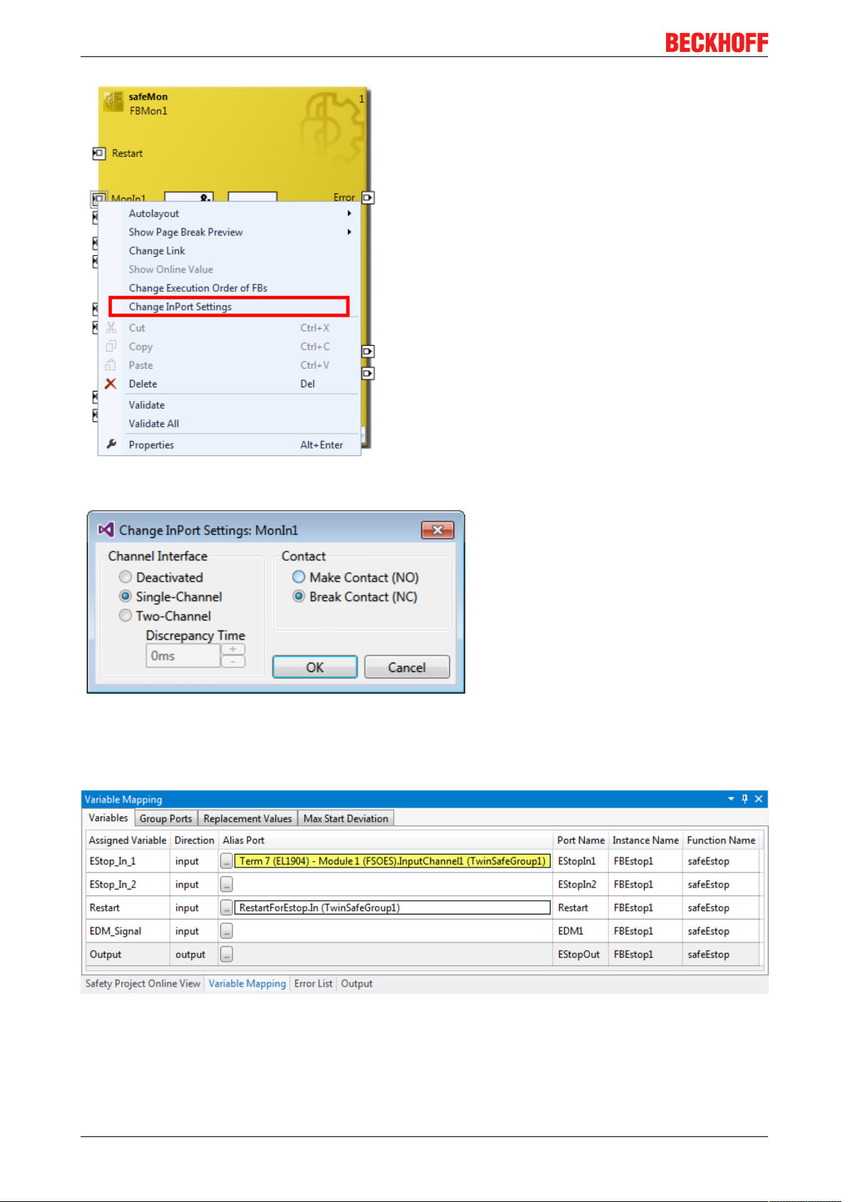
Operation
Fig.72: Menu Change Inport Settings
Fig.73: Dialog Change InPort Settings
4.3.3.16 Variable Mapping
Fig.74: Variable Mapping
EK196072 Version: 1.3.1
Page 73

Operation
Variables are linked to the alias devices in the Variable Mapping window. Use the Link button to open
the selection dialog for the alias port. Safe only signal types or safe and standard signal types are offered in
the selection dialog, depending on the port setting of the FB. Safe Boolean signals are shown with a yellow
background, standard signal types with a white background.
If several outputs are to be written by one variable, these signals can be assigned by holding down the CTRL
key and selecting the channels.
Fig.75: Selection dialog for the alias port
4.3.3.17 Safety toolbars
Once the development of the safety project is complete, the project has to be loaded onto the target system,
in this case EL6910/EJ6910. To this end the toolbars TwinCAT Safety and TwinCAT Safety CRC have to be
added.
Fig.76: Activation of the TwinCAT Safety and TwinCAT Safety CRC toolbars
Fig.77: Display of the TwinCAT Safety and TwinCAT Safety CRC toolbars
EK1960 73Version: 1.3.1
Page 74

Operation
Toolbar TwinCAT Safety
Icon Name Description
Verify Safety Project The safety project is checked for validity.
Verify Complete Safety
Project
Download Safety Project Loading the safety project onto the target system, here EL6910/
Delete Safety Project Deleting the safety project from the target system, here EL6910/
Show Online Data of Safety
Project
Customize Safety Project Customizing the safety project (switching off TwinSAFE groups and
Toolbar TwinCAT Safety CRC
Icon Name Description
CRC Toolbar Left-click on the toolbar to initiate an update of the CRCs by the user.
CRC Toolbar Green icon: All CRCs are identical
Online CRC CRC of the safety project on EL6910/EJ6910. This value is read online
The safety project including the hardware level is checked for validity.
EJ6910
EJ6910
Switching on the Online View for the safety project.
setting of safe substitute values for the group outputs). This is possible
if the online and offline CRC are the same and at least one group has
been configured for customizing.
Red icon: CRCs are different
by the EL6910/EJ6910. In the absence of an ADS connection to the
EL6910/EJ6910, this value is displayed with .
Downloaded
CRC
Offline CRC CRC of the current safety project, as stored in the safety editor. A CRC
CRC of the safety project that was loaded last. If no safety project is
loaded when the TwinCAT project is opened, the value is displayed
with .
is displayed, if the stored project is valid. If the project is invalid,
is displayed as CRC.
4.3.3.18 Checking the TwinSAFE addresses
The hardware addresses of the alias devices used can be checked and set via the dialog Check Safe
Addresses.
To this end, select the entry Check Safe Addresses via the node menu of the safety project node. A dialog
opens, which lists all alias devices that use hardware addresses. The addresses set in the software (Safe/
FSoE Address) and the hardware addresses (Hardware Address) are shown in separate columns for each
alias device and for the target system. In the column Take Hardware Address the user can specify whether
the hardware addresses for the alias devices settings are applied when the dialog is closed via the OK
button.
EK196074 Version: 1.3.1
Page 75

Fig.78: Check Safe Addresses context menu
Operation
Fig.79: Check Safe Addresses dialog
4.3.4 Downloading the safety application
Before downloading the safety project to the EL6910/EJ6910 or a logic component, the project should first
be checked for validity. If the hardware is complete, the hardware level can be used for checking, or
checking can take place at the project level , if online access is only available for the EL6910/EJ6910 or
the logic component. If the check returns no errors, the project download can continue.
CAUTION
Use only qualified tools
Only use a qualified tool (see note on system limits) for loading, verifying and enabling the project on the
EL6910/EJ6910 or the logic component!
User name and password are case-sensitive
Pay attention to upper/lower case characters for the user name and password.
The standard user is Administrator, the standard password is TwinSAFE.
EK1960 75Version: 1.3.1
Page 76

Operation
NOTE
Power supply during download
Make sure that the TwinSAFE Logic is not switched off during the download. This can lead to unexpected
behavior or permanently disable the TwinSAFE Logic.
WARNING
Execution of the safety application
During a login or download of a safety application, the execution of the current project is stopped on the
TwinSAFE Logic.
Fig.80: Download Project Data – The Login dialog
In the Download Project Data dialog specify the user name, the serial number of the EL6910/EJ6910 or the
logic component onto which the project is to be loaded, and the user password. The default user name is
Administrator, the default-password is TwinSAFE. Use the Next button to move to the next dialog.
Fig.81: Download Project Data – The Select Project Data dialog
In the Select Project Data dialog select Complete Project Data to load the whole project onto the EL6910/
EJ6910 or the logic component. Use the Next button to move to the next dialog.
EK196076 Version: 1.3.1
Page 77

Fig.82: Download Project Data – The Download Result dialog
Operation
Once the download is complete, the download results are displayed. Use the Next button to move to the next
dialog.
Fig.83: Download Project Data – The Final Verification dialog
The locally calculated CRCs and the online CRCs of the safety project are displayed in the Final Verification
dialog. They are automatically checked for equality and displayed via the column Verification Result. The
user must also check these data for equality and then confirm this by ticking the checkbox. Use the Next
button to move to the next dialog.
EK1960 77Version: 1.3.1
Page 78

Operation
Fig.84: Download Project Data – The Activation dialog
In the Activation dialog the user re-enters the password to activate the safety project on the EL6910/EJ6910
or the logic component. Use the Finish button to complete the download of the safety project.
WARNING
Verification of the input and output process data
After downloading the safety-related program to the TwinSAFE logic, the user must check that the input
and output process data of the TwinSAFE logic are plausible, within the valid value range and in the expected magnitude. This is especially true for analog signals, which are transmitted via e.g. PROFIsafe,
FSoE sensors, TwinSAFE SC terminals or external control systems to the TwinSAFE logic. It is particularly
important to check whether the device uses the Motorola or the Intel format or Big or Little Endian.
Project data Description
Safe Logic Data Safe Logic Data contains the safety related program.
Mapping Data Mapping Data contains the link data for inputs, outputs, function blocks, connections
etc.
Parameter Data Parameter Data contains the safe user parameters that are stored on the TwinSAFE
Logic. These can be safe substitute values and the user parameters of the connections.
Info Data Info Data contains the settings which Info Data for connections, function blocks, groups
etc. are activated and have to be filled by the TwinSAFE Logic.
Info Data of the safety project
The Info Data will NOT take effect to the calculation of the project CRC. This allows the Info Data to
be changed at a later stage without changing the project CRC.
If the Info Data for an existing project are changed, a project download including at least the Info
Data must be carried out, despite the fact that the CRC is unchanged, otherwise the Info Data will
not be filled. In addition, the TwinCAT configuration must be activated so that the process image
size in TwinCAT matches the expected size within the TwinSAFE Logic.
EK196078 Version: 1.3.1
Page 79

4.4 Info data
4.4.1 Info data for the connection
Info data for connections can be enabled on the Connection tab of the alias device.
Fig.85: Enabling the info data for connections
Operation
The info data are shown in the I/O tree structure below the EL6910 in the process image. From here, these
signals can be linked with PLC variables. Further information on the included data can be found in the
documentation for TwinCAT function blocks for TwinSAFE logic terminals. Use the checkbox Show Input/
Output Data as byte array under Target System to adjust the process image.
Fig.86: Checkbox for the connection info data
Fig.87: Info data for the connection in the I/O tree structure as byte array
EK1960 79Version: 1.3.1
Page 80

Operation
Fig.88: Info data for the connection in the I/O tree structure as individual data
4.4.2 Info data for function blocks
For function blocks, info data can be enabled in the properties of the function block.
Fig.89: Enabling the info data for function blocks
The info data are shown in the I/O tree structure below the EL6910 in the process image. From here, these
signals can be linked with PLC variables. Further information on the included data can be found in the
documentation for TwinCAT function blocks for TwinSAFE logic terminals.
EK196080 Version: 1.3.1
Page 81

Operation
Fig.90: Info data for the function block in the I/O tree structure
4.4.3 Info data for the TwinSAFE group
For TwinSAFE groups, info data can be enabled via the properties of the TwinSAFE group.
Fig.91: Enabling the info data in the properties of the TwinSAFE group
The info data are shown in the I/O tree structure below the I/O device in the process image. From here,
these signals can be linked with PLC variables. Further information on the included data can be found in the
documentation for TwinCAT function blocks for TwinSAFE logic terminals.
EK1960 81Version: 1.3.1
Page 82

Operation
Fig.92: Info data for the TwinSAFE group in the tree structure
4.4.4 Info data for the device
The info data for the EK1960 can be activated on theTarget System tab. These are the serial number of the
EK 1960 and the current online-CRC of the safety project.
Fig.93: Activation of the info data for the EK1960
The info data are shown in the I/O tree structure below the EK1960 in the process image. From here, these
signals can be linked with PLC variables.
EK196082 Version: 1.3.1
Page 83

Operation
Fig.94: Info data in the EK1960 tree structure
Info data of the internal EK1960 inputs and outputs
In addition to the project CRC and the serial number, the local inputs and outputs of the EK1960 connection
are shown under Device Info Data. The inputs, outputs, module errors and module ErrAck signals are shown
below the entry Internal I/O.
Fig.95: Activating the info data for the local EK1960 connection
4.5 Version history
The version history button under Target System can be used to read the version history of the EL6910,
EJ6910 or EK1960. It includes the user, the date, the version and the CRC of the safety projects loaded on
the EL6910, EJ6910 or EK1960.
Fig.96: Version History
EK1960 83Version: 1.3.1
Page 84

Operation
4.6 User Administration
User administration is called up via the Target System tree item. Use Get User List to read the current list of
users of the EL6910, EJ6910 or EK1960. The user Administrator cannot be deleted. The default password
can and should be replaced with a customer-specific password. This is done via the Change Password
button. The default password is TwinSAFE. The password must be at least 6 characters long. A maximum of
40 users can be created.
Fig.97: User Administration
The administrator password is required to create or delete users. Open the Login dialog by left-clicking on
Add User(s).
Fig.98: User Administration - Login
The Add User dialog opens once the correct serial number and administrator password have been entered.
EK196084 Version: 1.3.1
Page 85

Fig.99: User Administration - Add New User(s) - User Credentials
Operation
Fig.100: User Administration - Add New User(s) - Access Rights
Enter the new user and the corresponding password (twice). The password must be at least 6 characters
long. In addition, select the rights for the new user. Use the button to apply these data and
display them in the New User list.
EK1960 85Version: 1.3.1
Page 86

Operation
Fig.101: User Administration - New User added
Several users can be created before leaving the dialog via the Finish button.
Access Rights Description
Change Password Users can change their password.
Download Safe Logic Data The user can load the safety-related program onto the EL6910, EJ6910 or
EK1960.
Download Mapping Data The user can load the mapping data for inputs, outputs, FBs etc. onto the
EL6910, EJ6910 or EK1960.
Download Safe User Data/
Replacement Values
Download Info Data The user can activate and load the info data for connections and FBs on
Download Project Data in
Restore Mode
Activate / Deactivate Groups The user can execute Customizing (enable and disable TwinSAFE groups)
The user can change safe user parameters on the EL6910, EJ6910 or
EK1960 and also change and load safe substitute values
the EL6910, EJ6910 or EK1960.
The user can perform a restore. Not currently supported.
on the EL6910, EJ6910 or EK1960.
4.7 Backup/Restore
Following the exchange of an EL6910, EJ6910 or EK1960, the previous project can be loaded to the new
device using the Backup/Restore mechanism.
In order to be able to use this functionality, the Backup/Restore mechanism must be enabled in the safety
project, and the terminals must be selected, on which the current CRC of the safety project is to be stored.
For a restore operation the user can specify the minimum number of selected terminals on which the correct
CRC must be stored.
Using the checkbox Restore User Administration the user can specify whether the user administration should
be transferred to the new device via the restore mechanism.
EK196086 Version: 1.3.1
Page 87

Operation
Fig.102: Backup/Restore
In order to be able to use the Backup/Restore mechanism, create a backup of the current safety project and
store it on the hard disk of the controller, for sample. To carry out a restore, the user can either check when
starting the controller whether the serial number of the EL6910, EJ6910 or EK1960 has changed, or start the
restore manually via a service menu, e.g. in the visualization. Detailed information about the Backup/Restore
mechanism is available from Beckhoff Support.
Restore
If a project that doesn't match the system is loaded during a restore, this will only be detected when
the distributed CRCs are checked. The previous project is then deleted from the logic terminal. This
cannot be undone.
One possible sequence for checking whether a restore is carried out is shown in the following sequence
chart.
EK1960 87Version: 1.3.1
Page 88

Operation
Fig.103: Restore check sequence chart
Function blocks for backup/restore
The PLC function blocks with which a backup and restore to a TwinSAFE logic component (currently
EL6910, EJ6910 or EK1960) can be carried out are available through Beckhoff Support. This is a compiled
library that can be installed in the TwinCAT Library Repository.
The TC3_EL6910_Backup_Restore library contains two PLC function blocks. FB_SAVELOGICPROGRAM
and FB_RESTORELOGICPROGRAM.
FB_SAVELOGICPROGRAM
EK196088 Version: 1.3.1
Page 89

Fig.104: FB_SAVELOGICPROGRAM illustration
Fig.105: FB_SAVELOGICPROGRAM parameters
Operation
FB_RESTORELOGICPROGRAM
Fig.106: FB_RESTORELOGICPROGRAM illustration
Fig.107: FB_RESTORELOGICPROGRAM parameters
Sample
PROGRAM MAIN
VAR
fb_save:FB_SAVELOGICPROGRAM;
fb_restore:FB_RESTORELOGICPROGRAM;
StartBackup:BOOL;
EL6910AmsNetID AT %I*:ARRAY [0..5] OF BYTE;
EL6910port AT %I*:WORD;
internalBuffer: array[0..16#FFFF] of byte;
FileString: T_MaxString := 'c:\temp\safety\complibTest_EL6910.bin';
LocalAmsNetID: T_AmsNetID := '172.55.76.53.1.1';
SaveDone: BOOL;
SaveResult: STRING(200);
SaveErr: BOOL;
StartRestore: BOOL;
internalbuffer2: array[0..16#FFFF] of Byte;
RestoreDone: BOOL;
EK1960 89Version: 1.3.1
Page 90
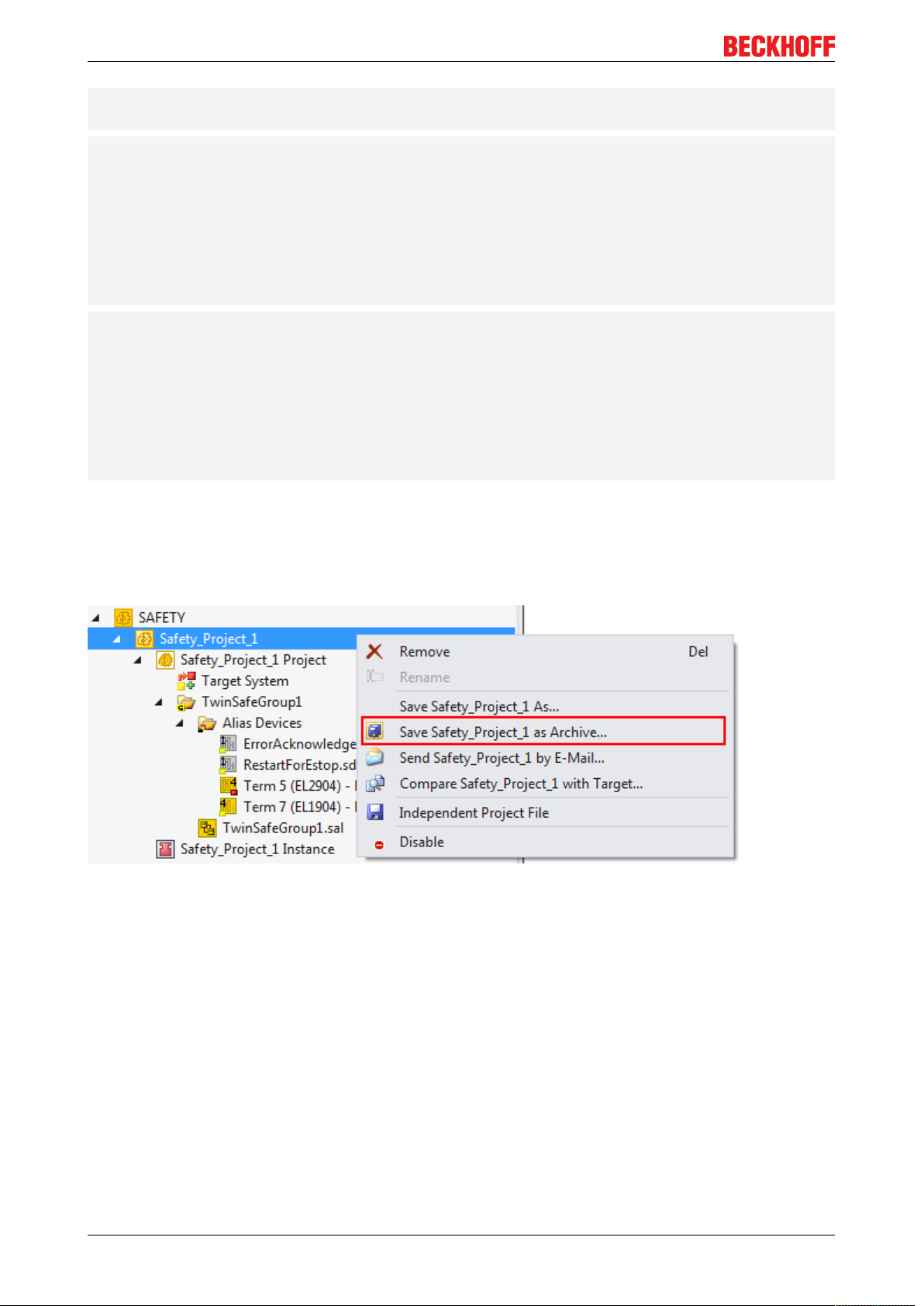
Operation
RestoreResult: STRING(200);
RestoreErr: BOOL;
END_VAR
// Backup of the TwinSAFE logic program
fb_save(
bExecute:=StartBackup,
au8EcatNetId:=EL6910AmsNetID,
u16EcatPort:=EL6910port,
u32BufferAddress:=ADR(internalBuffer),
u32BufferSize:=SIZEOF(internalBuffer),
sFileName:=FileString,
sNetIDWriteFile:=LocalAmsNetID,
Done=>SaveDone,
sResult=>SaveResult,
bErr=>SaveErr);
// Restore of the TwinSAFE logic program
fb_restore(
bExecute:=StartRestore,
au8EcatNetId:=EL6910AmsNetID,
u16EcatPort:=EL6910port,
u32BufferAddress:=ADR(internalbuffer2),
u32BufferSize:=SIZEOF(internalBuffer2),
sFileName:=FileString,
sNetIDReadFile:=LocalAmsNetID,
Done=>RestoreDone,
sResult=>RestoreResult,
bErr=>RestoreErr);
4.8 Export/import of the safety project
The safety project can be archived via the context menu of the safety project. The data type of this archive is
*.tfzip.
Fig.108: Archiving the safety project
The safety project can be exported to XML format one level below the safety project node. This XML format
can be used for exchange between TwinCAT3 and TwinCAT2.
The menu item Export project (as bin file) can be used to save the safety project in a binary format, so that it
can be used by the TwinSAFE loader, for sample.
EK196090 Version: 1.3.1
Page 91

Operation
Fig.109: Saving the safety project in a binary format (e.g. for the TwinSAFE loader)
A previously exported safety project can be imported via the context menu of the main Safety entry in the
TwinCAT project structure. Add Existing Item… can be used to select the file type for the import.
Fig.110: Selecting the file type for importing a safety project
The following file types are supported:
• Safety project files *.splc,
• Safety project archives *.tfzip
• Safety projects in XML format
EK1960 91Version: 1.3.1
Page 92

Operation
Fig.111: Importing a safety project
4.9 Diag History tab
Any errors that occur in the EL6910, EJ6910 or EK1960 are stored in the their diag history. The diag history
can be viewed by selecting the EL6910, EJ6910 or EK1960 in the I/O tree structure and then selecting the
Diag History tab. Use the Update History button to fetch the current from the EL6910, EJ6910 or EK1960.
Error within the logic; the function blocks and the connections are stored with a corresponding timestamp.
Fig.112: Diag History
Use the Advanced… button to open the advanced settings. Here, the user can customize the behavior of the
diag history.
EK196092 Version: 1.3.1
Page 93

Operation
Fig.113: Diag History - Advanced Settings
Advanced Settings
Setting Description
Message Types • disable Info
Messages with status Info are not stored in the diag history
• disable Warnings
Messages with status Warning are not stored in the diag history
• disable Errors
Messages with status Error are not stored in the diag history
Emergency In addition to saving the message in the diag history, an emergency
object is sent, which is displayed in the logger window of TwinCAT.
Overwrite / Acknowledge Mode This setting is currently not supported.
4.10 TwinSAFE SC configuration
The TwinSAFE SC technology enables communication with standard EtherCAT terminals via the Safety over
EtherCAT protocol. These connections use another checksum, in order to be able to distinguish between
TwinSAFESC and TwinSAFE. Eight fixed CRCs can be selected, or a free CRC can be entered by the user.
By default the TwinSAFE SC communication channel of the respective TwinSAFE SC component is not
enabled. In order to be able to use the data transfer, the corresponding TwinSAFE SC module must first be
added under the Slots tab. Only then is it possible to link to a corresponding alias device.
EK1960 93Version: 1.3.1
Page 94

Operation
Fig.114: Adding the TwinSAFE SC process data under the component, e.g. EL5021-0090
Additional process data with the ID TSC Inputs, TSC Outputs are generated (TSCTwinSAFESingleChannel).
Fig.115: TwinSAFE SC component process data, example EL5021-0090
A TwinSAFE SC connection is added by adding an alias devices in the safety project and selecting TSC
(TwinSAFE Single Channel)
Fig.116: Adding a TwinSAFE SC connection
After opening the alias device by double-clicking, select the Link button next to Physical Device, in
order to create the link to a TwinSAFE SC terminal. Only suitable TwinSAFE SC terminals are offered in the
selection dialog.
EK196094 Version: 1.3.1
Page 95

Operation
Fig.117: Creating a link to TwinSAFE SC terminal
The CRC to be used can be selected or a free CRC can be entered under the Connection tab of the alias
device.
Entry Mode Used CRCs
TwinSAFE SC CRC 1 master 0x17B0F
TwinSAFE SC CRC 2 master 0x1571F
TwinSAFE SC CRC 3 master 0x11F95
TwinSAFE SC CRC 4 master 0x153F1
TwinSAFE SC CRC 5 master 0x1F1D5
TwinSAFE SC CRC 6 master 0x1663B
TwinSAFE SC CRC 7 master 0x1B8CD
TwinSAFE SC CRC 8 master 0x1E1BD
Fig.118: Selecting a free CRC
These settings must match the settings in the CoE objects of the TwinSAFE SC component.
The TwinSAFE SC component initially makes all available process data available. The Safety Parameters
tab typically contains no parameters. The process data size and the process data themselves can be
selected under the Process Image tab.
EK1960 95Version: 1.3.1
Page 96
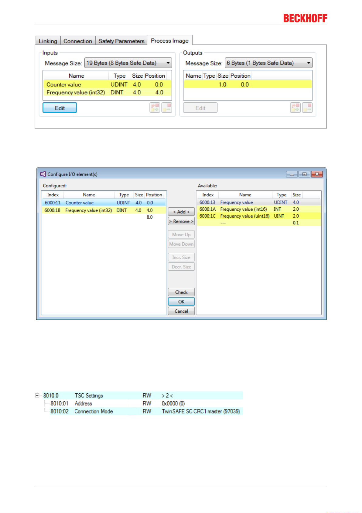
Operation
Fig.119: Selecting the process data size and the process data
The process data (defined in the ESI file) can be adjusted to user requirements by selecting the Edit button
in the dialog Configure I/O element(s).
Fig.120: Selection of the process data
The safety address together with the CRC must be entered on the TwinSAFE SC slave side. This is done via
the CoE objects under TSC settings of the corresponding TwinSAFE SC component (here, for example,
EL5021-0090, 0x8010: 01 and 0x8010: 02). The address set here must also be set in the alias device as
FSoE address under the Linking tab.
Under the object 0x80n0:02 Connection Mode the CRC to be used is selected or a free CRC is entered. A
total of 8 CRCs are available. A free CRC must start with 0x00ff in the high word.
Fig.121: CoE objects 0x8010:01 and 0x8010:02
EK196096 Version: 1.3.1
Page 97
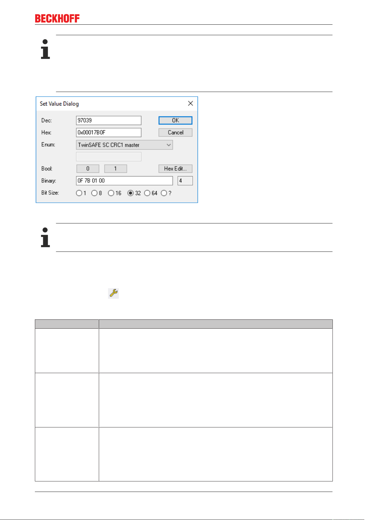
Operation
Object „TSC Settings”
Depending on the terminal, the index designation of the configuration object „TSC Settings“ can
vary.
Example:
- EL3214-0090 and EL3314-0090, „TSC Settings“, Index 8040
- EL5021-0090, „TSC Settings“, Index 8010
- EL6224-0090, „TSC Settings“, Index 800F
Fig.122: Entering the safety address and the CRC
TwinSAFE SC connections
If several TwinSAFESC connections are used within a configuration, a different CRC must be selected for each TwinSAFESC connection.
4.11 Customizing / disabling TwinSAFE groups
The function Customizing can be selected in the safety toolbars or via the TwinSAFE menu. It can be
used to enable and disable groups. There are different deactivation methods, as shown in the following
table.
Deactivation Description
Permanent
deactivation
Deactivation until the
EL6910 is switched off
and back on again
Deactivation of
manual control unit
The TwinSAFE group is permanently disabled by the user. The substitute values
parameterized for the group are set for the group outputs.
If this group is enabled again, the RUN signal for this group must change from 0 to 1,
in order for the group to start.
Parameter:
Permanent Deactivation Allowed: TRUE/FALSE
The TwinSAFE group is disabled until the EL6910 is switched on again. The
substitute values parameterized for the group are set for the group outputs. This
setting cannot be used as default setting for the safety program download.
If this group is enabled again (other than by switching off and on again), the RUN
signal for this group must change from 0 to 1, in order for the group to start.
Parameter:
Temporary Deactivation Allowed: TRUE/FALSE
After starting the deactivation, the connection defined in the group must report a
COM error after a period of 10 seconds, for sample (default setting). If this is not the
case, a group error set and corresponding diagnostic message is generated. Only
one connection may be defined in the group, which must be a master connection.
Parameter:
Passification Allowed : TRUE/FALSE
Timeout Passification Allowed: Time in ms
EK1960 97Version: 1.3.1
Page 98

Operation
The customization can also be carried out during the download of the safety application.
In order to be able to perform a customization, the groups must be set accordingly. This is done via the
group properties.
Fig.123: Properties of the TwinSAFE group
If one of the Customizing parameters (Passification Allowed, Permanent Deactivation Allowed or Temporary
Deactivation Allowed) is set to TRUE, all outputs of the TwinSAFE group that are not Safety Alias Devices
are listed in the list of Replacement Values. Here you can parameterize the substitute values to be written to
the output in the event of deactivation of the group.
Fig.124: Replacement values for the TwinSAFE group
When the Customizing function is selected, the login dialog opens for the user to enter their login data.
This login must give permission for customizing.
EK196098 Version: 1.3.1
Page 99

Fig.125: Login
The Customizing dialog opens once the user has entered the data and selected Next.
Operation
The current group status is indicated with a green background.
Fig.126: Customizing TwinSAFE Groups
The user can select the new status via the option area. In the sample below Deactivate Temporarily is
selected. Use the Finish button to close the dialog and execute the required option.
Fig.127: Customized TwinSAFE Group
EK1960 99Version: 1.3.1
Page 100

Operation
TwinSAFE Logic in PreOP state
If Customizing is carried out on a TwinSAFE Logic with EtherCAT status PreOP, the customizing of
a group does not become active. Customizing must be carried out again if the TwinSAFE Logic is in
the EtherCAT status SafeOP or OP.
4.12 Saving the analog group inputs persistently
EL6910, EJ6910 and EK1960 support persistent saving of analog input values in an internal memory. When
the group starts up, the stored data are compared with the current data. Under the tab Max Start Deviation, a
corresponding deviation can be specified for each defined analog input value of the group.
Fig.128: Specifying deviations for analog input values
In the group properties the general settings for setting substitute values and checking the analog values on
group startup can be parameterized. Setting the parameter Verify Analog FB Inputs at Group Startup to
TRUE activates saving of all analog group inputs.
Fig.129: Activate saving of all analog group inputs
EK1960100 Version: 1.3.1
 Loading...