

Page 1
Documentation
EK110x, EK15xx
EtherCAT Bus Coupler
3.6
2017-10-05
Version:
Date:
Page 2

Page 3

Table of contents
EK110x, EK15xx 3Version: 3.6
Table of contents
1 Foreword ....................................................................................................................................................5
1.1 Overview EtherCAT Coupler .......................................................................................................... 5
1.2 Notes on the documentation........................................................................................................... 6
1.3 Safety instructions .......................................................................................................................... 7
1.4 Documentation issue status............................................................................................................ 8
1.5 Version identification of EtherCAT devices..................................................................................... 8
2 Product overview.....................................................................................................................................13
2.1 Overview of EtherCAT couplers ................................................................................................... 13
2.2 Coupler with RJ45 connection ...................................................................................................... 15
2.2.1 EK1100 ............................................................................................................................15
2.2.2 EK1101, EK1101-xxxx .....................................................................................................17
2.3 Coupler with M8 connection ......................................................................................................... 22
2.3.1 EK1100-0008 ...................................................................................................................22
2.4 Coupler with optical fiber connection ............................................................................................ 25
2.4.1 EK1501 ............................................................................................................................25
2.4.2 EK1501-0010 ...................................................................................................................27
2.5 Coupler with POF connection ....................................................................................................... 29
2.5.1 EK1541 ............................................................................................................................29
3 Basics .......................................................................................................................................................31
3.1 EtherCAT basics........................................................................................................................... 31
3.2 EtherCAT coupler port allocation.................................................................................................. 31
3.3 EtherCAT State Machine .............................................................................................................. 33
3.4 CoE - Interface: notes................................................................................................................... 34
3.5 EKxxxx - Optional Distributed Clocks support .............................................................................. 34
4 Mounting and wiring ...............................................................................................................................37
4.1 Instructions for ESD protection ..................................................................................................... 37
4.2 Installation on mounting rails ........................................................................................................ 37
4.3 Installation instructions for enhanced mechanical load capacity .................................................. 40
4.4 Installation positions ..................................................................................................................... 42
4.5 Connection system ....................................................................................................................... 43
4.6 Wiring............................................................................................................................................ 45
4.7 EtherCAT cabling – wire-bound.................................................................................................... 46
4.8 M8 Connector Cabling .................................................................................................................. 47
4.9 Nut torque for connectors ............................................................................................................. 49
4.10 Power supply, potential groups..................................................................................................... 50
4.11 Mounting of Passive Terminals..................................................................................................... 52
4.12 UL notice....................................................................................................................................... 52
4.13 ATEX - Special conditions (extended temperature range) ........................................................... 54
4.14 ATEX Documentation ................................................................................................................... 55
5 Commissioning/application notes .........................................................................................................56
5.1 Configuration overview ................................................................................................................. 56
5.2 Application notes .......................................................................................................................... 56
5.2.1 Optical fiber application notes..........................................................................................56
5.2.2 POF application notes......................................................................................................59
5.2.3 Notes regarding assembly of POF cables with the connector set ZS1090-0008.............62
Page 4

Table of contents
EK110x, EK15xx4 Version: 3.6
6 Error handling and diagnostics .............................................................................................................66
6.1 Diagnostic LEDs ........................................................................................................................... 66
7 Appendix ..................................................................................................................................................71
7.1 Safety instructions and behavioral rules for Class 1 laser ............................................................ 71
7.2 EtherCAT AL Status Codes .......................................................................................................... 71
7.3 Firmware compatibility .................................................................................................................. 71
7.4 Firmware Update EL/ES/EM/EPxxxx............................................................................................ 71
7.4.1 Device description ESI file/XML.......................................................................................72
7.4.2 Firmware explanation.......................................................................................................75
7.4.3 Updating controller firmware *.efw ...................................................................................76
7.4.4 FPGA firmware *.rbf.........................................................................................................78
7.4.5 Simultaneous updating of several EtherCAT devices......................................................82
7.5 Support and Service ..................................................................................................................... 83
Page 5

Foreword
EK110x, EK15xx 5Version: 3.6
1 Foreword
1.1 Overview EtherCAT Coupler
Connection RJ45
EK1100 [}15] - EtherCAT Bus Coupler
EK1101 [}17] - EtherCAT Bus Coupler with ID switch, Hot-Connect
EK1101-0080 [}18] - EtherCAT Bus Coupler with ID switch, Fast-Hot-Connect
Connection M8
EK1100-0008 [}22] - EtherCAT Bus Coupler
Connection Fiber optic
EK1501 [}25] - EtherCAT Bus Coupler with ID switch (Fiber Optic, Multimode)
EK1501-0010 [}27] - EtherCAT Bus Coupler with ID switch (Fiber Optic, Singlemode)
Connection Polymeric Optical Fiber
EK1541 [}29] - EtherCAT Bus Coupler with ID switch (Polymeric Optical Fiber)
Page 6

Foreword
EK110x, EK15xx6 Version: 3.6
1.2 Notes on the documentation
Intended audience
This description is only intended for the use of trained specialists in control and automation engineering who
are familiar with the applicable national standards.
It is essential that the documentation and the following notes and explanations are followed when installing
and commissioning these components.
It is the duty of the technical personnel to use the documentation published at the respective time of each
installation and commissioning.
The responsible staff must ensure that the application or use of the products described satisfy all the
requirements for safety, including all the relevant laws, regulations, guidelines and standards.
Disclaimer
The documentation has been prepared with care. The products described are, however, constantly under
development.
We reserve the right to revise and change the documentation at any time and without prior announcement.
No claims for the modification of products that have already been supplied may be made on the basis of the
data, diagrams and descriptions in this documentation.
Trademarks
Beckhoff®, TwinCAT®, EtherCAT®, Safety over EtherCAT®, TwinSAFE®, XFC® and XTS® are registered
trademarks of and licensed by Beckhoff Automation GmbH.
Other designations used in this publication may be trademarks whose use by third parties for their own
purposes could violate the rights of the owners.
Patent Pending
The EtherCAT Technology is covered, including but not limited to the following patent applications and
patents: EP1590927, EP1789857, DE102004044764, DE102007017835 with corresponding applications or
registrations in various other countries.
The TwinCAT Technology is covered, including but not limited to the following patent applications and
patents: EP0851348, US6167425 with corresponding applications or registrations in various other countries.
EtherCAT® is registered trademark and patented technology, licensed by Beckhoff Automation GmbH,
Germany
Copyright
© Beckhoff Automation GmbH & Co. KG, Germany.
The reproduction, distribution and utilization of this document as well as the communication of its contents to
others without express authorization are prohibited.
Offenders will be held liable for the payment of damages. All rights reserved in the event of the grant of a
patent, utility model or design.
Page 7
Foreword
EK110x, EK15xx 7Version: 3.6
1.3 Safety instructions
Safety regulations
Please note the following safety instructions and explanations!
Product-specific safety instructions can be found on following pages or in the areas mounting, wiring,
commissioning etc.
Exclusion of liability
All the components are supplied in particular hardware and software configurations appropriate for the
application. Modifications to hardware or software configurations other than those described in the
documentation are not permitted, and nullify the liability of Beckhoff Automation GmbH & Co. KG.
Personnel qualification
This description is only intended for trained specialists in control, automation and drive engineering who are
familiar with the applicable national standards.
Description of symbols
In this documentation the following symbols are used with an accompanying safety instruction or note. The
safety instructions must be read carefully and followed without fail!
DANGER
Serious risk of injury!
Failure to follow the safety instructions associated with this symbol directly endangers the
life and health of persons.
WARNING
Risk of injury!
Failure to follow the safety instructions associated with this symbol endangers the life and
health of persons.
CAUTION
Personal injuries!
Failure to follow the safety instructions associated with this symbol can lead to injuries to
persons.
Attention
Damage to the environment or devices
Failure to follow the instructions associated with this symbol can lead to damage to the environment or equipment.
Note
Tip or pointer
This symbol indicates information that contributes to better understanding.
Page 8

Foreword
EK110x, EK15xx8 Version: 3.6
1.4 Documentation issue status
Version Modifications
3.6 • Update structure
• Update chapter "Technical data"
• Update chapter "Firmware Update EL/ES/EM/EPxxxx"
3.5 • Correction of LED description
• Update structure
3.4 • Update chapter "Mounting and wiring"
3.3 • Update chapter "Technical data"
3.2 • Update chapter "Notes on the documentation"
• Update chapter "Technical data"
• Addenda chapter "Instructions for ESD protection"
• Chapter "ATEX - Special conditions" replaced with chapter "ATEX - Special conditions
(extended temperature range)"
• Addenda chapter "ATEX - Documentation "
3.1 • Update chapter “Introduction”
• Update structure
3.0 • Migration
• Addenda of EK1100-0008 (EtherCAT coupler, with M8 sockets)
• Chapter “EtherCAT cabling – wire-bound” moved from chapter “Commissioning/application
notes” to chapter “Mounting and wiring”
2.3 • Update chapter "Technical data"
• Addenda chapter "Installation instructions for enhanced mechanical load capacity"
2.2 • Update chapter "Technical data"
• Update chapter "Power Supply, Potential Groups"
2.1 • Update Technical data
2.0 • Update structure
1.9 • Update connection diagram
1.8 • Addenda EK1101-0080
1.7 • Update Power Supply, Potential Groups
• Notes re. POF coupler added
1.6 • EK1541 added
1.5 • Addenda DC support
1.4 • GND concept added
1.3 • EK1101, EK1501, EK1501-0010 added
1.2 • New safety instructions added, corrections
1.1 • Port assignment added
1.0 • Technical data added
0.2 • Minor corrections
0.1 • First preliminary version
1.5 Version identification of EtherCAT devices
Designation
A Beckhoff EtherCAT device has a 14-digit designation, made up of
• family key
• type
Page 9

Foreword
EK110x, EK15xx 9Version: 3.6
• version
• revision
Example Family Type Version Revision
EL3314-0000-0016 EL terminal
(12 mm, nonpluggable connection
level)
3314 (4-channel thermocouple
terminal)
0000 (basic type) 0016
ES3602-0010-0017 ES terminal
(12 mm, pluggable
connection level)
3602 (2-channel voltage
measurement)
0010 (highprecision version)
0017
CU2008-0000-0000 CU device 2008 (8-port fast ethernet switch) 0000 (basic type) 0000
Notes
• The elements mentioned above result in the technical designation. EL3314-0000-0016 is used in the
example below.
• EL3314-0000 is the order identifier, in the case of “-0000” usually abbreviated to EL3314. “-0016” is the
EtherCAT revision.
• The order identifier is made up of
- family key (EL, EP, CU, ES, KL, CX, etc.)
- type (3314)
- version (-0000)
• The revision -0016 shows the technical progress, such as the extension of features with regard to the
EtherCAT communication, and is managed by Beckhoff.
In principle, a device with a higher revision can replace a device with a lower revision, unless specified
otherwise, e.g. in the documentation.
Associated and synonymous with each revision there is usually a description (ESI, EtherCAT Slave
Information) in the form of an XML file, which is available for download from the Beckhoff web site.
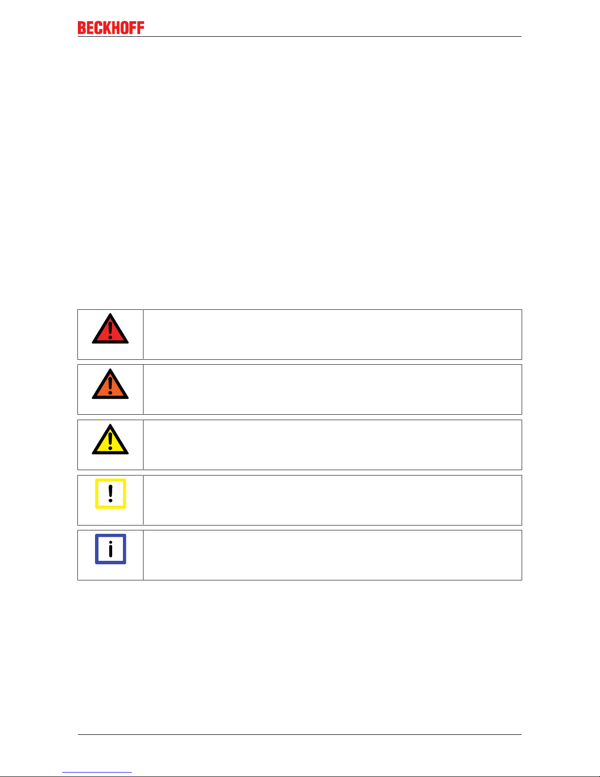
From 2014/01 the revision is shown on the outside of the IP20 terminals, see Fig. “EL5021 EL terminal,
standard IP20 IO device with batch number and revision ID (since 2014/01)”.
• The type, version and revision are read as decimal numbers, even if they are technically saved in
hexadecimal.
Identification number
Beckhoff EtherCAT devices from the different lines have different kinds of identification numbers:
Production lot/batch number/serial number/date code/D number
The serial number for Beckhoff IO devices is usually the 8-digit number printed on the device or on a sticker.
The serial number indicates the configuration in delivery state and therefore refers to a whole production
batch, without distinguishing the individual modules of a batch.
Structure of the serial number: KKYYFFHH
KK - week of production (CW, calendar week)
YY - year of production
FF - firmware version
HH - hardware version
Example with
Ser. no.: 12063A02: 12 - production week 12 06 - production year 2006 3A - firmware version 3A 02 hardware version 02
Exceptions can occur in the IP67 area, where the following syntax can be used (see respective device
documentation):
Syntax: D ww yy x y z u
Page 10
Foreword
EK110x, EK15xx10 Version: 3.6
D - prefix designation
ww - calendar week
yy - year
x - firmware version of the bus PCB
y - hardware version of the bus PCB
z - firmware version of the I/O PCB
u - hardware version of the I/O PCB
Example: D.22081501 calendar week 22 of the year 2008 firmware version of bus PCB: 1 hardware version
of bus PCB: 5 firmware version of I/O PCB: 0 (no firmware necessary for this PCB) hardware version of I/O
PCB: 1
Unique serial number/ID, ID number
In addition, in some series each individual module has its own unique serial number.
See also the further documentation in the area
• IP67: EtherCAT Box
• Safety: TwinSafe
• Terminals with factory calibration certificate and other measuring terminals
Examples of markings
Fig.1: EL5021 EL terminal, standard IP20 IO device with batch number and revision ID (since 2014/01)
Fig.2: EK1100 EtherCAT coupler, standard IP20 IO device with batch number
Page 11
Foreword
EK110x, EK15xx 11Version: 3.6
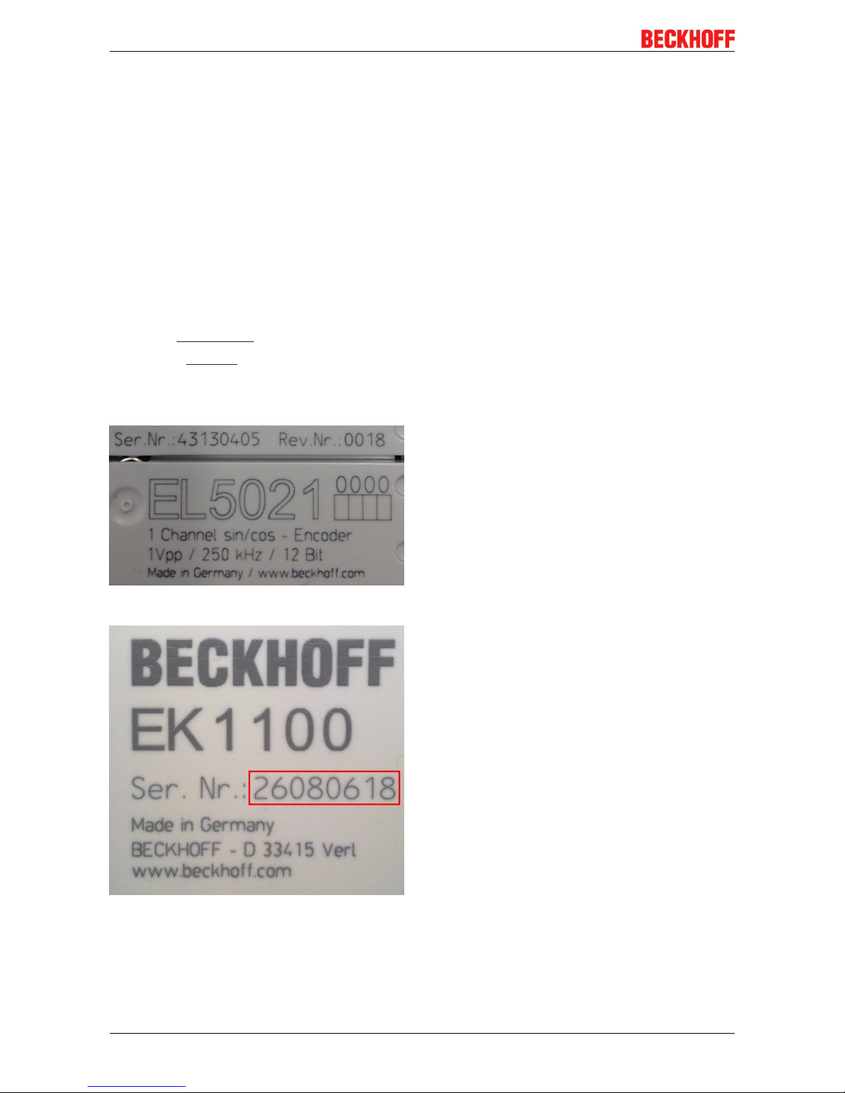
Fig.3: CU2016 switch with batch number
Fig.4: EL3202-0020 with batch numbers 26131006 and unique ID-number 204418
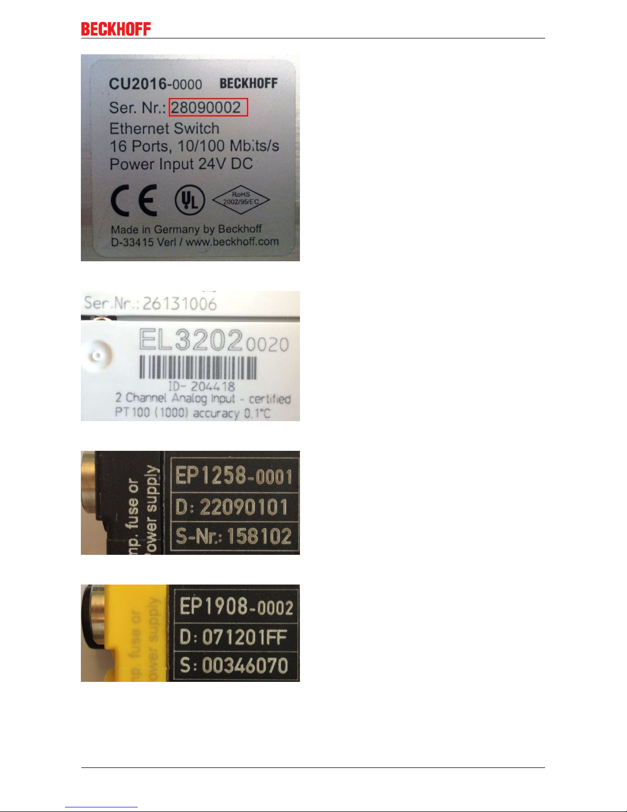
Fig.5: EP1258-00001 IP67 EtherCAT Box with batch number 22090101 and unique serial number 158102
Fig.6: EP1908-0002 IP67 EtherCAT Safety Box with batch number 071201FF and unique serial number
00346070
Page 12
Foreword
EK110x, EK15xx12 Version: 3.6
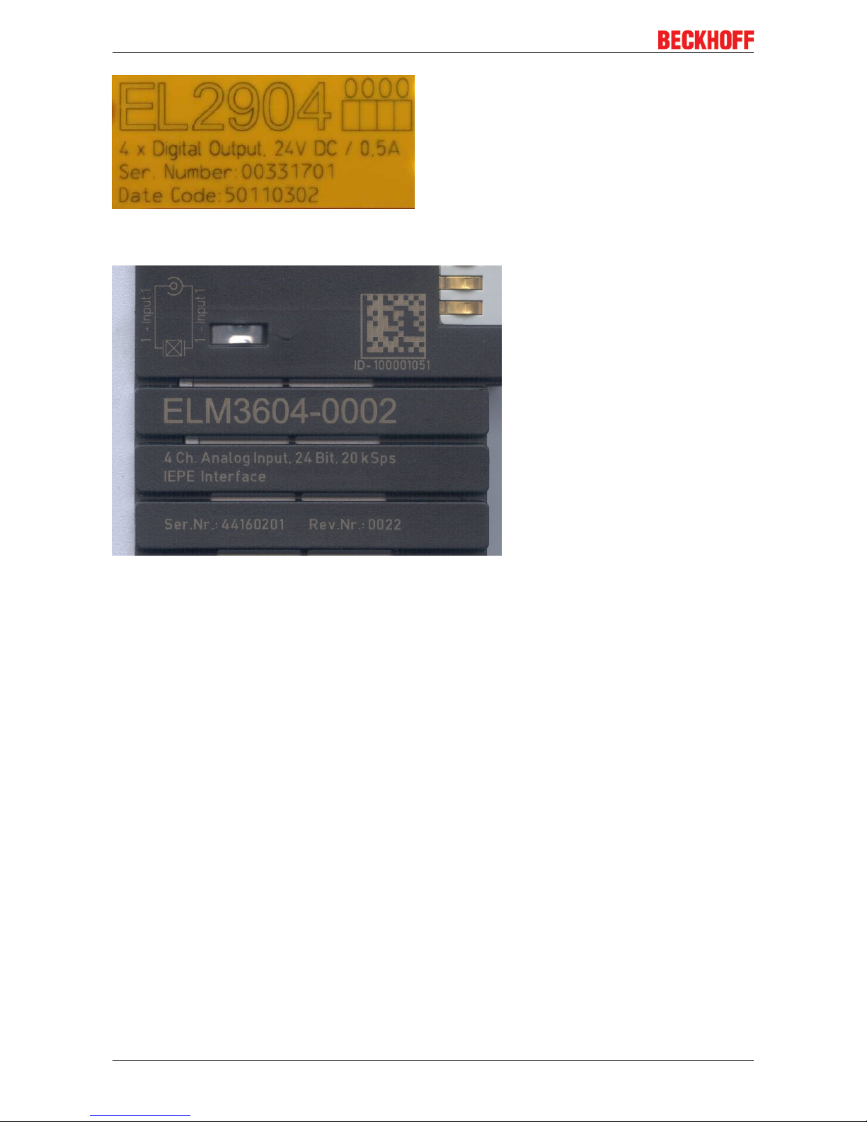
Fig.7: EL2904 IP20 safety terminal with batch number/date code 50110302 and unique serial number
00331701
Fig.8: ELM3604-0002 terminal with ID number (QR code) 100001051 and unique serial number 44160201
Page 13
Product overview
EK110x, EK15xx 13Version: 3.6
2 Product overview
2.1 Overview of EtherCAT couplers
An EtherCAT coupler is required in order to connect EtherCAT Terminals with E-bus-communication (series
ELxxxx, ESxxxx, EMxxxx) to an EtherCAT network. This coupler relays the communication from the higherlevel EtherCAT network to the terminals, or functions as a master itself and generates telegrams. Beckhoff
offers different components for different application scenarios.
The selection of the correct coupler depends on the following criteria:
• is a local small controller needed?
• is the coupler to be connected via copper cable or optical fiber cable?
• is the coupler to be addressed via IP or is it located in the unswitched network?
• is the coupler to be controlled via EAP (EtherCAT Automation Protocol) or EtherCAT Device Protocol?
• required protection class: IP20 or higher?
• is the coupler to be plugged in at different places at the network using the HotConnect technique?
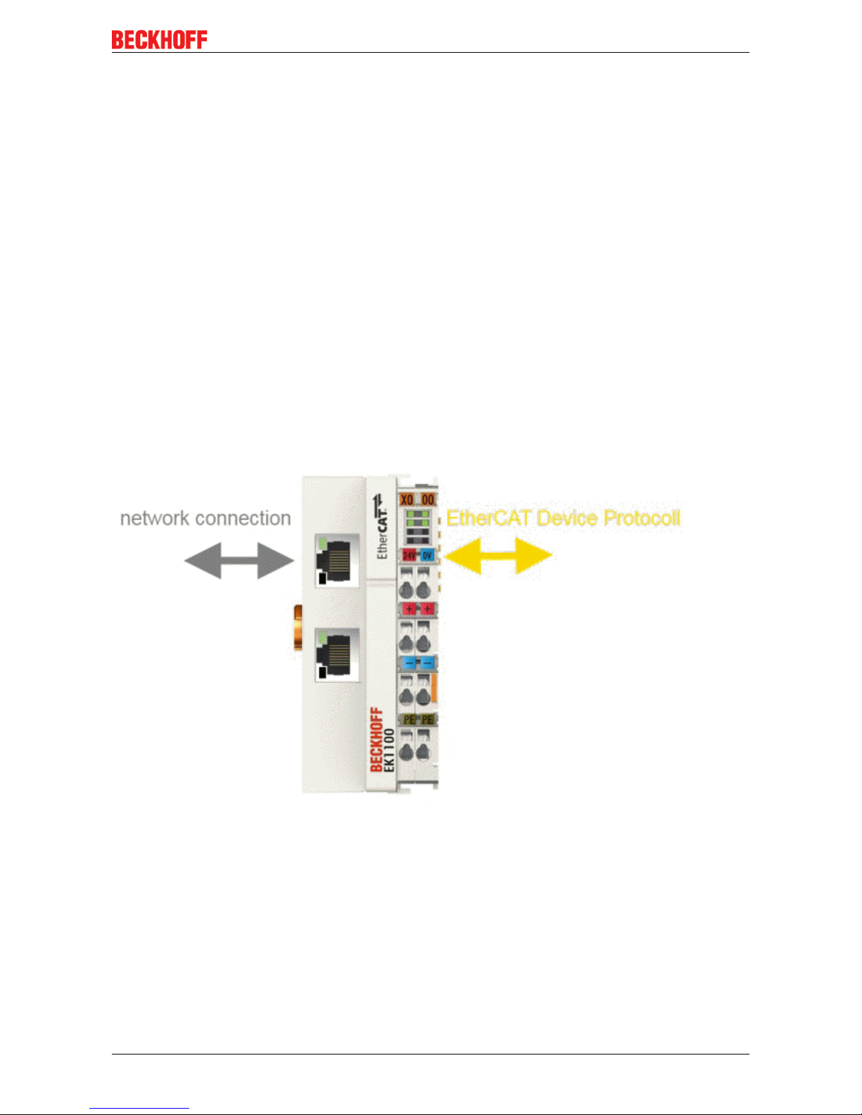
A coupler connects the added terminals to the right; it can be connected to the higher level network to the
left. Couplers that support the EtherCAT Device Protocol ‘to the left’ must be connected there to an
EtherCAT master.
Fig.9: EtherCAT coupler communication diagram
The following features overview can be used for selection (Beckhoff EtherCAT couplers):
Page 14

Product overview
EK110x, EK15xx14 Version: 3.6
Characteristic EK1100 EK1101
EK1101-0080
EK1501 EK1501-0010 EK1541
Protection class IP20 IP20 IP20 IP20 IP20
Higher level
network technology
100 MBit FastEthernet
(100BASE-TX)
100 MBit FastEthernet
(100BASE-TX)
100 MBit FastEthernet
(100BASE-FX)
100 MBit FastEthernet
(100BASE-FX)
100 MBit FastEthernet
(100BASE-FX)
POF
Higher level
network - max. connection
length
100 m 100 m 2 km 20 km 50m
Higher level
network connection technology
RJ45 RJ45 SC duplex
Multi-mode optical
fiber cable
SC duplex
Single-mode optical fiber cable
Versatile Link
POF duplex connector
Polymeric Optical
Fiber
higher-level
network protocol
EtherCAT Device
Protocol
(formerly Direct
Mode)
EtherCAT Device
Protocol
(formerly Direct
Mode)
EtherCAT Device
Protocol
(formerly Direct
Mode)
EtherCAT Device
Protocol
(formerly Direct
Mode)
EtherCAT Device
Protocol
(formerly Direct
Mode)
integrated PLC - - - - -
supports HotConnect with address setting on the device
- yes
EK1101-0080:
Fast-Hot-Connect
yes yes yes
Note The EK1100 is the
"standard" coupler
for use directly on
the EtherCAT master.
Characteristic EK18xx EK9000 EKx000 EPxxxx CX8000
Protection class IP20 IP20 IP20 IP67 IP20
Higher level
network technology
100 MBit FastEthernet
(100BASE-TX)
100 MBit FastEthernet
(100BASE-TX)
diverse
see doc.
100 MBit FastEthernet
(100BASE-TX)
100 MBit FastEthernet
(100BASE-TX)
Higher level
network - max. connection
length
100 m 100 m see doc. 100 m 100 m
Higher level
network connection technology
RJ45 RJ45 see doc. M8 RJ45
higher-level
network protocol
EtherCAT Device
Protocol
(formerly Direct
Mode)
EAP see doc. EtherCAT Device
Protocol
(formerly Direct
Mode)
EtherCAT Device
Protocol
(formerly Direct
Mode)
integrated PLC - - - - yes
supports HotConnect with address setting on the device
- - - - -
Note The EK18xx de-
vices integrate a
coupler for application directly at the
EtherCAT master
and digital inputs
and outputs without
additional wiring.
The EK9000 can
be controlled in a
switched EtherCAT
network with directed IP addressing.
If the EK9000 is
provided with another fieldbus connection, this gives
rise to the appropriate EKx000 coupler.
Technologically,
each EP Box represents a self-contained EtherCAT
coupler with internally added I/O
functions.
The CX8000 appears to the higher
level EtherCAT
network as an
EtherCAT slave
while at the same
time managing its
attached I/Os as a
master.
Page 15
Product overview
EK110x, EK15xx 15Version: 3.6
2.2 Coupler with RJ45 connection
2.2.1 EK1100
2.2.1.1 EK1100 - Introduction
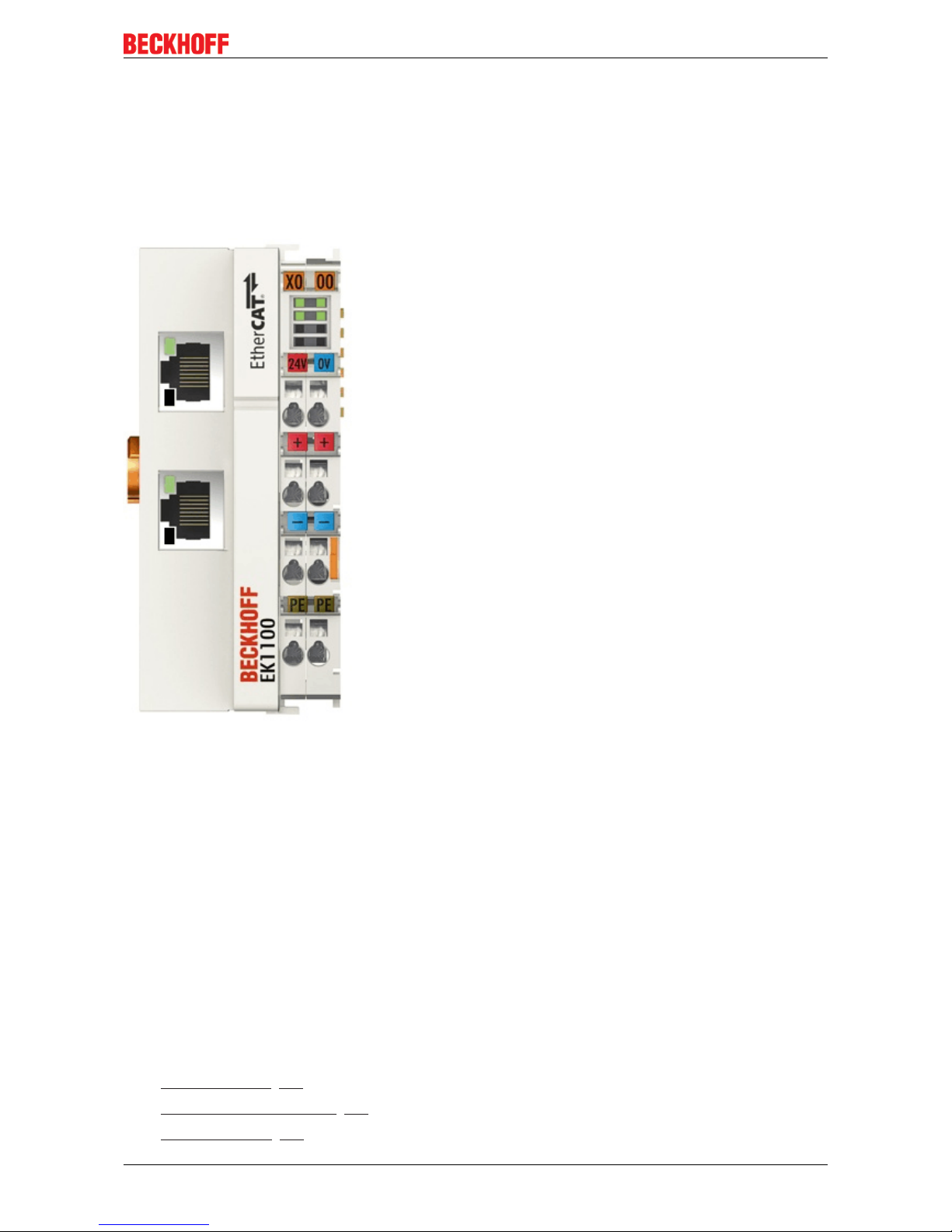
EK1100 EtherCAT Coupler
The EK1100 coupler connects the EtherCAT Device Protocol with the EtherCAT Terminals (ELxxxx/ESxxxx/
EMxxxx). One station consists of a coupler, any number of EtherCAT Terminals and a bus end terminal, e.g.
EL9011.
The coupler converts the telegrams from Ethernet 100BASE-TX to E-bus signal representation in passing
with minimum latency The coupler is connected to the network via the upper Ethernet interface. The lower
RJ-45 socket may be used to connect further EtherCAT devices in the same strand.
The coupler supplies the connected terminals with the necessary E-bus current for communication. The
coupler can supply a maximum of 5V/2A. Power feed terminals (e.g. EL9410) must be integrated if more
current is required.
In the EtherCAT network, the EK1100 coupler can be installed anywhere in the Ethernet signal transfer
section (100BASE-TX). The coupler thereby processes exclusively unaddressed MAC Broadcast telegrams
of the type EtherCAT Device Protocol from the EtherCAT master. Since directed addressing via MAC
Unicast or IP addressing is not used, neither a switch nor a router can be used.
Quick links
• EtherCAT basics [}31]
• Configuration instructions [}56]
• Diagnostic LEDs [}66]
Page 16

Product overview
EK110x, EK15xx16 Version: 3.6
2.2.1.2 EK1100 - Technical data
Technical data EK1100
Task within the EtherCAT system Coupling of EtherCAT Terminals (ELxxxx) to
100BASE-TX EtherCAT networks
Number of EtherCAT Terminals Up to 65535 in the overall system
Number of peripheral signals max. 4.2GB addressable IO points
Transmission medium at least Ethernet CAT-5 cable
Cable length between two Bus Couplers max. 100m (100BASE-TX)
Protocol / Baud rate EtherCAT Device Protocol / 100MBaud
HotConnect no
Delay typical 1µs
Bus connection 2 x RJ45
Power supply 24VDC (-15%/+20%)
Current consumption 70mA + (E-bus current)/4
E-bus power supply (5 V)
(at higher current consumption the EL9410 power
feed terminal can be used in addition)
max. 2000mA (-25°C ... +55°C)
max. 1000mA (> +55°C)
Power contacts max. 24VDC, max. 10A
Electrical isolation 500V (power contact/supply voltage/EtherCAT)
Dimensions (W x H x D) approx. 44mm x 100mm x 68mm
Weight approx. 105g
Permissible ambient temperature range during
operation
-25°C ... +60°C
Permissible ambient temperature range during
storage
-40°C ... + 85°C
Permissible relative humidity 95%, no condensation
Mounting [}37]
on 35mm mounting rail conforms to EN 60715
Vibration/shock resistance conforms to EN 60068-2-6/EN 60068-2-27,
see also Installation instructions [}40] for terminals
with increased mechanical load capacity
EMC immunity/emission conforms to EN 61000-6-2 / EN 61000-6-4
Protection class IP20
Installation position variable
Approval CE
ATEX [}54]
cULus [}52]
Page 17
Product overview
EK110x, EK15xx 17Version: 3.6
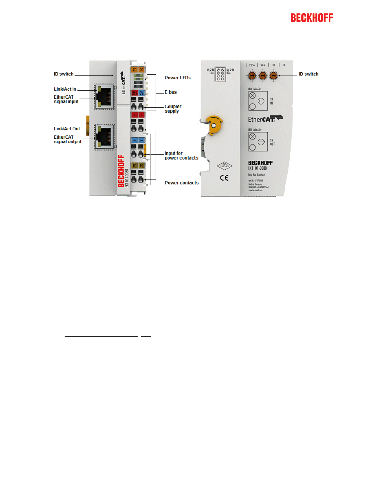
2.2.2 EK1101, EK1101-xxxx
2.2.2.1 EK1101 - Introduction
EK1101 EtherCAT coupler with ID switch
The EK1101 coupler connects the EtherCAT Device Protocol with the EtherCAT Terminals (ELxxxx/ESxxxx/
EMxxxx). One station consists of a coupler, any number of EtherCAT Terminals and a bus end terminal, e.g.
EL9011.
The coupler converts the telegrams from Ethernet 100BASE-TX to E-bus signal representation in passing
with minimum latency The coupler is connected to the network via the upper Ethernet interface. The lower
RJ-45 socket may be used to connect further EtherCAT devices in the same strand.
The coupler supplies the connected terminals with the necessary E-bus current for communication. The
coupler can supply a maximum of 5 V/2 A. Power feed terminals (e.g. EL9410) must be integrated if more
current is required.
In the EtherCAT network, the coupler can be installed anywhere in the Ethernet signal transfer section
(100BASE-TX). The coupler thereby processes exclusively unaddressed MAC Broadcast telegrams of the
type EtherCAT Device Protocol from the EtherCAT master. Since directed addressing via MAC Unicast or IP
addressing is not used, neither a switch nor a router can be used.
The EK1101 supports the HotConnect procedure, see EtherCAT documentation. The characteristics of the
EK1101 in relation to this are:
• ID can be set on the device via 3 rotary selector switches within the range 0 to 4095 (hexadecimal)
• the ID is readable online by the EtherCAT master via the process data
• if the EtherCAT master supports HotConnect, then an I/O group can be adopted dynamically into the
EtherCAT communication. This group can then be located at any position within the EtherCAT network.
Variable topologies are therefore easily implementable.
Quick links
• EtherCAT basics [}31]
• Configuration instructions
• Diagnostic LEDs [}66]
Page 18
Product overview
EK110x, EK15xx18 Version: 3.6
2.2.2.2 EK1101-0080 - Introduction
EK1101-0080 EtherCAT coupler with ID switch
The EK1101-0080 EtherCAT coupler with Fast Hot Connect technology is an extension of the EK1101
coupler.
Hot Connect is an EtherCAT feature for changing topologies through direct coupling or uncoupling during
operation. Coupled EtherCAT components are already quickly linked to the data communication after
connection as standard. Fast hot-connect technology further reduces the connection time significantly,
enabling even faster tool changes. Fast hot-connect ports may only be connected to each other, which is
why they are specially identified.
The EK1101-0080 EtherCAT coupler with Fast Hot Connect is complemented by the EK1122-0080
EtherCAT junction with Fast Hot Connect.
Quick links
• EtherCAT basics [}31]
• Configuration instructions
• Notes on Fast Hot Connect [}19]
• Diagnostic LEDs [}66]
Page 19

Product overview
EK110x, EK15xx 19Version: 3.6
2.2.2.3 EK1101, EK1101-0080 - Technical data
Technical data EK1101 EK1101-0080
Task within the EtherCAT system Coupling of EtherCAT Terminals
(ELxxxx) to 100BASE-TX
EtherCAT networks
Coupling of EtherCAT Terminals
(ELxxxx) to 100BASE-TX
EtherCAT networks,
Fast Hot Connect technology
Number of EtherCAT Terminals up to 65535 in the overall system
Number of peripheral signals max. 4.2GB addressable IO points
Transmission medium at least Ethernet CAT-5 cable
Cable length between two Bus
Couplers
max. 100m (100BASE-TX)
Protocol / Baud rate EtherCAT Device Protocol / 100MBaud
HotConnect max. number of configurable IDs: 4096
Delay typical 1µs
Bus connection 2 x RJ45
Power supply 24VDC (-15%/+20%)
Current consumption 70mA + (E-bus current)/4
E-bus power supply (5 V)
depending on ambient temperature
(at higher current consumption the
EL9410 power feed terminal can be
used in addition)
max. 2000mA (-25°C ... +55°C)
max. 1000mA (> +55°C)
Power contacts max. 24VDC, max. 10A
Electrical isolation 500V (power contact/supply voltage/EtherCAT)
Dimensions (W x H x D) approx. 44mm x 100mm x 68mm
Weight approx. 105g
Permissible ambient temperature
range during operation
-25°C ... +60°C
Permissible ambient temperature
range during storage
-40°C ... + 85°C
Permissible relative humidity 95%, no condensation
Mounting [}37]
on 35mm mounting rail conforms to EN 60715
Vibration/shock resistance conforms to EN 60068-2-6 / EN 60068-2-27
EMC immunity/emission conforms to EN 61000-6-2 / EN 61000-6-4
Protection class IP20
Installation position variable
Approval CE
ATEX [}54]
cULus [}52]
2.2.2.4 Notes re. EtherCAT Fast Hot Connect technology
EtherCAT components that support Fast Hot Connect enable a faster fieldbus boot up following the
establishment of a connection. The boot up depends in detail on the number of devices, the topology and
activated Distributed Clocks. Whereas the normal establishment of a connection and communication takes
several seconds, less than 1 second is possible with FHC components.
Properties and system behavior
• Fast Hot Connect is supported from TwinCAT 2.11R3 Build 2221.
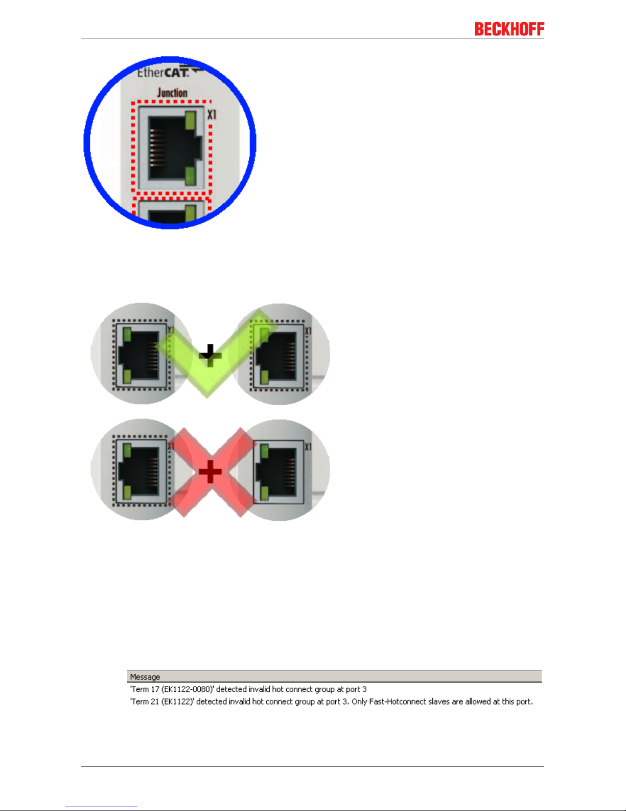
• Fast Hot Connect ports are specially marked.
Page 20
Product overview
EK110x, EK15xx20 Version: 3.6
Fig.10: Identification of FHC port at EK1122-0080 and EK1101-0080
• Standard EtherCAT devices may not be connected to Fast Hot Connect ports. This is to be ensured by
measures on the application side, which is easy to implement by means of the topology change that is
usually carried out mechanically in such applications.
Fig.11: Recommended combination of Ethernet ports
• If corresponding ports are nevertheless connected, a power reset of the devices involved (branch
terminal and coupler/box) is required.
• With Fast Hot Connect devices the establishment of an Ethernet connection is accelerated compared
to the normal Fast Ethernet connection.
If in addition the use of Distributed Clocks functions is omitted in the entire topology, then the
resynchronization time of the components is also dispensed with. Group boot up of < 1 second is then
possible, from plugging in the Ethernet connection to the OP state.
• An incorrect port allocation is detected in the TwinCAT ADS Logger
Page 21
Product overview
EK110x, EK15xx 21Version: 3.6
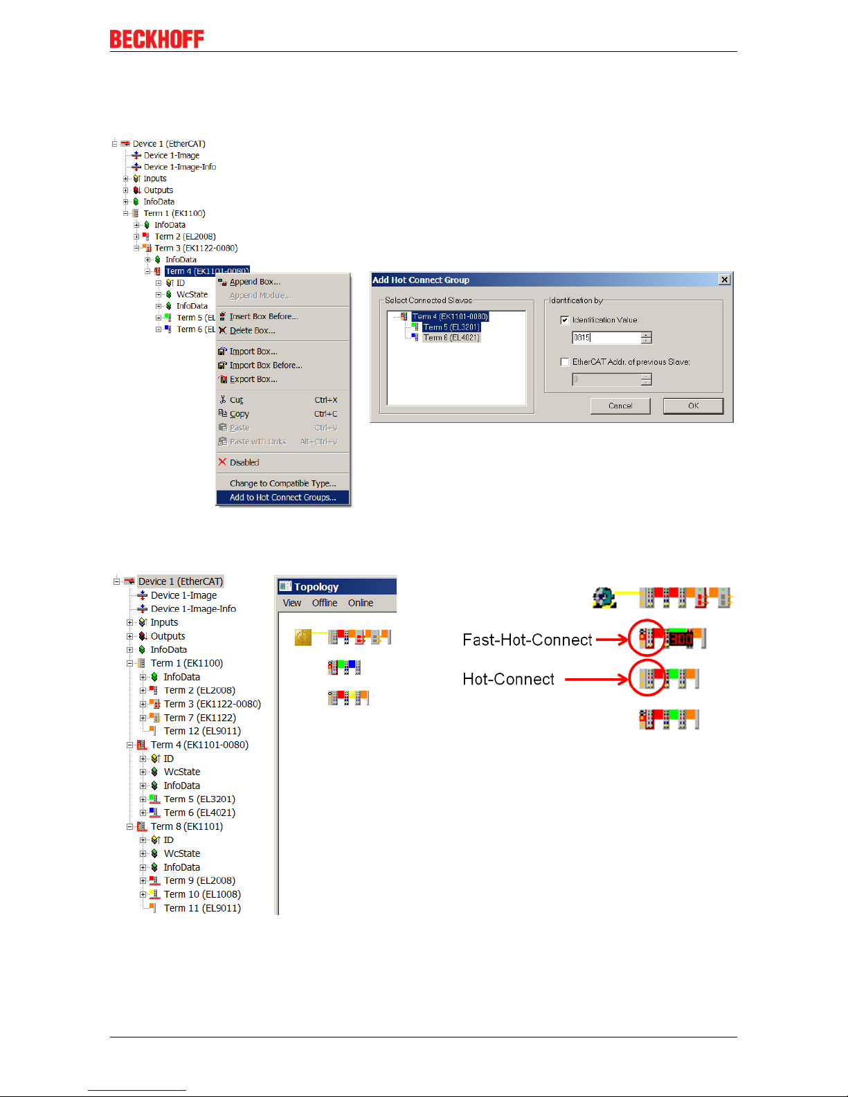
Configuration
The configuration of Fast Hot Connect groups in the TwinCAT System Manager takes place in exactly the
same way as Hot Connect groups, specifying the associated group ID.
Fig.12: Configuration of a Fast Hot Connect group
Corresponding Fast Hot Connect ports are marked red in the TwinCAT System Manager.
Fig.13: Marking in the TwinCAT System Manager
A configuration of FHC groups is possible only if at least 1 corresponding junction is present e.g.
EK1122-0080.
Page 22
Product overview
EK110x, EK15xx22 Version: 3.6
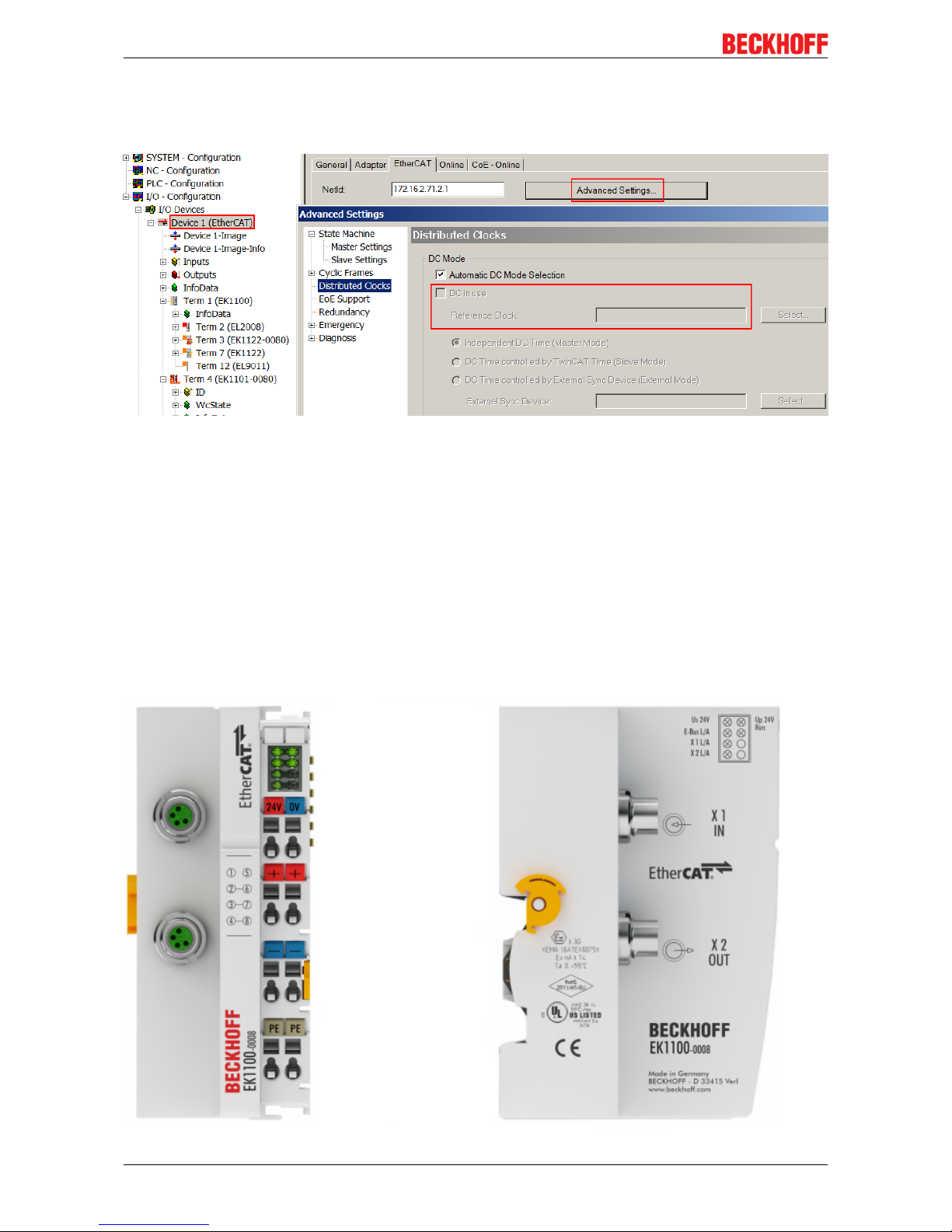
Distributed Clocks
If no Distributed Clocks functions are used, this is visible in the master settings by the absence of "DC in
use":
Fig.14: DC master setting
This setting is automatically selected by the System Manager if there are no EtherCAT slaves in the
configuration in which Distributed Clocks is activated. "DC in use" should not be randomly deactivated by the
user, because otherwise these devices will no longer function.
2.3 Coupler with M8 connection
2.3.1 EK1100-0008
2.3.1.1 EK1100-0008 - Introduction
Page 23

Product overview
EK110x, EK15xx 23Version: 3.6
EtherCAT coupler EK1100-0008 (M8 connection)
The EK1100-0008 coupler connects EtherCAT with the EtherCAT Terminals (ELxxxx/ESxxxx). One station
consists of a coupler EK1100-0008, any number of EtherCAT Terminals and a bus end terminal.
The coupler converts the telegrams from Ethernet 100BASE-TX to E-bus signal representation. Compared to
EK1100 the EK1100-0008 has two M8 sockets instead of two RJ45 sockets, compatible to the ones of the
EtherCAT-Boxes.
The upper Ethernet interface is used to connect the coupler to the network; the lower M8 socket serves for
the optional connection of further EtherCAT devices in the same strand.
The coupler supplies the connected terminals with the necessary E-bus current for communication. The
coupler can supply a maximum of 5V/2A. Power feed terminals (e.g. EL9410) must be integrated if more
current is required.
In the EtherCAT network, the EK1100-0008 coupler can be installed anywhere in the Ethernet signal transfer
section (100BASE-TX) except onto the switch directly. By using respective powerful Ethernet cables e.g.
ZK1090-3131-1xxx distances of 100m are also possible via M8.
Quick links
• EtherCAT basics [}31]
• Configuration instructions [}56]
• Diagnostic LEDs [}66]
Page 24

Product overview
EK110x, EK15xx24 Version: 3.6
2.3.1.2 EK1100-0008 - Technical data
Technical data EK1100-0008
Task within the EtherCAT system Coupling of EtherCAT Terminals (ELxxxx) to
100BASE-TX EtherCAT networks
Number of EtherCAT Terminals up to 65535 in the overall system
Transmission medium at least EtherCAT CAT-5 cable
Cable length between two Bus Couplers max. 100m (100BASE-TX)
Transfer rate 100MBaud
Configuration Not required
Delay typical 1µs
Bus interface 2 x M8
Power supply 24VDC (-15%/+20%)
Current consumption from US 70mA + (∑ E-Bus-Strom/4)
Current consumption from UP Load
Power supply E-bus max. 2000mA (-25°C ... +55°C)
Power contacts max. 24VDC, max. 10A
Electrical isolation 500V (power contact/supply voltage/EtherCAT)
Dimensions (W x H x D) approx. 44mm x 100mm x 68mm
Weight approx. 105g
Permissible ambient temperature range during
operation
-25°C ... +60°C
Permissible ambient temperature range during
storage
-40°C ... + 85°C
Permissible relative humidity 95%, no condensation
Mounting [}37]
on 35 mm mounting rail conforms to EN 60715
Vibration/shock resistance conforms to EN 60068-2-6/EN 60068-2-27,
see also Installation instructions [}40] for terminals
with increased mechanical load capacity
EMC immunity/emission conforms to EN 61000-6-2 / EN 61000-6-4
Protection class IP20
Installation position variable
Approval CE
ATEX [}54]
cULus [}52]
Page 25
Product overview
EK110x, EK15xx 25Version: 3.6
2.4 Coupler with optical fiber connection
2.4.1 EK1501
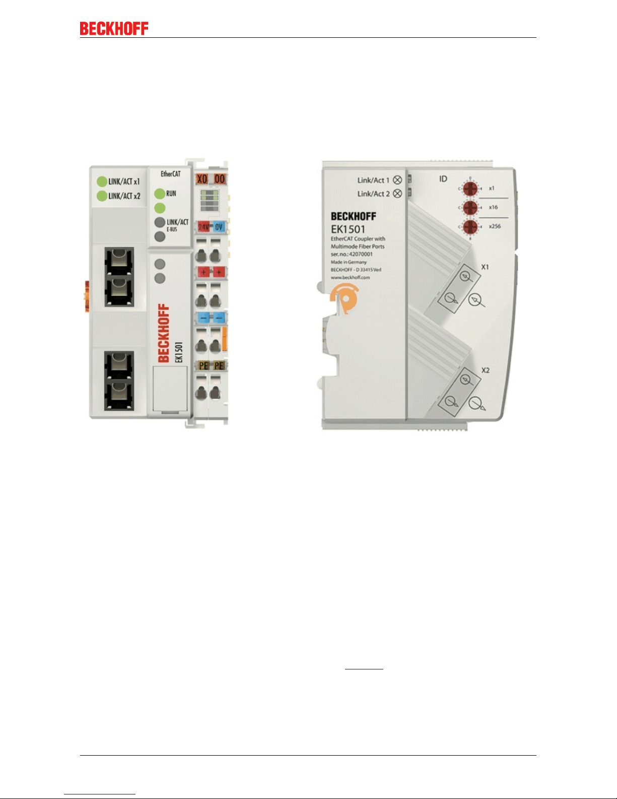
2.4.1.1 EK1501 - Introduction
EK1501 EtherCAT coupler with ID switch, multimode optical fiber connection
The EK1501 coupler connects the EtherCAT Device Protocol with the EtherCAT Terminals (ELxxxx/ESxxxx/
EMxxxx). One station consists of a coupler, any number of EtherCAT Terminals and a bus end terminal, e.g.
EL9011.
The coupler converts the telegrams from Ethernet 100BASE-FX to E-bus signal representation in passing
with minimum latency The upper Ethernet interface is used to connect the coupler to the network; the lower
SC socket serves for the optional connection of further EtherCAT devices in the same strand.
The coupler supplies the connected terminals with the necessary E-bus current for communication. The
coupler can supply a maximum of 5V/2A. Power feed terminals (e.g. EL9410) must be integrated if more
current is required.
In the EtherCAT network, the coupler is used at an arbitrary place in the Ethernet signal transmission range
(100BASE-FX). The coupler thereby processes exclusively unaddressed MAC Broadcast telegrams of the
type EtherCAT Device Protocol from the EtherCAT master. Since directed addressing via MAC Unicast or IP
addressing is not used, neither a switch nor a router can be used.
The multimode glass fiber connection enables distances of up to 2 km between two couplers.
The coupler supports the HotConnect technique; see the basic EtherCAT documentation regarding this. The
characteristics of the EK1501 in relation to this are:
• ID can be set on the device via 3 rotary selector switches within the range 0 to 4095 (hexadecimal)
• the ID is readable online by the EtherCAT master via the process data
Page 26

Product overview
EK110x, EK15xx26 Version: 3.6
• if the EtherCAT master supports HotConnect, then an I/O group can be adopted dynamically into the
EtherCAT communication. This group can then be located at any position within the EtherCAT network.
Variable topologies are therefore easily implementable.
Quick links
• EtherCAT basics [}31]
• Application notes [}56]
• Diagnostic LEDs [}66]
2.4.1.2 EK1501 - Technical data
Technical data EK1501
Task within the EtherCAT system Coupling of EtherCAT Terminals (ELxxxx) to
100BASE-FX EtherCAT networks
Number of EtherCAT Terminals up to 65535 in the overall system
Number of peripheral signals max. 4.2GB addressable IO points
Transmission medium Multimode glass fiber (MM)
Cable length between two Bus Couplers max. 2km (100BASE-FX)
Transceiver wavelength typically 1300nm
Protocol / Baud rate EtherCAT Device Protocol / 100MBaud
HotConnect max. number of configurable IDs: 4096
Delay typical 1µs
Bus connection 2 x SC Duplex
Power supply 24VDC (-15%/+20%)
Current consumption 130mA + (E-bus current)/4
E-bus power supply (5 V)
depending on ambient temperature
(at higher current consumption the EL9410 power
feed terminal can be used in addition)
max. 2000mA (-25°C ... +55°C)
max. 1000mA (> +55°C)
Power contacts max. 24VDC, max. 10A
Electrical isolation 500 V (power contact/supply voltage/EtherCAT)
Dimensions (W x H x D) approx. 49mm x 100mm x 70mm
Weight approx. 190g
Permissible ambient temperature range during
operation
-25°C ... +60°C (extended temperature range)
Permissible ambient temperature range during
storage
-40°C ... + 85°C
Permissible relative humidity 95%, no condensation
Mounting [}37]
on 35 mm mounting rail conforms to EN 60715
Vibration/shock resistance conforms to EN 60068-2-6 / EN 60068-2-27
EMC immunity/emission conforms to EN 61000-6-2 / EN 61000-6-4
Protection class IP20
Installation position variable
Approval CE
ATEX [}54]
cULus [}52]
Page 27

Product overview
EK110x, EK15xx 27Version: 3.6
2.4.2 EK1501-0010
2.4.2.1 EK1501-0010 - Introduction
EK1501-0010 EtherCAT coupler with ID switch, single-mode optical fiber connection
The EK1501-0010 coupler differs from the EK1501 only in the transceiver used. Transmission ranges of up
to 20 km can be attained with the single-mode technique using appropriate optical fiber cables.
An attenuation budget of 10 dBm is available between the EK1501-0010 and the associated EK1521-0010
branch. The following factors can be taken as a basis for the estimation of the attenuation:
• Two SC plug connectors: 0.25 dBm each
• typical optical fiber cable with 0.4 dB/km attenuation
The sum of all attenuations may not exceed 10 dBm. The installed fiber optic section is to be validated by
measurement if necessary.
Quick links
• EtherCAT basics [}31]
• Application notes [}56]
• Diagnostic LEDs [}66]
Page 28

Product overview
EK110x, EK15xx28 Version: 3.6
2.4.2.2 EK1501-0010 - Technical data
Technical data EK1501-0010
Task within the EtherCAT system Coupling of EtherCAT Terminals (ELxxxx) to
100BASE-FX EtherCAT networks
Number of EtherCAT Terminals up to 65535 in the overall system
Number of peripheral signals max. 4.2GB addressable IO points
Transmission medium Single mode glass fiber (SM)
Cable length between two Bus Couplers max. 20km (100BASE-FX)
Transceiver wavelength typically 1300nm
Protocol / Baud rate EtherCAT Device Protocol / 100MBaud
HotConnect max. number of configurable IDs: 4096
Delay typical 1µs
Bus connection 2 x SC Duplex
Power supply 24VDC (-15%/+20%)
Current consumption 150mA + (E-bus current)/4
E-bus power supply (5 V)
depending on ambient temperature
(at higher current consumption the EL9410 power
feed terminal can be used in addition)
max. 2000mA (-25°C ... +55°C)
max. 1000mA (> +55°C)
Power contacts max. 24VDC, max. 10A
Electrical isolation 500V (power contact/supply voltage/EtherCAT)
Dimensions (W x H x D) approx. 49mm x 100mm x 70mm
Weight approx. 190g
Permissible ambient temperature range during
operation
-25°C ... +60°C (extended temperature range)
Permissible ambient temperature range during
storage
-40°C ... + 85°C
Permissible relative humidity 95%, no condensation
Mounting [}37]
on 35mm mounting rail conforms to EN 60715
Vibration/shock resistance conforms to EN 60068-2-6 / EN 60068-2-27
EMC immunity/emission conforms to EN 61000-6-2 / EN 61000-6-4
Protection class IP20
Installation position variable
Approval CE
ATEX [}54]
cULus [}52]
Page 29
Product overview
EK110x, EK15xx 29Version: 3.6
2.5 Coupler with POF connection
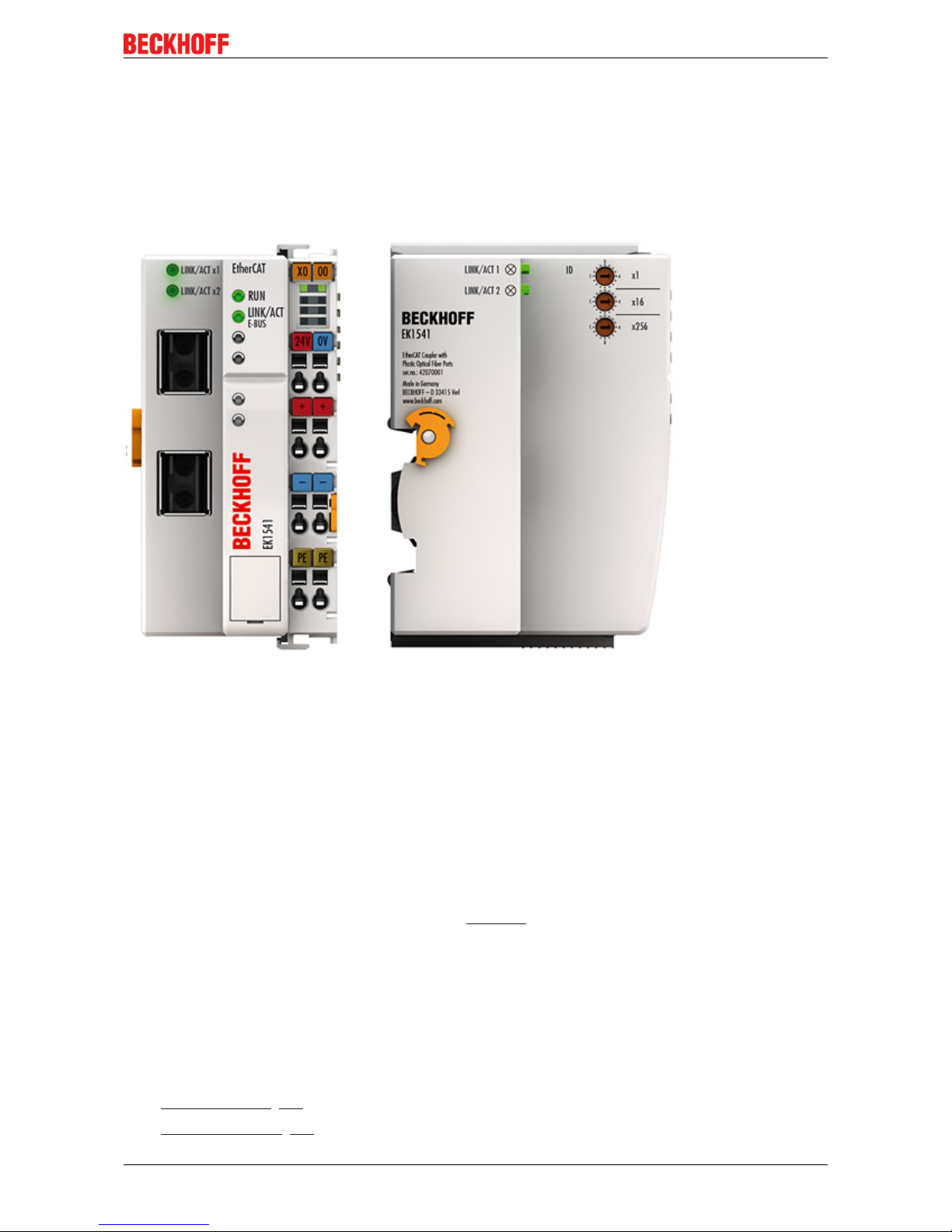
2.5.1 EK1541
2.5.1.1 EK1541 - Introduction
EK1541 EtherCAT coupler with ID switch, POF connection
The EK1541 Coupler connects EtherCAT with the EtherCAT Terminals (ELxxxx). A station consists of an
EK1541 coupler, any number of EtherCAT Terminals, an EL9011 bus end cap or an EK1110 EtherCAT
extender.
The coupler converts the telegrams from Ethernet 100BASE-FX-POF physics to E-bus signal representation
in passing with minimum latency The Polymeric Optical Fiber (POF) connection enables distances of up to
50 m between two couplers. Unlike the glass fiber, the POF fiber is easily wireable in the field. The EK1541
has three hexadecimal ID switches for assigning an ID to a group of EtherCAT components.
The coupler supplies the connected terminals with the necessary E-bus current for communication. The
coupler can supply a maximum of 5V/2A. Power feed terminals (e.g. EL9410) must be integrated if more
current is required.
The device supports the HotConnect procedure, see EtherCAT documentation. The characteristics of the
EK1541 in relation to this are:
• ID can be set on the device via 3 rotary selector switches within the range 0 to 4095 (hexadecimal)
• the ID is readable online by the EtherCAT master via the process data
• if the EtherCAT master supports HotConnect, then an I/O group can be adopted dynamically into the
EtherCAT communication. This group can then be located at any position within the EtherCAT network.
Variable topologies are therefore easily implementable.
Quick links
• EtherCAT basics [}31]
• Application notes [}59]
Page 30

Product overview
EK110x, EK15xx30 Version: 3.6
• Diagnostic LEDs [}66]
2.5.1.2 EK1541 - Technical data
Technical data EK1541
Task within the EtherCAT system Coupling of EtherCAT Terminals (ELxxxx) to
100BASE-FX EtherCAT POF networks
Number of EtherCAT Terminals up to 65534 in the overall system
Number of peripheral signals max. 4.2GB addressable IO points
Transmission medium Polymeric Optical Fiber
Cable length between two Bus Couplers max. 50m (100BASE-FX-POF)
Transceiver wavelength 650nm
Laser class 1, see note [}71]
Protocol / Baud rate EtherCAT Device Protocol / 100MBaud
HotConnect max. number of configurable IDs: 4096
Delay typical 1µs
Bus connection 2 x versatile link for POF duplex connector
(connector set ZS1090-0008)
Power supply 24VDC (-15%/+20%)
Input current 130mA + (total E-bus current)/4
Current consumption 24 V DC typ. 70mA
E-Bus current consumption -
E-bus power supply (5 V)
depending on ambient temperature
(at higher current consumption the EL9410 power
feed terminal can be used in addition)
max. 2000mA (-25°C ... +55°C)
max. 1000mA (> +55°C)
Power contacts max. 24VDC, max. 10A
Electrical isolation 500V (power contact/supply voltage/EtherCAT)
Dimensions (W x H x D) approx. 49mm x 100mm x 70mm
Weight approx. 190g
Permissible ambient temperature range during
operation
-25°C ... +60°C (extended temperature range)
Permissible ambient temperature range during
storage
-40°C ... + 85°C
Permissible relative humidity 95%, no condensation
Mounting [}37]
on 35 mm mounting rail conforms to EN 60715
Vibration/shock resistance conforms to EN 60068-2-6 / EN 60068-2-27
EMC immunity/emission conforms to EN 61000-6-2 / EN 61000-6-4
Protection class IP20
Installation position variable
Approval CE
cULus [}52]
Page 31

Basics
EK110x, EK15xx 31Version: 3.6
3 Basics
3.1 EtherCAT basics
Please refer to the chapter EtherCAT System Documentation for the EtherCAT fieldbus basics.
3.2 EtherCAT coupler port allocation
According to the EtherCAT specification, an ESC (EtherCAT Slave Controller, hardware processing unit of
the EtherCAT protocol) can have 1 to 4 ports, which it controls itself. Via an open port it can handle outgoing
and incoming Ethernet traffic.
The following figure shows the direction of data flow in a fully connected EK1100 (or EK1100-0008) as an
example:
Fig.15: Example: EK1100 / EK1100-0008 EtherCAT coupler with 3 ports
The port assignment in the case of the EK1101, EK1501 and EK1501-0010, EK1814 applies accordingly.
Page 32

Basics
EK110x, EK15xx32 Version: 3.6
Fig.16: Internal and external port assignment for Bus Coupler EK1100 and EK1100-0008
Frame processing sequence
The EtherCAT frame arriving at the EtherCAT signal input is passed on by Port 0 (A) to the EtherCAT
processing unit.
• The EtherCAT frame arrives at Port 1 (B) and the data frame departs via Port 1 (B) to the following slave in
the EtherCAT terminal network (if a slave is connected there and reports ‘Link’).
• After the arrival of the data frame at Port 1 (B) from the terminal network, this is passed on to Port 2 (C) and
leaves the coupler at the following EtherCAT output (if a slave is connected there and reports ‘Link’).
• The data frame arrives at Port 2 (C). This is now forwarded to port 0 (A) and leaves the EK1100 /
EK1100-0008 via the EtherCAT input.
Note
Processing of the data
The data in the EtherCAT datagrams are processed only between Ports 0 (A) and 3 (D) in
the EtherCAT processing unit. The non-implemented (internal) Port 3 (D) is considered to
be closed and passes on the datagram to Port 1 (B).
Page 33

Basics
EK110x, EK15xx 33Version: 3.6
3.3 EtherCAT State Machine
The state of the EtherCAT slave is controlled via the EtherCAT State Machine (ESM). Depending upon the
state, different functions are accessible or executable in the EtherCAT slave. Specific commands must be
sent by the EtherCAT master to the device in each state, particularly during the bootup of the slave.
A distinction is made between the following states:
• Init
• Pre-Operational
• Safe-Operational and
• Operational
• Boot
The regular state of each EtherCAT slave after bootup is the OP state.
Fig.17: States of the EtherCAT State Machine
Init
After switch-on the EtherCAT slave in the Init state. No mailbox or process data communication is possible.
The EtherCAT master initializes sync manager channels 0 and 1 for mailbox communication.
Pre-Operational (Pre-Op)
During the transition between Init and Pre-Op the EtherCAT slave checks whether the mailbox was initialized
correctly.
In Pre-Op state mailbox communication is possible, but not process data communication. The EtherCAT
master initializes the sync manager channels for process data (from sync manager channel 2), the FMMU
channels and, if the slave supports configurable mapping, PDO mapping or the sync manager PDO
assignment. In this state the settings for the process data transfer and perhaps terminal-specific parameters
that may differ from the default settings are also transferred.
Safe-Operational (Safe-Op)
During transition between Pre-Op and Safe-Op the EtherCAT slave checks whether the sync manager
channels for process data communication and, if required, the distributed clocks settings are correct. Before
it acknowledges the change of state, the EtherCAT slave copies current input data into the associated DPRAM areas of the EtherCAT slave controller (ECSC).
Page 34

Basics
EK110x, EK15xx34 Version: 3.6
In Safe-Op state mailbox and process data communication is possible, although the slave keeps its outputs
in a safe state, while the input data are updated cyclically.
Note
Outputs in SAFEOP state
The default set watchdog monitoring sets the outputs of the module in a safe state - depending on the settings in SAFEOP and OP - e.g. in OFF state. If this is prevented by deactivation of the watchdog monitoring in the module, the outputs can be switched or set
also in the SAFEOP state.
Operational (Op)
Before the EtherCAT master switches the EtherCAT slave from Safe-Op to Op it must transfer valid output
data.
In the Op state the slave copies the output data of the masters to its outputs. Process data and mailbox
communication is possible.
Boot
In the Boot state the slave firmware can be updated. The Boot state can only be reached via the Init state.
In the Boot state mailbox communication via the file access over EtherCAT (FoE) protocol is possible, but no
other mailbox communication and no process data communication.
3.4 CoE - Interface: notes
This device has no CoE.
Detailed information on the CoE interface can be found in the EtherCAT system documentation on the
Beckhoff website.
3.5 EKxxxx - Optional Distributed Clocks support
Basic principles Distributed Clocks (DC)
The EtherCAT Distributed Clocks system comprises local clocks that are integrated in the EtherCAT slaves
and are synchronized by the EtherCAT master via special datagrams. Not all EtherCAT slaves support the
Distributed Clocks procedure. It is only supported by slaves whose function requires it. In the TwinCAT
System Manager a slave indicates its DC capability by showing “DC” in the settings dialog.
Fig.18: DC tab for indicating the Distributed Clocks function
Once of these local clocks is the reference clock, based on which all other clocks are synchronized. See also
explanatory notes in the Basic EtherCAT documentation. The reference clock must be the first DC-capable
EtherCAT slave. By default TwinCAT therefore selects the first DC-capable device as reference clock. This is
shown (and can be modified by the user) under advanced properties of the EtherCAT master. The standard
setting should not be changed, except in cases where external synchronization is recommended in the
relevant documentation, for example.
Page 35

Basics
EK110x, EK15xx 35Version: 3.6
Fig.19: Advanced Distributed Clocks settings in the EtherCAT master
The figure shows how TwinCAT selects the EL1252 as reference clock by default, since the preceding
components do not support DC.
Settings EtherCAT device
System and infrastructure devices such as EK1100 or EK1122 couplers and junction etc. do not require
Distributed Clocks to function properly. Nevertheless, it may be topologically expedient to designate the first
coupler in an EtherCAT system as reference clock, for example. For this reason, from a certain level the
infrastructure components are able to operate as reference clocks, based on special configuration settings.
According to the following table (DC support from rev/firmware version), the components support activation
of distributed clocks:
Device XML revision in the configura-
tion
Serial number of the component
BK1150 from BK1150-0000-0016 from firmware 01: xxxx01yy
CU1128 from CU1128-0000-0000 from firmware 00: xxxx00yy
EK1100 from EK1100-0000-0017 from firmware 06: xxxx06yy
EK1101 from EK1101-0000-0017 from firmware 01: xxxx01yy
EK1501 from EK1501-0000-0017 from firmware 01: xxxx01yy
EK1501-0010 from EK1501-0010-0017 from firmware 02: xxxx02yy
EK1122 from EK1122-0000-0017 from firmware 01: xxxx02yy
EK1521 from EK1521-0000-0018 from firmware 03: xxxx03yy
EK1541 from EK1541-0000-0016 from firmware 01: xxxx01yy
EK1561 from EK1561-0000-0016 from firmware 01: xxxx01yy
EK1521-0010 from EK1521-0010-0018 from firmware 03: xxxx03yy
EK1814 from EK1814-0000-0016 from firmware 00: xxxx00yy
To ensure that TwinCAT uses such a component as DC reference clock, a manual intervention during the
configuration setup is required, as shown here using the EK1100 as an example.
The checkboxes “Cyclic Mode Enable” and “Use as potential Reference Clock” must be set.
Page 36

Basics
EK110x, EK15xx36 Version: 3.6
Fig.20: TwinCAT setting for using this component as reference clock
Note
Activation of Distributed Clocks support
The (synchronization) procedure described here is only successful for the components described above. The checkboxes can be set for other components, too, although the hardware does not support this function, unless specified in the respective documentation. In
particularly, please note that after commissioning the component may not be replaced with
a previous version without DC support.
Page 37

Mounting and wiring
EK110x, EK15xx 37Version: 3.6
4 Mounting and wiring
4.1 Instructions for ESD protection
Attention
Destruction of the devices by electrostatic discharge possible!
The devices contain components at risk from electrostatic discharge caused by improper
handling.
ü Please ensure you are electrostatically discharged and avoid touching the contacts of
the device directly.
a) Avoid contact with highly insulating materials (synthetic fibers, plastic film etc.).
b) Surroundings (working place, packaging and personnel) should by grounded probably,
when handling with the devices.
c) Each assembly must be terminated at the right hand end with an EL9011 bus end cap,
to ensure the protection class and ESD protection.
Fig.21: Spring contacts of the Beckhoff I/O components
4.2 Installation on mounting rails
WARNING
Risk of electric shock and damage of device!
Bring the bus terminal system into a safe, powered down state before starting installation,
disassembly or wiring of the Bus Terminals!
Page 38

Mounting and wiring
EK110x, EK15xx38 Version: 3.6
Assembly
Fig.22: Attaching on mounting rail
The Bus Coupler and Bus Terminals are attached to commercially available 35mm mounting rails (DIN rails
according to EN60715) by applying slight pressure:
1. First attach the Fieldbus Coupler to the mounting rail.
2. The Bus Terminals are now attached on the right-hand side of the Fieldbus Coupler. Join the components with tongue and groove and push the terminals against the mounting rail, until the lock clicks
onto the mounting rail.
If the Terminals are clipped onto the mounting rail first and then pushed together without tongue and
groove, the connection will not be operational! When correctly assembled, no significant gap should
be visible between the housings.
Note
Fixing of mounting rails
The locking mechanism of the terminals and couplers extends to the profile of the mounting
rail. At the installation, the locking mechanism of the components must not come into conflict with the fixing bolts of the mounting rail. To mount the mounting rails with a height of
7.5mm under the terminals and couplers, you should use flat mounting connections (e.g.
countersunk screws or blind rivets).
Page 39

Mounting and wiring
EK110x, EK15xx 39Version: 3.6
Disassembly
Fig.23: Disassembling of terminal
Each terminal is secured by a lock on the mounting rail, which must be released for disassembly:
1. Pull the terminal by its orange-colored lugs approximately 1cm away from the mounting rail. In doing
so for this terminal the mounting rail lock is released automatically and you can pull the terminal out of
the bus terminal block easily without excessive force.
2. Grasp the released terminal with thumb and index finger simultaneous at the upper and lower grooved
housing surfaces and pull the terminal out of the bus terminal block.
Connections within a bus terminal block
The electric connections between the Bus Coupler and the Bus Terminals are automatically realized by
joining the components:
• The six spring contacts of the K-Bus/E-Bus deal with the transfer of the data and the supply of the Bus
Terminal electronics.
• The power contacts deal with the supply for the field electronics and thus represent a supply rail within
the bus terminal block. The power contacts are supplied via terminals on the Bus Coupler (up to 24V)
or for higher voltages via power feed terminals.
Note
Power Contacts
During the design of a bus terminal block, the pin assignment of the individual Bus Terminals must be taken account of, since some types (e.g. analog Bus Terminals or digital 4channel Bus Terminals) do not or not fully loop through the power contacts. Power Feed
Terminals (KL91xx, KL92xx or EL91xx, EL92xx) interrupt the power contacts and thus represent the start of a new supply rail.
PE power contact
The power contact labeled PE can be used as a protective earth. For safety reasons this contact mates first
when plugging together, and can ground short-circuit currents of up to 125A.
Page 40

Mounting and wiring
EK110x, EK15xx40 Version: 3.6
Fig.24: Power contact on left side
Attention
Possible damage of the device
Note that, for reasons of electromagnetic compatibility, the PE contacts are capacitatively
coupled to the mounting rail. This may lead to incorrect results during insulation testing or
to damage on the terminal (e.g. disruptive discharge to the PE line during insulation testing
of a consumer with a nominal voltage of 230V). For insulation testing, disconnect the PE
supply line at the Bus Coupler or the Power Feed Terminal! In order to decouple further
feed points for testing, these Power Feed Terminals can be released and pulled at least
10mm from the group of terminals.
WARNING
Risk of electric shock!
The PE power contact must not be used for other potentials!
4.3 Installation instructions for enhanced mechanical load
capacity
WARNING
Risk of injury through electric shock and damage to the device!
Bring the Bus Terminal system into a safe, de-energized state before starting mounting,
disassembly or wiring of the Bus Terminals!
Additional checks
The terminals have undergone the following additional tests:
Verification Explanation
Vibration 10 frequency runs in 3 axes
6 Hz < f < 60 Hz displacement 0.35 mm, constant amplitude
60.1Hz<f<500Hz acceleration 5g, constant amplitude
Shocks 1000 shocks in each direction, in 3 axes
25 g, 6 ms
Page 41

Mounting and wiring
EK110x, EK15xx 41Version: 3.6
Additional installation instructions
For terminals with enhanced mechanical load capacity, the following additional installation instructions apply:
• The enhanced mechanical load capacity is valid for all permissible installation positions
• Use a mounting rail according to EN 60715 TH35-15
• Fix the terminal segment on both sides of the mounting rail with a mechanical fixture, e.g. an earth
terminal or reinforced end clamp
• The maximum total extension of the terminal segment (without coupler) is:
64 terminals (12 mm mounting with) or 32 terminals (24 mm mounting with)
• Avoid deformation, twisting, crushing and bending of the mounting rail during edging and installation of
the rail
• The mounting points of the mounting rail must be set at 5 cm intervals
• Use countersunk head screws to fasten the mounting rail
• The free length between the strain relief and the wire connection should be kept as short as possible. A
distance of approx. 10 cm should be maintained to the cable duct.
Page 42

Mounting and wiring
EK110x, EK15xx42 Version: 3.6
4.4 Installation positions
Attention
Constraints regarding installation position and operating temperature range
Please refer to the technical data for a terminal to ascertain whether any restrictions regarding the installation position and/or the operating temperature range have been specified. When installing high power dissipation terminals ensure that an adequate spacing is
maintained between other components above and below the terminal in order to guarantee
adequate ventilation!
Optimum installation position (standard)
The optimum installation position requires the mounting rail to be installed horizontally and the connection
surfaces of the EL/KL terminals to face forward (see Fig. “Recommended distances for standard installation
position”). The terminals are ventilated from below, which enables optimum cooling of the electronics through
convection. "From below" is relative to the acceleration of gravity.
Fig.25: Recommended distances for standard installation position
Compliance with the distances shown in Fig. “Recommended distances for standard installation position” is
recommended.
Other installation positions
All other installation positions are characterized by different spatial arrangement of the mounting rail - see
Fig “Other installation positions”.
The minimum distances to ambient specified above also apply to these installation positions.
Page 43

Mounting and wiring
EK110x, EK15xx 43Version: 3.6
Fig.26: Other installation positions
4.5 Connection system
WARNING
Risk of electric shock and damage of device!
Bring the bus terminal system into a safe, powered down state before starting installation,
disassembly or wiring of the Bus Terminals!
Overview
The Bus Terminal system offers different connection options for optimum adaptation to the respective
application:
• The terminals of ELxxxx and KLxxxx series with standard wiring include electronics and connection
level in a single enclosure.
• The terminals of ESxxxx and KSxxxx series feature a pluggable connection level and enable steady
wiring while replacing.
• The High Density Terminals (HD Terminals) include electronics and connection level in a single
enclosure and have advanced packaging density.
Page 44

Mounting and wiring
EK110x, EK15xx44 Version: 3.6
Standard wiring (ELxxxx / KLxxxx)
Fig.27: Standard wiring
The terminals of ELxxxx and KLxxxx series have been tried and tested for years.
They feature integrated screwless spring force technology for fast and simple assembly.
Pluggable wiring (ESxxxx / KSxxxx)
Fig.28: Pluggable wiring
The terminals of ESxxxx and KSxxxx series feature a pluggable connection level.
The assembly and wiring procedure for the KS series is the same as for the ELxxxx and KLxxxx series.
The KS/ES series terminals enable the complete wiring to be removed as a plug connector from the top of
the housing for servicing.
The lower section can be removed from the terminal block by pulling the unlocking tab.
Insert the new component and plug in the connector with the wiring. This reduces the installation time and
eliminates the risk of wires being mixed up.
The familiar dimensions of the terminal only had to be changed slightly. The new connector adds about 3
mm. The maximum height of the terminal remains unchanged.
A tab for strain relief of the cable simplifies assembly in many applications and prevents tangling of individual
connection wires when the connector is removed.
Conductor cross sections between 0.08mm2 and 2.5mm2 can continue to be used with the proven spring
force technology.
The overview and nomenclature of the product names for ESxxxx and KSxxxx series has been retained as
known from ELxxxx and KLxxxx series.
High Density Terminals (HD Terminals)
Fig.29: High Density Terminals
The Bus Terminals from these series with 16 terminal points are distinguished by a particularly compact
design, as the packaging density is twice as large as that of the standard 12mm Bus Terminals. Massive
conductors and conductors with a wire end sleeve can be inserted directly into the spring loaded terminal
point without tools.
Page 45

Mounting and wiring
EK110x, EK15xx 45Version: 3.6
Note
Wiring HD Terminals
The High Density (HD) Terminals of the ELx8xx and KLx8xx series doesn't support pluggable wiring.
Ultrasonically "bonded" (ultrasonically welded) conductors
Note
Ultrasonically “bonded" conductors
It is also possible to connect the Standard and High Density Terminals with ultrasonically
"bonded" (ultrasonically welded) conductors. In this case, please note the tables concerning the wire-size width below!
4.6 Wiring
WARNING
Risk of electric shock and damage of device!
Bring the bus terminal system into a safe, powered down state before starting installation,
disassembly or wiring of the Bus Terminals!
Terminals for standard wiring ELxxxx/KLxxxx and for pluggable wiring ESxxxx/KSxxxx
Fig.30: Connecting a cable on a terminal point
Up to eight terminal points enable the connection of solid or finely stranded cables to the Bus Terminal. The
terminal points are implemented in spring force technology. Connect the cables as follows:
1. Open a terminal point by pushing a screwdriver straight against the stop into the square opening
above the terminal point. Do not turn the screwdriver or move it alternately (don't toggle).
2. The wire can now be inserted into the round terminal opening without any force.
3. The terminal point closes automatically when the pressure is released, holding the wire securely and
permanently.
See the following table for the suitable wire size width.
Page 46

Mounting and wiring
EK110x, EK15xx46 Version: 3.6
Terminal housing ELxxxx, KLxxxx ESxxxx, KSxxxx
Wire size width (single core wires) 0.08 ... 2.5mm
2
0.08 ... 2.5mm
2
Wire size width (fine-wire conductors) 0.08 ... 2.5mm
2
0,08 ... 2.5mm
2
Wire size width (conductors with a wire end sleeve) 0.14 ... 1.5mm
2
0.14 ... 1.5mm
2
Wire stripping length 8 ... 9mm 9 ... 10mm
High Density Terminals (HD Terminals [}44]) with 16 terminal points
The conductors of the HD Terminals are connected without tools for single-wire conductors using the direct
plug-in technique, i.e. after stripping the wire is simply plugged into the terminal point. The cables are
released, as usual, using the contact release with the aid of a screwdriver. See the following table for the
suitable wire size width.
Terminal housing High Density Housing
Wire size width (single core wires) 0.08 ... 1.5mm
2
Wire size width (fine-wire conductors) 0.25 ... 1.5mm
2
Wire size width (conductors with a wire end sleeve) 0.14 ... 0.75mm
2
Wire size width (ultrasonically “bonded" conductors) only 1.5mm
2
Wire stripping length 8 ... 9mm
4.7 EtherCAT cabling – wire-bound
The cable length between two EtherCAT devices must not exceed 100 m. This results from the FastEthernet
technology, which, above all for reasons of signal attenuation over the length of the cable, allows a maximum
link length of 5 + 90 + 5 m if cables with appropriate properties are used. See also the Design
recommendations for the infrastructure for EtherCAT/Ethernet.
Cables and connectors
For connecting EtherCAT devices only Ethernet connections (cables + plugs) that meet the requirements of
at least category 5 (CAt5) according to EN 50173 or ISO/IEC 11801 should be used. EtherCAT uses 4 wires
for signal transfer.
EtherCAT uses RJ45 plug connectors, for example. The pin assignment is compatible with the Ethernet
standard (ISO/IEC 8802-3).
Pin Color of conductor Signal Description
1 yellow TD + Transmission Data +
2 orange TD - Transmission Data -
3 white RD + Receiver Data +
6 blue RD - Receiver Data -
Due to automatic cable detection (auto-crossing) symmetric (1:1) or cross-over cables can be used between
EtherCAT devices from Beckhoff.
Note
Recommended cables
Suitable cables for the connection of EtherCAT devices can be found on the Beckhoff website!
E-Bus supply
A bus coupler can supply the EL terminals attached to it with the E-bus system voltage of 5V; a coupler
usually has a load capacity of up to 2 A in this situation (see documentation for the respective devices).
Information on how much current each EL terminal requires from the E-bus supply is available online and in
the catalogue. If the added terminals require more current than the coupler can supply, then power feed
terminals (e.g. EL9400) must be inserted at appropriate places in the terminal strand.
Page 47

Mounting and wiring
EK110x, EK15xx 47Version: 3.6
The pre-calculated theoretical maximum E-bus current is displayed in the TwinCAT System Manager. A
shortfall is marked by a negative total amount and an exclamation mark; a power feed terminal is to be
placed before such a position.
Fig.31: System manager current calculation
Attention
Attention! Malfunction possible!
The same ground potential must be used for the E-Bus supply of all EtherCAT terminals in
a terminal block!
4.8 M8 Connector Cabling
A list of the EtherCAT cable, power cable, sensor cable, Ethernet-/EtherCAT connectors and the field
assembled connectors can be found at the following link: http://download.beckhoff.com/download/
document/catalog/main_catalog/english/Beckhoff_EtherCAT-Box-Accessories.pdf
You can find the corresponding data sheets at the following link: http://beckhoff.de/english/fieldbus_box/
data_sheets.htm?id=69033899254355
EtherCAT cable
Fig.32: ZK1090-3131-0xxx
Page 48

Mounting and wiring
EK110x, EK15xx48 Version: 3.6
For connecting EtherCAT devices only shielded Ethernet cables that meet the requirements of at least
category 5 (CAT5) according to EN 50173 or ISO/IEC 11801 should be used.
Note
Recommendations about cabling
You may get detailed recommendations about cabling EtherCAT from the documentation
"Recommendations for the design of the infrastructure for EtherCAT/Ethernet", that is available for download at www.Beckhoff.com.
EtherCAT uses 4 wires for signal transfer.
Due to automatic cable detection (auto-crossing) symmetric (1:1) or cross-over cables can be used between
EtherCAT devices from Beckhoff.
M8 Connector pin assignment
Signal Description Pin (M8)
Tx+ Transmit Data+ 1
Tx- Transmit Data- 4
Rx+ Receive Data+ 2
Rx- Receive Data- 3
Shield Shielding Housing
Page 49

Mounting and wiring
EK110x, EK15xx 49Version: 3.6
4.9 Nut torque for connectors
Fig.33: X1 and X2 of EK1100-0008
For usage of the EtherCAT connectors M8 of EK1100-0008 the following have to be noticed:
M8 connectors
It is recommended to pull the M8 connectors tight with a nut torque of 0.4 Nm. When using the torque control
screwdriver ZB8800 is also a max. torque of 0.5Nm permissible.
Fig.34: EtherCAT Box with M8 connectors
Page 50

Mounting and wiring
EK110x, EK15xx50 Version: 3.6
4.10 Power supply, potential groups
Bus Coupler power supply
The Bus Couplers require a 24 V DC supply for their operation. The connection is made by means of the
upper spring-loaded terminals labelled 24V and 0V. The supply voltage is used by the Bus Coupler
electronics and for direct voltage generation for the E-bus. The voltage generation for the E-bus takes place
in a DC/DC converter without electrical isolation.
The EK1xxx units supply the E-bus with max. 2,000 mA E-bus current. Power feed terminals are to be
inserted if the added terminals require more current.
Input for power contacts
The bottom six connections with spring-loaded terminals can be used to feed the supply for the peripherals.
The spring-loaded terminals are joined in pairs to a power contact. The feed for the power contacts has no
connection to the voltage supply for the Bus Coupler. The design of the feed permits voltages of up to 24V.
The assignment in pairs and the electrical connection between feed terminal contacts allows the connection
wires to be looped through to various terminal points. The current load via the power contacts may not
permanently exceed 10 A; the supply line must therefore be protected by a 10 A fuse (slow-blow).
Power contacts
On the right hand face of the Bus Coupler there are three spring contacts for the power contact connections.
The spring contacts are hidden in slots so that they can not be accidentally touched. By attaching a Bus
Terminal the blade contacts on the left hand side of the Bus Terminal are connected to the spring contacts.
The tongue and groove guides on the top and bottom of the Bus Coupler and of the Bus Terminals
guarantees that the power contacts mate securely.
The current load of the power contacts may not permanently exceed 10 A.
Electrical isolation
The bus couplers operate by means of three independent potential groups. The supply voltage feeds the Ebus electronics in the bus coupler and the E-bus itself, which are electrically isolated. The supply voltage is
also used to generate the operating voltage for the fieldbus.
Note: All the Bus Terminals are electrically isolated from the E-bus. The E-bus is thus electrically isolated
from everything else.
Fig.35: Potential diagram EKxxxx
Page 51

Mounting and wiring
EK110x, EK15xx 51Version: 3.6
GND concept
Fig.36: GND concept EKxxxx
Fuse protection
Coupler supply, fuse 1:
depending on the required current consumption and hence the configured terminals
typical max. 1A
Power contacts, fuse 2:
permitted max. 10 A (slow-blow)
The coupler electronics and the power contacts can be supplied together from the same source. In this case
the fuse should be dimensioned for 10A max.
Page 52

Mounting and wiring
EK110x, EK15xx52 Version: 3.6
4.11 Mounting of Passive Terminals
Note
Hint for mounting passive terminals
EtherCAT Terminals (ELxxxx / ESxxxx), which do not take an active part in data transfer
within the bus terminal block are so called Passive Terminals. The Passive Terminals have
no current consumption out of the E-Bus To ensure an optimal data transfer, you must not
directly string together more than 2 Passive Terminals!
Examples for mounting passive terminals (highlighted)
Fig.37: Correct configuration
Fig.38: Incorrect configuration
4.12 UL notice
Application
Beckhoff EtherCAT modules are intended for use with Beckhoff’s UL Listed EtherCAT System only.
Page 53

Mounting and wiring
EK110x, EK15xx 53Version: 3.6
Examination
For cULus examination, the Beckhoff I/O System has only been investigated for risk of fire
and electrical shock (in accordance with UL508 and CSA C22.2 No. 142).
For devices with Ethernet connectors
Not for connection to telecommunication circuits.
Basic principles
Two UL certificates are met in the Beckhoff EtherCAT product range, depending upon the components:
• UL certification according to UL508
Devices with this kind of certification are marked by this sign:
Almost all current EtherCAT products (as at 2010/05) are UL certified without restrictions.
• UL certification according to UL508 with limited power consumption
The current consumed by the device is limited to a max. possible current consumption of 4 A. Devices
with this kind of certification are marked by this sign:
Almost all current EtherCAT products (as at 2010/05) are UL certified without restrictions.
Application
If terminals certified with restrictions are used, then the current consumption at 24 V DC must be limited
accordingly by means of supply
• from an isolated source protected by a fuse of max. 4A (according to UL248) or
• from a voltage supply complying with NEC class 2.
A voltage source complying with NEC class 2 may not be connected in series or parallel with another
NEC class 2 compliant voltage supply!
These requirements apply to the supply of all EtherCAT bus couplers, power adaptor terminals, Bus
Terminals and their power contacts.
Page 54

Mounting and wiring
EK110x, EK15xx54 Version: 3.6
4.13 ATEX - Special conditions (extended temperature
range)
WARNING
Observe the special conditions for the intended use of Beckhoff fieldbus
components with extended temperature range (ET) in potentially explosive
areas (directive 94/9/EU)!
• The certified components are to be installed in a suitable housing that guarantees a
protection class of at least IP54 in accordance with EN 60529! The environmental conditions during use are thereby to be taken into account!
• If the temperatures during rated operation are higher than 70°C at the feed-in points of
cables, lines or pipes, or higher than 80°C at the wire branching points, then cables
must be selected whose temperature data correspond to the actual measured temperature values!
• Observe the permissible ambient temperature range of -25 to 60°C for the use of Beckhoff fieldbus components with extended temperature range (ET) in potentially explosive
areas!
• Measures must be taken to protect against the rated operating voltage being exceeded
by more than 40% due to short-term interference voltages!
• The individual terminals may only be unplugged or removed from the Bus Terminal system if the supply voltage has been switched off or if a non-explosive atmosphere is ensured!
• The connections of the certified components may only be connected or disconnected if
the supply voltage has been switched off or if a non-explosive atmosphere is ensured!
• The fuses of the KL92xx/EL92xx power feed terminals may only be exchanged if the
supply voltage has been switched off or if a non-explosive atmosphere is ensured!
• Address selectors and ID switches may only be adjusted if the supply voltage has been
switched off or if a non-explosive atmosphere is ensured!
Standards
The fundamental health and safety requirements are fulfilled by compliance with the following standards:
• EN 60079-0:2012+A11:2013
• EN 60079-15:2010
Marking
The Beckhoff fieldbus components with extended temperature range (ET) certified for potentially explosive
areas bear the following marking:
II 3GKEMA 10ATEX0075 X Ex nA IIC T4 GcTa: -25…60°C
or
II 3GKEMA 10ATEX0075 X Ex nC IIC T4 GcTa: -25…60°C
Page 55

Mounting and wiring
EK110x, EK15xx 55Version: 3.6
4.14 ATEX Documentation
Note
Notes about operation of the Beckhoff terminal systems in potentially explosive areas (ATEX)
Pay also attention to the continuative documentation
Notes about operation of the Beckhoff terminal systems in potentially explosive areas
(ATEX)
that is available in the download area of the Beckhoff homepage http:\\www.beckhoff.com!
Page 56

Commissioning/application notes
EK110x, EK15xx56 Version: 3.6
5 Commissioning/application notes
5.1 Configuration overview
More detailed information on the configuration settings can be found in the EtherCAT system documentation
on the Beckhoff website.
5.2 Application notes
5.2.1 Optical fiber application notes
Fig.39: EK1501
5.2.1.1 Notes on suitable optical fiber cables
General information on optical fiber types
Optical fiber are available as multimode and single mode types with different step and graded indices.
Step and graded index
Optical fiber cables consist of 2 concentric materials, the core and cladding, plus a protective (colored)
jacket. The core and the cladding have a different index of refraction, causing the light waves (modes; a
mode is a natural wave in the optical fiber) to be reflected back into the core at the boundary. Due to the step
change in the index of refraction this type of fiber is referred to as step index. A gradual/parabolic transition
between the index of refraction in the core and the coating (referred to as graded index) can be achieved by
mixing the materials. In a graded index fiber the modes are gradually diffracted back to the core, leading to
propagation-time compensation and significantly higher quality of the light pulse at the outlet compared with
a multimode step index fiber, where the different light modes have different signal run times (mode
dispersion) with associated front distortion.
Page 57

Commissioning/application notes
EK110x, EK15xx 57Version: 3.6
Single mode
Single-mode fibers have a very thin core (9 µm) and therefore conduct only a single mode of the light used,
with high signal quality and virtually without mode dispersion. They are only available as step index fibers.
Due to the high signal quality they are suitable for large transmission bandwidths > 10 GHz*km and
distances > 50 km. The refractive index profile of single-mode fibers is dimensioned such that the multipath
propagation (intermodal dispersion), which is a problem with multi-mode fibers, is omitted – the signal light
propagates in a single-mode fiber only in a single guided fiber mode, hence the designation ‘single-mode’.
This makes considerably larger transmission distances and/or bandwidths possible, and the limiting effect
that arises next is the color distortion of the transmitted mode.
Multimode
Multimode fibers are manufactured as step index or graded index. Step index multimode fiber cables are
suitable for transmission bandwidths up to 100 MHz*km and distances up to 1 km. Graded index multimode
fiber cables with core diameters between 50 and 62.5 µm reach transmission bandwidths > 1 GHz*km and
ranges > 10 km. Multimode means that the core of the optical fiber cable is thick enough to enable several
light modes to propagate reflectively in the cable.
5.2.1.2 Application with EK1501 and EK1501-0010
The EK1501 / EK1501-0010 is intended for application with optical fiber cables with the following
characteristics:
• SC duplex connector
• EK1501: Duplex multimode 50/125 µm or 62.5/125 µm (inner/outer core diameter). The use of both
diameters is possible. However, the use of 50/125 µm is recommended due to the lower attenuation.
• EK1501-0010: Duplex single-mode 9/125 µm (inner/outer core diameter). A typically usable cable can
be manufactured according to the specification IT-T G.652.D (0.4dBm/km at 1300nm).
Note
Recommended connectors
The use of SC/PC connectors is recommended for connecting to the EK1501/
EK1501-0010. The advantage of the "PC" (physical contact) version of this connector is the
crowned end face, which allows the region of the fiber core that is relevant to transmission
to be optimally joined when the connector is pushed together. Other versions include, for
instance, the SC/UPC (ultra-polish PC), SC/HRL (high return loss) and the SC/APC plug
(angled physical contact). An additional feature of these connectors is that light that is reflected by the connector's end face, which is at an angle of about 8° to the fiber axis, is refracted from the core by the cladding glass into the air. This avoids interference with the
data transmission, optimizing the core size of the back-scatter.
In optical fibers the wavelengths 850 and 1300 nm are usually used for data transfer. Commercially available
fiber-optic cables are usually optimized for application in one of these ranges, since signal attenuation is
frequency-dependent (like in copper cable), so that large ranges of several km can be achieved for the
respective wavelength. Fiber-optic cables in the 1300 nm window generally have lower attenuation than
cables in the 850 nm window.
In the EK1501/EK1501-0010 a transceiver with the wavelength of 1300 nm is used.
Note
Range and bandwidth product
Optical fiber cables are available in different qualities from reputable manufacturers. One of
the relevant parameters for the user is the frequency-dependent bandwidth product of a cable, specified in [MHz*km]. The greater the bandwidth product, the lower the attenuation,
and therefore the larger the range that can be achieved with this cable (see ITU-T G-651).
For achieving the maximum range with the EK1501 / EK1501-0010, optical fibers with a
maximum bandwidth product of 1300 nm should therefore be used; we recommended using class OM2 optical fibers (EN50173:2002). Standard optical fiber cables have a minimum bandwidth product of 500 MHz*km at 1300 nm, higher-quality cables are suitable for
distances > 500 m over > 1000 MHz*km. In order to achieve the maximum range, the device to which the EK1501/EK1501-0010 is connected must also support such ranges.
Page 58

Commissioning/application notes
EK110x, EK15xx58 Version: 3.6
Note
Installation notes
• permitted bending radius
• permitted tensile strength
• sensitivity of the exposed contact ends
Further information can be found in the following documents:
• ITU recommendation ITU-T G.651 - G.655
• EN 50173:2002
• EN 60793-2
Connecting and releasing the optical fiber cable at the junction
Attention
Risk of damage to the cable!
To disconnect the optical fiber cable always pull the connector to release the locking mechanism - never pull the optical fiber cable itself.
Note
Crossover cables
Not that crossover cables may have to be used for connecting the EK1521, EK1521-0010
with the EK1501/ EK1501-0010.
Practical tip:
The infrared light emission can be made visible via a digital or smartphone camera at the
junction or at the coupler (see figure). Avoid 'light meeting light' when connecting the optical
fiber cable (Tx → Tx). In this case no connection can be established, and crossover cables
must be used (Tx → Rx).
Figure: Visualization of infrared light at the SC duplex connector
Page 59

Commissioning/application notes
EK110x, EK15xx 59Version: 3.6
Note
Use of blind plugs
To protect the transceiver from environmental influences, unused connection socket should
be sealed with the blind plugs provided!
Figure: Blind plugs in unused sockets
5.2.2 POF application notes
Fig.40: EK1541
5.2.2.1 Notes regarding suitable POF cables
General information about POF cables
The standard polymer fiber is 1 mm thick and consists of a 0.98 mm thick core made of polymethyl
methacrylate (PMMA) as well as a thin sheath. In order to enable the guidance of light using the effect of
total reflection in the core, the usually very thin sheath consists of fluorinated PMMA, which has a low
refractive index. The core diameters lie between 0.06 and 1 mm, as a result of which simple plug
connections are easy to implement. Furthermore, the splicing process often used for the connection of glass
fibers and the unnecessarily high expenditure associated with it can usually be dispensed with. The
Page 60

Commissioning/application notes
EK110x, EK15xx60 Version: 3.6
maximum operating temperature of standard POF is approximately 60 °C and has a refraction profile with
step index (SI-POF). The refractive index of the core material is around 1.49 and that of the sheath around
1.41. The difference determines the numerical aperture (NA) and thus the maximum propagation angle. With
a difference of 5% this angle is about 20 degrees in relation to the fiber axis, which leads to a reduction in
the bandwidth.
Due to the simple and almost universally applicable connection techniques compared to glass fibers, POFs
are used in particular for short transmission distances, such as inside rooms, technical equipment,
mechanical systems or cars.
POFs have an attenuation of about 140 dB/km at a wavelength of 650 Nm, so that a maximum data
transmission distance of 50 m can be achieved when used with the EK1541.
Insertion of additional connectors in the route increases the signal attenuation. For each additional plug
connector, the maximum permitted distances typically reduces by 6.5 m.
5.2.2.2 Application with EK1541
Note
Recommended plug connectors and POF cables
For the connection of the EK1541 it is recommended to use the connector set ZS1090-0008
[}62] (Versatile Link Duplex connectors) in conjunction with a duplex polymer fiber with
an outside diameter of 2 x 2.2 mm (Z1190), which are available from Beckhoff.
Note
Installation notes
• permissible bending radius (in general r ≥ 25 mm, refer to the manufacturer’s data!)
• permitted tensile strength
• sensitivity of the exposed contact ends
Connecting and releasing the POF cable at the coupler
To connect the cable, insert the plug (available as an accessory in the plug set ZS1090-0008) into the
connection opening until it audibly latches.
Fig.41: Latching lug with release catch on the POF duplex plug
To release the connector activate the release device with the latching lug. This can be found on the righthand side of the connector (see figure).
Attention
Risk of damage to the cable!
To release the cable, press the release catch on the plug and pull the plug at the same time
– never pull by the POF cable alone!
Page 61

Commissioning/application notes
EK110x, EK15xx 61Version: 3.6
Attention
TX / Rx channel assignment
During cable assembly [}62] note the assignment of the optical channels in the connection sockets. In the EK1541 the light-emitting transmitter channel (Tx) is the lower outlet in
the connection sockets.
Figure: Transmitter channels in the EK1541
Be sure to observe the safety instructions [}71] for class 1 lasers!
Attention
Use of blind plugs
In order to avoid accidents due to glare (Class 1 laser, please observe the safety instructions [}71]) and to protect the transceiver against environmental influences, unused sock-
ets should be sealed using the blind plugs provided!
Figure: Blind plugs in unused sockets
Page 62

Commissioning/application notes
EK110x, EK15xx62 Version: 3.6
5.2.3 Notes regarding assembly of POF cables with the connector
set ZS1090-0008
Fig.42: Duplex connector set ZS1090-0008
The duplex connector set ZS1090-0008 from Beckhoff consists of 10 duplex Versatile Link connectors and
several sheets of abrasive paper and polishing paper.
Step-by-step instructions for assembling the POF cable
The following step-by-step guide describes the correct assembly of a POF cable with a Versatile Link duplex
connector. The connectors are attached to the cable ends with standard tools such as cutter knife or wire
strippers. Polish the assembled cable with the polishing set provided with the connector set, consisting of a
plastic sanding gauge, sheets of abrasive paper with grain size 600 and pink polishing sheets. Once
assembled, the connector can be used right away.
Materials required:
1. POF cable (Polymeric Optical Fiber, e.g. Z1190 from Beckhoff)
2. Cutter knife or shears
3. Wire strippers
4. Polishing set (included with connector set ZS1090-0008 from Beckhoff)
5. Versatile Link duplex connector (included in connector set ZS1090-0008 from Beckhoff)
1. Stripping the POF cable
The cable should be split over a length between 100 and 150mm from the cable end, so that the following
steps can be carried out properly.
Once you have shortened the cable to the required length, use the wire strippers to remove approx. 7 mm of
the external sheathing of the individual wires. The two cable ends should be stripped over approximately the
same length.
Fig.43: POF cable stripped over the same length
Page 63

Commissioning/application notes
EK110x, EK15xx 63Version: 3.6
2. Attaching the connector
Push the two cable ends into the connector and the connector back until it stops. The fibers should now
protrude no more than 1.5mm from the front openings.
Close the connector by folding the upper and lower halves together until they engage.
Fig.44: Cable inserted in the connector
Fig.45: Closed connector
When inserting the wires into the connector ensure the optical channels are crossed (Tx1 → Rx2; Tx2 →
Rx1). The 'nose' at the connector hinge can be used as a guide.
Fig.46: Correctly connected optical channels
Page 64

Commissioning/application notes
EK110x, EK15xx64 Version: 3.6
3. Grinding and polishing
Any fibers protruding more than 1.5mm from the connector should be shortened with a cutter knife or a pair
of scissors.
Now push the connector fully into the sanding gauge, so that the ends to be polished protrude from the lower
side. The sanding gauge is suitable for polishing one or two simplex connectors or a duplex connector.
Fig.47: Sanding gauge with protruding fiber ends
Note
Wear indicator
The wear indicator of the sanding gauge consists of four points on the underside. The
sanding gauge should be replaced when one of these points is no longer visible.
Now press the sanding gauge onto the abrasive paper with uniform pressure and as perpendicular as
possible. In order to achieve a uniform result, use the abrasive paper in the form of a figure of 8, until the
fibers are flush with the sanding gauge. Then clean the sanding gauge and the connector from below with a
soft, dry cloth.
Fig.48: Polishing in the form of a figure of 8
4. Fine polishing
Now use the pink polishing sheet for fine polishing in the same manner. Apply the connector with the
sanding gauge to the matt side of the polishing sheet with slight pressure and polish in the form of a figure of
8 up to 25 times. After the procedure the fiber end should be flat, smooth and clean.
Note
Improving the transfer performance by fine polishing
Fine polishing with a polishing sheet can improve the transfer performance between the
transmitter and the receiver or in the cable joint by up to 0.5 dB compared with to treatment
with abrasive paper alone. For short transfer distances the polishing step can be omitted.
Page 65

Commissioning/application notes
EK110x, EK15xx 65Version: 3.6
Fig.49: Fine-polished fibers in the connector
Page 66

Error handling and diagnostics
EK110x, EK15xx66 Version: 3.6
6 Error handling and diagnostics
6.1 Diagnostic LEDs
Diagnostic LEDs EK1100, EK1100-0008
Fig.50: Diagnostic LEDs EK1100, EK1100-0008
LEDs for power supply diagnostics
LED Display State Description
Us green off - No operating voltage present at the Bus Coupler
on - 24VDC operating voltage present at the Bus Coupler
Up green off - No power supply present at the power contacts
on - 24VDC power supply present at the power contacts
Diagnostic LEDs for the EtherCAT State Machine/PLC
LED Display State Description
RUN green off Init The Bus Coupler is in initialization state
flashing Pre-Operational The Bus Coupler is in pre-operational state
single flash Safe-Operational The Bus Coupler is in safe-operational state
on Operational The Bus Coupler is in operational state
flickers Bootstrap Firmware is being loaded.
LEDs for fieldbus diagnosis
LED Display State Description
LINK/ACT
(X1IN)
green off - No connectionon the incoming EtherCAT strand
on linked Preceding EtherCAT device connected
flashing active Communication with preceding EtherCAT device
LINK/ACT
(X2OUT)
green off - No connectionon the outgoing EtherCAT strand
on linked Following EtherCAT device connected
flashing active Communication with following EtherCAT device
LINK / ACT Ebus
green off - No connection to internal E-bus
on linked Connection to internal E-bus
flashing active Connection/communication internal E-bus
Page 67

Error handling and diagnostics
EK110x, EK15xx 67Version: 3.6
Diagnostic LEDs EK1101-xxxx
Fig.51: Diagnostic LEDs EK1101-xxxx
LEDs for power supply diagnostics
LED Display State Description
Us green off - No operating voltage present at the Bus Coupler
on - 24VDC operating voltage present at the Bus Coupler
Up green off - No power supply present at the power contacts
on - 24VDC power supply present at the power contacts
Diagnostic LEDs for the EtherCAT State Machine/PLC
LED Display State Description
RUN green off Init The Bus Coupler is in initialization state
flashing Pre-Operational The Bus Coupler is in pre-operational state
single flash Safe-Operational The Bus Coupler is in safe-operational state
on Operational The Bus Coupler is in operational state
flickers Bootstrap Firmware is being loaded.
LEDs for fieldbus diagnosis
LED Display State Description
LINK/ACT
(XUIN)
green off - No connectionon the incoming EtherCAT strand
on linked Preceding EtherCAT device connected
flashing active Communication with preceding EtherCAT device
LINK/ACT
(XUOUT)
green off - No connectionon the outgoing EtherCAT strand
on linked Following EtherCAT device connected
flashing active Communication with following EtherCAT device
LINK / ACT Ebus
green off - No connection to internal E-bus
on linked Connection to internal E-bus
flashing active Connection/communication internal E-bus
Page 68

Error handling and diagnostics
EK110x, EK15xx68 Version: 3.6
Diagnostic LEDs EK1501
Fig.52: Diagnostic LEDs for Bus Coupler EK1501
LEDs for power supply diagnostics
LED Display State Description
Us green off - No operating voltage present at the Bus Coupler
on - 24VDC operating voltage present at the Bus Coupler
Up green off - No power supply present at the power contacts
on - 24VDC power supply present at the power contacts
Diagnostic LEDs for the EtherCAT State Machine/PLC
LED Display State Description
RUN green off Init The Bus Coupler is in initialization state
flashing Pre-Operational The Bus Coupler is in pre-operational state
single flash Safe-Operational The Bus Coupler is in safe-operational state
on Operational The Bus Coupler is in operational state
flickers Bootstrap Firmware is being loaded.
LEDs for fieldbus diagnosis
LED Display State Description
LINK/ACT
(X1IN)
green off - No connectionon the incoming EtherCAT strand
on linked Preceding EtherCAT device connected
flashing active Communication with preceding EtherCAT device
LINK/ACT
(X2OUT)
green off - No connectionon the outgoing EtherCAT strand
on linked Following EtherCAT device connected
flashing active Communication with following EtherCAT device
LINK / ACT Ebus
green off - No connection to internal E-bus
on linked Connection to internal E-bus
flashing active Connection/communication internal E-bus
Page 69

Error handling and diagnostics
EK110x, EK15xx 69Version: 3.6
Diagnostic LEDs EK1501-0010
Fig.53: Diagnostic LEDs for Bus Coupler EK1501-0010
LEDs for power supply diagnostics
LED Display State Description
Us green off - No operating voltage present at the Bus Coupler
on - 24VDC operating voltage present at the Bus Coupler
Up green off - No power supply present at the power contacts
on - 24VDC power supply present at the power contacts
Diagnostic LEDs for the EtherCAT State Machine/PLC
LED Display State Description
RUN green off Init The Bus Coupler is in initialization state
flashing Pre-Operational The Bus Coupler is in pre-operational state
single flash Safe-Operational The Bus Coupler is in safe-operational state
on Operational The Bus Coupler is in operational state
flickers Bootstrap Firmware is being loaded.
LEDs for fieldbus diagnosis
LED Display State Description
LINK/ACT
(X1IN)
green off - No connectionon the incoming EtherCAT strand
on linked Preceding EtherCAT device connected
flashing active Communication with preceding EtherCAT device
LINK/ACT
(X2OUT)
green off - No connectionon the outgoing EtherCAT strand
on linked Following EtherCAT device connected
flashing active Communication with following EtherCAT device
LINK / ACT Ebus
green off - No connection to internal E-bus
on linked Connection to internal E-bus
flashing active Connection/communication internal E-bus
Page 70

Error handling and diagnostics
EK110x, EK15xx70 Version: 3.6
Diagnostic LEDs EK1541
Fig.54: Diagnostic LEDs Bus Coupler EK1541
LEDs for power supply diagnostics
LED Display State Description
Us green off - No operating voltage present at the Bus Coupler
on - 24VDC operating voltage present at the Bus Coupler
Up green off - No power supply present at the power contacts
on - 24VDC power supply present at the power contacts
Diagnostic LEDs for the EtherCAT State Machine/PLC
LED Display State Description
RUN green off Init The Bus Coupler is in initialization state
flashing Pre-Operational The Bus Coupler is in pre-operational state
single flash Safe-Operational The Bus Coupler is in safe-operational state
on Operational The Bus Coupler is in operational state
flickers Bootstrap Firmware is being loaded.
LEDs for fieldbus diagnosis
LED Display State Description
LINK/ACT
(X1IN)
green off - No connectionon the incoming EtherCAT strand
on linked Preceding EtherCAT device connected
flashing active Communication with preceding EtherCAT device
LINK/ACT
(X2OUT)
green off - No connectionon the outgoing EtherCAT strand
on linked Following EtherCAT device connected
flashing active Communication with following EtherCAT device
LINK / ACT Ebus
green off - No connection to internal E-bus
on linked Connection to internal E-bus
flashing active Connection/communication internal E-bus
Page 71

Appendix
EK110x, EK15xx 71Version: 3.6
7 Appendix
7.1 Safety instructions and behavioral rules for Class 1
laser
CAUTION
Class 1 laser product – danger of accident due to glare!
The following laser-specific behavioral rules are to be followed for the Class 1 laser products described in this document:
• The laser beam may not be directed toward persons, since accidents may be caused
by glare.
• Do not look into the direct or reflected beam.
• If laser radiation meets the eye, the eyes must be consciously closed and the head
turned away from the beam immediately.
• When using the laser, no optical instruments may be used to view the radiation source,
since this can lead to exposure limit values being exceeded.
• Manipulations (modifications) of the laser device are not permitted.
7.2 EtherCAT AL Status Codes
For detailed information please refer to the EtherCAT system description.
7.3 Firmware compatibility
The EK110x and EK15xx Couplers have no firmware.
7.4 Firmware Update EL/ES/EM/EPxxxx
This section describes the device update for Beckhoff EtherCAT slaves from the EL/ES, EM, EK and EP
series. A firmware update should only be carried out after consultation with Beckhoff support.
Storage locations
An EtherCAT slave stores operating data in up to 3 locations:
• Depending on functionality and performance EtherCAT slaves have one or several local controllers for
processing I/O data. The corresponding program is the so-called firmware in *.efw format.
• In some EtherCAT slaves the EtherCAT communication may also be integrated in these controllers. In
this case the controller is usually a so-called FPGA chip with *.rbf firmware.
• In addition, each EtherCAT slave has a memory chip, a so-called ESI-EEPROM, for storing its own
device description (ESI: EtherCAT Slave Information). On power-up this description is loaded and the
EtherCAT communication is set up accordingly. The device description is available from the download
area of the Beckhoff website at (http://www.beckhoff.de). All ESI files are accessible there as zip files.
Page 72

Appendix
EK110x, EK15xx72 Version: 3.6
Customers can access the data via the EtherCAT fieldbus and its communication mechanisms. Acyclic
mailbox communication or register access to the ESC is used for updating or reading of these data.
The TwinCAT System Manager offers mechanisms for programming all 3 parts with new data, if the slave is
set up for this purpose. Generally the slave does not check whether the new data are suitable, i.e. it may no
longer be able to operate if the data are unsuitable.
Simplified update by bundle firmware
The update using so-called bundle firmware is more convenient: in this case the controller firmware and the
ESI description are combined in a *.efw file; during the update both the firmware and the ESI are changed in
the terminal. For this to happen it is necessary
• for the firmware to be in a packed format: recognizable by the file name, which also contains the
revision number, e.g. ELxxxx-xxxx_REV0016_SW01.efw
• for password=1 to be entered in the download dialog. If password=0 (default setting) only the firmware
update is carried out, without an ESI update.
• for the device to support this function. The function usually cannot be retrofitted; it is a component of
many new developments from year of manufacture 2016.
Following the update, its success should be verified
• ESI/Revision: e.g. by means of an online scan in TwinCAT ConfigMode/FreeRun – this is a convenient
way to determine the revision
• Firmware: e.g. by looking in the online CoE of the device
Attention
Risk of damage to the device!
Note the following when downloading new device files
• Firmware downloads to an EtherCAT device must not be interrupted
• Flawless EtherCAT communication must be ensured. CRC errors or LostFrames must be
avoided.
• The power supply must adequately dimensioned. The signal level must meet the specification.
In the event of malfunctions during the update process the EtherCAT device may become
unusable and require re-commissioning by the manufacturer.
7.4.1 Device description ESI file/XML
Attention
Attention regarding update of the ESI description/EEPROM
Some slaves have stored calibration and configuration data from the production in the EEPROM. These are irretrievably overwritten during an update.
The ESI device description is stored locally on the slave and loaded on start-up. Each device description has
a unique identifier consisting of slave name (9 characters/digits) and a revision number (4 digits). Each slave
configured in the System Manager shows its identifier in the EtherCAT tab:
Page 73

Appendix
EK110x, EK15xx 73Version: 3.6
Fig.55: Device identifier consisting of name EL3204-0000 and revision -0016
The configured identifier must be compatible with the actual device description used as hardware, i.e. the
description which the slave has loaded on start-up (in this case EL3204). Normally the configured revision
must be the same or lower than that actually present in the terminal network.
For further information on this, please refer to the EtherCAT system documentation.
Note
Update of XML/ESI description
The device revision is closely linked to the firmware and hardware used. Incompatible combinations lead to malfunctions or even final shutdown of the device. Corresponding updates
should only be carried out in consultation with Beckhoff support.
Display of ESI slave identifier
The simplest way to ascertain compliance of configured and actual device description is to scan the
EtherCAT boxes in TwinCAT mode Config/FreeRun:
Fig.56: Scan the subordinate field by right-clicking on the EtherCAT device in Config/FreeRun mode
If the found field matches the configured field, the display shows
Page 74

Appendix
EK110x, EK15xx74 Version: 3.6
Fig.57: Configuration is identical
otherwise a change dialog appears for entering the actual data in the configuration.
Fig.58: Change dialog
In this example in Fig. Change dialog, an EL3201-0000-0017 was found, while an EL3201-0000-0016 was
configured. In this case the configuration can be adapted with the Copy Before button. The Extended
Information checkbox must be set in order to display the revision.
Changing the ESI slave identifier
The ESI/EEPROM identifier can be updated as follows under TwinCAT:
• Trouble-free EtherCAT communication must be established with the slave.
• The state of the slave is irrelevant.
• Right-clicking on the slave in the online display opens the EEPROM Update dialog, Fig. EEPROM
Update
Page 75

Appendix
EK110x, EK15xx 75Version: 3.6
Fig.59: EEPROM Update
The new ESI description is selected in the following dialog, see Fig. Selecting the new ESI. The checkbox
Show Hidden Devices also displays older, normally hidden versions of a slave.
Fig.60: Selecting the new ESI
A progress bar in the System Manager shows the progress. Data are first written, then verified.
Note
The change only takes effect after a restart.
Most EtherCAT devices read a modified ESI description immediately or after startup from
the INIT. Some communication settings such as distributed clocks are only read during
power-on. The EtherCAT slave therefore has to be switched off briefly in order for the
change to take effect.
7.4.2 Firmware explanation
Determining the firmware version
Determining the version on laser inscription
Beckhoff EtherCAT slaves feature serial numbers applied by laser. The serial number has the following
structure: KK YY FF HH
Page 76
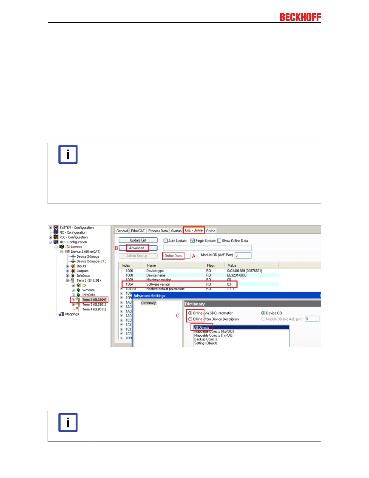
Appendix
EK110x, EK15xx76 Version: 3.6
KK - week of production (CW, calendar week)
YY - year of production
FF - firmware version
HH - hardware version
Example with ser. no.: 12 10 03 02:
12 - week of production 12
10 - year of production 2010
03 - firmware version 03
02 - hardware version 02
Determining the version via the System Manager
The TwinCAT System Manager shows the version of the controller firmware if the master can access the
slave online. Click on the E-Bus Terminal whose controller firmware you want to check (in the example
terminal 2 (EL3204)) and select the tab CoE Online (CAN over EtherCAT).
Note
CoE Online and Offline CoE
Two CoE directories are available:
• online: This is offered in the EtherCAT slave by the controller, if the EtherCAT slave supports this. This CoE directory can only be displayed if a slave is connected and operational.
• offline: The EtherCAT Slave Information ESI/XML may contain the default content of the
CoE. This CoE directory can only be displayed if it is included in the ESI (e.g. "Beckhoff
EL5xxx.xml").
The Advanced button must be used for switching between the two views.
In Fig. Display of EL3204 firmware version the firmware version of the selected EL3204 is shown as 03 in
CoE entry 0x100A.
Fig.61: Display of EL3204 firmware version
In (A) TwinCAT 2.11 shows that the Online CoE directory is currently displayed. If this is not the case, the
Online directory can be loaded via the Online option in Advanced Settings (B) and double-clicking on
AllObjects.
7.4.3 Updating controller firmware *.efw
Note
CoE directory
The Online CoE directory is managed by the controller and stored in a dedicated EEPROM,
which is generally not changed during a firmware update.
Page 77

Appendix
EK110x, EK15xx 77Version: 3.6
Switch to the Online tab to update the controller firmware of a slave, see Fig. Firmware Update.
Fig.62: Firmware Update
Proceed as follows, unless instructed otherwise by Beckhoff support. Valid for TwinCAT2 and 3 as
EtherCAT master.
• Switch TwinCAT system to ConfigMode/FreeRun with cycle time >= 1 ms (default in ConfigMode is 4
ms). A FW-Update during real time operation is not recommended.
• Switch EtherCAT Master to PreOP
• Switch slave to INIT (A)
Page 78

Appendix
EK110x, EK15xx78 Version: 3.6
• Switch slave to BOOTSTRAP
• Check the current status (B, C)
• Download the new *efw file (wait until it ends). A pass word will not be neccessary usually.
• After the download switch to INIT, then PreOP
• Switch off the slave briefly (don't pull under voltage!)
• Check within CoE 0x100A, if the FW status was correctly overtaken.
7.4.4 FPGA firmware *.rbf
If an FPGA chip deals with the EtherCAT communication an update may be accomplished via an *.rbf file.
• Controller firmware for processing I/O signals
• FPGA firmware for EtherCAT communication (only for terminals with FPGA)
The firmware version number included in the terminal serial number contains both firmware components. If
one of these firmware components is modified this version number is updated.
Determining the version via the System Manager
The TwinCAT System Manager indicates the FPGA firmware version. Click on the Ethernet card of your
EtherCAT strand (Device 2 in the example) and select the Online tab.
The Reg:0002 column indicates the firmware version of the individual EtherCAT devices in hexadecimal and
decimal representation.
Page 79

Appendix
EK110x, EK15xx 79Version: 3.6
Fig.63: FPGA firmware version definition
If the column Reg:0002 is not displayed, right-click the table header and select Properties in the context
menu.
Fig.64: Context menu Properties
The Advanced Settings dialog appears where the columns to be displayed can be selected. Under
Diagnosis/Online View select the '0002 ETxxxx Build' check box in order to activate the FPGA firmware
version display.
Page 80

Appendix
EK110x, EK15xx80 Version: 3.6
Fig.65: Dialog Advanced Settings
Update
For updating the FPGA firmware
• of an EtherCAT coupler the coupler must have FPGA firmware version 11 or higher;
• of an E-Bus Terminal the terminal must have FPGA firmware version 10 or higher.
Older firmware versions can only be updated by the manufacturer!
Updating an EtherCAT device
The following sequence order have to be met if no other specifications are given (e.g. by the Beckhoff
support):
• Switch TwinCAT system to ConfigMode/FreeRun with cycle time >= 1ms (default in ConfigMode is
4ms). A FW-Update during real time operation is not recommended.
Page 81

Appendix
EK110x, EK15xx 81Version: 3.6
• In the TwinCAT System Manager select the terminal for which the FPGA firmware is to be updated (in
the example: Terminal 5: EL5001) and
click the Advanced Settings button in the EtherCAT tab:
• The Advanced Settings dialog appears. Under ESC Access/E²PROM/FPGA click on Write FPGA
button:
Page 82

Appendix
EK110x, EK15xx82 Version: 3.6
• Select the file (*.rbf) with the new FPGA firmware, and transfer it to the EtherCAT device:
• Wait until download ends
• Switch slave current less for a short time (don't pull under voltage!). In order to activate the new FPGA
firmware a restart (switching the power supply off and on again) of the EtherCAT device is required.
• Check the new FPGA status
Attention
Risk of damage to the device!
A download of firmware to an EtherCAT device must not be interrupted in any case! If you
interrupt this process by switching off power supply or disconnecting the Ethernet link, the
EtherCAT device can only be recommissioned by the manufacturer!
7.4.5 Simultaneous updating of several EtherCAT devices
The firmware and ESI descriptions of several devices can be updated simultaneously, provided the devices
have the same firmware file/ESI.
Fig.66: Multiple selection and firmware update
Select the required slaves and carry out the firmware update in BOOTSTRAP mode as described above.
Page 83

Appendix
EK110x, EK15xx 83Version: 3.6
7.5 Support and Service
Beckhoff and their partners around the world offer comprehensive support and service, making available fast
and competent assistance with all questions related to Beckhoff products and system solutions.
Beckhoff's branch offices and representatives
Please contact your Beckhoff branch office or representative for local support and service on Beckhoff
products!
The addresses of Beckhoff's branch offices and representatives round the world can be found on her internet
pages:
http://www.beckhoff.com
You will also find further documentation for Beckhoff components there.
Beckhoff Headquarters
Beckhoff Automation GmbH & Co. KG
Huelshorstweg 20
33415 Verl
Germany
Phone: +49(0)5246/963-0
Fax: +49(0)5246/963-198
e-mail: info@beckhoff.com
Beckhoff Support
Support offers you comprehensive technical assistance, helping you not only with the application of
individual Beckhoff products, but also with other, wide-ranging services:
• support
• design, programming and commissioning of complex automation systems
• and extensive training program for Beckhoff system components
Hotline: +49(0)5246/963-157
Fax: +49(0)5246/963-9157
e-mail: support@beckhoff.com
Beckhoff Service
The Beckhoff Service Center supports you in all matters of after-sales service:
• on-site service
• repair service
• spare parts service
• hotline service
Hotline: +49(0)5246/963-460
Fax: +49(0)5246/963-479
e-mail: service@beckhoff.com
Page 84

List of illustrations
EK110x, EK15xx84 Version: 3.6
List of illustrations
Fig. 1 EL5021 EL terminal, standard IP20 IO device with batch number and revision ID (since
2014/01)....................................................................................................................................... 10
Fig. 2 EK1100 EtherCAT coupler, standard IP20 IO device with batch number ................................... 10
Fig. 3 CU2016 switch with batch number .............................................................................................. 11
Fig. 4 EL3202-0020 with batch numbers 26131006 and unique ID-number 204418 ............................ 11
Fig. 5 EP1258-00001 IP67 EtherCAT Box with batch number 22090101 and unique serial number
158102......................................................................................................................................... 11
Fig. 6 EP1908-0002 IP67 EtherCAT Safety Box with batch number 071201FF and unique serial
number 00346070........................................................................................................................ 11
Fig. 7 EL2904 IP20 safety terminal with batch number/date code 50110302 and unique serial num-
ber 00331701............................................................................................................................... 12
Fig. 8 ELM3604-0002 terminal with ID number (QR code) 100001051 and unique serial number
44160201..................................................................................................................................... 12
Fig. 9 EtherCAT coupler communication diagram ................................................................................. 13
Fig. 10 Identification of FHC port at EK1122-0080 and EK1101-0080 .................................................... 20
Fig. 11 Recommended combination of Ethernet ports ............................................................................ 20
Fig. 12 Configuration of a Fast Hot Connect group ................................................................................. 21
Fig. 13 Marking in the TwinCAT System Manager .................................................................................. 21
Fig. 14 DC master setting ........................................................................................................................ 22
Fig. 15 Example: EK1100 / EK1100-0008 EtherCAT coupler with 3 ports ............................................. 31
Fig. 16 Internal and external port assignment for Bus Coupler EK1100 and EK1100-0008 ................... 32
Fig. 17 States of the EtherCAT State Machine........................................................................................ 33
Fig. 18 DC tab for indicating the Distributed Clocks function................................................................... 34
Fig. 19 Advanced Distributed Clocks settings in the EtherCAT master................................................... 35
Fig. 20 TwinCAT setting for using this component as reference clock ................................................... 36
Fig. 21 Spring contacts of the Beckhoff I/O components......................................................................... 37
Fig. 22 Attaching on mounting rail ........................................................................................................... 38
Fig. 23 Disassembling of terminal............................................................................................................ 39
Fig. 24 Power contact on left side............................................................................................................ 40
Fig. 25 Recommended distances for standard installation position ........................................................ 42
Fig. 26 Other installation positions .......................................................................................................... 43
Fig. 27 Standard wiring............................................................................................................................ 44
Fig. 28 Pluggable wiring .......................................................................................................................... 44
Fig. 29 High Density Terminals................................................................................................................ 44
Fig. 30 Connecting a cable on a terminal point ....................................................................................... 45
Fig. 31 System manager current calculation .......................................................................................... 47
Fig. 32 ZK1090-3131-0xxx ...................................................................................................................... 47
Fig. 33 X1 and X2 of EK1100-0008 ......................................................................................................... 49
Fig. 34 EtherCAT Box with M8 connectors.............................................................................................. 49
Fig. 35 Potential diagram EKxxxx............................................................................................................ 50
Fig. 36 GND concept EKxxxx .................................................................................................................. 51
Fig. 37 Correct configuration ................................................................................................................... 52
Fig. 38 Incorrect configuration ................................................................................................................. 52
Fig. 39 EK1501 ....................................................................................................................................... 56
Fig. 40 EK1541 ....................................................................................................................................... 59
Fig. 41 Latching lug with release catch on the POF duplex plug............................................................. 60
Page 85

List of illustrations
EK110x, EK15xx 85Version: 3.6
Fig. 42 Duplex connector set ZS1090-0008 ........................................................................................... 62
Fig. 43 POF cable stripped over the same length ................................................................................... 62
Fig. 44 Cable inserted in the connector ................................................................................................... 63
Fig. 45 Closed connector......................................................................................................................... 63
Fig. 46 Correctly connected optical channels ......................................................................................... 63
Fig. 47 Sanding gauge with protruding fiber ends ................................................................................... 64
Fig. 48 Polishing in the form of a figure of 8 ........................................................................................... 64
Fig. 49 Fine-polished fibers in the connector........................................................................................... 65
Fig. 50 Diagnostic LEDs EK1100, EK1100-0008 .................................................................................... 66
Fig. 51 Diagnostic LEDs EK1101-xxxx .................................................................................................... 67
Fig. 52 Diagnostic LEDs for Bus Coupler EK1501 .................................................................................. 68
Fig. 53 Diagnostic LEDs for Bus Coupler EK1501-0010 ......................................................................... 69
Fig. 54 Diagnostic LEDs Bus Coupler EK1541........................................................................................ 70
Fig. 55 Device identifier consisting of name EL3204-0000 and revision -0016 ...................................... 73
Fig. 56 Scan the subordinate field by right-clicking on the EtherCAT device in Config/FreeRun mode . 73
Fig. 57 Configuration is identical ............................................................................................................. 74
Fig. 58 Change dialog ............................................................................................................................. 74
Fig. 59 EEPROM Update ........................................................................................................................ 75
Fig. 60 Selecting the new ESI.................................................................................................................. 75
Fig. 61 Display of EL3204 firmware version ............................................................................................ 76
Fig. 62 Firmware Update ......................................................................................................................... 77
Fig. 63 FPGA firmware version definition ............................................................................................... 79
Fig. 64 Context menu Properties ............................................................................................................ 79
Fig. 65 Dialog Advanced Settings ........................................................................................................... 80
Fig. 66 Multiple selection and firmware update ...................................................................................... 82
 Loading...