

Page 1

Documentation | EN
EK1300
EtherCAT P Coupler
2021-03-01 | Version: 1.1
Page 2

Page 3

Table of contents
Table of contents
1 Foreword ....................................................................................................................................................5
1.1 Notes on the documentation..............................................................................................................5
1.2 Safety instructions .............................................................................................................................6
1.3 Documentation issue status ..............................................................................................................7
1.4 Version identification of EtherCAT devices .......................................................................................7
1.4.1 Beckhoff Identification Code (BIC)................................................................................... 11
2 Product overview.....................................................................................................................................13
2.1 EK1300 - Introduction......................................................................................................................13
2.2 EtherCATP .....................................................................................................................................13
2.3 EK1300 - Technical data .................................................................................................................14
3 Basics communication ...........................................................................................................................15
3.1 System properties............................................................................................................................15
3.2 EtherCAT basics..............................................................................................................................18
3.3 EtherCAT State Machine.................................................................................................................18
3.4 CoE - Interface: notes......................................................................................................................19
3.5 Distributed Clock .............................................................................................................................19
3.6 EtherCAT P introduction..................................................................................................................19
4 Mounting and wiring................................................................................................................................23
4.1 Installation on mounting rails ...........................................................................................................23
4.2 Installation instructions for enhanced mechanical load capacity .....................................................25
4.3 Installation positions ........................................................................................................................26
4.4 Connection system ..........................................................................................................................28
4.5 Connection EK1300.........................................................................................................................31
4.6 EtherCAT P connection ...................................................................................................................31
4.7 Nut torque for connectors ................................................................................................................33
4.8 Cabling ............................................................................................................................................33
4.9 EtherCAT P cable conductor losses M8..........................................................................................37
5 Commissioning........................................................................................................................................38
5.1 EK1300 - Configuration by means of the TwinCAT System Manager.............................................38
6 Error handling and diagnostics..............................................................................................................46
6.1 Diagnostic LED................................................................................................................................46
7 Appendix ..................................................................................................................................................48
7.1 EtherCAT AL Status Codes.............................................................................................................48
7.2 Firmware compatibility.....................................................................................................................48
7.3 Support and Service ........................................................................................................................48
EK1300 3Version: 1.1
Page 4

Table of contents
EK13004 Version: 1.1
Page 5

Foreword
1 Foreword
1.1 Notes on the documentation
Intended audience
This description is only intended for the use of trained specialists in control and automation engineering who
are familiar with the applicable national standards.
It is essential that the documentation and the following notes and explanations are followed when installing
and commissioning these components.
It is the duty of the technical personnel to use the documentation published at the respective time of each
installation and commissioning.
The responsible staff must ensure that the application or use of the products described satisfy all the
requirements for safety, including all the relevant laws, regulations, guidelines and standards.
Disclaimer
The documentation has been prepared with care. The products described are, however, constantly under
development.
We reserve the right to revise and change the documentation at any time and without prior announcement.
No claims for the modification of products that have already been supplied may be made on the basis of the
data, diagrams and descriptions in this documentation.
Trademarks
Beckhoff®, TwinCAT®, EtherCAT®, EtherCATG®, EtherCATG10®, EtherCATP®, SafetyoverEtherCAT®,
TwinSAFE®, XFC®, XTS® and XPlanar® are registered trademarks of and licensed by Beckhoff Automation
GmbH. Other designations used in this publication may be trademarks whose use by third parties for their
own purposes could violate the rights of the owners.
Patent Pending
The EtherCAT Technology is covered, including but not limited to the following patent applications and
patents: EP1590927, EP1789857, EP1456722, EP2137893, DE102015105702 with corresponding
applications or registrations in various other countries.
EtherCAT® is registered trademark and patented technology, licensed by Beckhoff Automation GmbH,
Germany.
Copyright
© Beckhoff Automation GmbH & Co. KG, Germany.
The reproduction, distribution and utilization of this document as well as the communication of its contents to
others without express authorization are prohibited.
Offenders will be held liable for the payment of damages. All rights reserved in the event of the grant of a
patent, utility model or design.
EK1300 5Version: 1.1
Page 6
Foreword
1.2 Safety instructions
Safety regulations
Please note the following safety instructions and explanations!
Product-specific safety instructions can be found on following pages or in the areas mounting, wiring,
commissioning etc.
Exclusion of liability
All the components are supplied in particular hardware and software configurations appropriate for the
application. Modifications to hardware or software configurations other than those described in the
documentation are not permitted, and nullify the liability of Beckhoff Automation GmbH & Co. KG.
Personnel qualification
This description is only intended for trained specialists in control, automation and drive engineering who are
familiar with the applicable national standards.
Description of instructions
In this documentation the following instructions are used.
These instructions must be read carefully and followed without fail!
DANGER
Serious risk of injury!
Failure to follow this safety instruction directly endangers the life and health of persons.
WARNING
Risk of injury!
Failure to follow this safety instruction endangers the life and health of persons.
CAUTION
Personal injuries!
Failure to follow this safety instruction can lead to injuries to persons.
NOTE
Damage to environment/equipment or data loss
Failure to follow this instruction can lead to environmental damage, equipment damage or data loss.
Tip or pointer
This symbol indicates information that contributes to better understanding.
EK13006 Version: 1.1
Page 7

Foreword
1.3 Documentation issue status
Version Modifications
1.1 • Addenda within chapter „Version identification of EtherCAT devices“ of chapter
„Beckhoff Identification Code (BIC)“
• Addenda within chapter „Support and Service“ (appendix)
• Chapter „Safety instructions“ updated
• Chapter „EtherCAT P cable conductor losses M8“ updated
1.0 • Corrections
• 1st public issue
0.1 • First preliminary version
1.4 Version identification of EtherCAT devices
Designation
A Beckhoff EtherCAT device has a 14-digit designation, made up of
• family key
• type
• version
• revision
Example Family Type Version Revision
EL3314-0000-0016 EL terminal
(12 mm, nonpluggable connection
level)
ES3602-0010-0017 ES terminal
(12 mm, pluggable
connection level)
CU2008-0000-0000 CU device 2008 (8-port fast ethernet switch) 0000 (basic type) 0000
Notes
• The elements mentioned above result in the technical designation. EL3314-0000-0016 is used in the
example below.
• EL3314-0000 is the order identifier, in the case of “-0000” usually abbreviated to EL3314. “-0016” is the
EtherCAT revision.
• The order identifier is made up of
- family key (EL, EP, CU, ES, KL, CX, etc.)
- type (3314)
- version (-0000)
• The revision -0016 shows the technical progress, such as the extension of features with regard to the
EtherCAT communication, and is managed by Beckhoff.
In principle, a device with a higher revision can replace a device with a lower revision, unless specified
otherwise, e.g. in the documentation.
Associated and synonymous with each revision there is usually a description (ESI, EtherCAT Slave
Information) in the form of an XML file, which is available for download from the Beckhoff web site.
From 2014/01 the revision is shown on the outside of the IP20 terminals, see Fig. “EL5021 EL terminal,
standard IP20 IO device with batch number and revision ID (since 2014/01)”.
• The type, version and revision are read as decimal numbers, even if they are technically saved in
hexadecimal.
3314 (4-channel thermocouple
terminal)
3602 (2-channel voltage
measurement)
0000 (basic type) 0016
0010 (highprecision version)
0017
EK1300 7Version: 1.1
Page 8

Foreword
Identification number
Beckhoff EtherCAT devices from the different lines have different kinds of identification numbers:
Production lot/batch number/serial number/date code/D number
The serial number for Beckhoff IO devices is usually the 8-digit number printed on the device or on a sticker.
The serial number indicates the configuration in delivery state and therefore refers to a whole production
batch, without distinguishing the individual modules of a batch.
Structure of the serial number: KKYYFFHH
KK - week of production (CW, calendar week)
YY - year of production
FF - firmware version
HH - hardware version
Example with
Ser. no.: 12063A02: 12 - production week 12 06 - production year 2006 3A - firmware version 3A 02 hardware version 02
Exceptions can occur in the IP67 area, where the following syntax can be used (see respective device
documentation):
Syntax: D ww yy x y z u
D - prefix designation
ww - calendar week
yy - year
x - firmware version of the bus PCB
y - hardware version of the bus PCB
z - firmware version of the I/O PCB
u - hardware version of the I/O PCB
Example: D.22081501 calendar week 22 of the year 2008 firmware version of bus PCB: 1 hardware version
of bus PCB: 5 firmware version of I/O PCB: 0 (no firmware necessary for this PCB) hardware version of I/O
PCB: 1
Unique serial number/ID, ID number
In addition, in some series each individual module has its own unique serial number.
See also the further documentation in the area
• IP67: EtherCAT Box
• Safety: TwinSafe
• Terminals with factory calibration certificate and other measuring terminals
Examples of markings
Fig.1: EL5021 EL terminal, standard IP20 IO device with serial/ batch number and revision ID (since
2014/01)
EK13008 Version: 1.1
Page 9
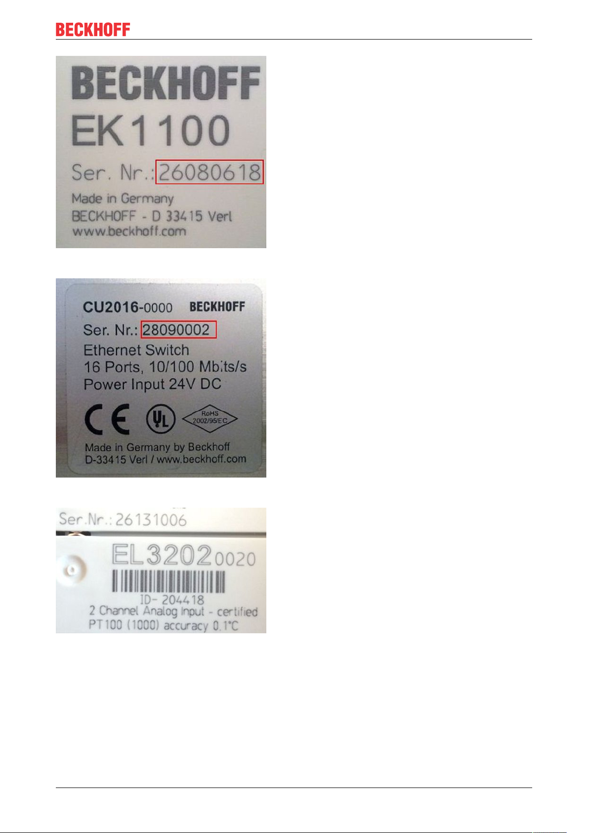
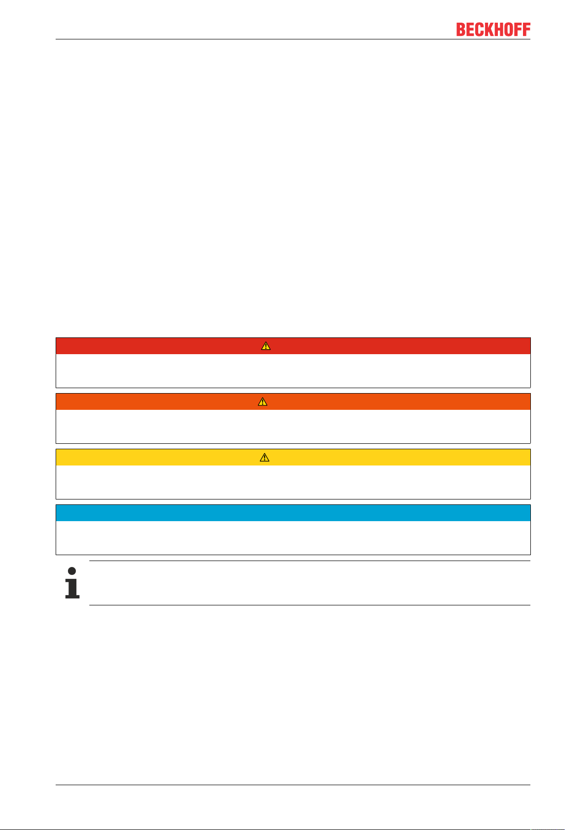
Fig.2: EK1100 EtherCAT coupler, standard IP20 IO device with serial/ batch number
Foreword
Fig.3: CU2016 switch with serial/ batch number
Fig.4: EL3202-0020 with serial/ batch number 26131006 and unique ID-number 204418
EK1300 9Version: 1.1
Page 10
Foreword
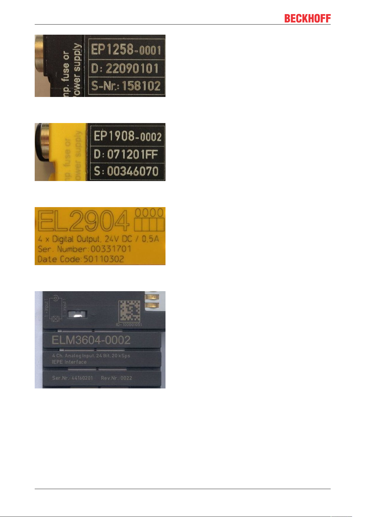
Fig.5: EP1258-00001 IP67 EtherCAT Box with batch number/ date code 22090101 and unique serial
number 158102
Fig.6: EP1908-0002 IP67 EtherCAT Safety Box with batch number/ date code 071201FF and unique serial
number 00346070
Fig.7: EL2904 IP20 safety terminal with batch number/ date code 50110302 and unique serial number
00331701
Fig.8: ELM3604-0002 terminal with unique ID number (QR code) 100001051 and serial/ batch number
44160201
EK130010 Version: 1.1
Page 11
Foreword
1.4.1 Beckhoff Identification Code (BIC)
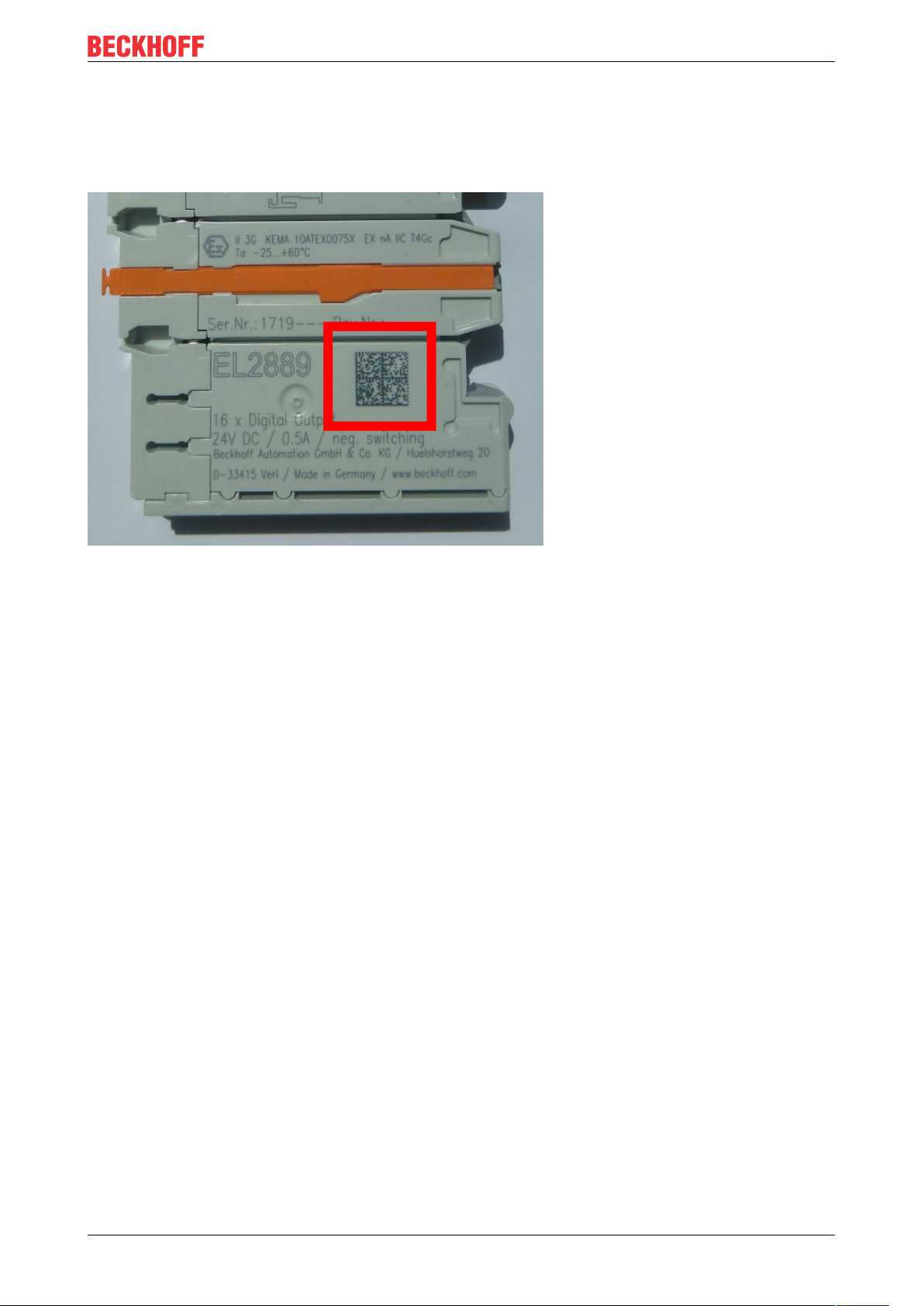
The Beckhoff Identification Code (BIC) is increasingly being applied to Beckhoff products to uniquely identify
the product. The BIC is represented as a Data Matrix Code (DMC, code scheme ECC200), the content is
based on the ANSI standard MH10.8.2-2016.
Fig.9: BIC as data matrix code (DMC, code scheme ECC200)
The BIC will be introduced step by step across all product groups.
Depending on the product, it can be found in the following places:
• on the packaging unit
• directly on the product (if space suffices)
• on the packaging unit and the product
The BIC is machine-readable and contains information that can also be used by the customer for handling
and product management.
Each piece of information can be uniquely identified using the so-called data identifier
(ANSIMH10.8.2-2016). The data identifier is followed by a character string. Both together have a maximum
length according to the table below. If the information is shorter, spaces are added to it. The data under
positions 1 to 4 are always available.
The following information is contained:
EK1300 11Version: 1.1
Page 12

Foreword
Item
Type of
no.
information
1 Beckhoff order
number
2 Beckhoff Traceability
Number (BTN)
3 Article description Beckhoff article
4 Quantity Quantity in packaging
5 Batch number Optional: Year and week
6 ID/serial number Optional: Present-day
7 Variant number Optional: Product variant
...
Explanation Data
Beckhoff order number 1P 8 1P072222
Unique serial number,
see note below
description, e.g.
EL1008
unit, e.g. 1, 10, etc.
of production
serial number system,
e.g. with safety products
or calibrated terminals
number on the basis of
standard products
Number of digits
identifier
S 12 SBTNk4p562d7
1K 32 1KEL1809
Q 6 Q1
2P 14 2P401503180016
51S 12 51S678294104
30P 32 30PF971, 2*K183
incl. data identifier
Example
Further types of information and data identifiers are used by Beckhoff and serve internal processes.
Structure of the BIC
Example of composite information from item 1 to 4 and 6. The data identifiers are marked in red for better
display:
BTN
An important component of the BIC is the Beckhoff Traceability Number (BTN, item no.2). The BTN is a
unique serial number consisting of eight characters that will replace all other serial number systems at
Beckhoff in the long term (e.g. batch designations on IO components, previous serial number range for
safety products, etc.). The BTN will also be introduced step by step, so it may happen that the BTN is not yet
coded in the BIC.
NOTE
This information has been carefully prepared. However, the procedure described is constantly being further
developed. We reserve the right to revise and change procedures and documentation at any time and without prior notice. No claims for changes can be made from the information, illustrations and descriptions in
this information.
EK130012 Version: 1.1
Page 13
2 Product overview
2.1 EK1300 - Introduction
Product overview
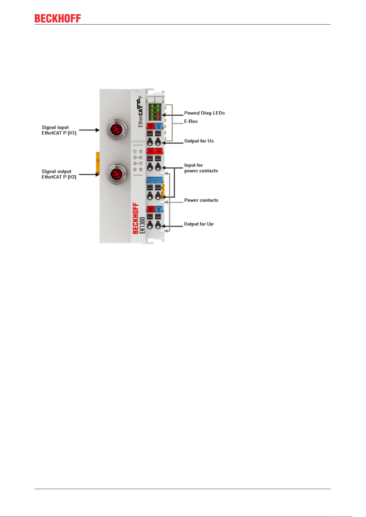
EtherCAT coupler EK1300
The EK1300 coupler integrates EtherCAT Terminals (ELxxxx) in the EtherCAT P network. The upper
EtherCAT P interface is used to connect the coupler to the network, the lower EtherCAT-P-coded M8 socket
is used for optional continuation of the EtherCAT P topology. Since EtherCAT P integrates the power supply
and the communication on a single line, an additional power supply for the coupler via the terminal points is
no longer required. Depending on the application, the system and sensor supply US or the peripheral voltage
for actuators UP can be bridged to the power contacts. In addition to the Run LED and the link and activity
status, status LEDs indicate the state of the US and UP voltages, as well as overload and short-circuit events.
2.2 EtherCATP
EtherCATP combines communication and power in a single 4-wire standard Ethernet cable. The 24VDC
supply of the EtherCATP slaves and the connected sensors and actors is integrated within this bus system:
US (system- and Sensor supply) and UP (peripheral voltage for actors) are electrical isolated with 3A current
available for the connected components. All the benefits of EtherCAT, such as freedom in topology design,
high speed, optimum bandwidth utilization, telegram processing on-the-fly, highly precise synchronization,
extensive diagnostics functionality, etc. are all retained while integrating the voltages.
With EtherCATP technology, the currents are coupled directly into the wires of the 100 Mbit line, enabling
the realization of a highly cost-effective and compact connection. In order to rule out the possibility of
incorrect connections to standard EtherCAT slaves and, thus possible defects, a new plug family has been
specially developed for EtherCATP. The plug family covers all applications from the 24 V I/O level up to
drives with 400 V AC or 600 V DC and a current of up to 64 A.
EtherCATP offers extensive savings potential:
• elimination of separate supply cables
• low wiring effort and significant time savings
• sources of error are reduced
EK1300 13Version: 1.1
Page 14

Product overview
• minimization of installation space for drag-chains and control cabinets
• smaller and tidier cable trays
• smaller sensors and actuators through the elimination of separate supply cables
As is typical with EtherCAT, the user benefits from the wide choice in topology and can combine line, star
and tree architectures with one another in order to achieve the least expensive and best possible system
layouts. Unlike the traditional Power over Ethernet (PoE), devices can also be cascaded using EtherCATP
and supplied with power from one power supply unit.
When designing a machine, the individual consumers, cable lengths and cable types are configured with tool
assistance and this information is used to create the optimum layout of the EtherCATP network. Since it is
known what sensors and actuators will be connected and which ones will be operated simultaneously, the
power consumption can be accounted for accordingly. For example, if two actuators never switch
simultaneously from a logical point of view, they also never need the full load simultaneously. The result is
further savings potential in terms of the required supplies and power supply units.
Also see about this
2 EtherCAT P introduction [}19]
2.3 EK1300 - Technical data
Technical data EK1300
Task within the EtherCAT system coupling of EtherCAT Terminals (ELxxxx) to
100BASE‑TX EtherCAT P networks
Data transfer medium EtherCAT P cable, shielded, to 100BASE‑TX
EtherCAT P networks
Bus interface 2 x M8 socket, shielded, screw type,
EtherCAT‑P‑coded
Power supply from EtherCAT P (24 V DC for US and UP)
Total current from EtherCAT P, max. 3 A per US and U
Current consumption from U
Current consumption from U
S
P
40 mA + (∑ E‑bus current/4)
4 mA typ.
P
Current supply E-bus 2000 mA
Current rating per port max. 3 A per US and U
P
Electrical isolation 500 V (power contact/supply voltage/Ethernet)
Dimensions (W x H x D) approx. 44mm x 100mm x 68mm
Weight approx. 175g
Permissible ambient temperature range during
0°C ... +55°C
operation
Permissible ambient temperature range during
‑25°C ... + 85°C
storage
Permissible relative humidity 95%, no condensation
Mounting on 35 mm mounting rail conforms to EN 60715
Vibration/shock resistance conforms to EN 60068‑2‑6/EN 60068‑2‑27,
see also Installation instructions [}25] for terminals
with increased mechanical load capacity
EMC immunity/emission conforms to EN 61000‑6‑2 / EN 61000‑6‑4
Protection class IP20
Installation position variable
Approval CE
EK130014 Version: 1.1
Page 15
Basics communication
3 Basics communication
3.1 System properties
Protocol
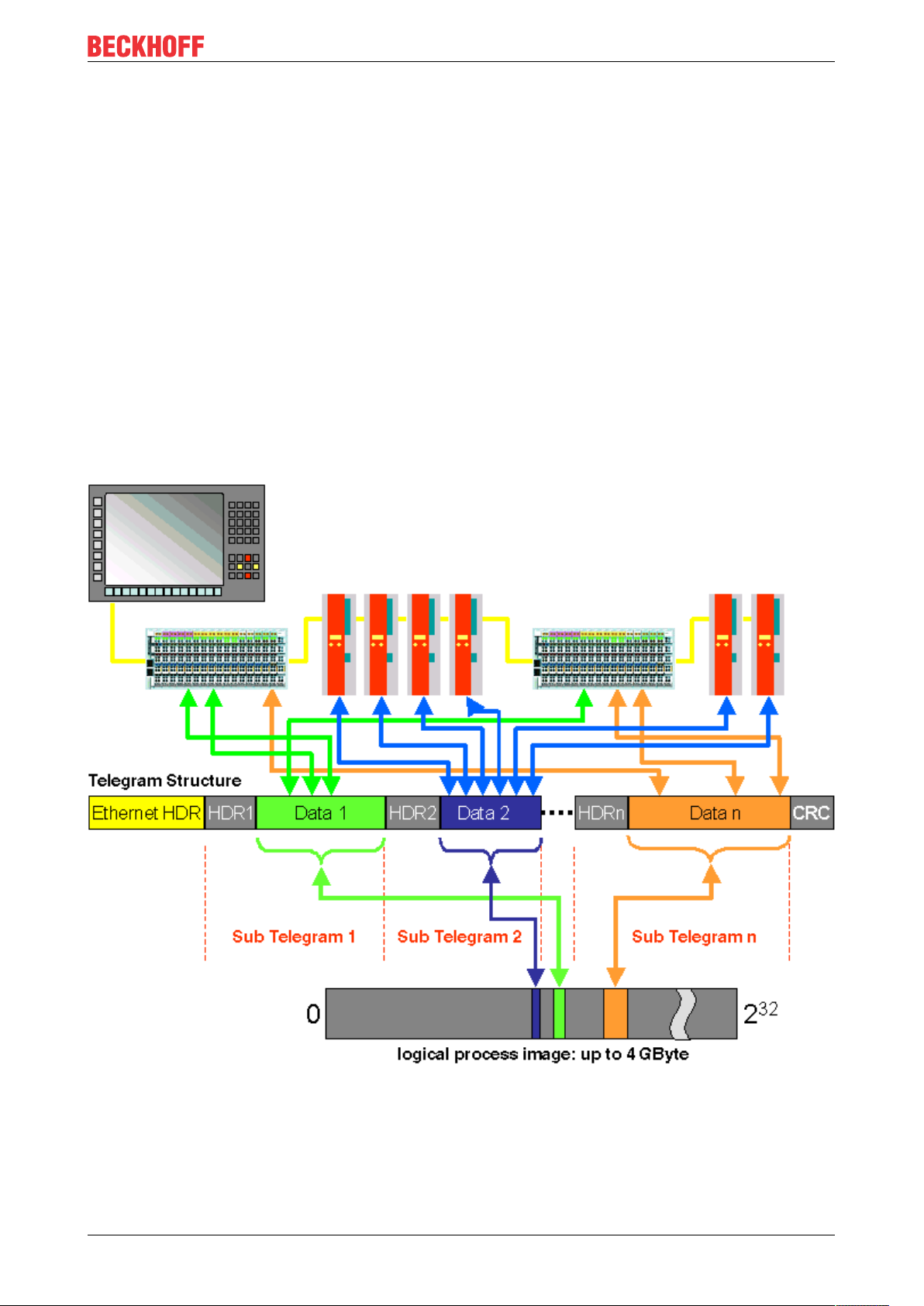
The EtherCAT protocol is optimized for process data and is transported directly within the Ethernet frame
thanks to a special Ether-type. It may consist of several sub-telegrams, each serving a particular memory
area of the logical process images that can be up to 4 gigabytes in size. The data sequence is independent
of the physical order of the Ethernet terminals in the network; addressing can be in any order. Broadcast,
Multicast and communication between slaves are possible. Transfer directly in the Ethernet frame is used in
cases where EtherCAT components are operated in the same subnet as the control computer.
However, EtherCAT applications are not limited to a subnet: EtherCAT UDP packs the EtherCAT protocol
into UDP/IP datagrams. This enables any control with Ethernet protocol stack to address EtherCAT systems.
Even communication across routers into other subnets is possible. In this variant, system performance
obviously depends on the real-time characteristics of the control and its Ethernet protocol implementation.
The response times of the EtherCAT network itself are hardly restricted at all: the UDP datagram only has to
be unpacked in the first station.
Fig.10: EtherCAT Telegram Structure
Protocol structure: The process image allocation is freely configurable. Data are copied directly in the I/O
terminal to the desired location within the process image: no additional mapping is required. The available
logical address space is with very large (4 GB).
EK1300 15Version: 1.1
Page 16
Basics communication
Topology
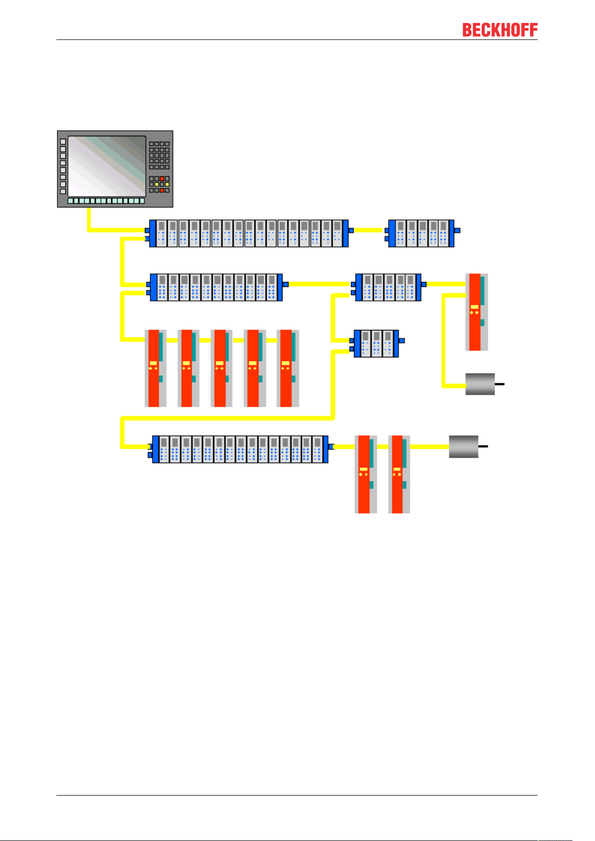
Line, tree or star: EtherCAT supports almost any topology. The bus or line structure known from the
fieldbuses thus also becomes available for Ethernet. Particularly useful for system wiring is the combination
of line and junctions or stubs. The required interfaces exist on the couplers; no additional switches are
required. Naturally, the classic switch-based Ethernet star topology can also be used.
Fig.11: EtherCAT Topology
Maximum wiring flexibility:
with or without switch, line or tree topologies, can be freely selected and combined.
Wiring flexibility is further maximized through the choice of different cables. Flexible and cost-effective
standard Ethernet patch cables transfer the signals in Ethernet mode (100Base-TX). The complete
bandwidth of the Ethernet network - such as different optical fibers and copper cables - can be used in
combination with switches or media converters.
Distributed Clocks
Accurate synchronization is particularly important in cases where spatially distributed processes require
simultaneous actions. This may be the case, for example, in applications where several servo axes carry out
coordinated movements simultaneously.
The most powerful approach for synchronization is the accurate alignment of distributed clocks, as described
in the new IEEE 1588 standard. In contrast to fully synchronous communication, where synchronization
quality suffers immediately in the event of a communication fault, distributed aligned clocks have a high
degree of tolerance vis-à-vis possible fault-related delays within the communication system.
EK130016 Version: 1.1
Page 17

Basics communication
With EtherCAT, the data exchange is fully based on a pure hardware machine. Since the communication
utilizes a logical (and thanks to full-duplex Fast Ethernet also physical) ring structure, the mother clock can
determine the run-time offset to the individual daughter clocks simply and accurately - and vice versa. The
distributed clocks are adjusted based on this value, which means that a very precise network-wide timebase
with a jitter of significantly less than 1 microsecond is available.
However, high-resolution distributed clocks are not only used for synchronization, but can also provide
accurate information about the local timing of the data acquisition. For example, controls frequently calculate
velocities from sequentially measured positions. Particularly with very short sampling times, even a small
temporal jitter in the displacement measurement leads to large step changes in velocity. With EtherCAT new,
extended data types are introduced as a logical extension (time stamp and oversampling data type). The
local time is linked to the measured value with a resolution of up to 10 ns, which is made possible by the
large bandwidth offered by Ethernet. The accuracy of a velocity calculation then no longer depends on the
jitter of the communication system. It is orders of magnitude better than that of measuring techniques based
on jitter-free communication.
Performance
EtherCAT reaches new dimensions in network performance. Protocol processing is purely hardware-based
through an FMMU chip in the terminal and DMA access to the network card of the master. It is thus
independent of protocol stack run-times, CPU performance and software implementation. The update time
for 1000 I/Os is only 30 µs - including terminal cycle time. Up to 1486 bytes of process data can be
exchanged with a single Ethernet frame - this is equivalent to almost 12000 digital inputs and outputs. The
transfer of this data quantity only takes 300 µs.
The communication with 100 servo axes only takes 100 µs. During this time, all axes are provided with set
values and control data and report their actual position and status. Distributed clocks enable the axes to be
synchronized with a deviation of significantly less than 1 microsecond.
The extremely high performance of the EtherCAT technology enables control concepts that could not be
realized with classic fieldbus systems. For example, the Ethernet system can now not only deal with velocity
control, but also with the current control of distributed drives. The tremendous bandwidth enables status
information to be transferred with each data item. With EtherCAT, a communication technology is available
that matches the superior computing power of modern Industrial PCs. The bus system is no longer the
bottleneck of the control concept. Distributed I/Os are recorded faster than is possible with most local I/O
interfaces. The EtherCAT technology principle is scalable and not bound to the baud rate of 100 Mbaud –
extension to Gbit Ethernet is possible.
Diagnostics
Experience with fieldbus systems shows that availability and commissioning times crucially depend on the
diagnostic capability. Only faults that are detected quickly and accurately and which can be precisely located
can be corrected quickly. Therefore, special attention was paid to exemplary diagnostic features during the
development of EtherCAT.
During commissioning, the actual configuration of the I/O terminals should be checked for consistency with
the specified configuration. The topology should also match the saved configuration. Due to the built-in
topology recognition down to the individual terminals, this verification can not only take place during system
start-up, automatic reading in of the network is also possible (configuration upload).
Bit faults during the transfer are reliably detected through evaluation of the CRC checksum: The 32 bit CRC
polynomial has a minimum hamming distance of 4. Apart from breaking point detection and localization, the
protocol, physical transfer behavior and topology of the EtherCAT system enable individual quality
monitoring of each individual transmission segment. The automatic evaluation of the associated error
counters enables precise localization of critical network sections. Gradual or changing sources of error such
as EMC influences, defective push-in connectors or cable damage are detected and located, even if they do
not yet overstrain the self-healing capacity of the network.
Integration of standard Bus Terminals from Beckhoff
In addition to the new Bus Terminals with E-Bus connection (ELxxxx), all Bus Terminals from the familiar
standard range with K-bus connection (KLxxxx) can be connected via the BK1120 or BK1250 Bus Coupler.
This ensures compatibility and continuity with the existing Beckhoff Bus Terminal systems. Existing
investments are protected.
EK1300 17Version: 1.1
Page 18
Basics communication
3.2 EtherCAT basics
Please refer to the EtherCAT System Documentation for the EtherCAT fieldbus basics.
3.3 EtherCAT State Machine
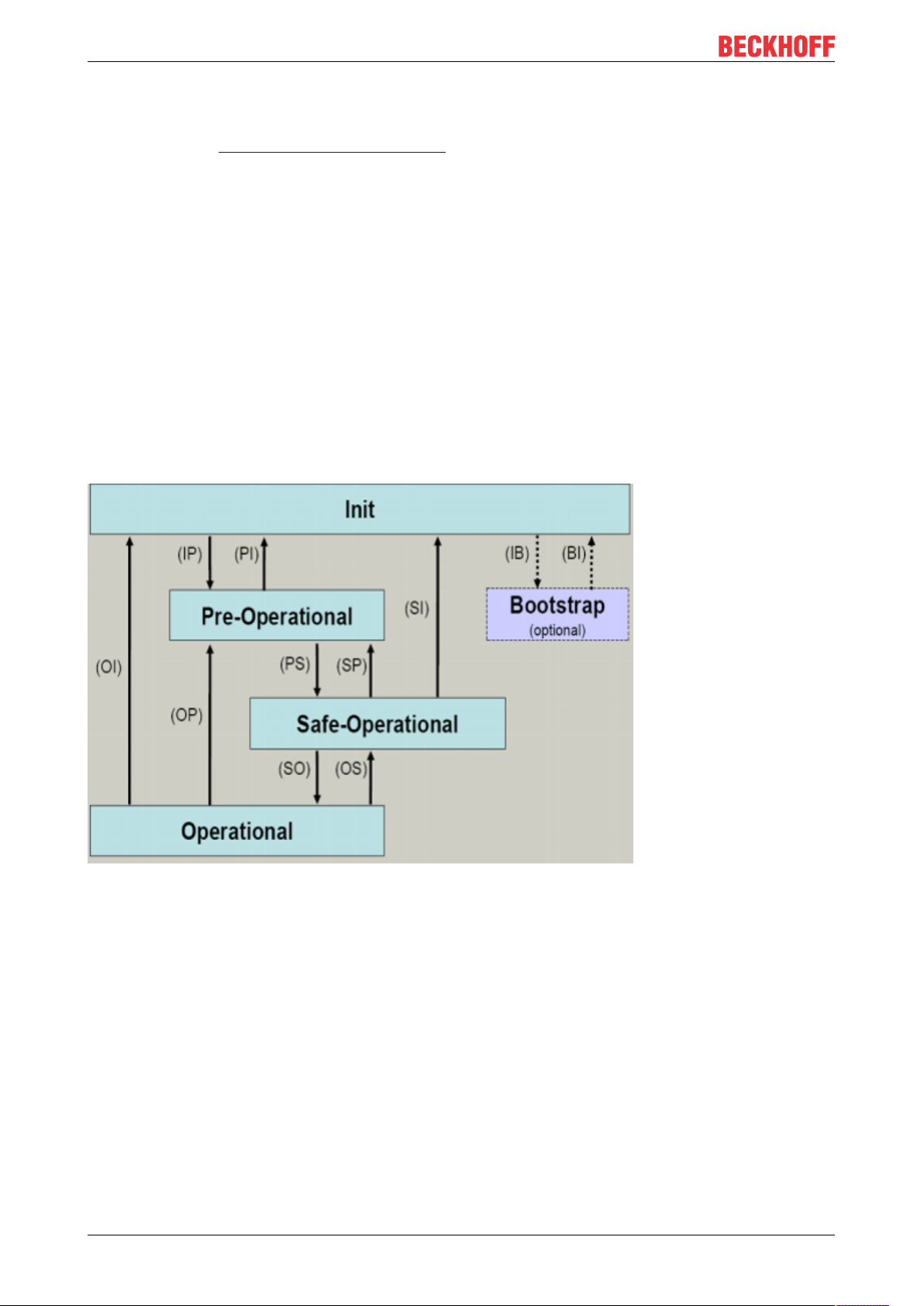
The state of the EtherCAT slave is controlled via the EtherCAT State Machine (ESM). Depending upon the
state, different functions are accessible or executable in the EtherCAT slave. Specific commands must be
sent by the EtherCAT master to the device in each state, particularly during the bootup of the slave.
A distinction is made between the following states:
• Init
• Pre-Operational
• Safe-Operational and
• Operational
• Boot
The regular state of each EtherCAT slave after bootup is the OP state.
Fig.12: States of the EtherCAT State Machine
Init
After switch-on the EtherCAT slave in the Init state. No mailbox or process data communication is possible.
The EtherCAT master initializes sync manager channels 0 and 1 for mailbox communication.
Pre-Operational (Pre-Op)
During the transition between Init and Pre-Op the EtherCAT slave checks whether the mailbox was initialized
correctly.
In Pre-Op state mailbox communication is possible, but not process data communication. The EtherCAT
master initializes the sync manager channels for process data (from sync manager channel 2), the FMMU
channels and, if the slave supports configurable mapping, PDO mapping or the sync manager PDO
assignment. In this state the settings for the process data transfer and perhaps terminal-specific parameters
that may differ from the default settings are also transferred.
EK130018 Version: 1.1
Page 19

Basics communication
Safe-Operational (Safe-Op)
During transition between Pre-Op and Safe-Op the EtherCAT slave checks whether the sync manager
channels for process data communication and, if required, the distributed clocks settings are correct. Before
it acknowledges the change of state, the EtherCAT slave copies current input data into the associated DPRAM areas of the EtherCAT slave controller (ECSC).
In Safe-Op state mailbox and process data communication is possible, although the slave keeps its outputs
in a safe state, while the input data are updated cyclically.
Outputs in SAFEOP state
The default set watchdog monitoring sets the outputs of the module in a safe state - depending on
the settings in SAFEOP and OP - e.g. in OFF state. If this is prevented by deactivation of the watchdog monitoring in the module, the outputs can be switched or set also in the SAFEOP state.
Operational (Op)
Before the EtherCAT master switches the EtherCAT slave from Safe-Op to Op it must transfer valid output
data.
In the Op state the slave copies the output data of the masters to its outputs. Process data and mailbox
communication is possible.
Boot
In the Boot state the slave firmware can be updated. The Boot state can only be reached via the Init state.
In the Boot state mailbox communication via the file access over EtherCAT (FoE) protocol is possible, but no
other mailbox communication and no process data communication.
3.4 CoE - Interface: notes
This device has no CoE.
Detailed information on the CoE interface can be found in the EtherCAT system documentation on the
Beckhoff website.
3.5 Distributed Clock
The distributed clock represents a local clock in the EtherCAT slave controller (ESC) with the following
characteristics:
• Unit 1 ns
• Zero point 1.1.2000 00:00
• Size 64 bit (sufficient for the next 584 years; however, some EtherCAT slaves only offer 32-bit support,
i.e. the variable overflows after approx. 4.2 seconds)
• The EtherCAT master automatically synchronizes the local clock with the master clock in the EtherCAT
bus with a precision of < 100 ns.
For detailed information please refer to the EtherCAT system description.
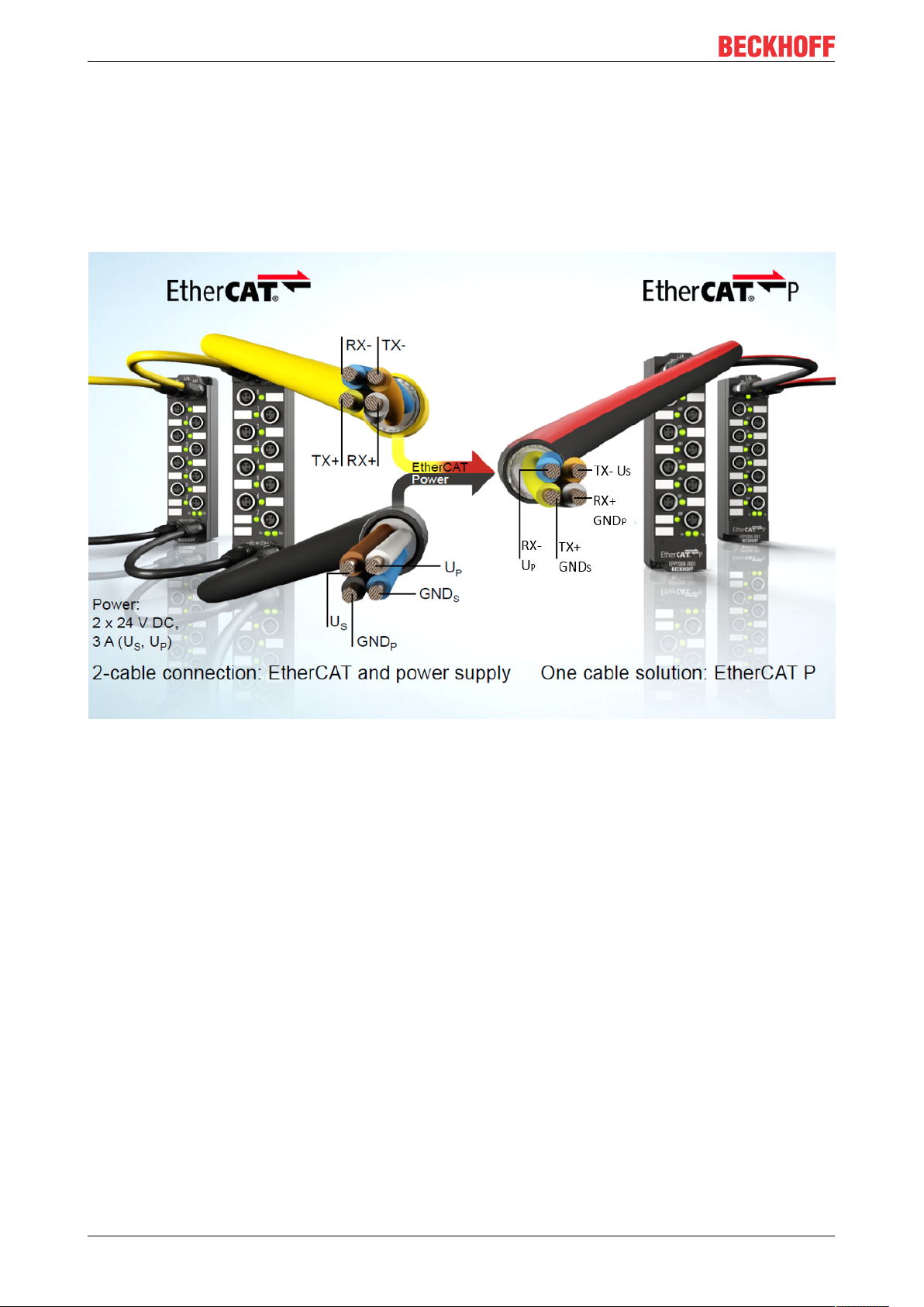
3.6 EtherCAT P introduction
One cable solution for the field level
With EtherCAT P, Beckhoff combines communication and power in a single 4-wire standard Ethernet cable.
The 24 V DC supply of the EtherCAT P slaves and of the connected sensors and actuators is integrated: US
(system and sensor supply) and UP (peripheral voltage for actuators) are electrically isolated from each
EK1300 19Version: 1.1
Page 20
Basics communication
other and can each supply a current of up to 3 A to the connected components. At the same time, all the
benefits of EtherCAT, such as: Cascadable in all topologies (star, line, tree), telegram processing on-the-fly,
high data transfer rate 100Mbit/s full duplex, optimum bandwidth utilization, highly precise synchronization,
extensive diagnostics functionality, etc., are all retained.
The currents of US and UP are coupled directly into the wires of the 100 Mbit/s line, enabling the realisation of
a highly cost-effective and compact connection. EtherCATP offers benefits both for connection of remote,
smaller I/O stations in the terminal box and for decentralised I/O components locally in the process. The
function principle of the one cable solution for the field is shown in the following figure.
Fig.13: From EtherCAT to EtherCATP
The mechanical EtherCATP coding (see figure below) was developed to prevent potential damage caused
by incorrect connection with standard EtherCAT modules. The connector face consists of a centrally located
T-piece and a nose and a triangle outside, also the 4 contacts are arranged symmetrically.
EK130020 Version: 1.1
Page 21
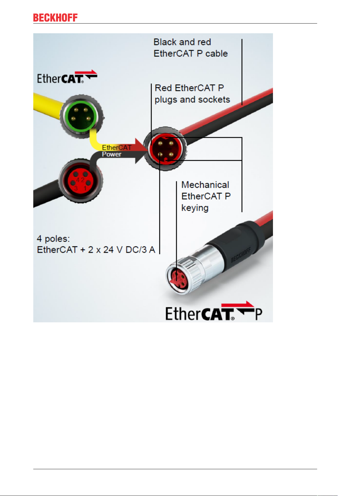
Basics communication
Fig.14: Connector face: EtherCAT, Power and EtherCAT P
System overview
The system overview (see following figure) shows the free choice of topology with IP 20 and IP 67 products.
Also the wide range of modules for different types of signals is significantly. EtherCATP can directly supply
the sensors/actuators. The sensors/actuators can be supplied directly with power via EtherCATP.
EK1300 21Version: 1.1
Page 22

Basics communication
Fig.15: EtherCAT P: System overview for IP 20 and IP 67
EK130022 Version: 1.1
Page 23

Mounting and wiring
4 Mounting and wiring
4.1 Installation on mounting rails
WARNING
Risk of electric shock and damage of device!
Bring the bus terminal system into a safe, powered down state before starting installation, disassembly or
wiring of the bus terminals!
Assembly
Fig.16: Attaching on mounting rail
The bus coupler and bus terminals are attached to commercially available 35mm mounting rails (DIN rails
according to EN60715) by applying slight pressure:
1. First attach the fieldbus coupler to the mounting rail.
2. The bus terminals are now attached on the right-hand side of the fieldbus coupler. Join the components with tongue and groove and push the terminals against the mounting rail, until the lock clicks
onto the mounting rail.
If the terminals are clipped onto the mounting rail first and then pushed together without tongue and
groove, the connection will not be operational! When correctly assembled, no significant gap should
be visible between the housings.
Fixing of mounting rails
The locking mechanism of the terminals and couplers extends to the profile of the mounting rail. At
the installation, the locking mechanism of the components must not come into conflict with the fixing
bolts of the mounting rail. To mount the mounting rails with a height of 7.5mm under the terminals
and couplers, you should use flat mounting connections (e.g. countersunk screws or blind rivets).
EK1300 23Version: 1.1
Page 24

Mounting and wiring
Disassembly
Fig.17: Disassembling of terminal
Each terminal is secured by a lock on the mounting rail, which must be released for disassembly:
1. Pull the terminal by its orange-colored lugs approximately 1cm away from the mounting rail. In doing
so for this terminal the mounting rail lock is released automatically and you can pull the terminal out of
the bus terminal block easily without excessive force.
2. Grasp the released terminal with thumb and index finger simultaneous at the upper and lower grooved
housing surfaces and pull the terminal out of the bus terminal block.
Connections within a bus terminal block
The electric connections between the Bus Coupler and the Bus Terminals are automatically realized by
joining the components:
• The six spring contacts of the K-Bus/E-Bus deal with the transfer of the data and the supply of the Bus
Terminal electronics.
• The power contacts deal with the supply for the field electronics and thus represent a supply rail within
the bus terminal block. The power contacts are supplied via terminals on the Bus Coupler (up to 24V)
or for higher voltages via power feed terminals.
Power Contacts
During the design of a bus terminal block, the pin assignment of the individual Bus Terminals must
be taken account of, since some types (e.g. analog Bus Terminals or digital 4-channel Bus Terminals) do not or not fully loop through the power contacts. Power Feed Terminals (KL91xx, KL92xx
or EL91xx, EL92xx) interrupt the power contacts and thus represent the start of a new supply rail.
PE power contact
The power contact labeled PE can be used as a protective earth. For safety reasons this contact mates first
when plugging together, and can ground short-circuit currents of up to 125A.
EK130024 Version: 1.1
Page 25

Fig.18: Power contact on left side
Mounting and wiring
NOTE
Possible damage of the device
Note that, for reasons of electromagnetic compatibility, the PE contacts are capacitatively coupled to the
mounting rail. This may lead to incorrect results during insulation testing or to damage on the terminal (e.g.
disruptive discharge to the PE line during insulation testing of a consumer with a nominal voltage of 230V).
For insulation testing, disconnect the PE supply line at the Bus Coupler or the Power Feed Terminal! In order to decouple further feed points for testing, these Power Feed Terminals can be released and pulled at
least 10mm from the group of terminals.
WARNING
Risk of electric shock!
The PE power contact must not be used for other potentials!
4.2 Installation instructions for enhanced mechanical load capacity
WARNING
Risk of injury through electric shock and damage to the device!
Bring the Bus Terminal system into a safe, de-energized state before starting mounting, disassembly or
wiring of the Bus Terminals!
Additional checks
The terminals have undergone the following additional tests:
Verification Explanation
Vibration 10 frequency runs in 3 axes
6 Hz < f < 60 Hz displacement 0.35 mm, constant amplitude
60.1Hz<f<500Hz acceleration 5g, constant amplitude
Shocks 1000 shocks in each direction, in 3 axes
25 g, 6 ms
EK1300 25Version: 1.1
Page 26

Mounting and wiring
Additional installation instructions
For terminals with enhanced mechanical load capacity, the following additional installation instructions apply:
• The enhanced mechanical load capacity is valid for all permissible installation positions
• Use a mounting rail according to EN 60715 TH35-15
• Fix the terminal segment on both sides of the mounting rail with a mechanical fixture, e.g. an earth
terminal or reinforced end clamp
• The maximum total extension of the terminal segment (without coupler) is:
64 terminals (12mm mounting with) or 32 terminals (24mm mounting with)
• Avoid deformation, twisting, crushing and bending of the mounting rail during edging and installation of
the rail
• The mounting points of the mounting rail must be set at 5 cm intervals
• Use countersunk head screws to fasten the mounting rail
• The free length between the strain relief and the wire connection should be kept as short as possible. A
distance of approx. 10cm should be maintained to the cable duct.
4.3 Installation positions
NOTE
Constraints regarding installation position and operating temperature range
Please refer to the technical data for a terminal to ascertain whether any restrictions regarding the installation position and/or the operating temperature range have been specified. When installing high power dissipation terminals ensure that an adequate spacing is maintained between other components above and below the terminal in order to guarantee adequate ventilation!
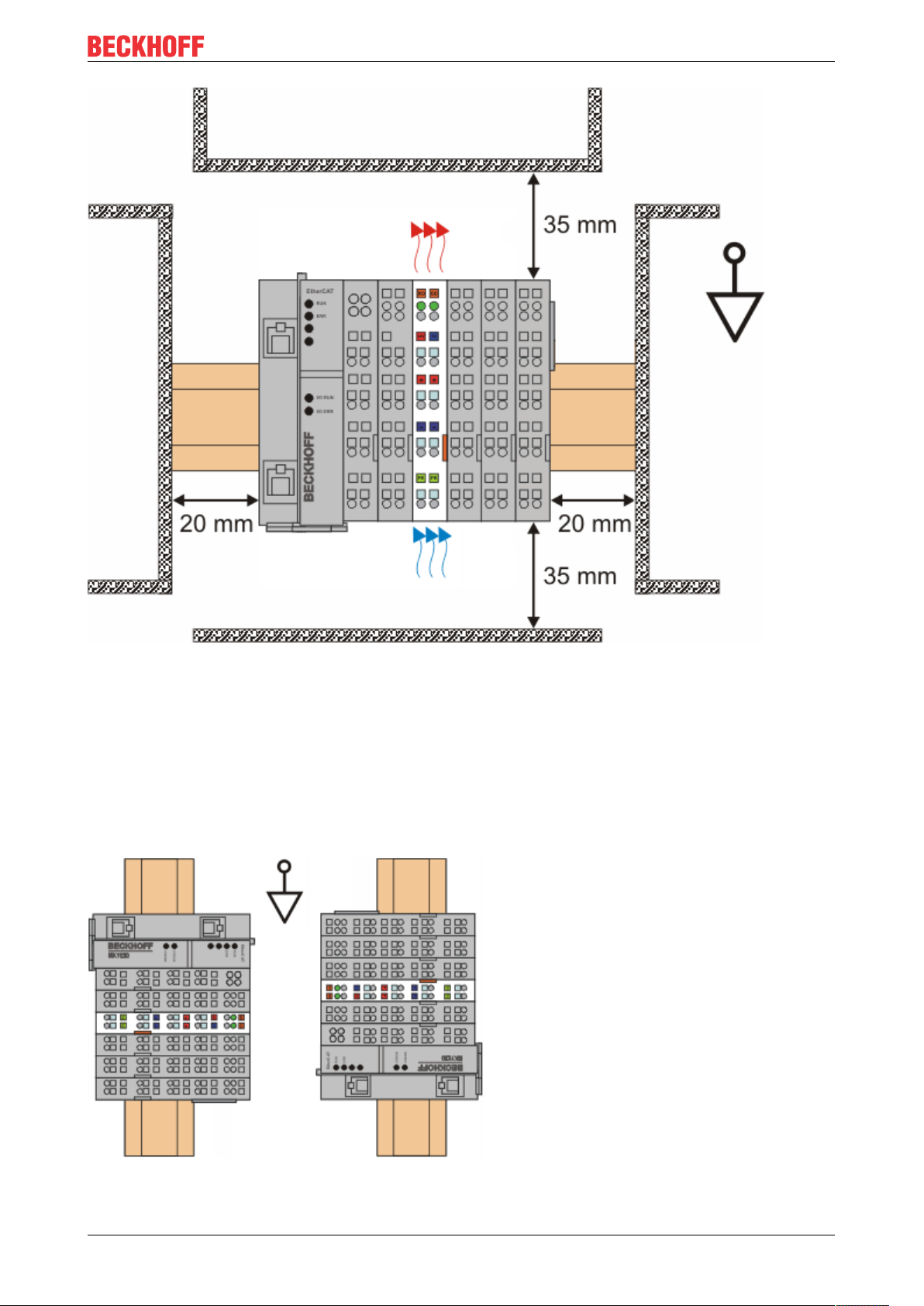
Optimum installation position (standard)
The optimum installation position requires the mounting rail to be installed horizontally and the connection
surfaces of the EL/KL terminals to face forward (see Fig. Recommended distances for standard installation
position). The terminals are ventilated from below, which enables optimum cooling of the electronics through
convection. “From below” is relative to the acceleration of gravity.
EK130026 Version: 1.1
Page 27
Mounting and wiring
Fig.19: Recommended distances for standard installation position
Compliance with the distances shown in Fig. Recommended distances for standard installation position is
recommended.
Other installation positions
All other installation positions are characterized by different spatial arrangement of the mounting rail - see
Fig Other installation positions.
The minimum distances to ambient specified above also apply to these installation positions.
EK1300 27Version: 1.1
Page 28

Mounting and wiring
Fig.20: Other installation positions
4.4 Connection system
WARNING
Risk of electric shock and damage of device!
Bring the bus terminal system into a safe, powered down state before starting installation, disassembly or
wiring of the Bus Terminals!
Overview
The Bus Terminal system offers different connection options for optimum adaptation to the respective
application:
• The terminals of KLxxxx and ELxxxx series with standard wiring include electronics and connection
level in a single enclosure.
• The terminals of KSxxxx and ESxxxx series feature a pluggable connection level and enable steady
wiring while replacing.
• The High Density Terminals (HD Terminals) include electronics and connection level in a single
enclosure and have advanced packaging density.
Standard wiring
Fig.21: Standard wiring
The terminals of KLxxxx and ELxxxx series have been tried and tested for years.
They feature integrated screwless spring force technology for fast and simple assembly.
EK130028 Version: 1.1
Page 29

Mounting and wiring
Pluggable wiring
Fig.22: Pluggable wiring
The terminals of KSxxxx and ESxxxx series feature a pluggable connection level.
The assembly and wiring procedure for the KS series is the same as for the KLxxxx and ELxxxx series.
The KS/ES series terminals enable the complete wiring to be removed as a plug connector from the top of
the housing for servicing.
The lower section can be removed from the terminal block by pulling the unlocking tab.
Insert the new component and plug in the connector with the wiring. This reduces the installation time and
eliminates the risk of wires being mixed up.
The familiar dimensions of the terminal only had to be changed slightly. The new connector adds about 3
mm. The maximum height of the terminal remains unchanged.
A tab for strain relief of the cable simplifies assembly in many applications and prevents tangling of individual
connection wires when the connector is removed.
Conductor cross sections between 0.08mm2 and 2.5mm2 can continue to be used with the proven spring
force technology.
The overview and nomenclature of the product names for KSxxxx and ESxxxx series has been retained as
known from KLxxxx and ELxxxx series.
High Density Terminals (HD Terminals)
Fig.23: High Density Terminals
The Bus Terminals from these series with 16 connection points are distinguished by a particularly compact
design, as the packaging density is twice as large as that of the standard 12mm Bus Terminals. Massive
conductors and conductors with a wire end sleeve can be inserted directly into the spring loaded terminal
point without tools.
Wiring HD Terminals
The High Density Terminals of the KLx8xx and ELx8xx series doesn't support steady wiring.
Ultrasonically "bonded" (ultrasonically welded) conductors
Ultrasonically “bonded” conductors
It is also possible to connect the Standard and High Density terminals with ultrasonically
“bonded” (ultrasonically welded) conductors. In this case, please note the tables concerning the
wire-size width [}30] below!
EK1300 29Version: 1.1
Page 30

Mounting and wiring
Wiring
Terminals for standard wiring ELxxxx/KLxxxx and for pluggable wiring ESxxxx/KSxxxx
Fig.24: Mounting a cable on a terminal connection
Up to eight connections enable the connection of solid or finely stranded cables to the Bus Terminals. The
terminals are implemented in spring force technology. Connect the cables as follows:
1. Open a spring-loaded terminal by slightly pushing with a screwdriver or a rod into the square opening
above the terminal.
2. The wire can now be inserted into the round terminal opening without any force.
3. The terminal closes automatically when the pressure is released, holding the wire securely and permanently.
Terminal housing ELxxxx, KLxxxx ESxxxx, KSxxxx
Wire size width 0.08 ... 2,5mm
2
0.08 ... 2.5mm
2
Wire stripping length 8 ... 9mm 9 ... 10mm
High Density Terminals ELx8xx, KLx8xx (HD)
The conductors of the HD Terminals are connected without tools for single-wire conductors using the direct
plug-in technique, i.e. after stripping the wire is simply plugged into the contact point. The cables are
released, as usual, using the contact release with the aid of a screwdriver. See the following table for the
suitable wire size width.
Terminal housing High Density Housing
Wire size width (conductors with a wire end sleeve) 0.14 ... 0.75mm
Wire size width (single core wires) 0.08 ... 1.5mm
Wire size width (fine-wire conductors) 0.25 ... 1.5mm
Wire size width (ultrasonically “bonded" conductors)
only 1.5mm2 (see notice [}29]!)
2
2
2
Wire stripping length 8 ... 9mm
EK130030 Version: 1.1
Page 31
Shielding
Shielding
Analog sensors and actors should always be connected with shielded, twisted paired wires.
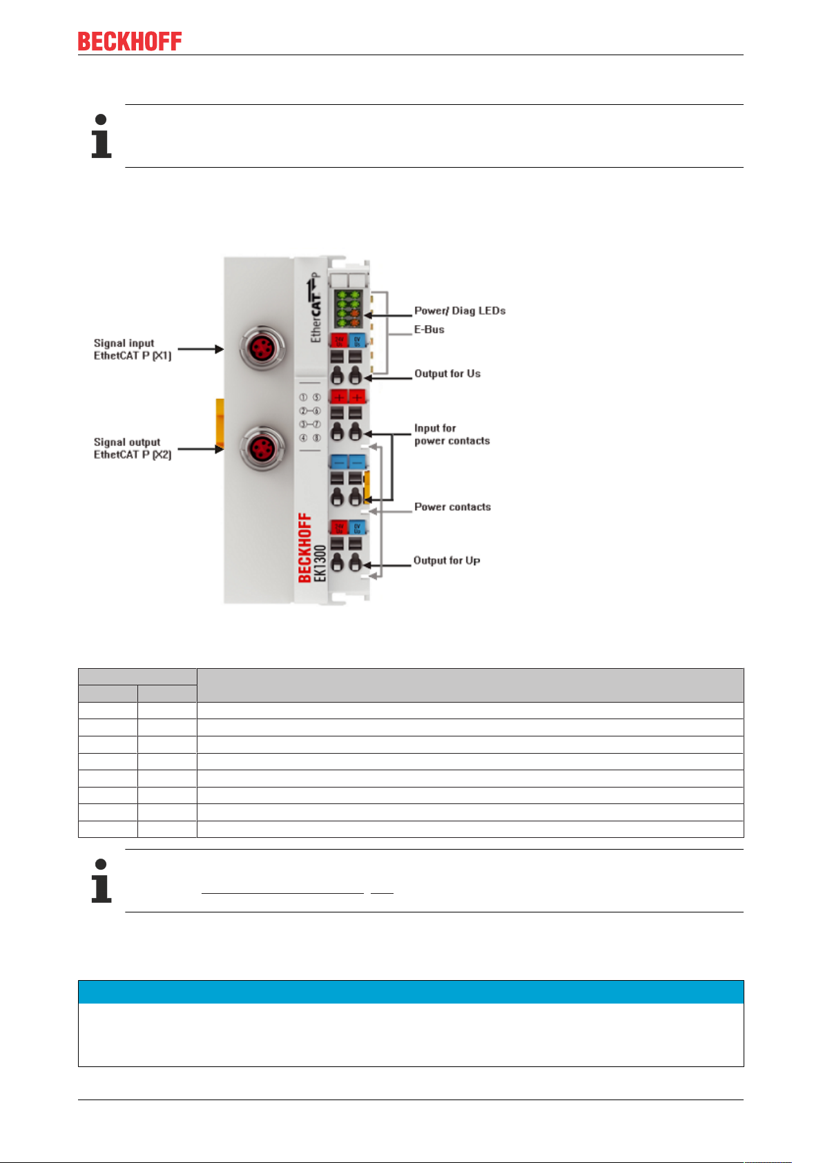
4.5 Connection EK1300
Mounting and wiring
Fig.25: EK1300 connections
Terminal point Description
Name No.
24V U
+ 2 +Feed-In power contacts (internal connected with terminal point 6)
- 3 -Feed-In power contacts (internal connected with terminal point 7)
24V U
0V U
+ 6 +Feed-In power contacts (internal connected with terminal point 2)
- 7 -Feed-In power contacts (internal connected with terminal point 3)
0V U
1 +Output US (24V System- and Sensor supply)
S
4 +Output UP (24 V power contacts)
P
5 +Output US (0V System- and Sensor supply)
S
8 +Output UP (0 V power contacts)
P
Use of US/ UP for power contacts
Please see chapter “Commissioning“ [}38] for usage of US/ UP for power contacts.
4.6 EtherCAT P connection
NOTE
Risk of damage to the device!
Bring the EtherCAT/EtherCATP system into a safe, powered down state before starting installation, disassembly or wiring of the modules!
EK1300 31Version: 1.1
Page 32
Mounting and wiring
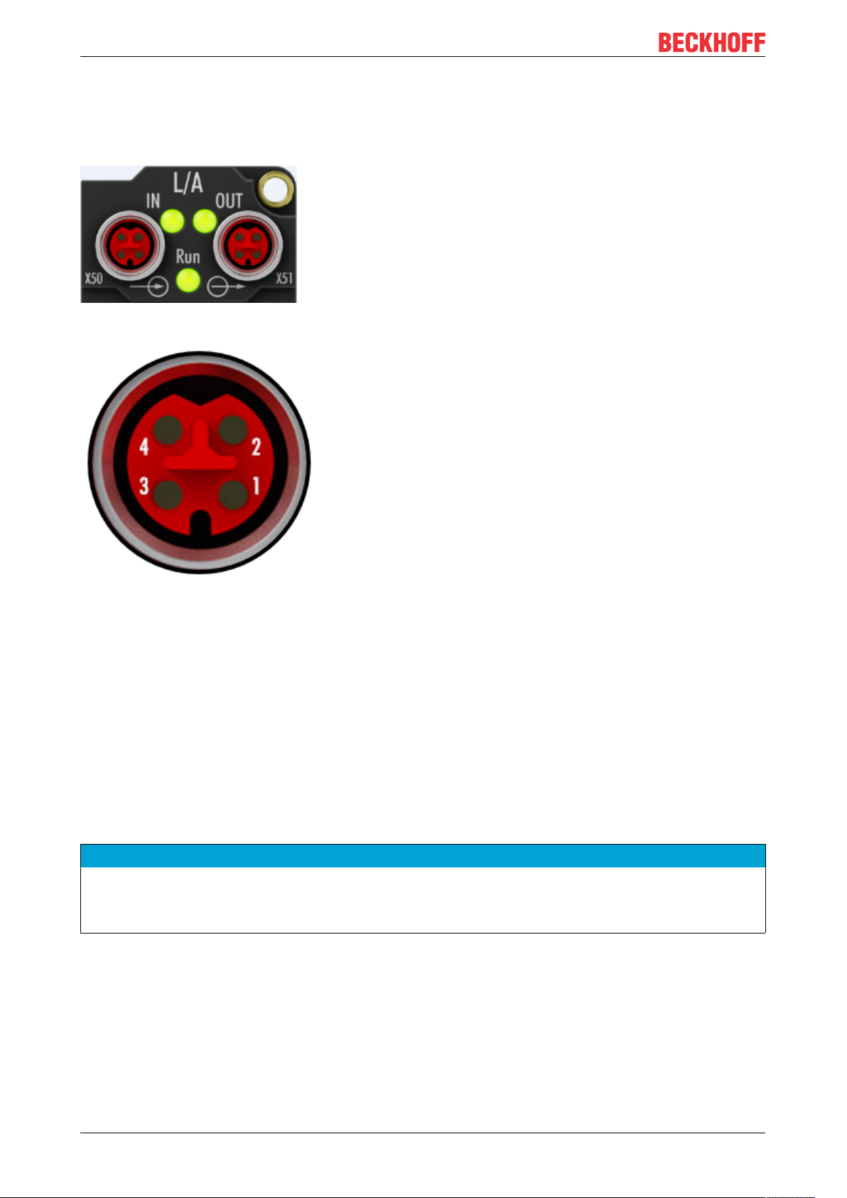
The feeding and forwarding of EtherCATP is done via two EtherCAT-P-coded M8 connectors at the top of
the modules:
• IN: left M8 connector with EtherCAT-P-coding for feeding EtherCATP
• OUT: right M8 connector with EtherCATP for forwarding the supply voltages
Fig.26: EtherCAT-P-Box, Connectors for EtherCATP
Fig.27: Pin assignment M8, EtherCATP In and EtherCATP Out
The pins M8 connectors carry a maximum current of 3A.
Two LEDs display the status of the supply voltages.
Control voltage US 24V
DC
Power is supplied to the fieldbus, the processor logic, the inputs and the sensors from the 24VDC control
voltage US.
Auxiliary voltage Up 24V
DC
The Auxiliary voltage UP supplies the digital outputs; it can be brought in separately. If the load voltage is
switched off, the fieldbus functions and the power supply and functionality of the inputs are retained.
NOTE
Pay attention to the maximum permissible current!
Pay attention also for the redirection of EtherCATP, the maximum permissible current for M8 connectors of
3A must not be exceeded!
EK130032 Version: 1.1
Page 33
Mounting and wiring
4.7 Nut torque for connectors
Fig.28: M8 EtherCAT P connector
For mounting of the M8 EtherCAT P connector the following have to be noticed:
M8 connectors
It is recommended to pull the M8 connectors tight with a nut torque of 0.4 Nm. When using the torque control
screwdriver ZB8800 is also a max. torque of 0.5Nm permissible.
Fig.29: EtherCAT Box with M8 connectors
4.8 Cabling
A list of EtherCATP cables, EtherCAT cables, power cables, sensor cables, Ethernet/EtherCAT connectors
and field-configurable connectors can be found under the following link: https://beckhoff.de/english/ethercat-
box/ethercat_box_cables.htm
You can find the corresponding data sheets at the following link: https://beckhoff.de/english/
downloadfinder/default.htm?id=109075571109075577&cat1=40717316&cat2=90800914
EtherCATP cable
For the EtherCATP connection are pre-assembled M8 cables in various lengths and the versions: plug –
open end, plug – plug or plug - socket available.
EK1300 33Version: 1.1
Page 34

Mounting and wiring
Fig.30: EtherCAT P cable: ZK700x-0100-0xxx, ZK700x-0101-0xxx and ZK700x-0102-0xxx
For connecting EtherCATP devices only shielded Ethernet cables that meet the requirements of at least
category 5 (CAT5) according to EN 50173 or ISO/IEC 11801 should be used.
Recommendations about cabling
You may get detailed recommendations about cabling EtherCAT from the documentation "Infrastructure for EtherCAT/Ethernet", that is available for download at www.Beckhoff.com.
EK130034 Version: 1.1
Page 35
Mounting and wiring
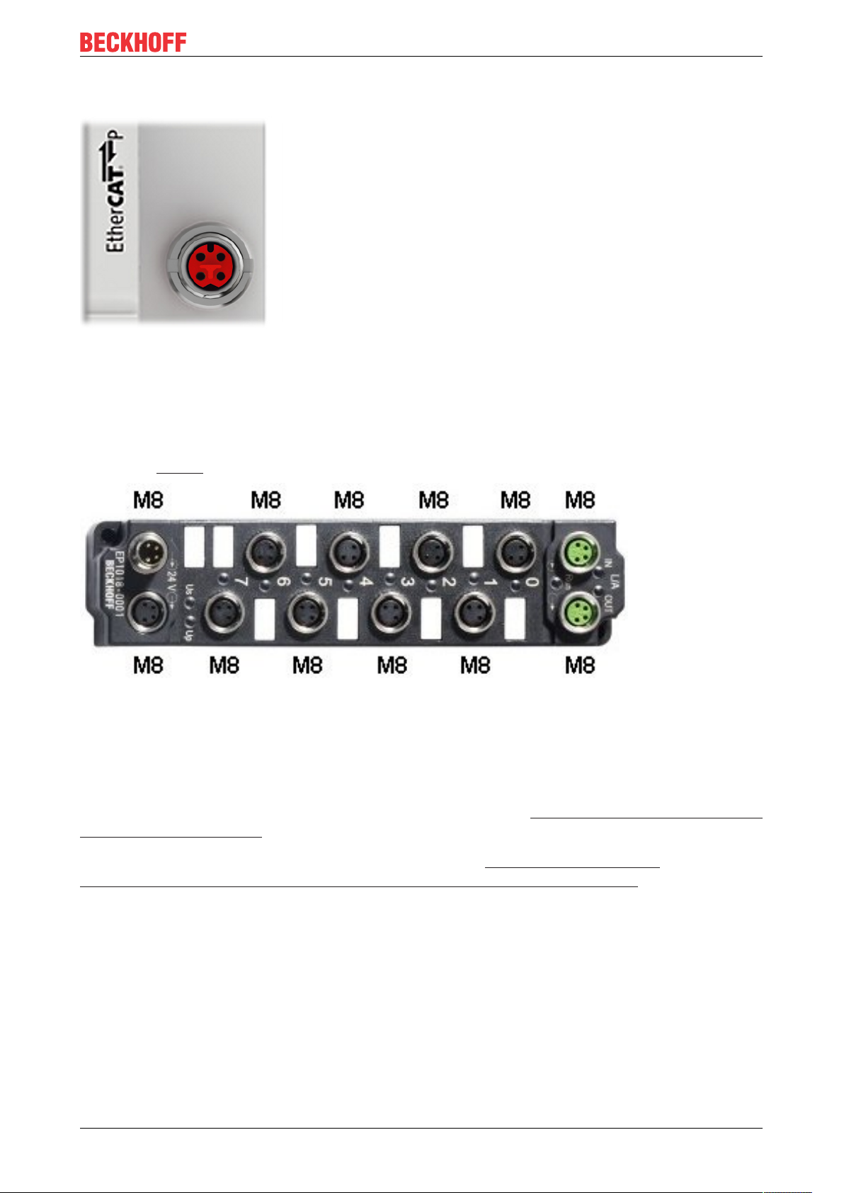
Fig.31: EtherCAT-P-Box-accessories
Number Description Link
1 Cables for EtherCAT signal in- and -output
2 Cables for EtherCAT P: Ultra-fast Communication and Power in
One Cable
3 Cables for EtherCAT signal in- and -output
4 Cables for M8 power supply
5 Cables for M8 I/O connection sockets
6 Cables for M12 I/O connection sockets
7 Shielded cables for M12 I/O connection sockets
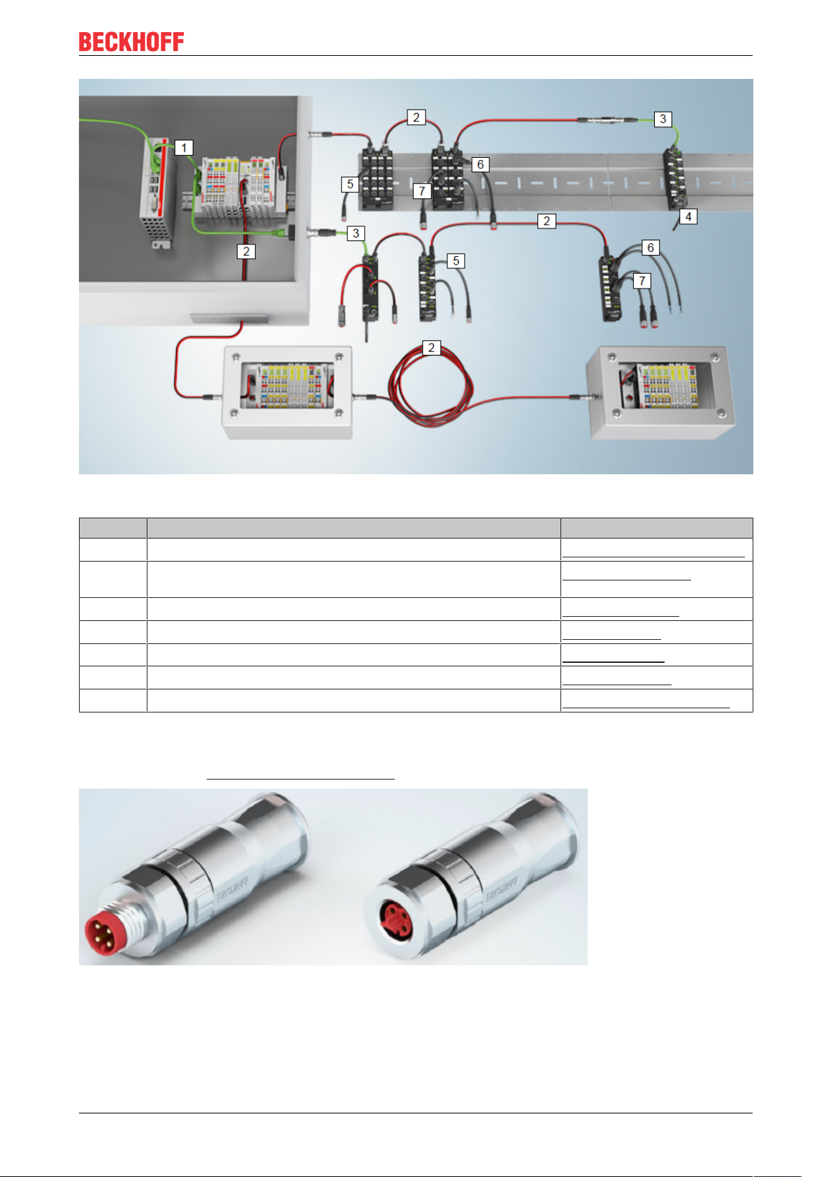
EtherCATP connectors for field assembly
For EtherCATP are field installable M8 connectors as plug and as socket available.
RJ45 EtherCAT/Ethernet cable
M8 EtherCAT P cable
M8 EtherCAT cable
M8 Power cable
M8 Sensor cable
M12 Sensor cable
M12 Sensor cable, shielded
Fig.32: EtherCAT P: field assembly connectors
EK1300 35Version: 1.1
Page 36

Mounting and wiring
Sensor cable
Fig.33: Selection of different Sensor cables from Beckhoff
EK130036 Version: 1.1
Page 37

Mounting and wiring
4.9 EtherCAT P cable conductor losses M8
When using ZK700x-xxxx-0xxx EtherCATP cables it must be ensured that the voltage at the last device is
not less than the minimum rated voltage of 20.4 V according to the standard. Variations in the output voltage
from the power supply unit must also be taken into account. This ensures that the connected consumers,
sensors and actuators are operated within the permitted voltage range.
The voltage calculation tool [}39] integrated in TwinCAT can be used for the offline calculation of the cable
lengths.
The EPP9022-0060 box with diagnostics can be used for checking during operation.
Conductor losses on the EtherCATP cables
Fig.34: Conductor losses on the EtherCATP cables
Example
A 10 meter-long EtherCATP cable with a cross section of 0.34mm² has a voltage drop of ∼3.0V with a load
of 3A.
EK1300 37Version: 1.1
Page 38

Commissioning
5 Commissioning
Use of US/ UP of the coupler
The outfeed of the coupler comes from the EtherCAT P signal input (X1). In addition, the coupler is powered
by this US voltage.
The connections for the supply of US/ UP can be used for the supply of the power contacts. To do this,
jumpers from the output terminal points e.g. terminal point 1 and 5 for US or terminal point 4 and 8 for UP)
must be placed on the infeed (terminal point 2/ 3 and 6/ 7). The bridges should be as short as possible.
As a result, the supply of the following terminals, which are fed from the power contacts realized. Usually, the
input modules are supplied from US and output modules from UP. If the outputs are to be switched off
separately, the outfeed UP of the coupler can be connected via a switch (S) to the infeed to supply output
modules. A separate potential supply terminal EL9110 can also be used as an infeed (see following
illustration).
Fig.35: Exemplary connection options for the supply by EK1300
5.1 EK1300 - Configuration by means of the TwinCAT System Manager
TwinCAT tree
Enter the EK1300 EtherCATP coupler as an EtherCAT P (subsequently) device in the TwinCAT System
Manager in Config mode under Devices. If the coupler is already connected to the network, it can also be
read. This will cause all the Bus Couplers with Bus Terminals and their configurations to be loaded. You can
then adapt these to meet your requirements.
EK130038 Version: 1.1
Page 39

Commissioning
Fig.36: TwinCAT tree EK1300
Meaning of the PDO identifier
PDO identifier Typ State Description
Status U
P
(Undervoltage)
Bit 0 Peripheral voltage for Actors UP >= 20.4 V, no overload/ no case of
shortcut
1 Peripheral voltage for Actors UP < 20.4 V or overload/ case of shortcut
(output current > 3 A)
Status U
S
(Undervoltage)
Bit 0 System- and Sensor supply US >= 20.4 V, no overload/ no case of
shortcut
1 System- and Sensor supply US < 20.4 V or overload/ case of shortcut
(output current > 3 A)
WcState Bit 0/1 Each datagram of the device indicates its processing state here. This
allows monitoring for correct process data communication.
InputToggle Bit 0/1 Toggles whenever new valid EtherCAT telegram was received
State UINT -
Status display of the “EtherCAT state machine” (see State, Online tab
[}44])
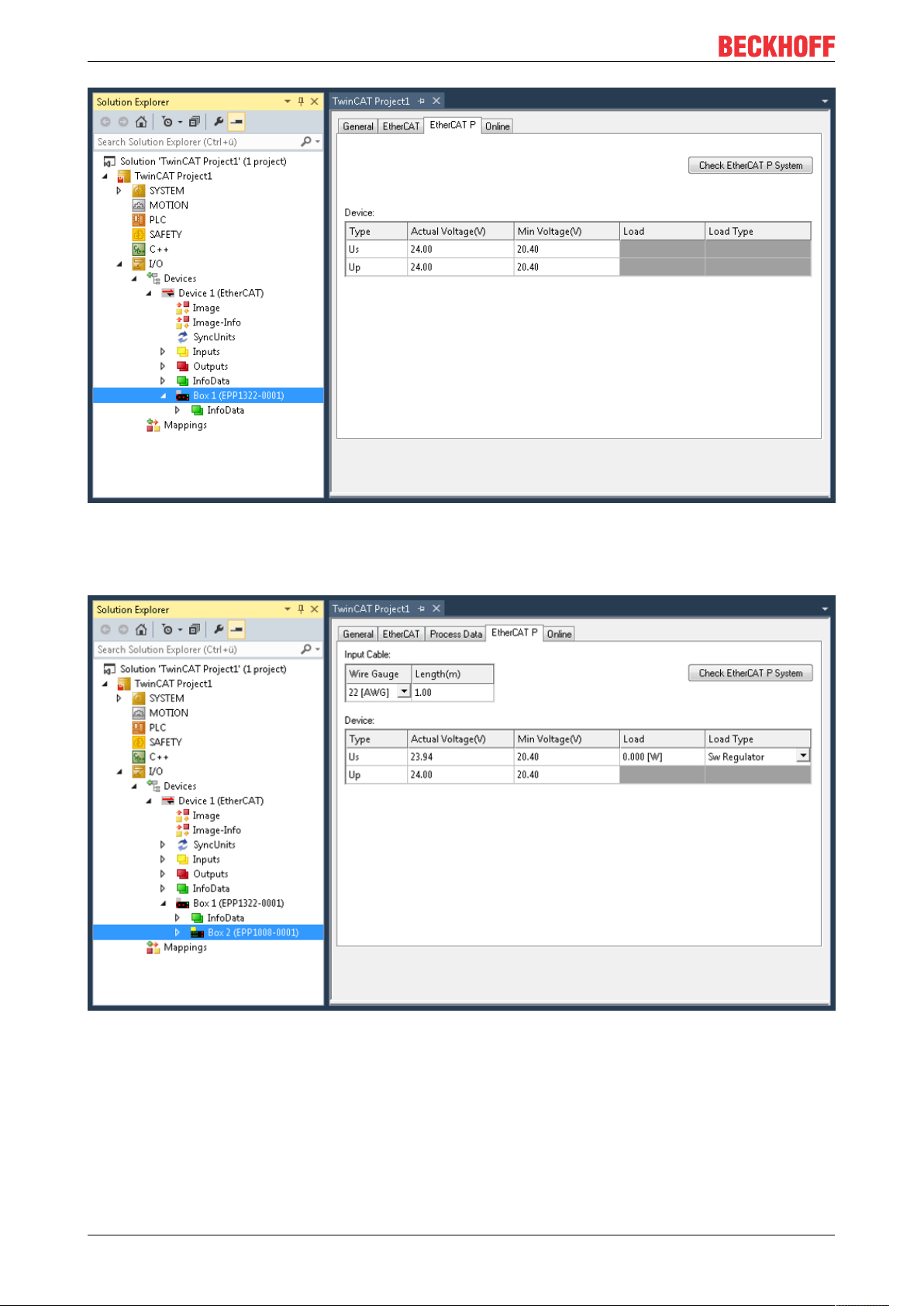
EtherCATP tab
From TwinCAT 3 Build 4020 TwinCAT has the tab “EtherCATP”. This tab contains a planning tool to
calculate voltages, currents and cable lengths of EtherCATP system. The figure below shows the tab
EtherCATP when no device is connected to the junction device (A).
EK1300 39Version: 1.1
Page 40
Commissioning
Fig.37: Tab EtherCAT P: No device connected to junction device
Is a device connected to the junction device (A), the number/letter of the ports are displayed (see figure
below, B).
Fig.38: Tab EtherCAT P: One device connected to junction device
Are three devices connected to the three ports of the junction device (A), the ports are displayed (B) as
shown in the figure below.
EK130040 Version: 1.1
Page 41
Commissioning
Fig.39: Tab EtherCAT P: Three devices connected to junction device
How you can see the topology of your EtherCATP system in TwinCAT, is described here [}44].
EK1300 41Version: 1.1
Page 42

Commissioning
Port Identification of the ports with numbers / letters as described before
Wire Gauge Selection of the wire cross-sectional area of the cable which is to be used
AWG 22 = 0.34mm²
AWG 24 = 0.22mm²
AWG 26 = 0.14mm²
Length (m) Indication of the cable length which is to be used
Check EtherCATP
system
Type Listing of two voltages: Box supply US, Auxiliary voltage U
At least one device is connected to the controller, the connected EtherCATP system
can be checked.
P
Actual Voltage (V) The respective voltage at which the system is powered, can be entered manually.
The default setting is 24.00V.
Min. Voltage (V) The minimum voltage is preset by the device and described in the ESI file. The
EtherCATP system is to be interpreted after this voltage. It is valid not to fall short
this voltage.
Internal Load (A) The current which consume the device is read from the ESI file of the respective box.
Load (A) The total consumption of the connected sensors / actuators at the device can be
specified here,e.g. 100mA.
Load Type The characteristic of the load which is connected to the devices can be selected here.
Which of the three options is right for the connected load (Sw regulator, LDO,
Resistor), must be taken from the datasheet. In case of doubt please select the
default value “Sw Regulator”.
Sw Regulator: Switching regulators, consume more energy and therefore require an
efficient power supply.
LDO: Low drop voltage regulator, the energy demand is often small and the heat
dissipation is not a problem, e.g. proximity sensor.
Resistor: electronic, passive components e.g. relay, coil
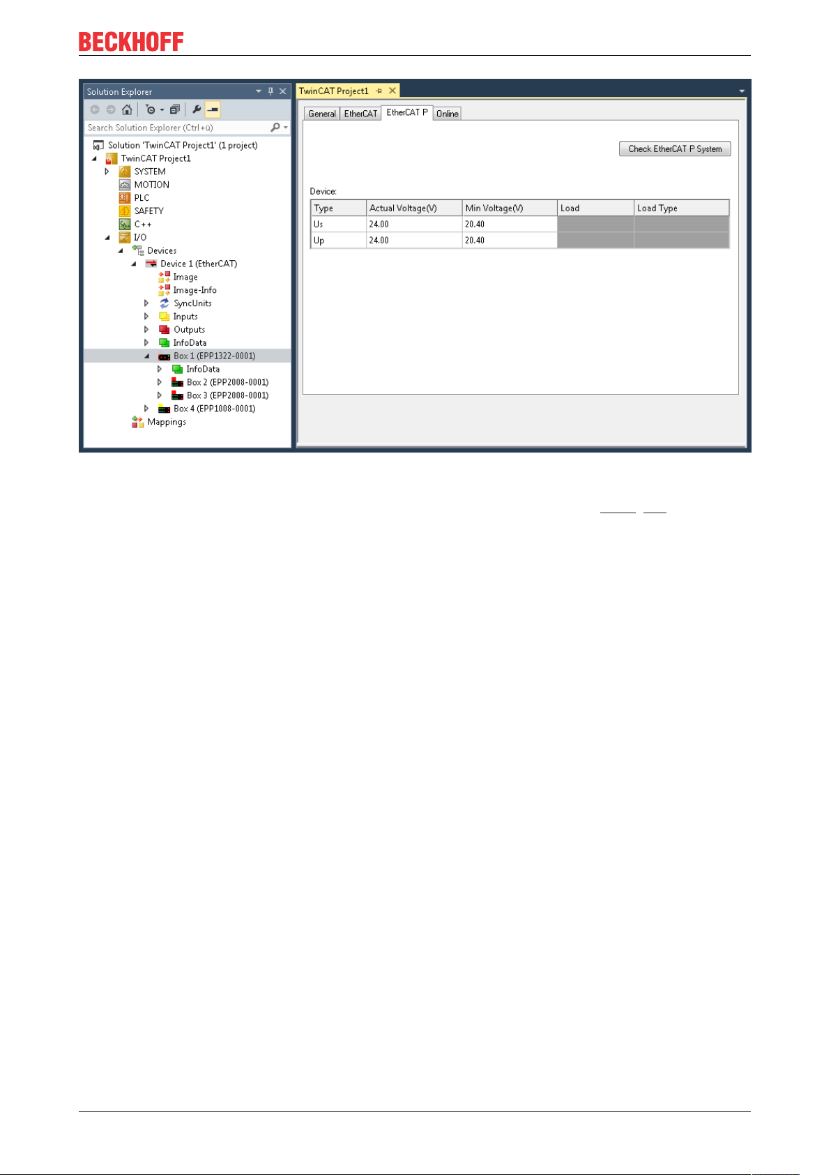
If you click on the button “Check EtherCATP System”, all devices that are attached to your TwinCAT tree
are listed as shown in the following figure.
Fig.40: Check EtherCAT P System
EK130042 Version: 1.1
Page 43
Commissioning
Check US, CheckUPSelecting which of the two voltages is to be checked.
Name Designation of the in TwinCAT tree attached devices.
Supply Voltage (V) Voltage at which the device is provided. For device 1, the voltage can be entered
manually.
Min Voltage (V) See description above.
Input Resistance
(Ω)
Current (A) Display for the current.
Load (A) See description above.
Cable Length (m) The used cable length must be entered manually.
Wire Gauge See description above.
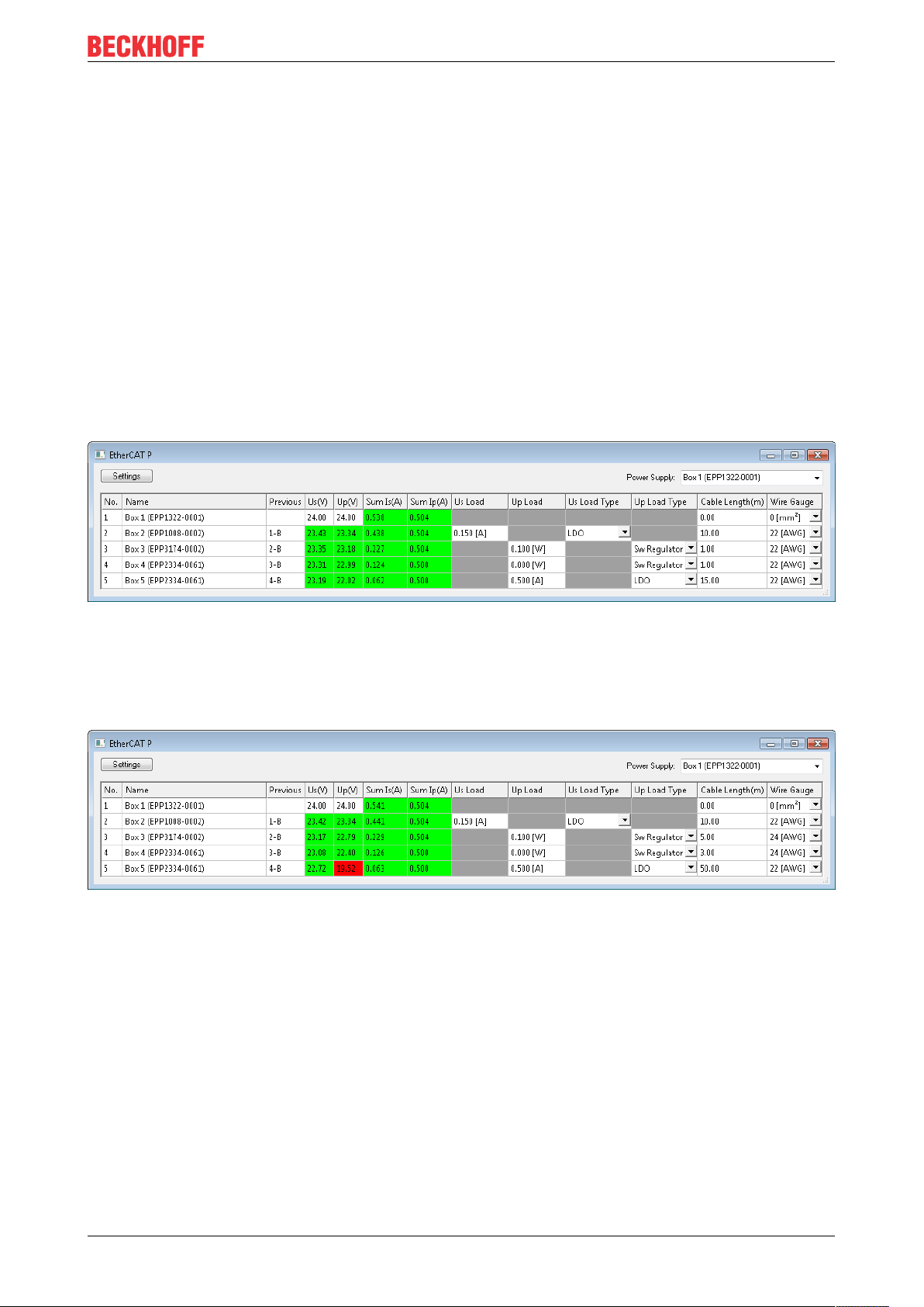
Example with problem case and troubleshooting
The following figure shows the planning of the EtherCATP system without a problem. All voltages in the
column “Supply Voltage (V)” are highlighted in green.
Input resistance, which is calculated over the cable length and cable cross-section.
Fig.41: Check EtherCAT P system without problem
The following figure shows the planning of the EtherCATP system with a problem. The “Supply Voltage (V)”
of Box 5 drops below the “Min. voltage (V)”. The corresponding field is highlighted in red. The error occurs
because longer cables (adjustable in Cable Length (m)) and also AWG 24 instead of AWG 22 cables
(adjustable in Wire Gauge) be used.
Fig.42: Check EtherCAT P System with problem
This area offers the following three options to adjust the system so that there is no error:
Provide a higher voltage: There are max. 28.8V possible.
Use an EtherCATP cable with a larger wire cross sectional area (AWG 22 instead of AWG 24).
New voltage feed.
EK1300 43Version: 1.1
Page 44

Commissioning
State, "Online" tab
Indicates the online status of the terminal.
Fig.43: State, "Online" tab
Value Description
0x___1 Slave in 'INIT' state
0x___2 Slave in 'PREOP' state
0x___3 Slave in 'BOOT' state
0x___4 Slave in 'SAFEOP' state
0x___8 Slave in 'OP' state
0x001_ Slave signals error
0x002_ Invalid vendorId, productCode... read
0x004_ Initialization error occurred
0x010_ Slave not present
0x020_ Slave signals link error
0x040_ Slave signals missing link
0x080_ Slave signals unexpected link
0x100_ Communication port A
0x200_ Communication port B
0x400_ Communication port C
0x800_ Communication port D
Topology of the EtherCATP system
You can view the topology of your EtherCATPsystem, as described in the figure below:
A: Click in the TwinCAT tree on „Device1 (EtherCAT)“
B: Click on tab „EtherCAT“
C: Click on button „Topology“
EK130044 Version: 1.1
Page 45

Commissioning
D: The topology of your EtherCATP system is displayed. Here as example: Three devices are connected to
the three ports of the distributor device.
Fig.44: Topology of the EtherCAT P system
EK1300 45Version: 1.1
Page 46

Error handling and diagnostics
6 Error handling and diagnostics
6.1 Diagnostic LED
Fig.45: EK1300
LEDs for fieldbus diagnostics
LED Display State Description
X1 L/A green off - No connection on the previous EtherCAT P strand
on link Previous EtherCAT P device connected
flashing active Communication with previous EtherCAT P device
X2 L/A green off - No connection on the subsequent EtherCAT P strand
on link Subsequent EtherCAT P device connected
flashing active Communication with subsequent EtherCAT P device
L/A E‑Bus green off - No connection internal E-bus
on linked Connection internal E-bus (Preceding terminal pass through
E‑bus)
flashing active Connection/ Communication internal E-bus (Preceding terminal
pass through E‑bus)
EK130046 Version: 1.1
Page 47

LEDs power supply diagnostics
LED Display Description
US 24V green off System- and Sensor supply US not present
on System- and Sensor supply US present
UP 24V green off Peripheral voltage for Actors UP not present
on Peripheral voltage for Actors UP present
Diag U
red off System- and Sensor supply US >= 20.4 V, no overload/ no case of
S
shortcut
on System- and Sensor supply US < 20.4 V or overload/ case of
shortcut (output current > 3 A)
Diag U
red off Peripheral voltage for Actors UP >= 20.4 V, no overload/ no case
P
of shortcut
on Peripheral voltage for Actors UP < 20.4 V or overload/ case of
shortcut (output current > 3 A)
LEDs for fieldbus diagnostics
LED Display State Description
Run green off INIT EtherCAT P module is in state Init
flashing
PREOP EtherCAT P module is in state Pre-Operational
uniformly
flashing
SAFEOP EtherCAT P module is in state Safe-Operational
slowly
on OP EtherCAT P module is in state Operational
Error handling and diagnostics
EK1300 47Version: 1.1
Page 48

Appendix
7 Appendix
7.1 EtherCAT AL Status Codes
For detailed information please refer to the EtherCAT system description.
7.2 Firmware compatibility
The EK1300 has no firmware.
7.3 Support and Service
Beckhoff and their partners around the world offer comprehensive support and service, making available fast
and competent assistance with all questions related to Beckhoff products and system solutions.
Beckhoff's branch offices and representatives
Please contact your Beckhoff branch office or representative for local support and service on Beckhoff
products!
The addresses of Beckhoff's branch offices and representatives round the world can be found on her internet
pages: https://www.beckhoff.com
You will also find further documentation for Beckhoff components there.
Beckhoff Support
Support offers you comprehensive technical assistance, helping you not only with the application of
individual Beckhoff products, but also with other, wide-ranging services:
• support
• design, programming and commissioning of complex automation systems
• and extensive training program for Beckhoff system components
Hotline: +49 5246 963 157
Fax: +49 5246 963 9157
e-mail: support@beckhoff.com
Beckhoff Service
The Beckhoff Service Center supports you in all matters of after-sales service:
• on-site service
• repair service
• spare parts service
• hotline service
Hotline: +49 5246 963 460
Fax: +49 5246 963 479
e-mail: service@beckhoff.com
Beckhoff Headquarters
Beckhoff Automation GmbH & Co. KG
EK130048 Version: 1.1
Page 49

Huelshorstweg 20
33415 Verl
Germany
Phone: +49 5246 963 0
Fax: +49 5246 963 198
e-mail: info@beckhoff.com
web:
https://www.beckhoff.com
Appendix
EK1300 49Version: 1.1
Page 50

List of illustrations
List of illustrations
Fig. 1 EL5021 EL terminal, standard IP20 IO device with serial/ batch number and revision ID (since
2014/01)....................................................................................................................................... 8
Fig. 2 EK1100 EtherCAT coupler, standard IP20 IO device with serial/ batch number......................... 9
Fig. 3 CU2016 switch with serial/ batch number.................................................................................... 9
Fig. 4 EL3202-0020 with serial/ batch number 26131006 and unique ID-number 204418 ................... 9
Fig. 5 EP1258-00001 IP67 EtherCAT Box with batch number/ date code 22090101 and unique se-
rial number 158102...................................................................................................................... 10
Fig. 6 EP1908-0002 IP67 EtherCAT Safety Box with batch number/ date code 071201FF and
unique serial number 00346070 .................................................................................................. 10
Fig. 7 EL2904 IP20 safety terminal with batch number/ date code 50110302 and unique serial num-
ber 00331701............................................................................................................................... 10
Fig. 8 ELM3604-0002 terminal with unique ID number (QR code) 100001051 and serial/ batch num-
ber 44160201............................................................................................................................... 10
Fig. 9 BIC as data matrix code (DMC, code scheme ECC200)............................................................. 11
Fig. 10 EtherCAT Telegram Structure ..................................................................................................... 15
Fig. 11 EtherCAT Topology ..................................................................................................................... 16
Fig. 12 States of the EtherCAT State Machine........................................................................................ 18
Fig. 13 From EtherCAT to EtherCATP ................................................................................................... 20
Fig. 14 Connector face: EtherCAT, Power and EtherCAT P ................................................................... 21
Fig. 15 EtherCAT P: System overview for IP 20 and IP 67 ..................................................................... 22
Fig. 16 Attaching on mounting rail ........................................................................................................... 23
Fig. 17 Disassembling of terminal............................................................................................................ 24
Fig. 18 Power contact on left side............................................................................................................ 25
Fig. 19 Recommended distances for standard installation position ........................................................ 27
Fig. 20 Other installation positions .......................................................................................................... 28
Fig. 21 Standard wiring............................................................................................................................ 28
Fig. 22 Pluggable wiring .......................................................................................................................... 29
Fig. 23 High Density Terminals................................................................................................................ 29
Fig. 24 Mounting a cable on a terminal connection ................................................................................. 30
Fig. 25 EK1300 connections.................................................................................................................... 31
Fig. 26 EtherCAT-P-Box, Connectors for EtherCATP ............................................................................ 32
Fig. 27 Pin assignment M8, EtherCATP In and EtherCATP Out ........................................................... 32
Fig. 28 M8 EtherCAT P connector........................................................................................................... 33
Fig. 29 EtherCAT Box with M8 connectors.............................................................................................. 33
Fig. 30 EtherCAT P cable: ZK700x-0100-0xxx, ZK700x-0101-0xxx and ZK700x-0102-0xxx ................. 34
Fig. 31 EtherCAT-P-Box-accessories...................................................................................................... 35
Fig. 32 EtherCAT P: field assembly connectors ...................................................................................... 35
Fig. 33 Selection of different Sensor cables from Beckhoff .................................................................... 36
Fig. 34 Conductor losses on the EtherCATP cables .............................................................................. 37
Fig. 35 Exemplary connection options for the supply by EK1300............................................................ 38
Fig. 36 TwinCAT tree EK1300 ................................................................................................................. 39
Fig. 37 Tab EtherCAT P: No device connected to junction device .......................................................... 40
Fig. 38 Tab EtherCAT P: One device connected to junction device........................................................ 40
Fig. 39 Tab EtherCAT P: Three devices connected to junction device ................................................... 41
Fig. 40 Check EtherCAT P System ......................................................................................................... 42
Fig. 41 Check EtherCAT P system without problem................................................................................ 43
EK130050 Version: 1.1
Page 51

List of illustrations
Fig. 42 Check EtherCAT P System with problem .................................................................................... 43
Fig. 43 State, "Online" tab ....................................................................................................................... 44
Fig. 44 Topology of the EtherCAT P system ........................................................................................... 45
Fig. 45 EK1300 ........................................................................................................................................ 46
EK1300 51Version: 1.1
Page 52

Page 53

More Information:
www.beckhoff.com/EK1300
Beckhoff Automation GmbH & Co. KG
Hülshorstweg 20
33415 Verl
Germany
Phone: +49 5246 9630
info@beckhoff.com
www.beckhoff.com
 Loading...