

Page 1
Documentation
EJ9576
Brake chopper module
Version:
Date:
1.1
2019-11-12
Page 2

Page 3

Table of contents
Table of contents
1 Foreword ....................................................................................................................................................5
1.1 Notes on the documentation..............................................................................................................5
1.2 Safety instructions .............................................................................................................................6
1.3 Intended use......................................................................................................................................7
1.4 Signal distribution board ....................................................................................................................7
1.5 Documentation issue status ..............................................................................................................7
1.6 Marking of EtherCAT plug-in modules...............................................................................................7
1.6.1 Beckhoff Identification Code (BIC)................................................................................... 10
1.6.2 Certificates....................................................................................................................... 12
2 System overview .....................................................................................................................................13
3 Product overview.....................................................................................................................................14
3.1 EJ9576 - Introduction ......................................................................................................................14
3.2 EJ9576 - Technical data..................................................................................................................15
3.3 EJ9576 - Pinout ...............................................................................................................................16
3.4 EJ9576 - LEDs ................................................................................................................................17
4 Installation of EJ modules ......................................................................................................................18
4.1 Power supply for the EtherCAT plug-in modules.............................................................................18
4.2 EJxxxx - dimensions........................................................................................................................20
4.3 Installation positions and minimum distances .................................................................................21
4.3.1 Minimum distances for ensuring installability................................................................... 21
4.3.2 Installation positions ........................................................................................................ 22
4.4 Codings ...........................................................................................................................................24
4.4.1 Color coding..................................................................................................................... 24
4.4.2 Mechanical position coding.............................................................................................. 25
4.5 Installation on the signal distribution board .....................................................................................26
4.6 Extension options ............................................................................................................................28
4.6.1 Using placeholder modules for unused slots ................................................................... 28
4.6.2 Linking with EtherCAT Terminals and EtherCAT Box modules via an Ethernet/EtherCAT
connection ....................................................................................................................... 29
4.7 IPC integration.................................................................................................................................30
4.8 Disassembly of the signal distribution board ...................................................................................32
5 Basics communication ...........................................................................................................................33
5.1 EtherCAT basics..............................................................................................................................33
5.2 EtherCAT devices - cabling - wired .................................................................................................33
5.3 General notes for setting the watchdog...........................................................................................34
5.4 EtherCAT State Machine.................................................................................................................36
5.5 CoE Interface...................................................................................................................................38
5.6 Distributed Clock .............................................................................................................................43
6 Commissioning........................................................................................................................................44
6.1 TwinCAT Quick Start .......................................................................................................................44
6.1.1 TwinCAT2 ....................................................................................................................... 47
6.1.2 TwinCAT 3 ....................................................................................................................... 57
6.2 TwinCAT Development Environment ..............................................................................................69
EJ9576 3Version: 1.1
Page 4

Table of contents
6.2.1 Installation of the TwinCAT real-time driver..................................................................... 69
6.2.2 Notes regarding ESI device description........................................................................... 75
6.2.3 TwinCAT ESI Updater ..................................................................................................... 79
6.2.4 Distinction between Online and Offline............................................................................ 79
6.2.5 OFFLINE configuration creation ...................................................................................... 80
6.2.6 ONLINE configuration creation ........................................................................................ 85
6.2.7 EtherCAT subscriber configuration.................................................................................. 93
6.3 General notes for commissioning of the EtherCAT slave..............................................................102
6.4 Parameterization ...........................................................................................................................111
6.5 Note on documentation EL9576 ....................................................................................................112
7 Appendix ................................................................................................................................................113
7.1 EtherCAT AL Status Codes...........................................................................................................113
7.2 EJ9576 - Firmware compatibility ...................................................................................................113
7.3 Firmware Update EL/ES/EM/ELM/EPxxxx ....................................................................................113
7.3.1 Device description ESI file/XML..................................................................................... 114
7.3.2 Firmware explanation .................................................................................................... 117
7.3.3 Updating controller firmware *.efw................................................................................. 118
7.3.4 FPGA firmware *.rbf....................................................................................................... 120
7.3.5 Simultaneous updating of several EtherCAT devices.................................................... 124
7.4 Restoring the delivery state ...........................................................................................................125
7.5 Support and Service ......................................................................................................................126
EJ95764 Version: 1.1
Page 5

Foreword
1 Foreword
1.1 Notes on the documentation
Intended audience
This description is only intended for the use of trained specialists in control and automation engineering who
are familiar with the applicable national standards.
It is essential that the documentation and the following notes and explanations are followed when installing
and commissioning these components.
It is the duty of the technical personnel to use the documentation published at the respective time of each
installation and commissioning.
The responsible staff must ensure that the application or use of the products described satisfy all the
requirements for safety, including all the relevant laws, regulations, guidelines and standards.
Disclaimer
The documentation has been prepared with care. The products described are, however, constantly under
development.
We reserve the right to revise and change the documentation at any time and without prior announcement.
No claims for the modification of products that have already been supplied may be made on the basis of the
data, diagrams and descriptions in this documentation.
Trademarks
Beckhoff®, TwinCAT®, EtherCAT®, EtherCATG®, EtherCATG10®, EtherCATP®, SafetyoverEtherCAT®,
TwinSAFE®, XFC®, XTS® and XPlanar® are registered trademarks of and licensed by Beckhoff Automation
GmbH. Other designations used in this publication may be trademarks whose use by third parties for their
own purposes could violate the rights of the owners.
Patent Pending
The EtherCAT Technology is covered, including but not limited to the following patent applications and
patents: EP1590927, EP1789857, EP1456722, EP2137893, DE102015105702 with corresponding
applications or registrations in various other countries.
EtherCAT® is registered trademark and patented technology, licensed by Beckhoff Automation GmbH,
Germany.
Copyright
© Beckhoff Automation GmbH & Co. KG, Germany.
The reproduction, distribution and utilization of this document as well as the communication of its contents to
others without express authorization are prohibited.
Offenders will be held liable for the payment of damages. All rights reserved in the event of the grant of a
patent, utility model or design.
EJ9576 5Version: 1.1
Page 6
Foreword
1.2 Safety instructions
Safety regulations
Please note the following safety instructions and explanations!
Product-specific safety instructions can be found on following pages or in the areas mounting, wiring,
commissioning etc.
Exclusion of liability
All the components are supplied in particular hardware and software configurations appropriate for the
application. Modifications to hardware or software configurations other than those described in the
documentation are not permitted, and nullify the liability of Beckhoff Automation GmbH & Co. KG.
Personnel qualification
This description is only intended for trained specialists in control, automation and drive engineering who are
familiar with the applicable national standards.
Description of instructions
In this documentation the following instructions are used.
These instructions must be read carefully and followed without fail!
DANGER
Serious risk of injury!
Failure to follow this safety instruction directly endangers the life and health of persons.
WARNING
Risk of injury!
Failure to follow this safety instruction endangers the life and health of persons.
CAUTION
Personal injuries!
Failure to follow this safety instruction can lead to injuries to persons.
NOTE
Damage to environment/equipment or data loss
Failure to follow this instruction can lead to environmental damage, equipment damage or data loss.
Tip or pointer
This symbol indicates information that contributes to better understanding.
EJ95766 Version: 1.1
Page 7

Foreword
1.3 Intended use
WARNING
Caution - Risk of injury!
EJ components may only be used for the purposes described below!
1.4 Signal distribution board
NOTE
Signal distribution board
Make sure that the EtherCAT plug-in modules are used only on a signal distribution board that has been
developed and manufactured in accordance with the Design Guide.
1.5 Documentation issue status
Version Comment
1.1 • Note Signal distribution board added
• Chapter Version identification of EtherCAT devices replaced by chapter Marking
of EtherCAT plug-in modules
• Update chapter Technical data
• Update chapter Pinout
1.0 First publication EJ9576
1.6 Marking of EtherCAT plug-in modules
Designation
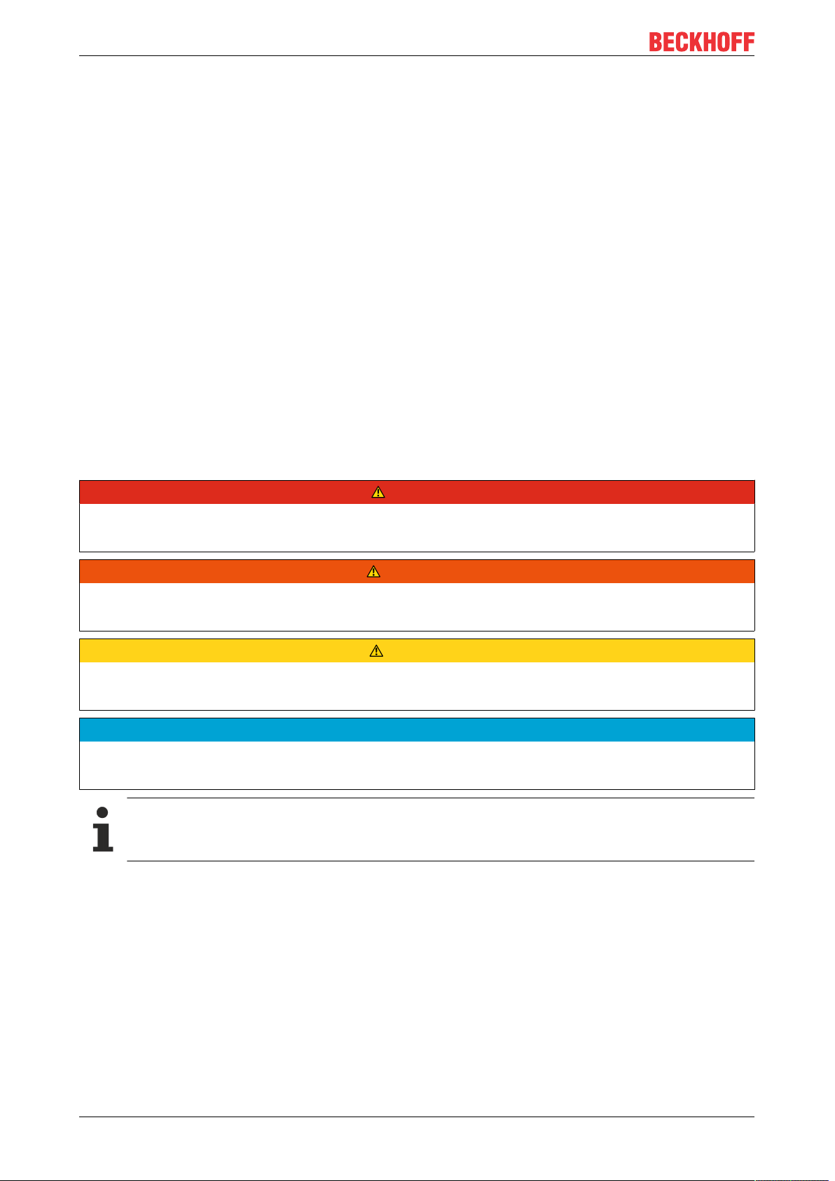
A Beckhoff EtherCAT device has a 14-digit technical designation, made up as follows (e.g.
EJ1008-0000-0017)
• Order identifier
◦ family key: EJ
◦ product designation: The first digit of product designation is used for assignment to a product
group (e.g. EJ2xxx = digital output module).
◦ Version number: The four digit version number identifies different product variants.
• Revision number:
It is incremented when changes are made to the product.
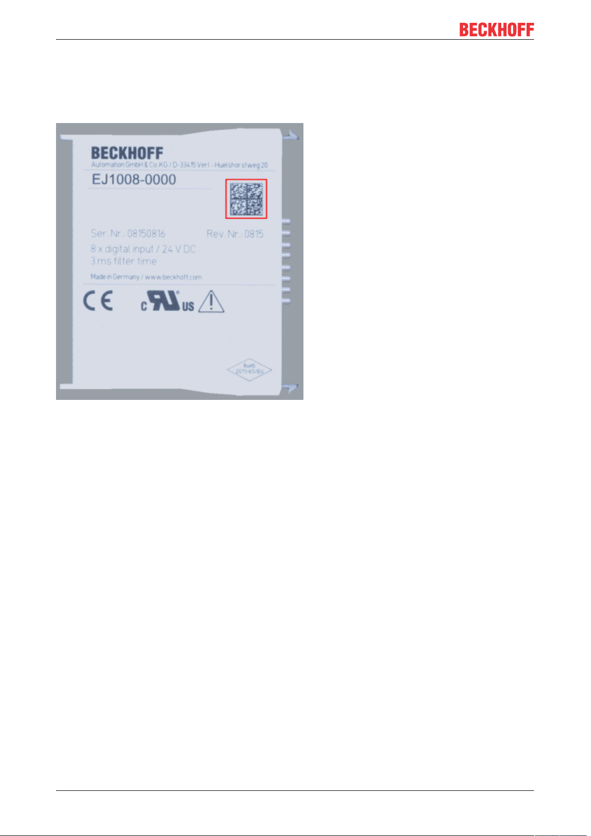
The Order identifier and the revision number are printed on the side of EtherCAT plug-in modules (s.
following illustration (A and B).
EJ9576 7Version: 1.1
Page 8
Foreword
Fig.1: Order identifier (A), Revision number (B) and serial number (C) using the example of EJ1008
Product group Example
Product designation Version Revision
EtherCAT Coupler
EJ11xx
Digital input modules
EJ1xxx
Digital output modules
EJ2xxx
Analog input modules
EJ3xxx
Analog output modules
EJ4xxx
Special function modules
EJ5xxx, EJ6xxx
Motion modules
EJ7xxx
EJ1101 -0022
EJ1008
8-channel
EJ2521
1-channel
EJ3318
8-channel thermocouple
EJ4134
4-channel
EJ6224
IO-Link master
EJ7211
servomotor
(Coupler with external connectors, power supply module and
optional ID switches
-0000
(basic type)
-0224
(2 x 24V outputs)
-0000
(basic type)
-0000
(basic type)
-0090
(with TwinSAFE SC)
-9414
(with ECT, STO and TwinSAFE SC)
Notes
• The elements mentioned above result in the technical designation. EJ1008-0000-0017 is used in the
example below.
• EJ1008-0000 is the order identifier, in the case of “-0000” usually abbreviated to EJ1008.
• The revision -0017 shows the technical progress, such as the extension of features with regard to the
EtherCAT communication, and is managed by Beckhoff.
In principle, a device with a higher revision can replace a device with a lower revision, unless specified
otherwise, e.g. in the documentation.
Associated and synonymous with each revision there is usually a description (ESI, EtherCAT Slave
Information) in the form of an XML file, which is available for download from the Beckhoff web site.
• The product designation, version and revision are read as decimal numbers, even if they are
technically saved in hexadecimal.
-0016
-0017
-0016
-0017
-0019
-0016
-0029
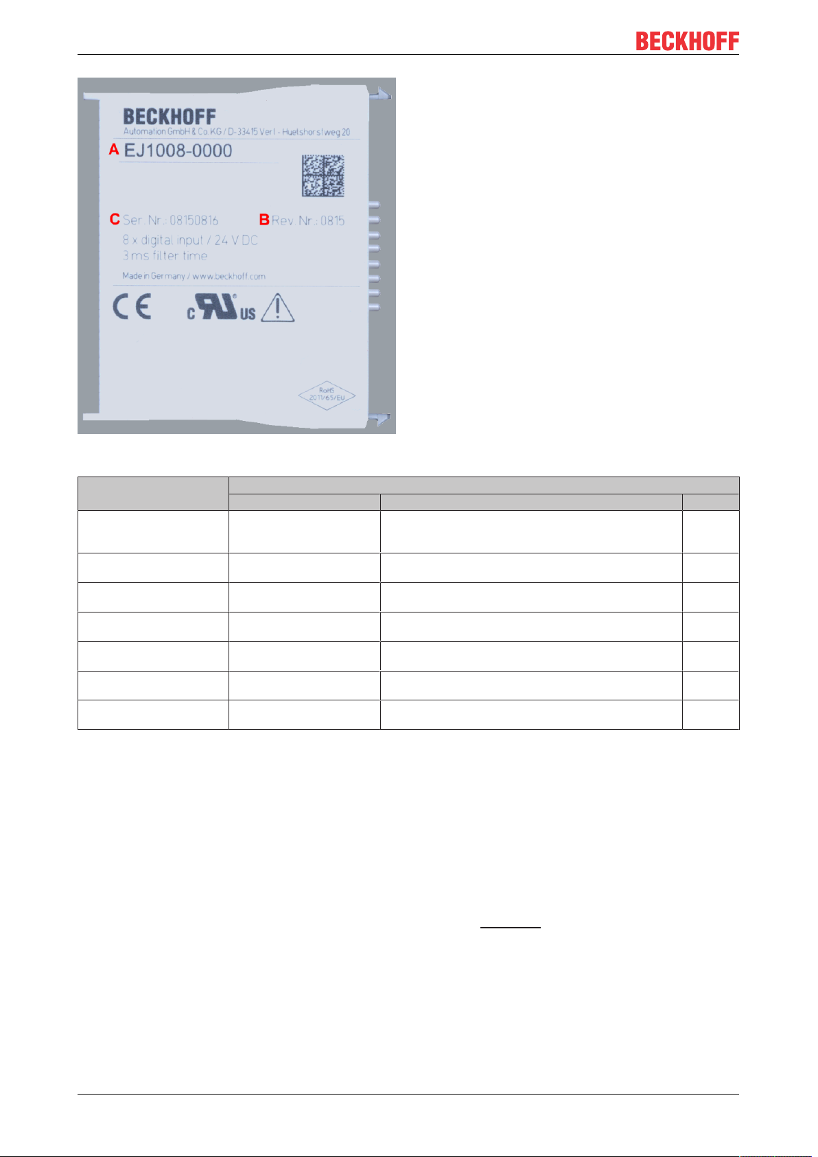
Serial number
The serial number for EtherCAT plug-in modules is usually the 8-digit number printed on the side of the
module (see following illustration C). The serial number indicates the configuration in delivery state and
therefore refers to a whole production batch, without distinguishing the individual modules of a batch.
EJ95768 Version: 1.1
Page 9
Foreword
Fig.2: Order identifier (A), revision number (B) and serial number (C) using the example of EJ1008
Serial number Example serial number: 08 15 08 16
KK - week of production (CW, calendar week) 08 - week of production: 08
YY - year of production 15 - year of production: 2015
FF - firmware version 08 -f irmware version: 08
HH - hardware version 16 - hardware version: 16
EJ9576 9Version: 1.1
Page 10
Foreword
1.6.1 Beckhoff Identification Code (BIC)
The Beckhoff Identification Code (BIC) is increasingly being applied to Beckhoff products to uniquely identify
the product. The BIC is represented as a Data Matrix Code (DMC, code scheme ECC200), the content is
based on the ANSI standard MH10.8.2-2016.
Fig.3: BIC as data matrix code (DMC, code scheme ECC200)
The BIC will be introduced step by step across all product groups.
Depending on the product, it can be found in the following places:
• on the packaging unit
• directly on the product (if space suffices)
• on the packaging unit and the product
The BIC is machine-readable and contains information that can also be used by the customer for handling
and product management.
Each piece of information can be uniquely identified using the so-called data identifier (ANSI
MH10.8.2-2016). The data identifier is followed by a character string. Both together have a maximum length
according to the table below. If the information is shorter, it shall be replaced by spaces. The data under
positions 1-4 are always available.
The following information is contained:
EJ957610 Version: 1.1
Page 11

Foreword
Item
no.
1 Beckhoff order
2 Beckhoff Traceability
3 Article description Beckhoff article
4 Quantity Quantity in packaging
5 Batch number Optional: Year and week
6 ID/serial number Optional: Present-day
7 Variant number Optional: Product variant
...
Further types of information and data identifiers are used by Beckhoff and serve internal processes.
Structure of the BIC
Type of information
number
Number (BTN)
Explanation Data iden-
tifier
Beckhoff order number 1P 8 1P072222
Unique serial number,
see note below
description, e.g. EL1008
unit, e.g. 1, 10, etc.
of production
serial number system,
e.g. with safety products
number on the basis of
standard products
S 12 SBTNk4p562d7
1K 32 1KEL1809
Q 6 Q1
2P 14 2P4015031800
51S 12 51S678294104
30P 32 30PF971 ,
Number of digits
incl. data identifier
Example
16
2*K183
Example of composite information from items 1 - 4 and 6. The data identifiers are marked in red for better
display:
BTN
An important component of the BIC is the Beckhoff Traceability Number (BTN, item no. 2). The BTN is a
unique serial number consisting of eight characters that will replace all other serial number systems at
Beckhoff in the long term (e.g. batch designations on IO components, previous serial number range for
safety products, etc.). The BTN will also be introduced step by step, so it may happen that the BTN is not yet
coded in the BIC
Notice
This information has been carefully prepared. However, the procedure described is constantly being further
developed. We reserve the right to revise and change procedures and documentation at any time and
without prior notice. No claims for changes can be made from the information, illustrations and descriptions
in this information.
EJ9576 11Version: 1.1
Page 12
Foreword
1.6.2 Certificates
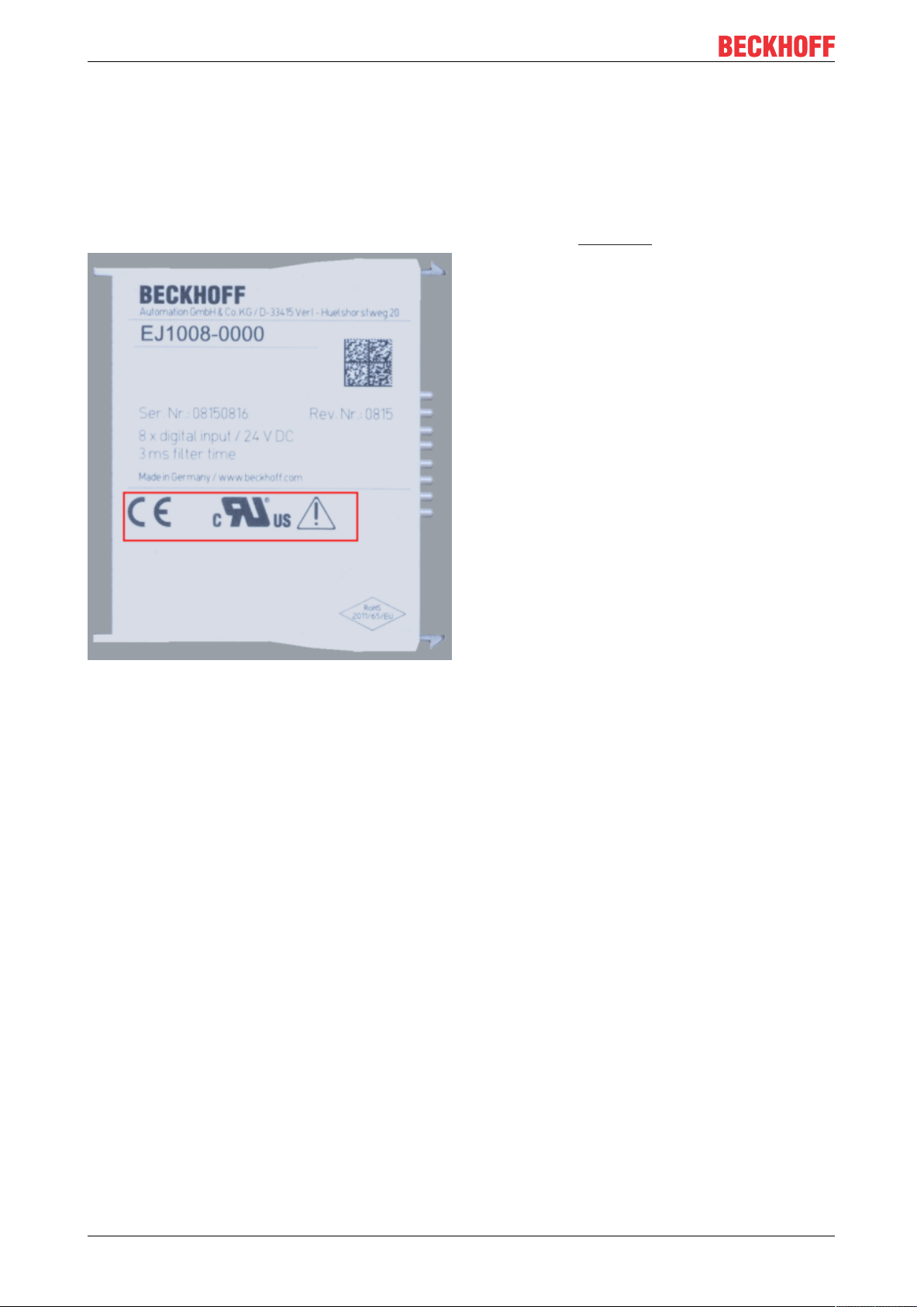
• The EhterCAT plug-in modules meet the requirements of the EMC and Low Voltage Directive. The CE
mark is printed on the side of the modules.
• The cRUus imprint identifies devices that meet product safety requirements according to U.S. and
Canadian regulations.
• The warning symbol is a request to read the corresponding documentation. The documentations for
EtherCAT plug-in modules can be downloaded from the Beckhoff homepage.
Fig.4: Marking for CE and UL using EJ1008 as an example
EJ957612 Version: 1.1
Page 13
System overview
2 System overview
Electronically, the EJxxxx EtherCAT plug-in modules are based on the EtherCAT I/O system. The EJ system
consists of the signal distribution board and EtherCAT plug-in modules. It is also possible to connect an IPC
to the EJ system.
The EJ system is suitable for mass production applications, applications with small footprint and applications
requiring a low total weight.
The machine complexity can be extended by means of the following:
• reserve slots,
• the use of placeholder modules,
• linking of EtherCAT Terminals and EtherCAT Boxes via an EtherCAT connection.
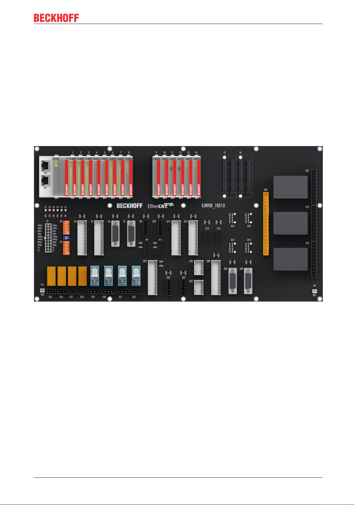
The following diagram illustrates an EJ system. The components shown are schematic, to illustrate the
functionality.
Fig.5: EJ system sample
Signal distribution board
The signal distribution board distributes the signals and the power supply to individual application-specific
plug connectors, in order to connect the controller to further machine modules. Using pre-assembled cable
harnesses avoids the need for time-consuming connection of individual wires. Coded components reduce
the unit costs and the risk of miswiring.
Beckhoff offers development of signal distribution boards as an engineering service. Customers have the
option to develop their own signal distribution board, based on the design guide.
EtherCAT plug-in modules
Similar to the EtherCAT terminal system, a module strand consists of a Bus Coupler and I/O modules.
Almost all of the EtherCAT Terminals can also be manufactured in the EJ design as EtherCAT plug-in
modules. The EJ modules are directly attached to the signal distribution board. The communication, signal
distribution and supply take place via the contact pins at the rear of the modules and the PCB tracks of the
signal distribution board. The coding pins at the rear serve as mechanical protection against incorrect
connection. Color coding on the housing facilitates distinguishing of the modules.
EJ9576 13Version: 1.1
Page 14

Product overview
3 Product overview
3.1 EJ9576 - Introduction
Fig.6: EJ9576
Brake chopper terminal
The EJ9576 power supply module contains high-performance capacitors for stabilizing supply voltages.
The EJ9576 can be used, for example, in conjunction with the EL7047 stepper motor terminal, the EJ7342
DC motor module or the EL7211-0010 servo motor module. Low internal resistance and high pulsed current
capability enable good buffering in parallel with a power supply unit.
Return currents are stored, particularly in the context of drive applications, thereby preventing overvoltages.
If the recovery energy exceeds the capacity of the capacitors, energy can be dissipated via an external
ballast resistor. The switching threshold for this can be parameterized via the TwinCAT System Manager.
EJ957614 Version: 1.1
Page 15

Product overview
3.2 EJ9576 - Technical data
Technical data EJ9576
Technology brake chopper
E-Bus current consumption typ. 85mA
Rated voltage up to 72V
Capacitance 155µF
Ripple current 10A
Internal resistance <5mΩ
Chopper voltage adjustable
Recommended ballast resistor 10Ω, 100W typ. (application-dependent)
Overvoltage control range 1V typ., parameterizable via CoE data
Ballast resistor clock rate load-dependent, max. 1ms, 2-point control
Electrical isolation 1500V (E-bus/field-side)
Diagnostics temperature on the PCB, over-/undervoltage
Special features Adjustable threshold
permissible ambient temperature range during operation 0°C .. +55°C
permissible ambient temperature range during storage -25°C .. +85°C
permissible relative humidity 95%, no condensation
Operation altitude max. 2,000m
Dimensions (W x H x D) approx. 12mm x 66mm x 55mm
Weight approx. 30g
Mounting on signal distribution board
Mounting positon
Pollution degree 2
Position of coding pins [}25]
Color coding grey
Vibration/shock resistance according to EN 60068-2-6/EN 60068-2-27, (with corresponding signal distri-
EMC immunity/emission conforms to EN 61000-6-2 / EN 61000-6-4, (with corresponding signal distri-
Protection class EJ module: IP20
Approval CE, UL
Standard [}22]
6 and 8
bution board)
bution board)
EJ system: dependent on the signal distribution board and housing
CE approval
The CE Marking refers to the EtherCAT plug-in module mentioned above.
If the EtherCAT plug-in module is used in the production of a ready-to-use end product (PCB in conjunction with a housing), the manufacturer of the end product must check compliance of the overall
system with relevant directives and CE certification.
To operate the EtherCAT plug-in modules, they must be installed in a housing.
EJ9576 15Version: 1.1
Page 16
Product overview
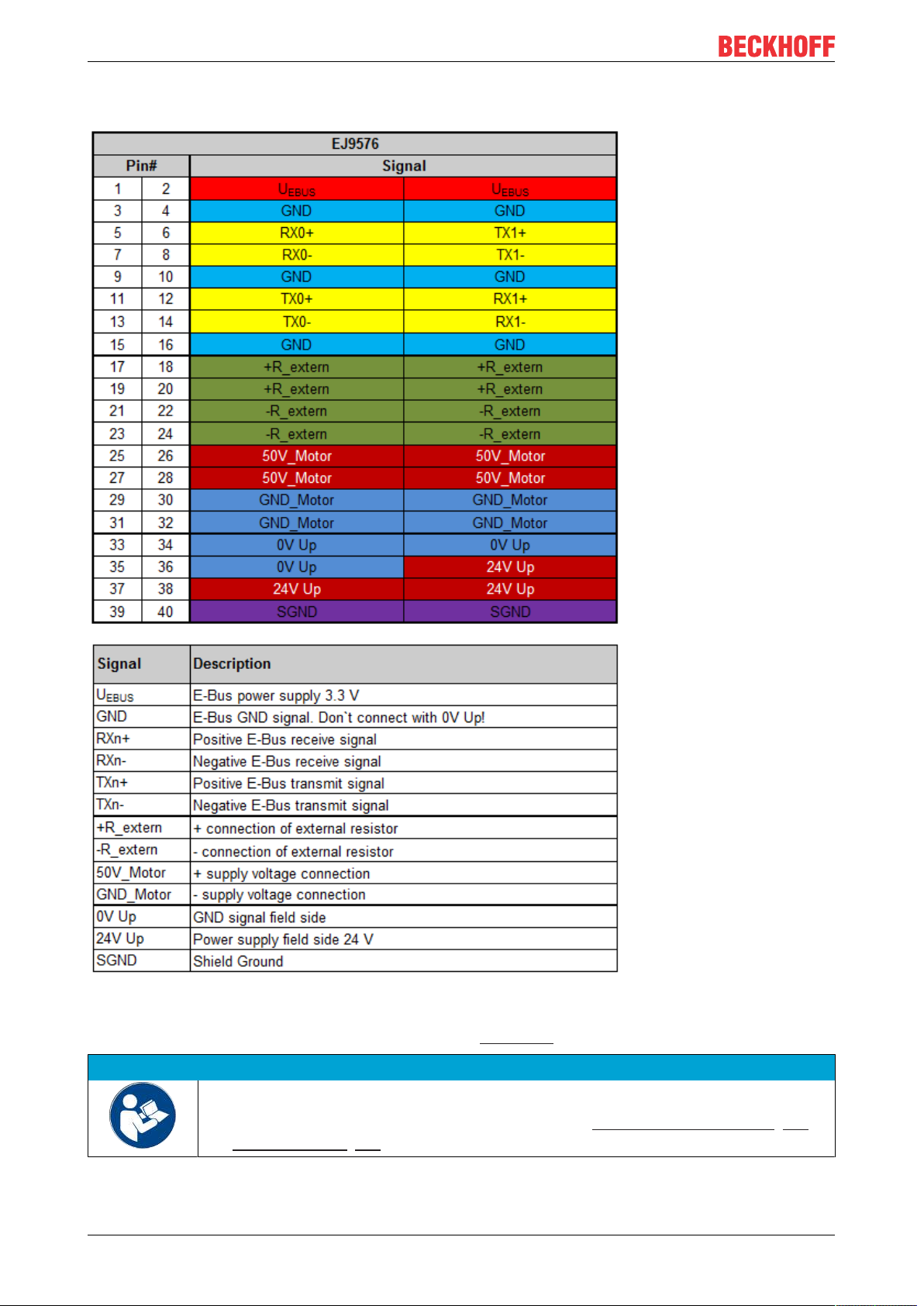
3.3 EJ9576 - Pinout
Fig.7: EJ9576 - Pinout
The PCB footprint can be downloaded from the Beckhoff homepage.
NOTE
Damage to devices possible!
Before installation and commissioning read the chapters Installation of EJ modules [}18]
and Commissioning [}44]!
EJ957616 Version: 1.1
Page 17
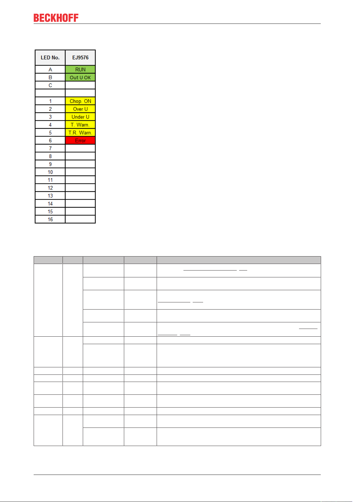
3.4 EJ9576 - LEDs
Product overview
Fig.8: EJ9576 - LEDs
LEDs
LED Color Display State Meaning
RUN green off Init
blinking Pre-
single flash Safe-
on Operational State of the EtherCAT State Machine: OP = Normal operation mode, mail-
flickering Bootstrap
Out U OK green ON - Supply voltages are OK, there are no errors
OFF - • Supply voltage is incorrect, i.e. too high or too low
Chop. ON Yellow ON - The external resistor is switched on.
Over U Yellow ON - The supply voltage has exceeded the threshold value for overvoltage.
Under U Yellow ON - The supply voltage is too low, or has fallen below the corresponding thresh-
T. Warn. Yellow ON - Temperature threshold value for the temperature on the PCB has been ex-
T. R. Warn. Yellow ON - The I2T warning level threshold value has been exceeded.
Error red ON +
Undervoltage LED
ON +
LED T.R. Warn. +
LED Over U
Operational
Operational
- The supply voltage is not connected or is so low that the supply voltage and
- There is an overtemperature in the temperature simulation for the external
State of the EtherCAT State Machine [}36]: INIT = Initialization of the terminal or BOOTSTRAP = Function for firmware updates of the terminal
State of the EtherCAT State Machine: PREOP = Setting for mailbox communication and variant standard settings
State of the EtherCAT State Machine: SAFEOP = Channel checking of the
Sync Manager [}101] and the Distributed Clocks. Outputs stay in safe oper-
ation mode.
box- and process data communication possible
State of the EtherCAT State Machine: BOOTSTRAP = function for firmware
updates [}113] of the plug-in module
• Overtemperature in the temperature simulation
• Temperature at the module too high
old value in the CoE data.
ceeded.
ResistorCurrent values cannot be read.
resistor.
EJ9576 17Version: 1.1
Page 18
Installation of EJ modules
4 Installation of EJ modules
4.1 Power supply for the EtherCAT plug-in modules
WARNING
Power supply
A SELV/PELV power supply must be used to supply power for the EJ coupler and modules. Couplers and
modules have to be connected to SELV/PELV circuits exclusively.
The signal distribution board should have a power supply designed for the maximum possible current load of
the module string. Information on the current required from the E-bus supply can be found for each module
in the respective documentation in section “Technical data“, online and in the catalog. The power
requirement of the module string is displayed in the TwinCAT System Manager (see Current consumption of
the EJ modules from the E-bus [}109]).
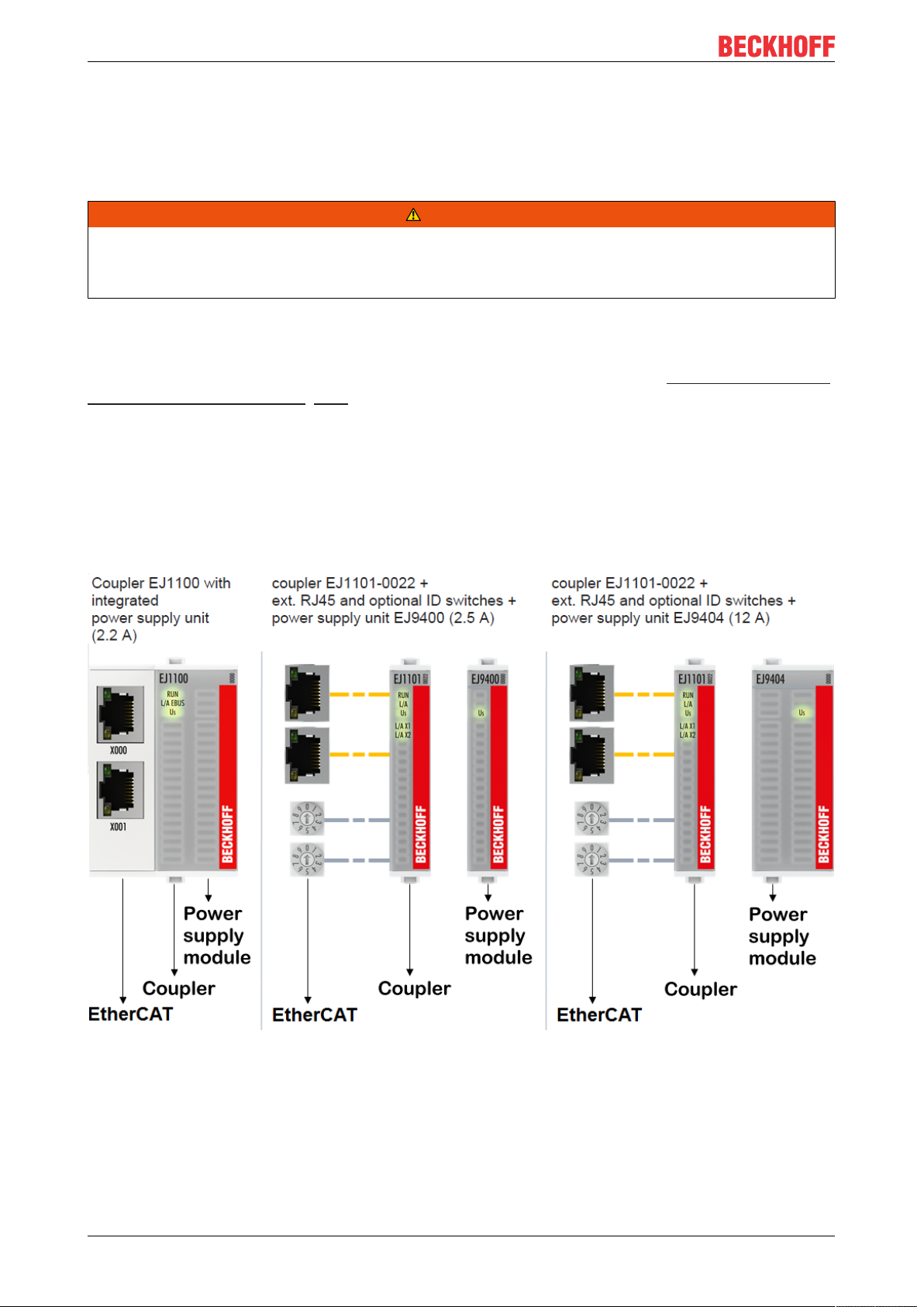
E-bus power supply with EJ1100 or EJ1101-0022 and EJ940x
The EJ1100 Bus Coupler supplies the connected EJ modules with the E-bus system voltage of 3.3V. The
Coupler can accommodate a load up to 2.2A. If a higher current is required, a combination of the coupler
EJ1101-0022 and the power supply units EJ9400 (2.5A) or EJ9404 (12A) should be used. The EJ940x
power supply units can be used as additional supply modules in the module string.
Depending on the application, the following combinations for the E-bus supply are available:
Fig.9: E-bus power supply with EJ1100 or EJ1101-0022 + EJ940x
In the EJ1101-0022 coupler, the RJ45 connectors and optional ID switches are external and can be
positioned anywhere on the signal distribution board, as required. This facilitates feeding through a housing.
The EJ940x power supply plug-in modules provide an optional reset function (see chapter Connection of the
documentation for EJ9400 and EJ9404)
EJ957618 Version: 1.1
Page 19
Installation of EJ modules
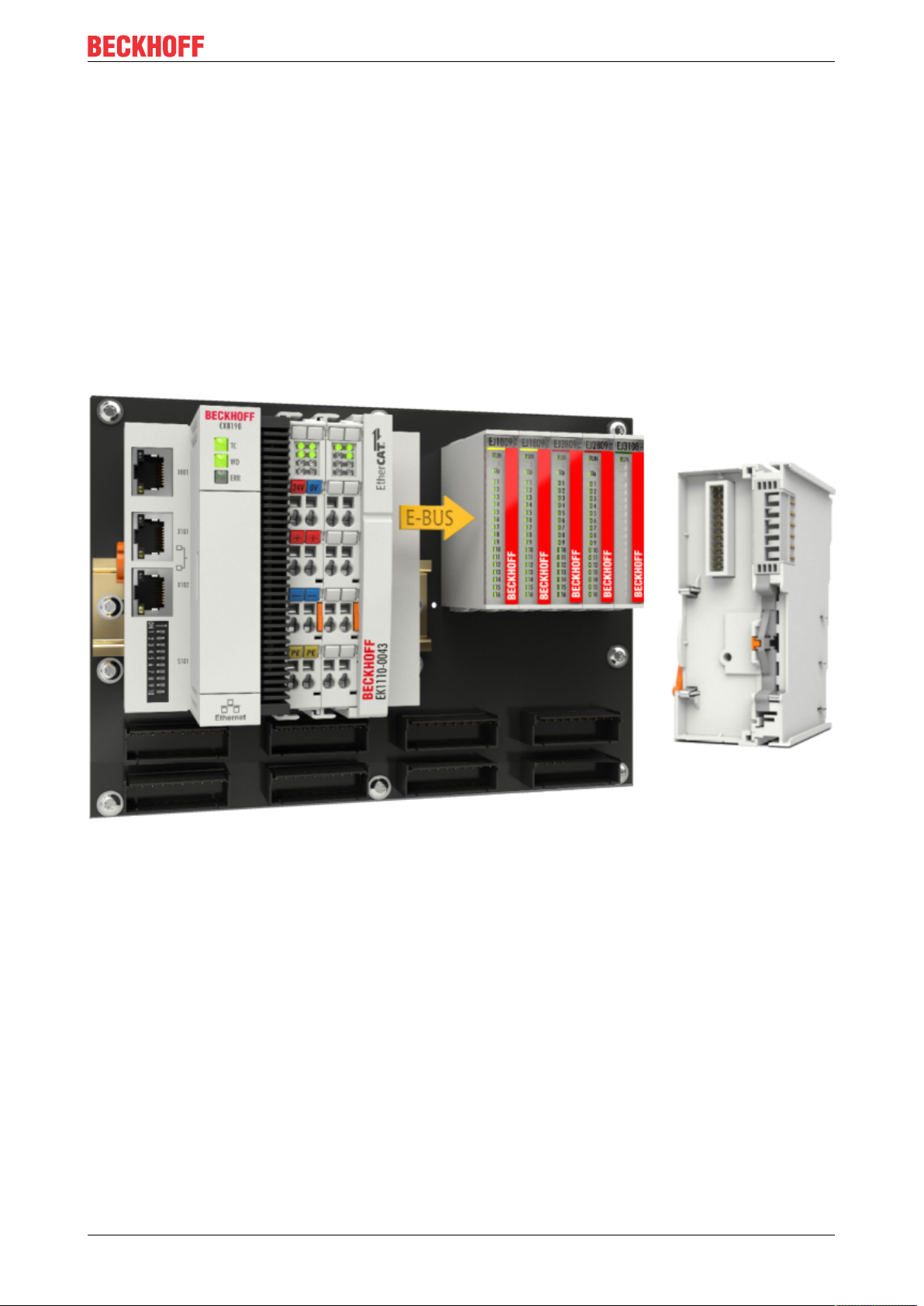
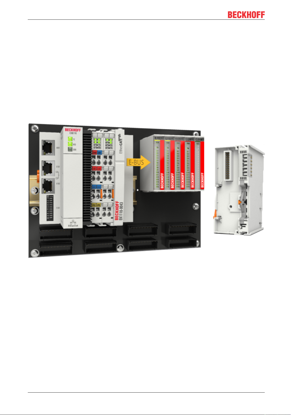
E-bus power supply with CXxxxx and EK1110-0043
The Embedded PC supplies the attached EtherCAT Terminals and the EtherCAT EJ Coupler
• with a supply voltage of 24VDC (-15 %/+20%). This voltage supplies the E-bus and the Bus Terminal
electronics.
The CXxxxx units supply the E-bus with up to 2,000mA E-bus current. If a higher current is required
due to the attached terminals, power feed terminals or power supply plug-in modules must be used for
the E-bus supply.
• with a peripheral voltage Up of 24VDC to supply the field electronics.
The EK1110-0043 EtherCAT EJ Coupler relays the following parameters to the signal distribution board via
the rear connector:
• the E-bus signals,
• the E-bus voltage U
(3.3V) and
EBUS
• the peripheral voltage UP (24VDC).
Fig.10: PCB with Embedded PC, EK1110-0043 and EJxxxx, rear view EK1110-0043
EJ9576 19Version: 1.1
Page 20
Installation of EJ modules
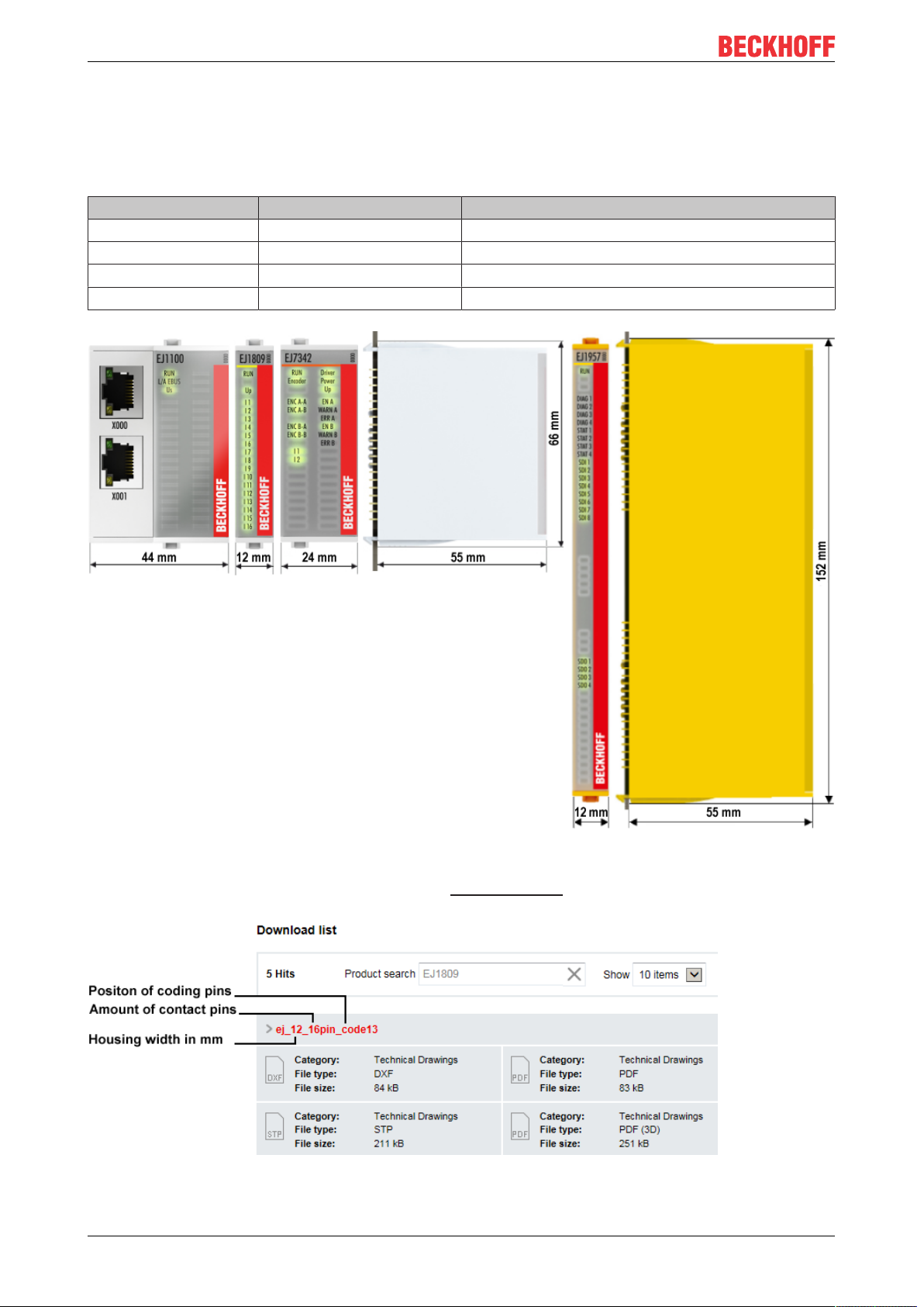
4.2 EJxxxx - dimensions
The EJ modules are compact and lightweight thanks to their design. Their volume is approx. 50% smaller
than the volume of the EL terminals. A distinction is made between four different module types, depending
on the width and the height:
Module type Dimensions (W x H x D) Sample in figure below
Coupler 44mm x 66mm x 55mm EJ1100 (ej_44_2xrj45_coupler)
Single module 12mm x 66mm x 55mm EJ1809 (ej_12_16pin_code13)
Double module 24mm x 66mm x 55mm EJ7342 (ej_24_2x16pin_code18)
Single module (long) 12mm x 152mm x 55mm EJ1957 (ej_12_2x16pin_extended_code4747)
Fig.11: EJxxxx - Dimensions
The technical drawings can be downloaded from the download finder. The drawings are named as
described in the drawing below.
Fig.12: Technical drawings from download finder
EJ957620 Version: 1.1
Page 21
Installation of EJ modules
4.3 Installation positions and minimum distances
4.3.1 Minimum distances for ensuring installability
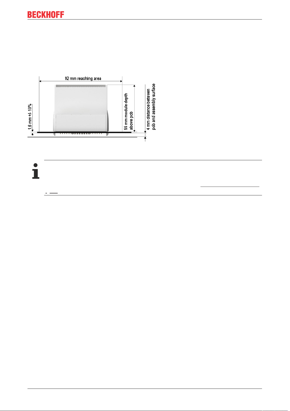
Note the dimensions shown in the following diagram for the design of the signal distribution board to ensure
safe latching and simple assembly / disassembly of the modules.
Fig.13: Mounting distances EJ module - PCB
Observing the reaching area
A minimum reaching area of 92mm is required for assembly / disassembly, in order to be able to
reach the mounting tabs with the fingers.
Adherence to the recommended minimum distances for ventilation (see section Installation position
[}22]) ensures an adequate reaching area.
The signal distribution board must have a thickness of 1.6mm and a minimum distance of 4mm from the
mounting surface, in order to ensure latching of the modules on the board.
EJ9576 21Version: 1.1
Page 22
Installation of EJ modules
4.3.2 Installation positions
NOTE
Constraints regarding installation position and operating temperature range
Please refer to the technical data [}15] for the installed components to ascertain whether any restrictions
regarding the mounting position and/or the operating temperature range have been specified. During installation of modules with increased thermal dissipation, ensure adequate distance above and below the modules to other components in order to ensure adequate ventilation of the modules during operation!
The standard installation position is recommended. If a different installation position is used, check whether
additional ventilation measures are required.
Ensure that the specified conditions (see Technical data) are adhered to!
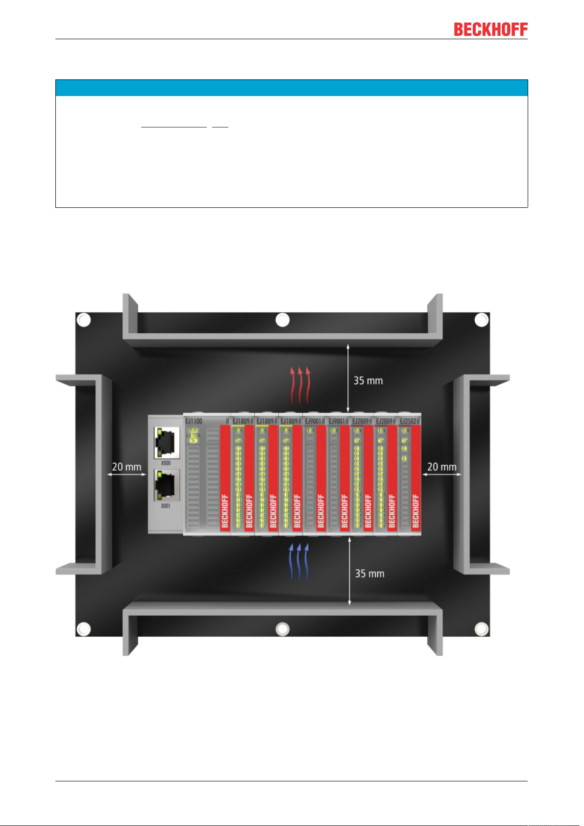
Optimum installation position (standard)
For the optimum installation position the signal distribution board is installed horizontally, and the fronts of
the EJ modules face forward (see Fig. Recommended distances for standard installation position). The
modules are ventilated from below, which enables optimum cooling of the electronics through convection.
"From below" is relative to the acceleration of gravity.
Fig.14: Recommended distances for standard installation position
Compliance with the distances shown in Fig. Recommended distances for standard installation position” is
recommend. The recommended minimum distances should not be regarded as restricted areas for other
components. The customer is responsible for verifying compliance with the environmental conditions
described in the technical data. Additional cooling measures must be provided, if required.
EJ957622 Version: 1.1
Page 23
Installation of EJ modules
Other installation positions
All other installation positions are characterized by a different spatial position of the signal distribution board,
see Fig. “Other installation positions”.
The minimum distances to ambient specified above also apply to these installation positions.
Fig.15: Other installation positions
EJ9576 23Version: 1.1
Page 24
Installation of EJ modules
4.4 Codings
4.4.1 Color coding
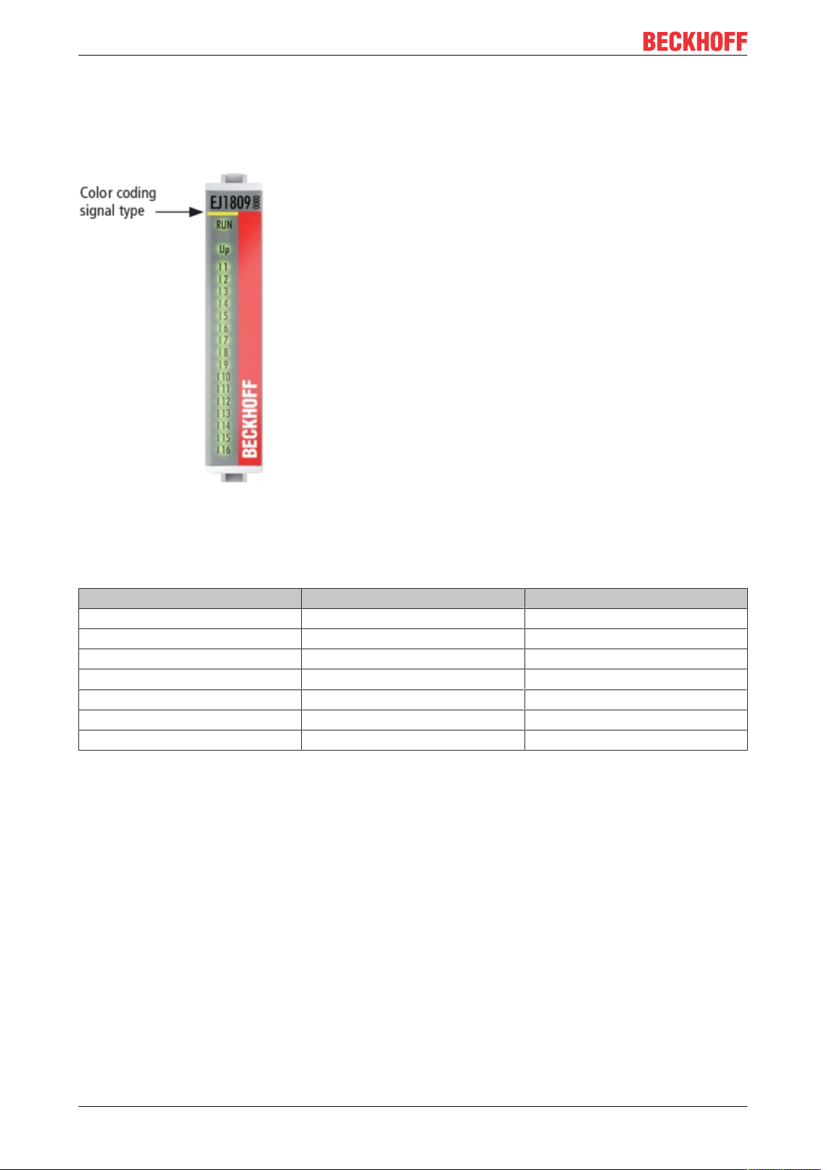
Fig.16: EJ modules color code; sample: EJ1809
The EJ modules are color-coded for a better overview in the control cabinet (see diagram above). The color
code indicates the signal type. The following table provides an overview of the signal types with
corresponding color coding.
Signal type Modules Color
Coupler EJ11xx No color coding
Digital input EJ1xxx Yellow
Digital output EJ2xxx Red
Analog input EJ3xxx Green
Analog output EJ4xxx Blue
Motion EJ7xxx orange
System EJ9xxx grey
EJ957624 Version: 1.1
Page 25
Installation of EJ modules
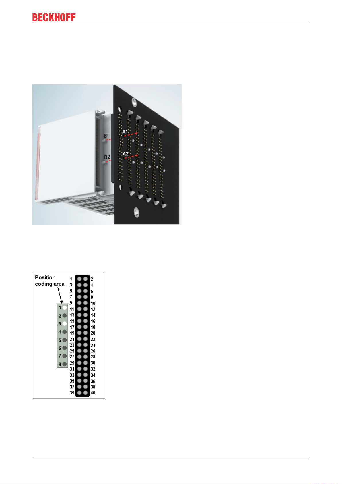
4.4.2 Mechanical position coding
The modules have two signal-specific coding pins on the underside (see Figs. B1 and B2 below). In
conjunction with the coding holes in the signal distribution board (see Figs. A1 and A2 below), the coding
pins provide an option for mechanical protection against incorrect connection. This significantly reduces the
risk of error during installation and service.
Couplers and placeholder modules have no coding pins.
Fig.17: Mechanical position coding with coding pins (B1 and B2) and coding holes (A1 and A2)
The following diagram shows the position of the position coding with position numbers on the left-hand side.
Modules with the same signal type have the same coding. For sample, all digital input modules have the
coding pins at positions one and three. There is no plug protection between modules with the same signal
type. During installation the module type should therefore be verified based on the device name.
Fig.18: Pin coding; sample: digital input modules
EJ9576 25Version: 1.1
Page 26
Installation of EJ modules
4.5 Installation on the signal distribution board
EJ modules are installed on the signal distribution board. The electrical connections between coupler and EJ
modules are realized via the pin contacts and the signal distribution board.
The EJ components must be installed in a control cabinet or enclosure which must provide protection against
fire hazards, environmental conditions and mechanical impact.
WARNING
Risk of injury through electric shock and damage to the device!
Bring the module system into a safe, de-energized state before starting installation, disassembly or wiring
of the modules.
NOTE
Risk of damage to components through electrostatic discharge!
Observe the regulations for ESD protection.
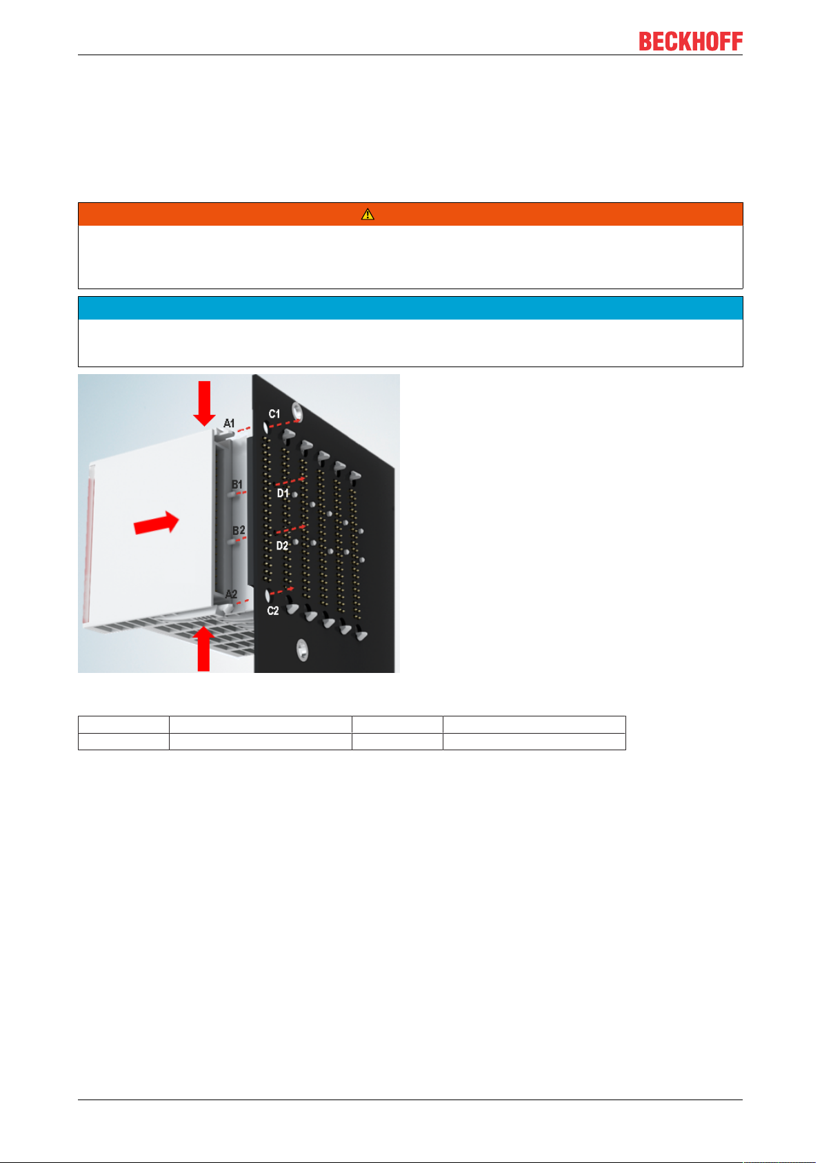
Fig.19: Installation of EJ modules
A1 / A2 Latching lugs top / bottom C1 / C2 Mounting holes
B1 / B2 Coding pins D1 / D2 Coding holes
To install the modules on the signal distribution board proceed as follows:
1. Before the installation, ensure that the signal distribution board is securely connected to the mounting
surface. Installation on an unsecured signal distribution board may result in damage to the board.
2. If necessary, check whether the positions of the coding pins (B) match the corresponding holes in the
signal distribution board (D).
3. Compare the device name on the module with the information in the installation drawing.
4. Press the upper and the lower mounting tabs simultaneously and push the module onto the board
while gently moving it up and down, until the module is latched securely.
The required contact pressure can only be established and the maximum current carrying capacity ensured if the module is latched securely.
5. Use placeholder modules (EJ9001) to fill gaps in the module strand.
EJ957626 Version: 1.1
Page 27

Installation of EJ modules
NOTE
• During installation ensure safe latching of the modules on the signal distribution board! The consequences of inadequate contact pressure include:
ð loss of quality of the transferred signals,
ð increased power dissipation of the contacts,
ð impairment of the service life.
EJ9576 27Version: 1.1
Page 28
Installation of EJ modules
4.6 Extension options
Three options are available for modifications and extensions of the EJ system.
• Replacing the placeholder modules with the function modules provided for the respective slot
• Assigning function modules specified for the respective slots for the reserve slots at the end of the
module string
• Linking with EtherCAT Terminals and EtherCAT Box modules via an Ethernet/EtherCAT connection
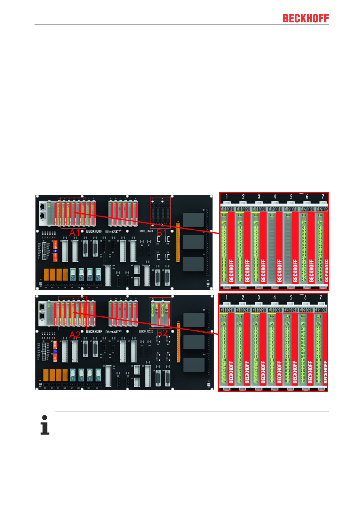
4.6.1 Using placeholder modules for unused slots
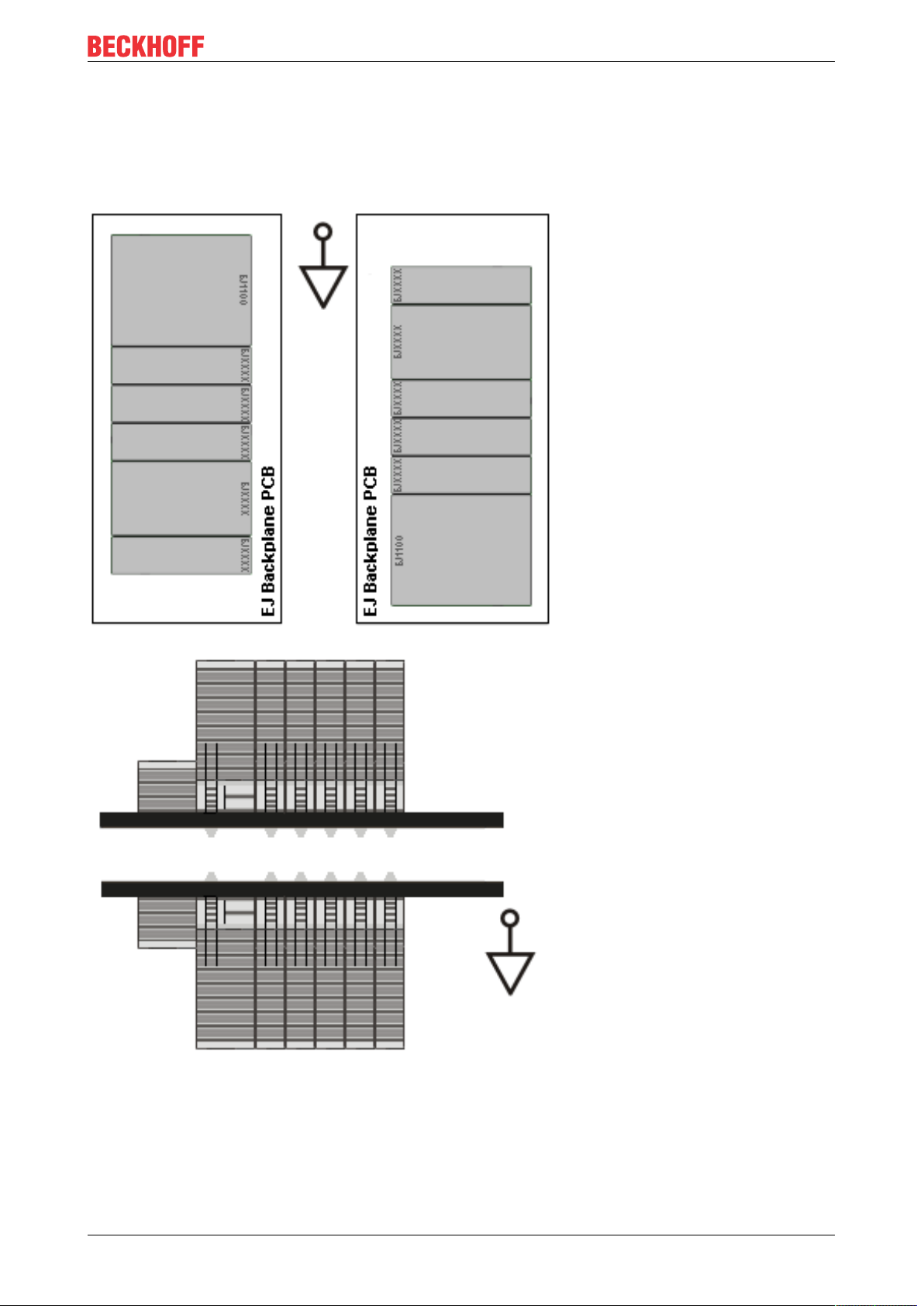
The EJ9001 placeholder modules are used to close temporary gaps in the module strands (see Fig. A1
below). In contrast to the passive terminals of the EL series, the placeholder modules actively participate in
the data exchange. Several placeholder modules can therefore be connected in series, without impairing the
data exchange.
Unused slots at the end of the module strand can be left as reserve slots (see Fig. B1 below).
The machine complexity is extended (extended version) by allocating unused slots (see Figs. A2 below Exchanging placeholder modules and B2 - Assigning reserve slots) according to the specifications for the
signal distribution board.
Fig.20: Sample: Exchanging placeholder modules and assigning reserve slots
E-bus supply
Exchange the placeholder modules with other modules changes the current input from the E-Bus.
Ensure that adequate power supply is provided.
EJ957628 Version: 1.1
Page 29
Installation of EJ modules
4.6.2 Linking with EtherCAT Terminals and EtherCAT Box modules via an Ethernet/EtherCAT connection
Example of extension via an Ethernet/EtherCAT connection
EJ9576 29Version: 1.1
Page 30
Installation of EJ modules
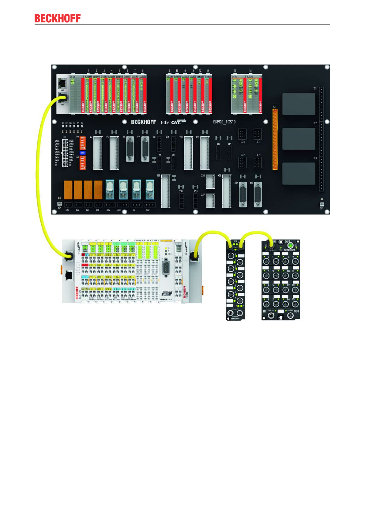
4.7 IPC integration
Connection of CX and EL terminals via the EK1110-0043 EtherCAT EJ Coupler
The EK1110-0043 EtherCAT EJ Coupler connects the compact DIN-rail PCs of the CX series and attached
EtherCAT Terminals (ELxxxx) with the EJ modules on the signal distribution board.
The EK1110-0043 is supplied from the power supply unit of the Embedded PC.
The E-bus signals and the supply voltage of the field side UP are routed directly to the PCB via a plug
connector at the rear of the EtherCAT EJ Coupler.
Due to the direct coupling of the Embedded PC and the EL terminals with the EJ modules on the PCB, no
EtherCAT extension (EK1110) or EtherCAT Coupler (EJ1100) is required.
The Embedded PC can be expanded with EtherCAT Terminals that are not yet available in the EJ system,
forexample.
Fig.21: Example PCB with Embedded PC, EK1110-0043 and EJxxxx, rear view EK1110-0043
EJ957630 Version: 1.1
Page 31

Installation of EJ modules
Connection of C6015 / C6017 via the EJ110x-00xx EtherCAT Coupler
Thanks to their ultra-compact design and versatile mounting options, the C6015 and C6017 IPCs are ideally
suited for connection to an EJ system.
In combination with the ZS5000-0003 mounting set, it is possible to place the C6015 and C6017 IPCs
compactly on the signal distribution board.
The EJ system is optimally connected to the IPC via the corresponding EtherCAT cable (see following Fig.
[A]).
The IPC can be supplied directly via the signal distribution board using the enclosed power plug (see Fig. [B]
below).
NOTE
Positioning on the signal distribution board
The dimensions and distances for placement and other details can be found in the Design
Guide and the documentation for the individual components.
The figure below shows the connection of a C6015 IPC to an EJ system as an example. The components
shown are schematic, to illustrate the functionality.
Fig.22: Example for the connection of a C6015 IPC to an EJ system
EJ9576 31Version: 1.1
Page 32

Installation of EJ modules
4.8 Disassembly of the signal distribution board
WARNING
Risk of injury through electric shock and damage to the device!
Bring the module system into a safe, de-energized state before starting installation, disassembly or wiring
of the modules.
NOTE
Risk of damage to components through electrostatic discharge!
Observe the regulations for ESD protection.
Each module is secured through latching on the distribution board, which has to be released for
disassembly.
Fig.23: Disassembly of EJ modules
To disassemble the module from the signal distribution board proceed as follows:
1. Before disassembly, ensure that the signal distribution board is securely connected to the mounting
surface. Disassembly of an unsecured signal distribution board may result in damage to the board.
2. Press the upper and lower mounting tabs simultaneously and pull the module from board while gently
moving it up and down.
EJ957632 Version: 1.1
Page 33

Basics communication
5 Basics communication
5.1 EtherCAT basics
Please refer to the EtherCAT System Documentation for the EtherCAT fieldbus basics.
5.2 EtherCAT devices - cabling - wired
The cable length between two EtherCAT devices must not exceed 100 m. This results from the FastEthernet
technology, which, above all for reasons of signal attenuation over the length of the cable, allows a maximum
link length of 5 + 90 + 5 m if cables with appropriate properties are used. See also the Design
recommendations for the infrastructure for EtherCAT/Ethernet.
Cables and connectors
For connecting EtherCAT devices only Ethernet connections (cables + plugs) that meet the requirements of
at least category 5 (CAt5) according to EN 50173 or ISO/IEC 11801 should be used. EtherCAT uses 4 wires
for signal transfer.
EtherCAT uses RJ45 plug connectors, for example. The pin assignment is compatible with the Ethernet
standard (ISO/IEC 8802-3).
Pin Color of conductor Signal Description
1 yellow TD + Transmission Data +
2 orange TD - Transmission Data -
3 white RD + Receiver Data +
6 blue RD - Receiver Data -
Due to automatic cable detection (auto-crossing) symmetric (1:1) or cross-over cables can be used between
EtherCAT devices from Beckhoff.
Recommended cables
Suitable cables for the connection of EtherCAT devices can be found on the Beckhoff website!
EJ9576 33Version: 1.1
Page 34

Basics communication
5.3 General notes for setting the watchdog
ELxxxx terminals are equipped with a safety feature (watchdog) that switches off the outputs after a
specifiable time e.g. in the event of an interruption of the process data traffic, depending on the device and
settings, e.g. in OFF state.
The EtherCAT slave controller (ESC) in the EL2xxx terminals features 2 watchdogs:
• SM watchdog (default: 100 ms)
• PDI watchdog (default: 100 ms)
SM watchdog (SyncManager Watchdog)
The SyncManager watchdog is reset after each successful EtherCAT process data communication with the
terminal. If no EtherCAT process data communication takes place with the terminal for longer than the set
and activated SM watchdog time, e.g. in the event of a line interruption, the watchdog is triggered and the
outputs are set to FALSE. The OP state of the terminal is unaffected. The watchdog is only reset after a
successful EtherCAT process data access. Set the monitoring time as described below.
The SyncManager watchdog monitors correct and timely process data communication with the ESC from the
EtherCAT side.
PDI watchdog (Process Data Watchdog)
If no PDI communication with the EtherCAT slave controller (ESC) takes place for longer than the set and
activated PDI watchdog time, this watchdog is triggered.
PDI (Process Data Interface) is the internal interface between the ESC and local processors in the EtherCAT
slave, for example. The PDI watchdog can be used to monitor this communication for failure.
The PDI watchdog monitors correct and timely process data communication with the ESC from the
application side.
The settings of the SM- and PDI-watchdog must be done for each slave separately in the TwinCAT System
Manager.
EJ957634 Version: 1.1
Page 35

Basics communication
Fig.24: EtherCAT tab -> Advanced Settings -> Behavior -> Watchdog
Notes:
• the multiplier is valid for both watchdogs.
• each watchdog has its own timer setting, the outcome of this in summary with the multiplier is a
resulting time.
• Important: the multiplier/timer setting is only loaded into the slave at the start up, if the checkbox is
activated.
If the checkbox is not activated, nothing is downloaded and the ESC settings remain unchanged.
Multiplier
Multiplier
Both watchdogs receive their pulses from the local terminal cycle, divided by the watchdog multiplier:
1/25 MHz * (watchdog multiplier + 2) = 100 µs (for default setting of 2498 for the multiplier)
The standard setting of 1000 for the SM watchdog corresponds to a release time of 100 ms.
The value in multiplier + 2 corresponds to the number of basic 40 ns ticks representing a watchdog tick.
The multiplier can be modified in order to adjust the watchdog time over a larger range.
EJ9576 35Version: 1.1
Page 36

Basics communication
Example "Set SM watchdog"
This checkbox enables manual setting of the watchdog times. If the outputs are set and the EtherCAT
communication is interrupted, the SM watchdog is triggered after the set time and the outputs are erased.
This setting can be used for adapting a terminal to a slower EtherCAT master or long cycle times. The
default SM watchdog setting is 100 ms. The setting range is 0..65535. Together with a multiplier with a range
of 1..65535 this covers a watchdog period between 0..~170 seconds.
Calculation
Multiplier = 2498 → watchdog base time = 1 / 25MHz * (2498 + 2) = 0.0001seconds = 100µs
SM watchdog = 10000 → 10000 * 100µs = 1second watchdog monitoring time
CAUTION
Undefined state possible!
The function for switching off of the SM watchdog via SM watchdog = 0 is only implemented in terminals
from version -0016. In previous versions this operating mode should not be used.
CAUTION
Damage of devices and undefined state possible!
If the SM watchdog is activated and a value of 0 is entered the watchdog switches off completely. This is
the deactivation of the watchdog! Set outputs are NOT set in a safe state, if the communication is interrupted.
5.4 EtherCAT State Machine
The state of the EtherCAT slave is controlled via the EtherCAT State Machine (ESM). Depending upon the
state, different functions are accessible or executable in the EtherCAT slave. Specific commands must be
sent by the EtherCAT master to the device in each state, particularly during the bootup of the slave.
A distinction is made between the following states:
• Init
• Pre-Operational
• Safe-Operational and
• Operational
• Boot
The regular state of each EtherCAT slave after bootup is the OP state.
EJ957636 Version: 1.1
Page 37

Fig.25: States of the EtherCAT State Machine
Basics communication
Init
After switch-on the EtherCAT slave in the Init state. No mailbox or process data communication is possible.
The EtherCAT master initializes sync manager channels 0 and 1 for mailbox communication.
Pre-Operational (Pre-Op)
During the transition between Init and Pre-Op the EtherCAT slave checks whether the mailbox was initialized
correctly.
In Pre-Op state mailbox communication is possible, but not process data communication. The EtherCAT
master initializes the sync manager channels for process data (from sync manager channel 2), the FMMU
channels and, if the slave supports configurable mapping, PDO mapping or the sync manager PDO
assignment. In this state the settings for the process data transfer and perhaps terminal-specific parameters
that may differ from the default settings are also transferred.
Safe-Operational (Safe-Op)
During transition between Pre-Op and Safe-Op the EtherCAT slave checks whether the sync manager
channels for process data communication and, if required, the distributed clocks settings are correct. Before
it acknowledges the change of state, the EtherCAT slave copies current input data into the associated DPRAM areas of the EtherCAT slave controller (ECSC).
In Safe-Op state mailbox and process data communication is possible, although the slave keeps its outputs
in a safe state, while the input data are updated cyclically.
Outputs in SAFEOP state
The default set watchdog [}34] monitoring sets the outputs of the module in a safe state - depending on the settings in SAFEOP and OP - e.g. in OFF state. If this is prevented by deactivation of the
watchdog monitoring in the module, the outputs can be switched or set also in the SAFEOP state.
Operational (Op)
Before the EtherCAT master switches the EtherCAT slave from Safe-Op to Op it must transfer valid output
data.
In the Op state the slave copies the output data of the masters to its outputs. Process data and mailbox
communication is possible.
EJ9576 37Version: 1.1
Page 38

Basics communication
Boot
In the Boot state the slave firmware can be updated. The Boot state can only be reached via the Init state.
In the Boot state mailbox communication via the file access over EtherCAT (FoE) protocol is possible, but no
other mailbox communication and no process data communication.
5.5 CoE Interface
General description
The CoE interface (CANopen over EtherCAT) is used for parameter management of EtherCAT devices.
EtherCAT slaves or the EtherCAT master manage fixed (read only) or variable parameters which they
require for operation, diagnostics or commissioning.
CoE parameters are arranged in a table hierarchy. In principle, the user has read access via the fieldbus.
The EtherCAT master (TwinCAT System Manager) can access the local CoE lists of the slaves via
EtherCAT in read or write mode, depending on the attributes.
Different CoE parameter types are possible, including string (text), integer numbers, Boolean values or larger
byte fields. They can be used to describe a wide range of features. Examples of such parameters include
manufacturer ID, serial number, process data settings, device name, calibration values for analog
measurement or passwords.
The order is specified in 2 levels via hexadecimal numbering: (main)index, followed by subindex. The value
ranges are
• Index: 0x0000 …0xFFFF (0...65535
• SubIndex: 0x00…0xFF (0...255
dez
)
dez
)
A parameter localized in this way is normally written as 0x8010:07, with preceding "x" to identify the
hexadecimal numerical range and a colon between index and subindex.
The relevant ranges for EtherCAT fieldbus users are:
• 0x1000: This is where fixed identity information for the device is stored, including name, manufacturer,
serial number etc., plus information about the current and available process data configurations.
• 0x8000: This is where the operational and functional parameters for all channels are stored, such as
filter settings or output frequency.
Other important ranges are:
• 0x4000: In some EtherCAT devices the channel parameters are stored here (as an alternative to the
0x8000 range).
• 0x6000: Input PDOs ("input" from the perspective of the EtherCAT master)
• 0x7000: Output PDOs ("output" from the perspective of the EtherCAT master)
Availability
Not every EtherCAT device must have a CoE list. Simple I/O modules without dedicated processor
usually have no variable parameters and therefore no CoE list.
If a device has a CoE list, it is shown in the TwinCAT System Manager as a separate tab with a listing of the
elements:
EJ957638 Version: 1.1
Page 39

Basics communication
Fig.26: "CoE Online " tab
The figure above shows the CoE objects available in device "EL2502", ranging from 0x1000 to 0x1600. The
subindices for 0x1018 are expanded.
Data management and function "NoCoeStorage"
Some parameters, particularly the setting parameters of the slave, are configurable and writeable. This can
be done in write or read mode
• via the System Manager (Fig. "CoE Online " tab) by clicking
This is useful for commissioning of the system/slaves. Click on the row of the index to be
parameterised and enter a value in the "SetValue" dialog.
• from the control system/PLC via ADS, e.g. through blocks from the TcEtherCAT.lib library
This is recommended for modifications while the system is running or if no System Manager or
operating staff are available.
Data management
If slave CoE parameters are modified online, Beckhoff devices store any changes in a fail-safe
manner in the EEPROM, i.e. the modified CoE parameters are still available after a restart.
The situation may be different with other manufacturers.
An EEPROM is subject to a limited lifetime with respect to write operations. From typically 100,000
write operations onwards it can no longer be guaranteed that new (changed) data are reliably saved
or are still readable. This is irrelevant for normal commissioning. However, if CoE parameters are
continuously changed via ADS at machine runtime, it is quite possible for the lifetime limit to be
reached. Support for the NoCoeStorage function, which suppresses the saving of changed CoE values, depends on the firmware version.
Please refer to the technical data in this documentation as to whether this applies to the respective
device.
• If the function is supported: the function is activated by entering the code word 0x12345678 once
in CoE 0xF008 and remains active as long as the code word is not changed. After switching the
device on it is then inactive. Changed CoE values are not saved in the EEPROM and can thus
be changed any number of times.
• Function is not supported: continuous changing of CoE values is not permissible in view of the
lifetime limit.
EJ9576 39Version: 1.1
Page 40

Basics communication
Startup list
Changes in the local CoE list of the terminal are lost if the terminal is replaced. If a terminal is replaced with a new Beckhoff terminal, it will have the default settings. It is therefore advisable to link
all changes in the CoE list of an EtherCAT slave with the Startup list of the slave, which is processed whenever the EtherCAT fieldbus is started. In this way a replacement EtherCAT slave can
automatically be parameterized with the specifications of the user.
If EtherCAT slaves are used which are unable to store local CoE values permanently, the Startup
list must be used.
Recommended approach for manual modification of CoE parameters
• Make the required change in the System Manager
The values are stored locally in the EtherCAT slave
• If the value is to be stored permanently, enter it in the Startup list.
The order of the Startup entries is usually irrelevant.
Fig.27: Startup list in the TwinCAT System Manager
The Startup list may already contain values that were configured by the System Manager based on the ESI
specifications. Additional application-specific entries can be created.
Online/offline list
While working with the TwinCAT System Manager, a distinction has to be made whether the EtherCAT
device is "available", i.e. switched on and linked via EtherCAT and therefore online, or whether a
configuration is created offline without connected slaves.
In both cases a CoE list as shown in Fig. “’CoE online’ tab” is displayed. The connectivity is shown as offline/
online.
• If the slave is offline
◦ The offline list from the ESI file is displayed. In this case modifications are not meaningful or
possible.
◦ The configured status is shown under Identity.
◦ No firmware or hardware version is displayed, since these are features of the physical device.
◦ Offline is shown in red.
EJ957640 Version: 1.1
Page 41

Basics communication
Fig.28: Offline list
• If the slave is online
◦ The actual current slave list is read. This may take several seconds, depending on the size and
cycle time.
◦ The actual identity is displayed
◦ The firmware and hardware version of the equipment according to the electronic information is
displayed
◦ Online is shown in green.
Fig.29: Online list
EJ9576 41Version: 1.1
Page 42

Basics communication
Channel-based order
The CoE list is available in EtherCAT devices that usually feature several functionally equivalent channels.
For example, a 4-channel analog 0..10 V input terminal also has 4 logical channels and therefore 4 identical
sets of parameter data for the channels. In order to avoid having to list each channel in the documentation,
the placeholder "n" tends to be used for the individual channel numbers.
In the CoE system 16 indices, each with 255 subindices, are generally sufficient for representing all channel
parameters. The channel-based order is therefore arranged in 16
dec
/10
steps. The parameter range
hex
0x8000 exemplifies this:
• Channel 0: parameter range 0x8000:00 ... 0x800F:255
• Channel 1: parameter range 0x8010:00 ... 0x801F:255
• Channel 2: parameter range 0x8020:00 ... 0x802F:255
• ...
This is generally written as 0x80n0.
Detailed information on the CoE interface can be found in the EtherCAT system documentation on the
Beckhoff website.
EJ957642 Version: 1.1
Page 43

Basics communication
5.6 Distributed Clock
The distributed clock represents a local clock in the EtherCAT slave controller (ESC) with the following
characteristics:
• Unit 1 ns
• Zero point 1.1.2000 00:00
• Size 64 bit (sufficient for the next 584 years; however, some EtherCAT slaves only offer 32-bit support,
i.e. the variable overflows after approx. 4.2 seconds)
• The EtherCAT master automatically synchronizes the local clock with the master clock in the EtherCAT
bus with a precision of < 100 ns.
For detailed information please refer to the EtherCAT system description.
EJ9576 43Version: 1.1
Page 44

Commissioning
6 Commissioning
6.1 TwinCAT Quick Start
TwinCAT is a development environment for real-time control including multi-PLC system, NC axis control,
programming and operation. The whole system is mapped through this environment and enables access to a
programming environment (including compilation) for the controller. Individual digital or analog inputs or
outputs can also be read or written directly, in order to verify their functionality, for example.
For further information please refer to http://infosys.beckhoff.com:
• EtherCAT Systemmanual:
Fieldbus Components → EtherCAT Terminals → EtherCAT System Documentation → Setup in the
TwinCAT System Manager
• TwinCAT2 → TwinCAT System Manager → I/O - Configuration
• In particular, TwinCAT driver installation:
Fieldbus components → Fieldbus Cards and Switches → FC900x – PCI Cards for Ethernet →
Installation
Devices contain the terminals for the actual configuration. All configuration data can be entered directly via
editor functions (offline) or via the "Scan" function (online):
• "offline": The configuration can be customized by adding and positioning individual components.
These can be selected from a directory and configured.
◦ The procedure for offline mode can be found under http://infosys.beckhoff.com:
TwinCAT2 → TwinCAT System Manager → IO - Configuration → Adding an I/O Device
• "online": The existing hardware configuration is read
◦ See also http://infosys.beckhoff.com:
Fieldbus components → Fieldbus cards and switches → FC900x – PCI Cards for Ethernet →
Installation → Searching for devices
The following relationship is envisaged from user PC to the individual control elements:
EJ957644 Version: 1.1
Page 45

Commissioning
Fig.30: Relationship between user side (commissioning) and installation
The user inserting of certain components (I/O device, terminal, box...) is the same in TwinCAT2 and
TwinCAT3. The descriptions below relate to the online procedure.
Sample configuration (actual configuration)
Based on the following sample configuration, the subsequent subsections describe the procedure for
TwinCAT2 and TwinCAT3:
• Control system (PLC) CX2040 including CX2100-0004 power supply unit
• Connected to the CX2040 on the right (E-bus):
EL1004 (4-channel digital input terminal 24 V DC)
• Linked via the X001 port (RJ-45): EK1100 EtherCAT Coupler
• Connected to the EK1100 EtherCAT coupler on the right (E-bus):
EL2008 (8-channel digital output terminal 24VDC;0.5A)
• (Optional via X000: a link to an external PC for the user interface)
EJ9576 45Version: 1.1
Page 46

Commissioning
Fig.31: Control configuration with Embedded PC, input (EL1004) and output (EL2008)
Note that all combinations of a configuration are possible; for example, the EL1004 terminal could also be
connected after the coupler, or the EL2008 terminal could additionally be connected to the CX2040 on the
right, in which case the EK1100 coupler wouldn’t be necessary.
EJ957646 Version: 1.1
Page 47

Commissioning
6.1.1 TwinCAT2
Startup
TwinCAT basically uses two user interfaces: the TwinCAT System Manager for communication with the
electromechanical components and TwinCAT PLC Control for the development and compilation of a
controller. The starting point is the TwinCAT System Manager.
After successful installation of the TwinCAT system on the PC to be used for development, the TwinCAT2
System Manager displays the following user interface after startup:
Fig.32: Initial TwinCAT2 user interface
Generally, TwinCAT can be used in local or remote mode. Once the TwinCAT system including the user
interface (standard) is installed on the respective PLC, TwinCAT can be used in local mode and thereby the
next step is "Insert Device [}49]".
If the intention is to address the TwinCAT runtime environment installed on a PLC as development
environment remotely from another system, the target system must be made known first. In the menu under
"Actions" → "Choose Target System...", via the symbol " " or the "F8" key, open the following window:
EJ9576 47Version: 1.1
Page 48

Commissioning
Fig.33: Selection of the target system
Use "Search (Ethernet)..." to enter the target system. Thus a next dialog opens to either:
• enter the known computer name after "Enter Host Name / IP:" (as shown in red)
• perform a "Broadcast Search" (if the exact computer name is not known)
• enter the known computer IP or AmsNetID.
Fig.34: Specify the PLC for access by the TwinCAT System Manager: selection of the target system
Once the target system has been entered, it is available for selection as follows (a password may have to be
entered):
After confirmation with "OK" the target system can be accessed via the System Manager.
EJ957648 Version: 1.1
Page 49

Commissioning
Adding devices
In the configuration tree of the TwinCAT2 System Manager user interface on the left, select "I/ODevices”
and then right-click to open a context menu and select "ScanDevices…", or start the action in the menu bar
via . The TwinCAT System Manager may first have to be set to "Configmode" via or via menu
“Actions" → "Set/Reset TwinCAT to Config Mode…" (Shift + F4).
Fig.35: Select "Scan Devices..."
Confirm the warning message, which follows, and select "EtherCAT" in the dialog:
Fig.36: Automatic detection of I/O devices: selection the devices to be integrated
Confirm the message "Find new boxes", in order to determine the terminals connected to the devices. "Free
Run" enables manipulation of input and output values in "Config mode" and should also be acknowledged.
Based on the sample configuration [}45] described at the beginning of this section, the result is as follows:
EJ9576 49Version: 1.1
Page 50

Commissioning
Fig.37: Mapping of the configuration in the TwinCAT2 System Manager
The whole process consists of two stages, which may be performed separately (first determine the devices,
then determine the connected elements such as boxes, terminals, etc.). A scan can also be initiated by
selecting "Device ..." from the context menu, which then reads the elements present in the configuration
below:
Fig.38: Reading of individual terminals connected to a device
This functionality is useful if the actual configuration is modified at short notice.
Programming and integrating the PLC
TwinCAT PLC Control is the development environment for the creation of the controller in different program
environments: TwinCAT PLC Control supports all languages described in IEC 61131-3. There are two textbased languages and three graphical languages.
• Text-based languages
◦ Instruction List (IL)
EJ957650 Version: 1.1
Page 51

◦ Structured Text (ST)
• Graphical languages
◦ Function Block Diagram (FBD)
◦ Ladder Diagram (LD)
◦ The Continuous Function Chart Editor (CFC)
◦ Sequential Function Chart (SFC)
The following section refers to Structured Text (ST).
After starting TwinCAT PLC Control, the following user interface is shown for an initial project:
Commissioning
Fig.39: TwinCAT PLC Control after startup
Sample variables and a sample program have been created and stored under the name "PLC_example.pro":
EJ9576 51Version: 1.1
Page 52

Commissioning
Fig.40: Sample program with variables after a compile process (without variable integration)
Warning 1990 (missing "VAR_CONFIG") after a compile process indicates that the variables defined as
external (with the ID "AT%I*" or "AT%Q*") have not been assigned. After successful compilation, TwinCAT
PLC Control creates a "*.tpy" file in the directory in which the project was stored. This file (*.tpy) contains
variable assignments and is not known to the System Manager, hence the warning. Once the System
Manager has been notified, the warning no longer appears.
First, integrate the TwinCAT PLC Control project in the System Manager via the context menu of the PLC
configuration; right-click and select "Append PLC Project…":
Fig.41: Appending the TwinCAT PLC Control project
EJ957652 Version: 1.1
Page 53

Commissioning
Select the PLC configuration "PLC_example.tpy" in the browser window that opens. The project including the
two variables identified with "AT" are then integrated in the configuration tree of the System Manager:
Fig.42: PLC project integrated in the PLC configuration of the System Manager
The two variables "bEL1004_Ch4" and "nEL2008_value" can now be assigned to certain process objects of
the I/O configuration.
Assigning variables
Open a window for selecting a suitable process object (PDO) via the context menu of a variable of the
integrated project "PLC_example" and via "Modify Link..." "Standard":
Fig.43: Creating the links between PLC variables and process objects
In the window that opens, the process object for the variable “bEL1004_Ch4” of type BOOL can be selected
from the PLC configuration tree:
EJ9576 53Version: 1.1
Page 54

Commissioning
Fig.44: Selecting PDO of type BOOL
According to the default setting, certain PDO objects are now available for selection. In this sample the input
of channel 4 of the EL1004 terminal is selected for linking. In contrast, the checkbox "All types" must be
ticked for creating the link for the output variables, in order to allocate a set of eight separate output bits to a
byte variable. The following diagram shows the whole process:
Fig.45: Selecting several PDOs simultaneously: activate "Continuous" and "All types"
Note that the "Continuous" checkbox was also activated. This is designed to allocate the bits contained in the
byte of the variable "nEL2008_value" sequentially to all eight selected output bits of the EL2008 terminal. In
this way it is possible to subsequently address all eight outputs of the terminal in the program with a byte
corresponding to bit 0 for channel 1 to bit 7 for channel 8 of the PLC. A special symbol ( ) at the yellow or
red object of the variable indicates that a link exists. The links can also be checked by selecting a "Goto Link
Variable” from the context menu of a variable. The object opposite, in this case the PDO, is automatically
selected:
EJ957654 Version: 1.1
Page 55

Commissioning
Fig.46: Application of a "Goto Link" variable, using "MAIN.bEL1004_Ch4" as a sample
The process of assigning variables to the PDO is completed via the menu selection "Actions" → "Generate
Mappings”, key Ctrl+M or by clicking on the symbol in the menu.
This can be visualized in the configuration:
The process of creating links can also take place in the opposite direction, i.e. starting with individual PDOs
to variable. However, in this example it would then not be possible to select all output bits for the EL2008,
since the terminal only makes individual digital outputs available. If a terminal has a byte, word, integer or
similar PDO, it is possible to allocate this a set of bit-standardised variables (type "BOOL"). Here, too, a
"Goto Link Variable” from the context menu of a PDO can be executed in the other direction, so that the
respective PLC instance can then be selected.
Activation of the configuration
The allocation of PDO to PLC variables has now established the connection from the controller to the inputs
and outputs of the terminals. The configuration can now be activated. First, the configuration can be verified
via (or via "Actions" → "Check Configuration”). If no error is present, the configuration can be
activated via (or via "Actions" → "Activate Configuration…") to transfer the System Manager settings
to the runtime system. Confirm the messages "Old configurations are overwritten!" and "Restart TwinCAT
system in Run mode" with "OK".
A few seconds later the real-time status is displayed at the bottom right in the System Manager.
The PLC system can then be started as described below.
Starting the controller
Starting from a remote system, the PLC control has to be linked with the Embedded PC over Ethernet via
"Online" → “Choose Run-Time System…":
EJ9576 55Version: 1.1
Page 56

Commissioning
Fig.47: Choose target system (remote)
In this sample "Runtime system 1 (port 801)" is selected and confirmed. Link the PLC with the real-time
system via menu option "Online" → "Login", the F11 key or by clicking on the symbol .The control
program can then be loaded for execution. This results in the message "No program on the controller!
Should the new program be loaded?", which should be acknowledged with "Yes". The runtime environment
is ready for the program start:
EJ957656 Version: 1.1
Page 57

Commissioning
Fig.48: PLC Control logged in, ready for program startup
The PLC can now be started via "Online" → "Run", F5 key or .
6.1.2 TwinCAT 3
Startup
TwinCAT makes the development environment areas available together with Microsoft Visual Studio: after
startup, the project folder explorer appears on the left in the general window area (cf. "TwinCAT System
Manager" of TwinCAT2) for communication with the electromechanical components.
After successful installation of the TwinCAT system on the PC to be used for development, TwinCAT3
(shell) displays the following user interface after startup:
EJ9576 57Version: 1.1
Page 58

Commissioning
Fig.49: Initial TwinCAT3 user interface
First create a new project via (or under "File"→“New"→ "Project…"). In the
following dialog make the corresponding entries as required (as shown in the diagram):
Fig.50: Create new TwinCAT project
The new project is then available in the project folder explorer:
EJ957658 Version: 1.1
Page 59

Commissioning
Fig.51: New TwinCAT3 project in the project folder explorer
Generally, TwinCAT can be used in local or remote mode. Once the TwinCAT system including the user
interface (standard) is installed on the respective PLC, TwinCAT can be used in local mode and thereby the
next step is "Insert Device [}60]".
If the intention is to address the TwinCAT runtime environment installed on a PLC as development
environment remotely from another system, the target system must be made known first. Via the symbol in
the menu bar:
expand the pull-down menu:
and open the following window:
Fig.52: Selection dialog: Choose the target system
EJ9576 59Version: 1.1
Page 60

Commissioning
Use "Search (Ethernet)..." to enter the target system. Thus a next dialog opens to either:
• enter the known computer name after "Enter Host Name / IP:" (as shown in red)
• perform a "Broadcast Search" (if the exact computer name is not known)
• enter the known computer IP or AmsNetID.
Fig.53: Specify the PLC for access by the TwinCAT System Manager: selection of the target system
Once the target system has been entered, it is available for selection as follows (a password may have to be
entered):
After confirmation with "OK" the target system can be accessed via the Visual Studio shell.
Adding devices
In the project folder explorer of the Visual Studio shell user interface on the left, select "Devices" within
element “I/O”, then right-click to open a context menu and select "Scan" or start the action via in the
menu bar. The TwinCAT System Manager may first have to be set to "Config mode" via or via the
menu "TwinCAT" → "Restart TwinCAT (Config mode)".
Fig.54: Select "Scan"
Confirm the warning message, which follows, and select "EtherCAT" in the dialog:
EJ957660 Version: 1.1
Page 61

Commissioning
Fig.55: Automatic detection of I/O devices: selection the devices to be integrated
Confirm the message "Find new boxes", in order to determine the terminals connected to the devices. "Free
Run" enables manipulation of input and output values in "Config mode" and should also be acknowledged.
Based on the sample configuration [}45] described at the beginning of this section, the result is as follows:
Fig.56: Mapping of the configuration in VS shell of the TwinCAT3 environment
The whole process consists of two stages, which may be performed separately (first determine the devices,
then determine the connected elements such as boxes, terminals, etc.). A scan can also be initiated by
selecting "Device ..." from the context menu, which then reads the elements present in the configuration
below:
EJ9576 61Version: 1.1
Page 62

Commissioning
Fig.57: Reading of individual terminals connected to a device
This functionality is useful if the actual configuration is modified at short notice.
Programming the PLC
TwinCAT PLC Control is the development environment for the creation of the controller in different program
environments: TwinCAT PLC Control supports all languages described in IEC 61131-3. There are two textbased languages and three graphical languages.
• Text-based languages
◦ Instruction List (IL)
◦ Structured Text (ST)
• Graphical languages
◦ Function Block Diagram (FBD)
◦ Ladder Diagram (LD)
◦ The Continuous Function Chart Editor (CFC)
◦ Sequential Function Chart (SFC)
The following section refers to Structured Text (ST).
In order to create a programming environment, a PLC subproject is added to the project sample via the
context menu of "PLC" in the project folder explorer by selecting "Add New Item….":
EJ957662 Version: 1.1
Page 63

Fig.58: Adding the programming environment in "PLC"
Commissioning
In the dialog that opens select "Standard PLC project" and enter "PLC_example" as project name, for
example, and select a corresponding directory:
Fig.59: Specifying the name and directory for the PLC programming environment
The "Main" program, which already exists by selecting "Standard PLC project", can be opened by doubleclicking on "PLC_example_project" in "POUs”. The following user interface is shown for an initial project:
EJ9576 63Version: 1.1
Page 64

Commissioning
Fig.60: Initial "Main" program of the standard PLC project
To continue, sample variables and a sample program have now been created:
EJ957664 Version: 1.1
Page 65

Commissioning
Fig.61: Sample program with variables after a compile process (without variable integration)
The control program is now created as a project folder, followed by the compile process:
Fig.62: Start program compilation
The following variables, identified in the ST/ PLC program with "AT%", are then available in under
"Assignments" in the project folder explorer:
Assigning variables
Via the menu of an instance - variables in the "PLC” context, use the "Modify Link…" option to open a
window for selecting a suitable process object (PDO) for linking:
EJ9576 65Version: 1.1
Page 66

Commissioning
Fig.63: Creating the links between PLC variables and process objects
In the window that opens, the process object for the variable "bEL1004_Ch4" of type BOOL can be selected
from the PLC configuration tree:
Fig.64: Selecting PDO of type BOOL
According to the default setting, certain PDO objects are now available for selection. In this sample the input
of channel 4 of the EL1004 terminal is selected for linking. In contrast, the checkbox "All types" must be
ticked for creating the link for the output variables, in order to allocate a set of eight separate output bits to a
byte variable. The following diagram shows the whole process:
EJ957666 Version: 1.1
Page 67

Commissioning
Fig.65: Selecting several PDOs simultaneously: activate "Continuous" and "All types"
Note that the "Continuous" checkbox was also activated. This is designed to allocate the bits contained in the
byte of the variable "nEL2008_value" sequentially to all eight selected output bits of the EL2008 terminal. In
this way it is possible to subsequently address all eight outputs of the terminal in the program with a byte
corresponding to bit 0 for channel 1 to bit 7 for channel 8 of the PLC. A special symbol ( ) at the yellow or
red object of the variable indicates that a link exists. The links can also be checked by selecting a "Goto Link
Variable” from the context menu of a variable. The object opposite, in this case the PDO, is automatically
selected:
Fig.66: Application of a "Goto Link" variable, using "MAIN.bEL1004_Ch4" as a sample
The process of creating links can also take place in the opposite direction, i.e. starting with individual PDOs
to variable. However, in this example it would then not be possible to select all output bits for the EL2008,
since the terminal only makes individual digital outputs available. If a terminal has a byte, word, integer or
similar PDO, it is possible to allocate this a set of bit-standardised variables (type "BOOL"). Here, too, a
"Goto Link Variable” from the context menu of a PDO can be executed in the other direction, so that the
respective PLC instance can then be selected.
EJ9576 67Version: 1.1
Page 68

Commissioning
Activation of the configuration
The allocation of PDO to PLC variables has now established the connection from the controller to the inputs
and outputs of the terminals. The configuration can now be activated with or via the menu under
"TwinCAT" in order to transfer settings of the development environment to the runtime system. Confirm the
messages "Old configurations are overwritten!" and "Restart TwinCAT system in Run mode" with "OK". The
corresponding assignments can be seen in the project folder explorer:
A few seconds later the corresponding status of the Run mode is displayed in the form of a rotating symbol
at the bottom right of the VS shell development environment. The PLC system can then be started as
described below.
Starting the controller
Select the menu option "PLC" → "Login" or click on to link the PLC with the real-time system and load
the control program for execution. This results in the message "No program on the controller! Should the
new program be loaded?", which should be acknowledged with "Yes". The runtime environment is ready for
program start by click on symbol , the "F5" key or via "PLC" in the menu selecting “Start”. The started
programming environment shows the runtime values of individual variables:
Fig.67: TwinCAT development environment (VS shell): logged-in, after program startup
The two operator control elements for stopping and logout result in the required action
(accordingly also for stop "Shift + F5", or both actions can be selected via the PLC menu).
EJ957668 Version: 1.1
Page 69

Commissioning
6.2 TwinCAT Development Environment
The Software for automation TwinCAT (The Windows Control and Automation Technology) will be
distinguished into:
• TwinCAT2: System Manager (Configuration) & PLC Control (Programming)
• TwinCAT3: Enhancement of TwinCAT2 (Programming and Configuration takes place via a common
Development Environment)
Details:
• TwinCAT2:
◦ Connects I/O devices to tasks in a variable-oriented manner
◦ Connects tasks to tasks in a variable-oriented manner
◦ Supports units at the bit level
◦ Supports synchronous or asynchronous relationships
◦ Exchange of consistent data areas and process images
◦ Datalink on NT - Programs by open Microsoft Standards (OLE, OCX, ActiveX, DCOM+, etc.)
◦ Integration of IEC 61131-3-Software-SPS, Software- NC and Software-CNC within Windows
NT/2000/XP/Vista, Windows 7, NT/XP Embedded, CE
◦ Interconnection to all common fieldbusses
◦ More…
Additional features:
• TwinCAT3 (eXtended Automation):
◦ Visual-Studio®-Integration
◦ Choice of the programming language
◦ Supports object orientated extension of IEC 61131-3
◦ Usage of C/C++ as programming language for real time applications
◦ Connection to MATLAB®/Simulink®
◦ Open interface for expandability
◦ Flexible run-time environment
◦ Active support of Multi-Core- und 64-Bit-Operatingsystem
◦ Automatic code generation and project creation with the TwinCAT Automation Interface
◦ More…
Within the following sections commissioning of the TwinCAT Development Environment on a PC System for
the control and also the basically functions of unique control elements will be explained.
Please see further information to TwinCAT2 and TwinCAT3 at http://infosys.beckhoff.com.
6.2.1 Installation of the TwinCAT real-time driver
In order to assign real-time capability to a standard Ethernet port of an IPC controller, the Beckhoff real-time
driver has to be installed on this port under Windows.
This can be done in several ways. One option is described here.
In the System Manager call up the TwinCAT overview of the local network interfaces via Options → Show
Real Time Ethernet Compatible Devices.
EJ9576 69Version: 1.1
Page 70

Commissioning
Fig.68: System Manager “Options” (TwinCAT2)
This have to be called up by the Menü “TwinCAT” within the TwinCAT3 environment:
Fig.69: Call up under VS Shell (TwinCAT3)
The following dialog appears:
Fig.70: Overview of network interfaces
Interfaces listed under “Compatible devices” can be assigned a driver via the “Install” button. A driver should
only be installed on compatible devices.
A Windows warning regarding the unsigned driver can be ignored.
Alternatively an EtherCAT-device can be inserted first of all as described in chapter Offline configuration
creation, section “Creating the EtherCAT device” [}80] in order to view the compatible ethernet ports via its
EtherCAT properties (tab „Adapter“, button „Compatible Devices…“):
EJ957670 Version: 1.1
Page 71

Commissioning
Fig.71: EtherCAT device properties(TwinCAT2): click on „Compatible Devices…“ of tab “Adapter”
TwinCAT 3: the properties of the EtherCAT device can be opened by double click on “Device .. (EtherCAT)”
within the Solution Explorer under “I/O”:
After the installation the driver appears activated in the Windows overview for the network interface
(Windows Start → System Properties → Network)
Fig.72: Windows properties of the network interface
A correct setting of the driver could be:
EJ9576 71Version: 1.1
Page 72

Commissioning
Fig.73: Exemplary correct driver setting for the Ethernet port
Other possible settings have to be avoided:
EJ957672 Version: 1.1
Page 73

Commissioning
Fig.74: Incorrect driver settings for the Ethernet port
EJ9576 73Version: 1.1
Page 74

Commissioning
IP address of the port used
IP address/DHCP
In most cases an Ethernet port that is configured as an EtherCAT device will not transport general
IP packets. For this reason and in cases where an EL6601 or similar devices are used it is useful to
specify a fixed IP address for this port via the “Internet Protocol TCP/IP” driver setting and to disable
DHCP. In this way the delay associated with the DHCP client for the Ethernet port assigning itself a
default IP address in the absence of a DHCP server is avoided. A suitable address space is
192.168.x.x, for example.
Fig.75: TCP/IP setting for the Ethernet port
EJ957674 Version: 1.1
Page 75

Commissioning
6.2.2 Notes regarding ESI device description
Installation of the latest ESI device description
The TwinCAT EtherCAT master/System Manager needs the device description files for the devices to be
used in order to generate the configuration in online or offline mode. The device descriptions are contained
in the so-called ESI files (EtherCAT Slave Information) in XML format. These files can be requested from the
respective manufacturer and are made available for download. An *.xml file may contain several device
descriptions.
The ESI files for Beckhoff EtherCAT devices are available on the Beckhoff website.
The ESI files should be stored in the TwinCAT installation directory.
Default settings:
• TwinCAT2: C:\TwinCAT\IO\EtherCAT
• TwinCAT3: C:\TwinCAT\3.1\Config\Io\EtherCAT
The files are read (once) when a new System Manager window is opened, if they have changed since the
last time the System Manager window was opened.
A TwinCAT installation includes the set of Beckhoff ESI files that was current at the time when the TwinCAT
build was created.
For TwinCAT2.11/TwinCAT3 and higher, the ESI directory can be updated from the System Manager, if the
programming PC is connected to the Internet; by
• TwinCAT2: Option → “Update EtherCAT Device Descriptions”
• TwinCAT3: TwinCAT → EtherCAT Devices → “Update Device Descriptions (via ETG Website)…”
The TwinCAT ESI Updater [}79] is available for this purpose.
ESI
The *.xml files are associated with *.xsd files, which describe the structure of the ESI XML files. To
update the ESI device descriptions, both file types should therefore be updated.
Device differentiation
EtherCAT devices/slaves are distinguished by four properties, which determine the full device identifier. For
example, the device identifier EL2521-0025-1018 consists of:
• family key “EL”
• name “2521”
• type “0025”
• and revision “1018”
Fig.76: Identifier structure
The order identifier consisting of name + type (here: EL2521-0010) describes the device function. The
revision indicates the technical progress and is managed by Beckhoff. In principle, a device with a higher
revision can replace a device with a lower revision, unless specified otherwise, e.g. in the documentation.
Each revision has its own ESI description. See further notes.
EJ9576 75Version: 1.1
Page 76

Commissioning
Online description
If the EtherCAT configuration is created online through scanning of real devices (see section Online setup)
and no ESI descriptions are available for a slave (specified by name and revision) that was found, the
System Manager asks whether the description stored in the device should be used. In any case, the System
Manager needs this information for setting up the cyclic and acyclic communication with the slave correctly.
Fig.77: OnlineDescription information window (TwinCAT2)
In TwinCAT3 a similar window appears, which also offers the Web update:
Fig.78: Information window OnlineDescription (TwinCAT3)
If possible, the Yes is to be rejected and the required ESI is to be requested from the device manufacturer.
After installation of the XML/XSD file the configuration process should be repeated.
NOTE
Changing the ‘usual’ configuration through a scan
ü If a scan discovers a device that is not yet known to TwinCAT, distinction has to be made between two
cases. Taking the example here of the EL2521-0000 in the revision 1019
a) no ESI is present for the EL2521-0000 device at all, either for the revision 1019 or for an older revision.
The ESI must then be requested from the manufacturer (in this case Beckhoff).
b) an ESI is present for the EL2521-0000 device, but only in an older revision, e.g. 1018 or 1017.
In this case an in-house check should first be performed to determine whether the spare parts stock allows the integration of the increased revision into the configuration at all. A new/higher revision usually
also brings along new features. If these are not to be used, work can continue without reservations with
the previous revision 1018 in the configuration. This is also stated by the Beckhoff compatibility rule.
Refer in particular to the chapter ‘General notes on the use of Beckhoff EtherCAT IO components’ and for
manual configuration to the chapter ‘Offline configuration creation’ [}80].
If the OnlineDescription is used regardless, the System Manager reads a copy of the device description from
the EEPROM in the EtherCAT slave. In complex slaves the size of the EEPROM may not be sufficient for the
complete ESI, in which case the ESI would be incomplete in the configurator. Therefore it’s recommended
using an offline ESI file with priority in such a case.
The System Manager creates for online recorded device descriptions a new file
“OnlineDescription0000...xml” in its ESI directory, which contains all ESI descriptions that were read online.
EJ957676 Version: 1.1
Page 77
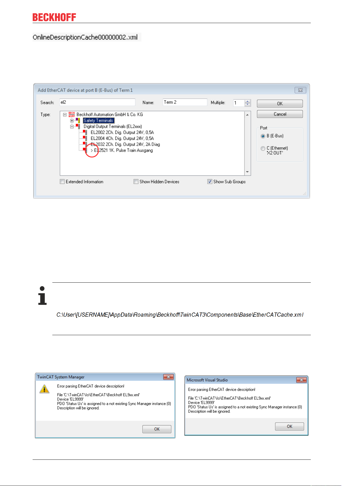
Commissioning
Fig.79: File OnlineDescription.xml created by the System Manager
Is a slave desired to be added manually to the configuration at a later stage, online created slaves are
indicated by a prepended symbol “>” in the selection list (see Figure “Indication of an online recorded ESI of
EL2521 as an example”).
Fig.80: Indication of an online recorded ESI of EL2521 as an example
If such ESI files are used and the manufacturer's files become available later, the file OnlineDescription.xml
should be deleted as follows:
• close all System Manager windows
• restart TwinCAT in Config mode
• delete "OnlineDescription0000...xml"
• restart TwinCAT System Manager
This file should not be visible after this procedure, if necessary press <F5> to update
OnlineDescription for TwinCAT3.x
In addition to the file described above "OnlineDescription0000...xml" , a so called EtherCAT cache
with new discovered devices is created by TwinCAT3.x, e.g. under Windows 7:
(Please note the language settings of the OS!)
You have to delete this file, too.
Faulty ESI file
If an ESI file is faulty and the System Manager is unable to read it, the System Manager brings up an
information window.
Fig.81: Information window for faulty ESI file (left: TwinCAT2; right: TwinCAT3)
EJ9576 77Version: 1.1
Page 78

Commissioning
Reasons may include:
• Structure of the *.xml does not correspond to the associated *.xsd file → check your schematics
• Contents cannot be translated into a device description → contact the file manufacturer
EJ957678 Version: 1.1
Page 79

Commissioning
6.2.3 TwinCAT ESI Updater
For TwinCAT2.11 and higher, the System Manager can search for current Beckhoff ESI files automatically, if
an online connection is available:
Fig.82: Using the ESI Updater (>= TwinCAT2.11)
The call up takes place under:
“Options” → "Update EtherCAT Device Descriptions"
Selection under TwinCAT3:
Fig.83: Using the ESI Updater (TwinCAT3)
The ESI Updater (TwinCAT3) is a convenient option for automatic downloading of ESI data provided by
EtherCAT manufacturers via the Internet into the TwinCAT directory (ESI = EtherCAT slave information).
TwinCAT accesses the central ESI ULR directory list stored at ETG; the entries can then be viewed in the
Updater dialog, although they cannot be changed there.
The call up takes place under:
“TwinCAT“ → „EtherCAT Devices“ → “Update Device Description (via ETG Website)…“.
6.2.4 Distinction between Online and Offline
The distinction between online and offline refers to the presence of the actual I/O environment (drives,
terminals, EJ-modules). If the configuration is to be prepared in advance of the system configuration as a
programming system, e.g. on a laptop, this is only possible in “Offline configuration” mode. In this case all
components have to be entered manually in the configuration, e.g. based on the electrical design.
If the designed control system is already connected to the EtherCAT system and all components are
energised and the infrastructure is ready for operation, the TwinCAT configuration can simply be generated
through “scanning” from the runtime system. This is referred to as online configuration.
In any case, during each startup the EtherCAT master checks whether the slaves it finds match the
configuration. This test can be parameterised in the extended slave settings. Refer to note “Installation of
the latest ESI-XML device description” [}75].
For preparation of a configuration:
• the real EtherCAT hardware (devices, couplers, drives) must be present and installed
• the devices/modules must be connected via EtherCAT cables or in the terminal/ module strand in the
same way as they are intended to be used later
EJ9576 79Version: 1.1
Page 80

Commissioning
• the devices/modules be connected to the power supply and ready for communication
• TwinCAT must be in CONFIG mode on the target system.
The online scan process consists of:
• detecting the EtherCAT device [}85] (Ethernet port at the IPC)
• detecting the connected EtherCAT devices [}86]. This step can be carried out independent of the
preceding step
• troubleshooting [}89]
The scan with existing configuration [}90] can also be carried out for comparison.
6.2.5 OFFLINE configuration creation
Creating the EtherCAT device
Create an EtherCAT device in an empty System Manager window.
Fig.84: Append EtherCAT device (left: TwinCAT2; right: TwinCAT3)
Select type ‘EtherCAT’ for an EtherCAT I/O application with EtherCAT slaves. For the present publisher/
subscriber service in combination with an EL6601/EL6614 terminal select “EtherCAT Automation Protocol
via EL6601”.
Fig.85: Selecting the EtherCAT connection (TwinCAT2.11, TwinCAT3)
Then assign a real Ethernet port to this virtual device in the runtime system.
Fig.86: Selecting the Ethernet port
EJ957680 Version: 1.1
Page 81

Commissioning
This query may appear automatically when the EtherCAT device is created, or the assignment can be set/
modified later in the properties dialog; see Fig. “EtherCAT device properties (TwinCAT2)”.
Fig.87: EtherCAT device properties (TwinCAT2)
TwinCAT 3: the properties of the EtherCAT device can be opened by double click on “Device .. (EtherCAT)”
within the Solution Explorer under “I/O”:
Selecting the Ethernet port
Ethernet ports can only be selected for EtherCAT devices for which the TwinCAT real-time driver is
installed. This has to be done separately for each port. Please refer to the respective installation
page [}69].
Defining EtherCAT slaves
Further devices can be appended by right-clicking on a device in the configuration tree.
Fig.88: Appending EtherCAT devices (left: TwinCAT2; right: TwinCAT3)
The dialog for selecting a new device opens. Only devices for which ESI files are available are displayed.
Only devices are offered for selection that can be appended to the previously selected device. Therefore the
physical layer available for this port is also displayed (Fig. “Selection dialog for new EtherCAT device”, A). In
the case of cable-based Fast-Ethernet physical layer with PHY transfer, then also only cable-based devices
are available, as shown in Fig. “Selection dialog for new EtherCAT device”. If the preceding device has
several free ports (e.g. EK1122 or EK1100), the required port can be selected on the right-hand side (A).
Overview of physical layer
• “Ethernet”: cable-based 100BASE-TX: EK couplers, EP boxes, devices with RJ45/M8/M12 connector
EJ9576 81Version: 1.1
Page 82

Commissioning
• “E-Bus”: LVDS “terminal bus”, “EJ-module”: EL/ES terminals, various modular modules
The search field facilitates finding specific devices (since TwinCAT2.11 or TwinCAT3).
Fig.89: Selection dialog for new EtherCAT device
By default only the name/device type is used as selection criterion. For selecting a specific revision of the
device the revision can be displayed as “Extended Information”.
Fig.90: Display of device revision
In many cases several device revisions were created for historic or functional reasons, e.g. through
technological advancement. For simplification purposes (see Fig. “Selection dialog for new EtherCAT
device”) only the last (i.e. highest) revision and therefore the latest state of production is displayed in the
selection dialog for Beckhoff devices. To show all device revisions available in the system as ESI
descriptions tick the “Show Hidden Devices” check box, see Fig. “Display of previous revisions”.
EJ957682 Version: 1.1
Page 83

Fig.91: Display of previous revisions
Device selection based on revision, compatibility
The ESI description also defines the process image, the communication type between master and
slave/device and the device functions, if applicable. The physical device (firmware, if available) has
to support the communication queries/settings of the master. This is backward compatible, i.e.
newer devices (higher revision) should be supported if the EtherCAT master addresses them as an
older revision. The following compatibility rule of thumb is to be assumed for Beckhoff EtherCAT
Terminals/ Boxes/ EJ-modules:
device revision in the system >= device revision in the configuration
This also enables subsequent replacement of devices without changing the configuration (different
specifications are possible for drives).
Commissioning
Example:
If an EL2521-0025-1018 is specified in the configuration, an EL2521-0025-1018 or higher (-1019, -1020) can
be used in practice.
Fig.92: Name/revision of the terminal
If current ESI descriptions are available in the TwinCAT system, the last revision offered in the selection
dialog matches the Beckhoff state of production. It is recommended to use the last device revision when
creating a new configuration, if current Beckhoff devices are used in the real application. Older revisions
should only be used if older devices from stock are to be used in the application.
In this case the process image of the device is shown in the configuration tree and can be parameterised as
follows: linking with the task, CoE/DC settings, plug-in definition, startup settings, ...
EJ9576 83Version: 1.1
Page 84

Commissioning
Fig.93: EtherCAT terminal in the TwinCAT tree (left: TwinCAT2; right: TwinCAT3)
EJ957684 Version: 1.1
Page 85

Commissioning
6.2.6 ONLINE configuration creation
Detecting/scanning of the EtherCAT device
The online device search can be used if the TwinCAT system is in CONFIG mode. This can be indicated by
a symbol right below in the information bar:
• on TwinCAT2 by a blue display “Config Mode” within the System Manager window: .
• on TwinCAT3 within the user interface of the development environment by a symbol .
TwinCAT can be set into this mode:
• TwinCAT2: by selection of in the Menubar or by “Actions” → “Set/Reset TwinCATtoConfig
Mode…”
• TwinCAT3: by selection of in the Menubar or by „TwinCAT“ → “RestartTwinCAT(ConfigMode)“
Online scanning in Config mode
The online search is not available in RUN mode (production operation). Note the differentiation between TwinCAT programming system and TwinCAT target system.
The TwinCAT2 icon ( ) or TwinCAT3 icon ( ) within the Windows-Taskbar always shows the
TwinCAT mode of the local IPC. Compared to that, the System Manager window of TwinCAT2 or the user
interface of TwinCAT3 indicates the state of the target system.
Fig.94: Differentiation local/target system (left: TwinCAT2; right: TwinCAT3)
Right-clicking on “I/O Devices” in the configuration tree opens the search dialog.
Fig.95: Scan Devices (left: TwinCAT2; right: TwinCAT3)
This scan mode attempts to find not only EtherCAT devices (or Ethernet ports that are usable as such), but
also NOVRAM, fieldbus cards, SMB etc. However, not all devices can be found automatically.
Fig.96: Note for automatic device scan (left: TwinCAT2; right: TwinCAT3)
EJ9576 85Version: 1.1
Page 86

Commissioning
Ethernet ports with installed TwinCAT real-time driver are shown as “RT Ethernet” devices. An EtherCAT
frame is sent to these ports for testing purposes. If the scan agent detects from the response that an
EtherCAT slave is connected, the port is immediately shown as an “EtherCAT Device” .
Fig.97: Detected Ethernet devices
Via respective checkboxes devices can be selected (as illustrated in Fig. “Detected Ethernet devices” e.g.
Device 3 and Device 4 were chosen). After confirmation with “OK” a device scan is suggested for all selected
devices, see Fig.: “Scan query after automatic creation of an EtherCAT device”.
Selecting the Ethernet port
Ethernet ports can only be selected for EtherCAT devices for which the TwinCAT real-time driver is
installed. This has to be done separately for each port. Please refer to the respective installation
page [}69].
Detecting/Scanning the EtherCAT devices
Online scan functionality
During a scan the master queries the identity information of the EtherCAT slaves from the slave
EEPROM. The name and revision are used for determining the type. The respective devices are located in the stored ESI data and integrated in the configuration tree in the default state defined
there.
Fig.98: Example default state
NOTE
Slave scanning in practice in series machine production
The scanning function should be used with care. It is a practical and fast tool for creating an initial configuration as a basis for commissioning. In series machine production or reproduction of the plant, however, the
function should no longer be used for the creation of the configuration, but if necessary for comparison
[}90] with the defined initial configuration.Background: since Beckhoff occasionally increases the revision
version of the delivered products for product maintenance reasons, a configuration can be created by such
a scan which (with an identical machine construction) is identical according to the device list; however, the
respective device revision may differ from the initial configuration.
Example:
Company A builds the prototype of a machine B, which is to be produced in series later on. To do this the
prototype is built, a scan of the IO devices is performed in TwinCAT and the initial configuration ‘B.tsm’ is
created. The EL2521-0025 EtherCAT terminal with the revision 1018 is located somewhere. It is thus built
into the TwinCAT configuration in this way:
EJ957686 Version: 1.1
Page 87

Commissioning
Fig.99: Installing EthetCAT terminal with revision -1018
Likewise, during the prototype test phase, the functions and properties of this terminal are tested by the
programmers/commissioning engineers and used if necessary, i.e. addressed from the PLC ‘B.pro’ or the
NC. (the same applies correspondingly to the TwinCAT3 solution files).
The prototype development is now completed and series production of machine B starts, for which Beckhoff
continues to supply the EL2521-0025-0018. If the commissioning engineers of the series machine production
department always carry out a scan, a B configuration with the identical contents results again for each
machine. Likewise, A might create spare parts stores worldwide for the coming series-produced machines
with EL2521-0025-1018 terminals.
After some time Beckhoff extends the EL2521-0025 by a new feature C. Therefore the FW is changed,
outwardly recognizable by a higher FW version and a new revision -1019. Nevertheless the new device
naturally supports functions and interfaces of the predecessor version(s); an adaptation of ‘B.tsm’ or even
‘B.pro’ is therefore unnecessary. The series-produced machines can continue to be built with ‘B.tsm’ and
‘B.pro’; it makes sense to perform a comparative scan [}90] against the initial configuration ‘B.tsm’ in order
to check the built machine.
However, if the series machine production department now doesn’t use ‘B.tsm’, but instead carries out a
scan to create the productive configuration, the revision -1019 is automatically detected and built into the
configuration:
Fig.100: Detection of EtherCAT terminal with revision -1019
This is usually not noticed by the commissioning engineers. TwinCAT cannot signal anything either, since
virtually a new configuration is created. According to the compatibility rule, however, this means that no
EL2521-0025-1018 should be built into this machine as a spare part (even if this nevertheless works in the
vast majority of cases).
In addition, it could be the case that, due to the development accompanying production in company A, the
new feature C of the EL2521-0025-1019 (for example, an improved analog filter or an additional process
data for the diagnosis) is discovered and used without in-house consultation. The previous stock of spare
part devices are then no longer to be used for the new configuration ‘B2.tsm’ created in this way.Þ if series
machine production is established, the scan should only be performed for informative purposes for
comparison with a defined initial configuration. Changes are to be made with care!
If an EtherCAT device was created in the configuration (manually or through a scan), the I/O field can be
scanned for devices/slaves.
Fig.101: Scan query after automatic creation of an EtherCAT device (left: TwinCAT2; right: TwinCAT3)
EJ9576 87Version: 1.1
Page 88

Commissioning
Fig.102: Manual triggering of a device scan on a specified EtherCAT device (left: TwinCAT2; right:
TwinCAT3)
In the System Manager (TwinCAT2) or the User Interface (TwinCAT3) the scan process can be monitored
via the progress bar at the bottom in the status bar.
Fig.103: Scan progressexemplary by TwinCAT2
The configuration is established and can then be switched to online state (OPERATIONAL).
Fig.104: Config/FreeRun query (left: TwinCAT2; right: TwinCAT3)
In Config/FreeRun mode the System Manager display alternates between blue and red, and the EtherCAT
device continues to operate with the idling cycle time of 4 ms (default setting), even without active task (NC,
PLC).
Fig.105: Displaying of “Free Run” and “Config Mode” toggling right below in the status bar
Fig.106: TwinCAT can also be switched to this state by using a button (left: TwinCAT2; right: TwinCAT3)
The EtherCAT system should then be in a functional cyclic state, as shown in Fig. “Online display example”.
EJ957688 Version: 1.1
Page 89

Commissioning
Fig.107: Online display example
Please note:
• all slaves should be in OP state
• the EtherCAT master should be in “Actual State” OP
• “frames/sec” should match the cycle time taking into account the sent number of frames
• no excessive “LostFrames” or CRC errors should occur
The configuration is now complete. It can be modified as described under manual procedure [}80].
Troubleshooting
Various effects may occur during scanning.
• An unknown device is detected, i.e. an EtherCAT slave for which no ESI XML description is available.
In this case the System Manager offers to read any ESI that may be stored in the device. This case is
described in the chapter "Notes regarding ESI device description".
• Device are not detected properly
Possible reasons include:
- faulty data links, resulting in data loss during the scan
- slave has invalid device description
The connections and devices should be checked in a targeted manner, e.g. via the emergency scan.
Then re-run the scan.
Fig.108: Faulty identification
In the System Manager such devices may be set up as EK0000 or unknown devices. Operation is not
possible or meaningful.
EJ9576 89Version: 1.1
Page 90

Commissioning
Scan over existing Configuration
NOTE
Change of the configuration after comparison
With this scan (TwinCAT2.11 or 3.1) only the device properties vendor (manufacturer), device name and
revision are compared at present! A ‘ChangeTo’ or ‘Copy’ should only be carried out with care, taking into
consideration the Beckhoff IO compatibility rule (see above). The device configuration is then replaced by
the revision found; this can affect the supported process data and functions.
If a scan is initiated for an existing configuration, the actual I/O environment may match the configuration
exactly or it may differ. This enables the configuration to be compared.
Fig.109: Identical configuration (left: TwinCAT2; right: TwinCAT3)
If differences are detected, they are shown in the correction dialog, so that the user can modify the
configuration as required.
Fig.110: Correction dialog
It is advisable to tick the “Extended Information” check box to reveal differences in the revision.
EJ957690 Version: 1.1
Page 91

Commissioning
Colour Explanation
green This EtherCAT slave matches the entry on the other side. Both type and revision match.
blue This EtherCAT slave is present on the other side, but in a different revision. This other
revision can have other default values for the process data as well as other/additional
functions.
If the found revision is higher than the configured revision, the slave may be used provided
compatibility issues are taken into account.
If the found revision is lower than the configured revision, it is likely that the slave cannot be
used. The found device may not support all functions that the master expects based on the
higher revision number.
light blue This EtherCAT slave is ignored (“Ignore” button)
red • This EtherCAT slave is not present on the other side.
• It is present, but in a different revision, which also differs in its properties from the one
specified.
The compatibility principle then also applies here: if the found revision is higher than the
configured revision, use is possible provided compatibility issues are taken into account,
since the successor devices should support the functions of the predecessor devices.
If the found revision is lower than the configured revision, it is likely that the slave cannot
be used. The found device may not support all functions that the master expects based on
the higher revision number.
Device selection based on revision, compatibility
The ESI description also defines the process image, the communication type between master and
slave/device and the device functions, if applicable. The physical device (firmware, if available) has
to support the communication queries/settings of the master. This is backward compatible, i.e.
newer devices (higher revision) should be supported if the EtherCAT master addresses them as an
older revision. The following compatibility rule of thumb is to be assumed for Beckhoff EtherCAT
Terminals/ Boxes/ EJ-modules:
device revision in the system >= device revision in the configuration
This also enables subsequent replacement of devices without changing the configuration (different
specifications are possible for drives).
Example:
If an EL2521-0025-1018 is specified in the configuration, an EL2521-0025-1018 or higher (-1019, -1020) can
be used in practice.
Fig.111: Name/revision of the terminal
If current ESI descriptions are available in the TwinCAT system, the last revision offered in the selection
dialog matches the Beckhoff state of production. It is recommended to use the last device revision when
creating a new configuration, if current Beckhoff devices are used in the real application. Older revisions
should only be used if older devices from stock are to be used in the application.
In this case the process image of the device is shown in the configuration tree and can be parameterised as
follows: linking with the task, CoE/DC settings, plug-in definition, startup settings, ...
EJ9576 91Version: 1.1
Page 92

Commissioning
Fig.112: Correction dialog with modifications
Once all modifications have been saved or accepted, click “OK” to transfer them to the real *.tsm
configuration.
Change to Compatible Type
TwinCAT offers a function “Change to Compatible Type…” for the exchange of a device whilst retaining the
links in the task.
Fig.113: Dialog “Change to Compatible Type…” (left: TwinCAT2; right: TwinCAT3)
This function is preferably to be used on AX5000 devices.
Change to Alternative Type
The TwinCAT System Manager offers a function for the exchange of a device: Change to Alternative Type
Fig.114: TwinCAT2 Dialog Change to Alternative Type
EJ957692 Version: 1.1
Page 93

Commissioning
If called, the System Manager searches in the procured device ESI (in this example: EL1202-0000) for
details of compatible devices contained there. The configuration is changed and the ESI-EEPROM is
overwritten at the same time – therefore this process is possible only in the online state (ConfigMode).
6.2.7 EtherCAT subscriber configuration
In the left-hand window of the TwinCAT2 System Manager or the Solution Explorer of the TwinCAT3
Development Environment respectively, click on the element of the terminal within the tree you wish to
configure (in the example: EL3751 Terminal 3).
Fig.115: Branch element as terminal EL3751
In the right-hand window of the TwinCAT System manager (TwinCAT2) or the Development Environment
(TwinCAT3), various tabs are now available for configuring the terminal. And yet the dimension of
complexity of a subscriber determines which tabs are provided. Thus as illustrated in the example above the
terminal EL3751 provides many setup options and also a respective number of tabs are available. On the
contrary by the terminal EL1004 for example the tabs "General", "EtherCAT", "Process Data" and “Online“
are available only. Several terminals, as for instance the EL6695 provide special functions by a tab with its
own terminal name, so “EL6695” in this case. A specific tab “Settings” by terminals with a wide range of
setup options will be provided also (e.g. EL3751).
„General“ tab
Fig.116: “General” tab
Name Name of the EtherCAT device
Id Number of the EtherCAT device
Type EtherCAT device type
Comment Here you can add a comment (e.g. regarding the
system).
Disabled Here you can deactivate the EtherCAT device.
Create symbols Access to this EtherCAT slave via ADS is only
available if this control box is activated.
EJ9576 93Version: 1.1
Page 94

Commissioning
„EtherCAT“ tab
Fig.117: „EtherCAT“ tab
Type EtherCAT device type
Product/Revision Product and revision number of the EtherCAT device
Auto Inc Addr. Auto increment address of the EtherCAT device. The
auto increment address can be used for addressing
each EtherCAT device in the communication ring
through its physical position. Auto increment
addressing is used during the start-up phase when
the EtherCAT master allocates addresses to the
EtherCAT devices. With auto increment addressing
the first EtherCAT slave in the ring has the address
0000
decremented by 1 (FFFF
. For each further slave the address is
hex
, FFFE
hex
hex
etc.).
EtherCAT Addr. Fixed address of an EtherCAT slave. This address is
allocated by the EtherCAT master during the start-up
phase. Tick the control box to the left of the input field
in order to modify the default value.
Previous Port Name and port of the EtherCAT device to which this
device is connected. If it is possible to connect this
device with another one without changing the order of
the EtherCAT devices in the communication ring,
then this combination field is activated and the
EtherCAT device to which this device is to be
connected can be selected.
Advanced Settings This button opens the dialogs for advanced settings.
The link at the bottom of the tab points to the product page for this EtherCAT device on the web.
“Process Data” tab
Indicates the configuration of the process data. The input and output data of the EtherCAT slave are
represented as CANopen process data objects (Process Data Objects, PDOs). The user can select a PDO
via PDO assignment and modify the content of the individual PDO via this dialog, if the EtherCAT slave
supports this function.
EJ957694 Version: 1.1
Page 95

Fig.118: “Process Data” tab
Commissioning
The process data (PDOs) transferred by an EtherCAT slave during each cycle are user data which the
application expects to be updated cyclically or which are sent to the slave. To this end the EtherCAT master
(Beckhoff TwinCAT) parameterizes each EtherCAT slave during the start-up phase to define which process
data (size in bits/bytes, source location, transmission type) it wants to transfer to or from this slave. Incorrect
configuration can prevent successful start-up of the slave.
For Beckhoff EtherCAT EL, ES, EM, EJ and EP slaves the following applies in general:
• The input/output process data supported by the device are defined by the manufacturer in the ESI/XML
description. The TwinCAT EtherCAT Master uses the ESI description to configure the slave correctly.
• The process data can be modified in the system manager. See the device documentation.
Examples of modifications include: mask out a channel, displaying additional cyclic information, 16-bit
display instead of 8-bit data size, etc.
• In so-called “intelligent” EtherCAT devices the process data information is also stored in the CoE
directory. Any changes in the CoE directory that lead to different PDO settings prevent successful
startup of the slave. It is not advisable to deviate from the designated process data, because the
device firmware (if available) is adapted to these PDO combinations.
If the device documentation allows modification of process data, proceed as follows (see Figure “Configuring
the process data”).
• A: select the device to configure
• B: in the “Process Data” tab select Input or Output under SyncManager (C)
• D: the PDOs can be selected or deselected
• H: the new process data are visible as linkable variables in the system manager
The new process data are active once the configuration has been activated and TwinCAT has been
restarted (or the EtherCAT master has been restarted)
• E: if a slave supports this, Input and Output PDO can be modified simultaneously by selecting a socalled PDO record (“predefined PDO settings”).
EJ9576 95Version: 1.1
Page 96

Commissioning
Fig.119: Configuring the process data
Manual modification of the process data
According to the ESI description, a PDO can be identified as “fixed” with the flag “F” in the PDO
overview (Fig. “Configuring the process data”, J). The configuration of such PDOs cannot be
changed, even if TwinCAT offers the associated dialog (“Edit”). In particular, CoE content cannot be
displayed as cyclic process data. This generally also applies in cases where a device supports
download of the PDO configuration, “G”. In case of incorrect configuration the EtherCAT slave usually refuses to start and change to OP state. The System Manager displays an “invalid SM cfg” logger message: This error message (“invalid SM IN cfg” or “invalid SM OUT cfg”) also indicates the
reason for the failed start.
A detailed description [}101] can be found at the end of this section.
„Startup“ tab
The Startup tab is displayed if the EtherCAT slave has a mailbox and supports the CANopen over EtherCAT
(CoE) or Servo drive over EtherCAT protocol. This tab indicates which download requests are sent to the
mailbox during startup. It is also possible to add new mailbox requests to the list display. The download
requests are sent to the slave in the same order as they are shown in the list.
EJ957696 Version: 1.1
Page 97

Fig.120: „Startup“ tab
Column Description
Transition Transition to which the request is sent. This can either be
• the transition from pre-operational to safe-operational (PS), or
• the transition from safe-operational to operational (SO).
If the transition is enclosed in "<>" (e.g. <PS>), the mailbox request is fixed and cannot be
modified or deleted by the user.
Protocol Type of mailbox protocol
Index Index of the object
Data Date on which this object is to be downloaded.
Comment Description of the request to be sent to the mailbox
Commissioning
Move Up This button moves the selected request up by one
position in the list.
Move Down This button moves the selected request down by one
position in the list.
New This button adds a new mailbox download request to
be sent during startup.
Delete This button deletes the selected entry.
Edit This button edits an existing request.
“CoE – Online” tab
The additional CoE - Online tab is displayed if the EtherCAT slave supports the CANopen over EtherCAT
(CoE) protocol. This dialog lists the content of the object list of the slave (SDO upload) and enables the user
to modify the content of an object from this list. Details for the objects of the individual EtherCAT devices can
be found in the device-specific object descriptions.
EJ9576 97Version: 1.1
Page 98

Commissioning
Fig.121: “CoE – Online” tab
Object list display
Column Description
Index Index and sub-index of the object
Name Name of the object
Flags RW The object can be read, and data can be written to the object (read/write)
RO The object can be read, but no data can be written to the object (read only)
P An additional P identifies the object as a process data object.
Value Value of the object
Update List The Update list button updates all objects in the displayed list
Auto Update If this check box is selected, the content of the objects is updated automatically.
Advanced The Advanced button opens the Advanced Settings dialog. Here you can specify
which objects are displayed in the list.
EJ957698 Version: 1.1
Page 99

Commissioning
Fig.122: Dialog “Advanced settings”
Online - via SDO Information If this option button is selected, the list of the objects included in the object
list of the slave is uploaded from the slave via SDO information. The list
below can be used to specify which object types are to be uploaded.
Offline - via EDS File If this option button is selected, the list of the objects included in the object
list is read from an EDS file provided by the user.
„Online“ tab
Fig.123: „Online“ tab
EJ9576 99Version: 1.1
Page 100

Commissioning
State Machine
Init This button attempts to set the EtherCAT device to the Init state.
Pre-Op This button attempts to set the EtherCAT device to the pre-operational state.
Op This button attempts to set the EtherCAT device to the operational state.
Bootstrap This button attempts to set the EtherCAT device to the Bootstrap state.
Safe-Op This button attempts to set the EtherCAT device to the safe-operational state.
Clear Error This button attempts to delete the fault display. If an EtherCAT slave fails during
change of state it sets an error flag.
Example: An EtherCAT slave is in PREOP state (pre-operational). The master now
requests the SAFEOP state (safe-operational). If the slave fails during change of state
it sets the error flag. The current state is now displayed as ERR PREOP. When the
Clear Error button is pressed the error flag is cleared, and the current state is
displayed as PREOP again.
Current State Indicates the current state of the EtherCAT device.
Requested State Indicates the state requested for the EtherCAT device.
DLL Status
Indicates the DLL status (data link layer status) of the individual ports of the EtherCAT slave. The DLL status
can have four different states:
Status Description
No Carrier / Open No carrier signal is available at the port, but the port is open.
No Carrier / Closed No carrier signal is available at the port, and the port is closed.
Carrier / Open A carrier signal is available at the port, and the port is open.
Carrier / Closed A carrier signal is available at the port, but the port is closed.
File Access over EtherCAT
Download With this button a file can be written to the EtherCAT device.
Upload With this button a file can be read from the EtherCAT device.
"DC" tab (Distributed Clocks)
Fig.124: "DC" tab (Distributed Clocks)
Operation Mode Options (optional):
• FreeRun
• SM-Synchron
• DC-Synchron (Input based)
• DC-Synchron
Advanced Settings… Advanced settings for readjustment of the real time determinant TwinCAT-
clock
Detailed information to Distributed Clocks are specified on http://infosys.beckhoff.com:
EJ9576100 Version: 1.1
 Loading...