

Page 1

WARNING
!
Incorrect installation, adjustment, or misuse of this burner could result in death, severe
personal injury, or substantial property damage.
Potential for Fire, Smoke and Asphyxiation Hazards
To the Homeowner or Equipment
Owner:
Please read and carefully follow all instructions
y
provided in this manual regarding your responsibilities
in caring for your heating equipment.
Contact a professional, qualifi ed service agency for
y
installation, start-up or service work.
Save this manual for future reference.
y
6104 BCF3 R02 Page 1
To the Professional, Qualifi ed Installer
or Service Agency:
Please read and carefully follow all instructions provided
y
in this manual before installing, starting, or servicing this
burner or heating system.
The Installation must be made in accordance with all state
y
and local codes having jurisdiction.
Page 2

Table of Contents
Before you begin .....................................................................................................................................2-4
To the Owner .......................................................................................................................................................3
Agency approvals ................................................................................................................................................3
Hazard Defi nitions ...................................................................................................................... .........................3
Specifi cations ......................................................................................................................................................3
Owner’s Responsibility ........................................................................................................................................4
Professional Installer/Service Agency Responsibility ..........................................................................................4
Pre-installation checklist......................................................................................................................4-6
Combustion air supply .........................................................................................................................................5
Clearances .........................................................................................................................................................5
Fuel supply .........................................................................................................................................................5
Nozzle pressure ..................................................................................................................................................5
Vent system .........................................................................................................................................................5
Electrical supply ..................................................................................................................................................5
Verify burner components ...................................................................................................................................5
Verify fi ring rate ...................................................................................................................................................6
Verify air tube ......................................................................................................................................................6
Mount the burner .....................................................................................................................................7-9
Mount fl anges on air tubes ..................................................................................................................................7
Mount air tube to burner ......................................................................................................................................7
Install Nozzle .......................................................................................................................................................7
Check Electrodes ................................................................................................................................................7
Install Nozzle Line Assembly ...............................................................................................................................7
Set Dimension Z ..................................................................................................................................................8
Insert Burner ........................................................................................................................................................8
Fuel Unit By-pass Plug ........................................................................................................................................8
Oil Supply/Return Lines .......................................................................................................................................8
Burner Fuel Flow .................................................................................................................................................9
Wire the burner .............................................................................................................................................9
Prepare the burner for start-up .....................................................................................................10-11
Start-up checklist ...............................................................................................................................................11
Z Dimension ......................................................................................................................................................11
Initial head position ............................................................................................................................................11
Initial air settings ................................................................................................................................................11
Set appliance limit controls ................................................................................................................................11
Prepare the fuel unit for air venting ...................................................................................................................11
Start the burner .........................................................................................................................................12
Starting the burner and venting air ...................................................................................................................12
Resetting from restricted lockout .......................................................................................................................12
Disable function .................................................................................................................................................12
CAD Cell resistance check ................................................................................................................................12
Set air adjusting plate ........................................................................................................................................12
Maintenance and Service ..................................................................................................13
Annual Service ..................................................................................................................................................13
Monthly maintenance ........................................................................................................................................14
Replacement Parts...................................................................................................................................15
Warranty ................................................................................................................................... Back Cover
Page 2 6104 BCF3 R02
Page 3
Before you begin . . .
The following resources will give you addional information for your installation. We suggest that you consult
these resources whenever possible. Pay particular attention to the appliance manufacturer’s instructions.
Appliance manufacturer’s instructions -Always follow the appliance manufacturer’s instructions for burner installation, equipment and set-up.
1–800–OIL–BURN - Beckett’s technical services hot-line.
www.beckettcorp.com - Beckett’s website.
To the Owner:
Thank you for purchasing a Beckett burner for
use with your heating appliance. Please pay attention
to the Safety Warnings contained within this instruction manual. Keep this manual for your records and
provide it to your qualifi ed service agency for use in
professionally setting up and maintaining your oil
burner.
Your Beckett burner will provide years of effi cient
operation if it is professionally installed and maintained by a qualifi ed service technician. If at any time
the burner does not appear to be operating properly,
immediately contact your qualifi ed service agency
for consultation.
We recommend annual inspection/service of your
oil heating system by a qualifi ed service agency.
Hazard defi nitions
Indicates an imminently
hazardous situation,
which, if not avoided, will result in death,
serious injury, or property damage.
Within the boundaries of the hazard warning, there will
be information presented describing consequences if the
warning is not heeded and instructions on how to avoid
the hazard.
Agency approvals
UL listed to comply with ANSI/UL296 and certifi ed to
CSA B140.0.
Accepted by N.Y.C. M.E.A.
Other approvals may be available and must be specifi ed at
time of order.
Specifi cations
Fuels
U.S. #1 or #2 Fuel Oil only
(ASTM D396)
Canada #1 Stove Oil or #2
Furnace Oil only
Indicates a potentially
hazardous situation,
which, if not avoided, could result in death,
severe personal injury, and/or substantial
property damage.
Indicates a potentially
hazardous situation,
which, if not avoided, may result in personal injury or property damage.
NOTICE
Firing range 1.65 to 3.75 GPH
Motor 1/7 HP 3450 RPM
120/60 hz standard
1.7 amps @ 120 VAC
Optional voltages:
(60 hz or 50 hz) –
Ignition Trans. 120V/12,000V
Housing Cast aluminum
Fuel unit 100 - 200 PSIG
Oil nozzle 45° - 70° solid
Shipping wt. 25 lbs.
Intended to bring special attention to information,
but not related to personal injury or property
damage.
6104 BCF3 R02 Page 3
Page 4
Owner’s Responsibility:
NOTICE
Follow These
Instructions Exactly
Failure to follow these instructions,
misuse, or incorrect adjustment of
the burner could lead to equipment
malfunction and result in asphyxiation, explosion or fi re.
Contact a professional, qualifi ed service agency for the
installation, adjustment and service of your oil burning
system. Thereafter, have your equipment adjusted and
inspected at least annually to ensure reliable operation.
This work requires technical training, trade experience,
licensing or certifi cation in some states and the proper
use of special combustion test instruments.
Please carefully read and comply with the following
instructions:
y
Never store or use gasoline or other fl ammable liquids
or vapors near this burner or appliance.
y
Never attempt to burn garbage or refuse in this appliance.
y
Never attempt to light the burner by throwing burning
material into the appliance.
y
Never attempt to burn any fuel not specifi ed and ap-
proved for use in this burner.
y
Never restrict the air inlet openings to the burner or the
combustion air ventilation openings in the room.
Professional Installer/Service Agency
Responsibility:
High altitude installations — Accepted industry practice
requires no derate of burner capacity up to 2,000 feet above
sea level. For altitudes higher than 2,000 feet, derate burner
capacity 2% for each 1000 feet above sea level.
Pre-installation check-
list
Protect Against Stray
Light Lockout
Failure to follow these instructions could cause
loss of burner operation resulting in no heat, an
unplanned process interruption, work stoppage
and the potential for frozen plumbing or other
cold weather property damage.
The control must detect a dark, no-fl ame condition in
y
order to start the burner or it will hold in the stray light
lockout mode.
y
Shield the burner from direct exposure to intense
light.
Protect Against Dust and
Moisture
Wet, dusty environments could lead to blocked
air passages, corrosion damage to components,
impaired combustion performance and result in
asphyxiation, explosion or fi re.
Follow These
Instructions Exactly
Failure to follow these instructions
could lead to equipment malfunction and result in asphyxiation,
explosion or fi re.
Please read all instructions before proceeding. Follow
y
all instructions completely.
y
This equipment must be installed, adjusted and started
by a qualifi ed service agency that is experienced with
all applicable codes and ordinances and responsible for
the installation and commission of the equipment.
y
The installation must comply with all local codes and
ordinances having jurisdiction and the latest editions of
the NFPA 31 and CSA-B139 & B140 in Canada.
NOTICE
50 Hz motors — The burner ratings, air settings and nozzle
ratings are based on standard 60 hz motors (at 3450 rpm).
Derate all ratings 20% when using 50 hz motors. Consult
factory for specifi c application data.
This burner is designed for clean, dry installations.
y
y
Electrical controls are not protected against rain or
sprayed water.
y
Keep the installation clear of dust, dirt, corrosive vapors, and moisture.
y
Protective covers and more frequent maintenance may
be required.
Adequate Combustion
and Ventilation Air
Supply Required
Failure to provide adequate air supply could se-
riously affect the burner performance and result
in damage to the equipment, asphyxiation, explosion or fi re hazards.
The burner cannot properly burn the fuel if it is not
y
supplied with a reliable combustion air source.
y
Follow the guidelines in the latest editions of the NFP A
31 and CSA-B139 regarding providing adequate air for
combustion and ventilation.
Page 4 6104 BCF3 R02
Page 5
Combustion air supply
The burner requires combustion air and ventilation air for
y
reliable operation. Assure that the building and/or combustion air openings comply with National Fire Protection Standard for Oil-Burning Equipment, NFPA 31. For
appliance/burner units in confi ned spaces, the room must
have an air opening near the top of the room plus one near
the fl oor, each with a free area at least one square inch
per 1,000 Btu/hr input of all fuel burning equipment in
the room. For other conditions, refer to NFPA 31 (CSA
B1139-M91 in Canada).
If there is a risk of the space being under negative pres-
y
sure or of exhaust fans or other devices depleting available
air for combustion and ventilation, the appliance/burner
should be installed in an isolated room provided with outside combustion air.
Clearances
With the burner installed in the appliance, there must be
y
adequate space in front of and on the sides of the burner
to allow access and operation. Verify that the clearance
dimensions comply with all local codes and with the appliance manufacturer’s recommendations.
Fuel supply
Nozzle pressure
Correct Nozzle and Flow
Rate Required
Incorrect nozzles and fl ow rates
could result in impaired combustion,
under-fi ring, over-fi ring, sooting,
puff-back of hot gases, smoke and
potential fi re or asphyxiation haz-
ards.
Use only nozzles having the brand, fl ow rate (gph), spray
angle and pattern specifi ed by the appliance manufac-
turer.
Follow the appliance manufacturer’s specifi cations for
the required pump outlet pressure for the nozzle, since
this affects the fl ow rate.
Nozzle manufacturers calibrate nozzle fl ow rates at
y
100 psig.
y
This burner utilizes pressures higher than 100 psig, so
the actual nozzle fl ow rate will be greater than the gph
stamped on the nozzle body. (Example: A 2.00 gph
nozzle at 150 psig = 2.45 gph.
y
For typical nozzle fl ow rates at various pressures
see accompanying chart.
The fuel supply piping and tank must provide #1 or #2 fuel
y
oil at pressure or vacuum conditions suitable for the fuel
unit (oil pump) on the burner. Refer to fuel unit literature
in the literature envelope in the burner carton to verify allowable suction pressure.
Oil Supply Pressure
Control Required
Damage to the pump, fi lter or other compo-
nent seals could cause possible oil leakage
and potential fi re hazard.
The oil supply inlet pressure to the fuel unit cannot
y
exceed 3 psig.
y
Ensure that a pressure-limiting device is installed in
accordance with the latest edition of the NFPA 31.
If fuel supply is level with or higher than fuel unit —
When the fuel unit is not required to lift the oil, the instal-
y
lation is usually suitable for either a one-pipe or two-pipe
oil system. The oil pressure at the inlet of the fuel unit
must not exceed 3 psig.
Refer to the Mount the Burner Section of this manual for
y
one-pipe or two-pipe fuel supply installation instructions.
If fuel supply is below the fuel unit —
The fuel unit nozzle port pressure is factory set at 140
y
psig. Some original equipment manufacturer burner applications may call for a lower pressure to obtain a required
fi ring rate. Do not change this pressure unless directed to
do so by the appliance manufacturer.
Vent system
The fl ue gas venting system must be in good condition and
y
must comply with all applicable codes.
Electrical supply
Verify that the power connections available are correct for
y
the burner. All power must be supplied through fused disconnect switches.
Verify burner components —
Burner, Model CF375
y
Air tube assembly
y
Mounting fl ange kit
y
Oil nozzle, per Table 1 — Only 45° to 70° solid pattern
y
nozzles are recommended unless otherwise specifi ed by
appliance manufacturer. (See specifi c appliance recom-
mendation sheet or refer to OEM Spec Guide). Find the
required fi ring rate in the 150 psig column (factory-set fuel
unit pressure). Select the corresponding nozzle from column 1 (Rated gph @ 100 psig).
Use a two-pipe oil system when the fuel unit must lift the
y
oil more than 8 feet if burner is equipped with a B fuel
unit. The return line provided by the two-pipe system is
needed to purge the air from the fuel lines and minimize
the likelihood of air-related problems during operation.
6104 BCF3 R02 Page 5
Page 6
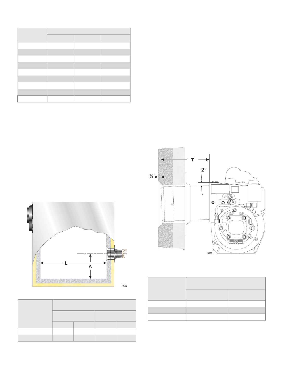
Table 1 - Nozzle Capacities
Verify air tube
Rated gph @
100 psig
1.35 1.51 1.60 1.65
1.50 1.68 1.77 1.84
1.65 1.84 1.95 2.02
1.75 1.96 2.07 2.14
2.00 2.24 2.37 2.45
2.25 2.52 2.66 2.76
2.50 2.80 2.96 3.06
2.75 3.07 3.25 3.37
3.00 3.35 3.55 3.67
Verify fi ring rate
Refer to appliance manufacturer’s instructions (if
y
Pressure - pounds per square inch
125 140 150
available) for fi ring rate and nozzle selection. Otherwise,
the maximum recommended fi ring rate for the burner
depends on the length of the fi ring chamber and the
distance from the burner center to the chamber fl oor.
Verify that the chamber dimensions are at least as large
as the minimum values given in Figure 1. If the appliance
dimensions are smaller than recommended, reduce the
fi ring rate accordingly.
The information in this section may be disregarded if the
y
air tube is supplied by the appliance manufacturer.
Two tube arrangements are available –
y
Tube A — 1.65 to 2.00 GPH
Tube B — 2.00 to 3.75 GPH
Maximum fi ring capacity depends on the fi rebox pressure.
y
Use Table 2 to verify the correct air tube type for the fi r-
ing rate required. Use Tube B only when Tube A cannot
provide the fi ring rate required.
See Figure 2 to verify the correct air tube length and air
y
tube combination code.
Figure 2 - Air Tube Mounting Dimensions
X
Figure 1. Min. Combustion Chamber Dimensions
Minimum Dimensions
Firing Rate
1.65 to 2.00 gph
2.00 to 3.75 gph
(refractory-lined) (wet-base boilers)
ALAL
5.5” 12.0” 5.5” 12.0”
6.0” 15.0” 6.0” 20.0”
X Install burner with 2
Air Tube
Length
(Dimension T)
05.75” CF56KY CF56KZ
10.00” CF100KY CF100KZ
14.00” CF140KY CF140KZ
o
pitch as shown.
A.T.C. Codes
(A.T.C. = Air Tube Combination)
Tube A Tube B
Page 6 6104 BCF3 R02
Page 7
Mount the burner
Protect the Air Tube From
Overheating
Overheating could cause damage to the air
tube and other combustion components leading to equipment malfunction and impaired
combustion performance.
The end of the air tube must not extend into the com-
y
bustion chamber unprotected unless it has been factory-tested and specifi ed by the appliance manufacturer.
y
Position the end of the air tube ¼” back from fl ush with
the refractory inside entry wall to prevent damage from
overheating.
Mount fl ange(s) on air tube
This section does not apply to burners with welded fl ang-
y
es.
Do not install air tube on burner.
y
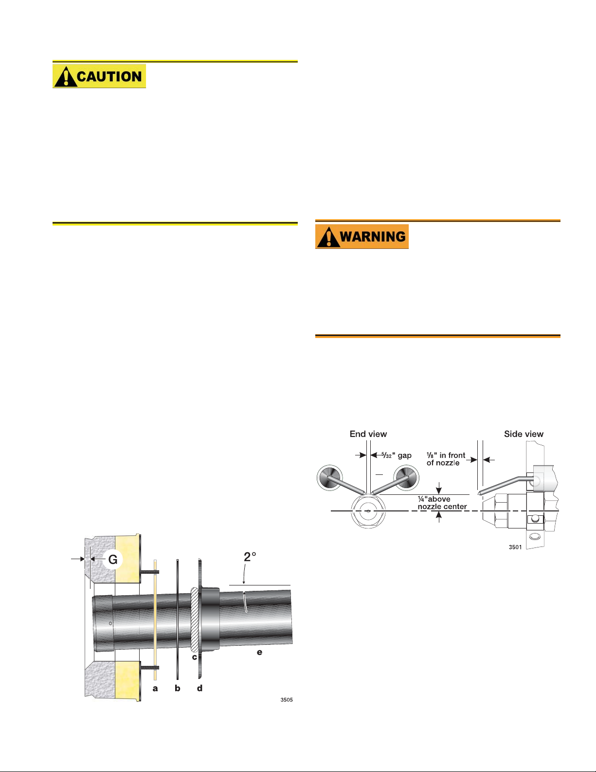
For non-pressure fi ring fl ange, refer to Figure 3: Install
y
gasket (item a) and fl ange (item d). Ignore the next
paragraph.
For pressure-fi ring fl ange, refer to Figure 3: Slide gasket
y
(item a) onto the air tube, making sure the top of the air
tube is up. Pre-drill holes in the pressure fi ring plate (item
b) to match the appliance studs. Slide the pressure fi ring
plate (item b) and fl ange (item d) onto the air tube as
shown. Wrap ceramic fi ber rope (item c) around the air
tube and press tightly into the inside diameter of the fl ange
(item d).
Slide the air tube (item e) into position in the appliance
y
front. Tighten the fl ange-mounting-stud nuts. Set the
insertion of the air tube so dimension G is ¼” nominal.
Pitch the air tube at 2° from horizontal as shown and secure
y
the fl ange to the air tube. See Figure 2.
Mount air tube to burner
Insert the air tube into the burner housing. Carefully align
y
the the four screw holes.
Attach the air tube to the burner using the four provided
y
screws.
Install nozzle
y
Install the oil nozzle in the nozzle adapter. Use a 3/4”
open-end wrench to steady the nozzle adapter and a 5/8”
open-end wrench to turn the nozzle. Tighten securely but
do not over-tighten.
Check electrode settings
Maintain Electrode
Specifi cations
Failure to properly maintain these specifi cations
could cause ignition malfunction, puff-back of
hot gases, heavy smoke, asphyxiation, explosion and fi re hazards.
Adjust the electrode gap and position in relation to the
y
nozzle to the specifi cations shown in Figure 4.
Check, and adjust if necessary, the critical dimensions
y
shown in Figure 4. Verify that the oil tube assembly and
electrodes are in good condition, with no cracks or damage.
Figure 4 - Nozzle and nozzle line assembly
Figure 3 - Mount fl ange(s) on air tube
Install nozzle line assembly
Insert the nozzle line assembly into the burner air tube.
y
Reference Figure 5.
Slide the secondary adjusting plate (Figure 6, item f) com-
y
pletely to the left on the indicator adjusting plate (item e).
Finger tighten acorn nut (item c) to secure the two plates
together. Slide both plates completely to the right (Indicator Plate will read 0). Tighten fastener (item d).
Install the spline nut on the end of the nozzle line, leaving
y
the nut loosely placed so the plates can be moved.
6104 BCF3 R02 Page 7
Page 8
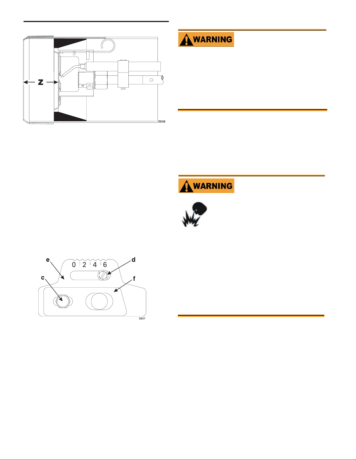
Figure 5 - Nozzle line assembly in burner
1-1/2”
Set dimension Z
Loosen fastener c in Figure 6. Slide the nozzle line and
y
plate assembly until dimension Z in Figure 5 is 1-1/2”
±1/16”. When dimension Z (from end of air tube to fl at
area of front face of head) is correctly set, tighten acorn
nut c.
Attach the oil line from the oil valve to the nozzle line end.
y
Tighten securely.
Before proceeding, check dimension Z once again. Loosen
y
acorn nut c if necessary to reposition the nozzle line. Once
dimension Z is set, do not loosen the acorn nut c again.
Note that for the setting of fastener d, refer to Initial Head
Position procedure on Page 10.
Figure 6 - Adjusting plate assy.
Fuel unit by-pass plug
Do Not Install By-pass
Plug with 1-Pipe System
Failure to comply could cause immediate pump
seal failure, pressurized oil leakage and the potential for a fi re and injury hazard.
The burner is shipped without the by-pass plug in-
y
stalled.
Intall the by-pass plug in two-pipe oil supply systems
y
ONLY.
The CF375 burner is shipped without the by-pass plug
y
installed in the fuel line.
y
The by-pass plug must NOT be installed when using
with a one-pipe oil system.
y
The by-pass plug MUST be installed when using a
two-pipe oil system
Oil supply/return lines
.
Install Oil Supply To
Specifi cations
Failure to properly install the oil
supply system could cause oil
leakage, equipment malfunction,
puff-back of hot gases, heavy
smoke, asphyxiation, explosion and
fi re hazards.
Carefully install the oil supply lines, fi ttings and com-
y
ponents using the guidelines provided in this section.
y
The oil supply must comply with the latest edition
of NFPA 31 (Canada CSA B139) and all applicable
codes.
y
Do NOT install valves in return lines.
y
If the oil supply inlet pressure to the pump exceeds 3
psig or for gravity feed systems, install an oil safety or
pressure reducing valve (Webster OSV, Suntec PRV or
equivalent).
Install the oil tank and oil lines in accordance with all
Legend (Figures 5 and 6)
Indicator adjusting plate
Bottom acorn nut
c
Fastener
d
Insert burner
Position the burner in the front of the appliance and loosely
y
tighten the nuts on the mounting studs. The burner should
be pitched downward 2° as shown in Figure 3.
Secure the burner to the appliance by tightening the nuts
y
on the burner fl ange mounting studs.
Page 8 6104 BCF3 R02
e
Secondary adjusting plate
f
y
applicable state and local codes.
Size the oil supply and return lines using the guidelines
y
given in the fuel unit literature included in the literature
envelope. Oil line fl ow rate will equal the burner rate for
one-pipe systems. For two-pipe systems, refer to Table 2
for the fuel unit gear set capacity - the rate at which fuel
is recirculated when connected to a two-pipe system. Size
two-pipe oil lines based on this fl ow rate.
Use continuous lengths of heavy-wall copper tubing,
y
routed under the fl oor where possible. Do not attach fuel
lines to the appliance or to fl oor joists if possible. This will
reduce vibration and noise transmission problems.
Install an oil fi lter sized to handle the fuel unit gearset fl ow
y
capacity (Table 2) for two-pipe systems. Size the fi lter
for the fi ring rate for one-pipe systems. Locate the fi lter
immediately adjacent to the burner fuel unit.
Page 9
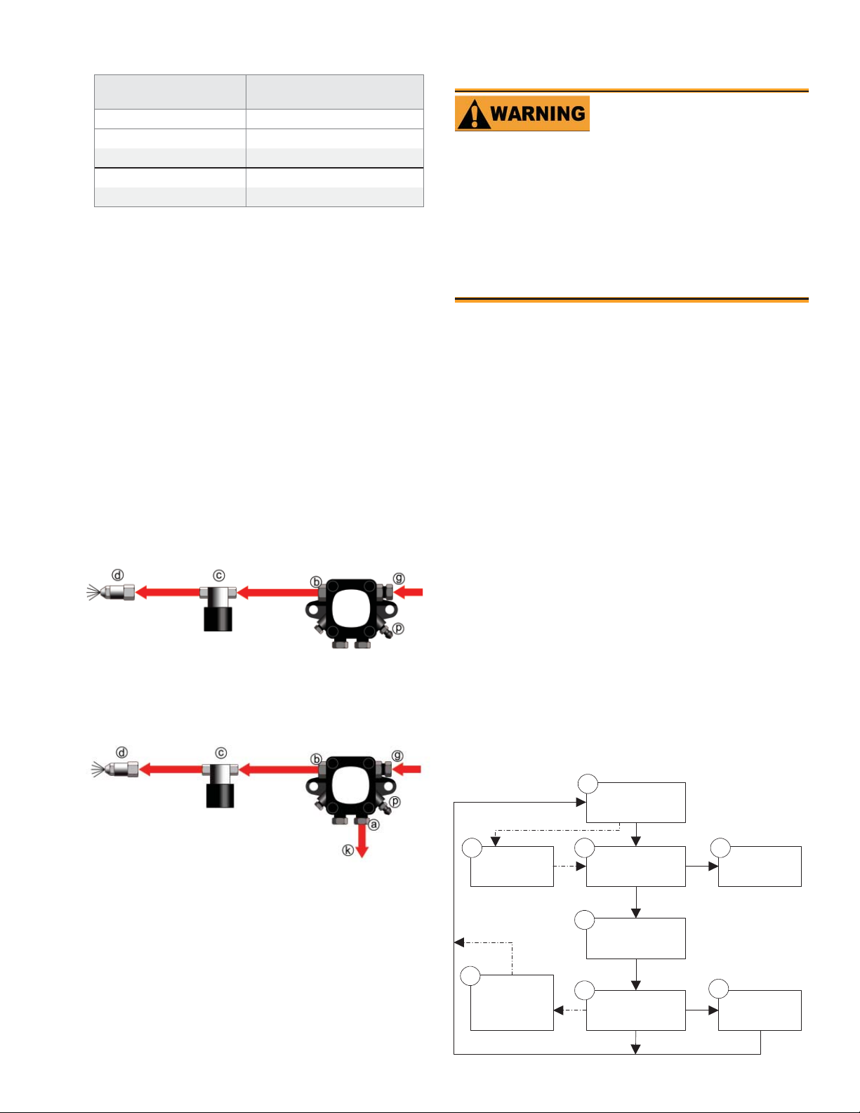
Table 2 - Fuel unit gearset capacities
Fuel unit
model number
A2EA-6520 17
A2VA-7116 17
A2YA-7916 20
B2VA-8216 21
B2YA-8916 25
Install two high-quality shut-off valves in accessible
y
locations on the oil supply line. Locate one valve close
to the tank. Locate the other valve close to the burner,
upstream of the fuel fi lter.
Gearset capacity
(gallons per hour)
Wire the burner — R7184
Electrical Shock Hazard
Electrical shock can cause severe personal in-
jury or death.
Disconnect electrical power before installing or servic-
y
ing the burner.
y
Provide ground wiring to the burner, metal control enclosures and accessories. (This may also be required to
aid proper control system operation)
y
Perform all wiring in compliance with the National
Electric Code ANSI/NFPA 70 (Canada CSA C22.1).
Burner fuel fl ow
One-pipe systems – See Figure 7 for the fuel fl ow path.
y
Figure 7 is based on type B fuel unit.
y
Oil supply connects to one of the fuel unit inlet ports.
y
y
Two-pipe systems – See Figure 8 for the fuel fl ow paths
for two-pipe oil systems.
y
Figure 8 is based on type B fuel unit .
y
Oil supply connects to one of the fuel unit inlet ports.
Oil return connects to the fuel unit return port. (Install
the by-pass plug in the fuel unit for two-pipe systems.)
Figure 7 - One-pipe oil fl ow with “B” pump
125-200 psig
125-200 psig
Figure 8 - Two-pipe oil fl ow with “B” pump
3502
Install the burner and all wiring in accordance with the National
Electrical Code and all applicable local codes or requirements.
Wire the burner in compliance with all instructions provided by
the appliance manufacturer. Verify operation of all controls in
accordance with the appliance manufacturer’s guidelines.
S
equence of operation — typical
1. Standby — The burner is idle, waiting for a call for heat.
When a call for heat is initiated, there is a 2- to 6-second
delay while the control performs a safe start check.
2. Valve-on delay — As applicable, the ignition and motor are
turned on for a 15-second prepurge.
3. Trial for ignition (TFI) — The fuel valve is opened, as applicable. A fl ame should be established within the 15-sec-
ond lockout time (30-second lockout time is available).
4. Lockout — If fl ame is not sensed by the end of the TFI, the
control shuts down on safety lockout and must be manually reset. If the control locks out three times in a row, the
control enters restricted lockout. Call a qualifi ed service
technician.
5. Ignition carryover — Once fl ame is established, the igni-
tion remains on for 10 seconds to ensure fl ame stability. It
then turns off.
6. Run — The burner runs until the call for heat is satisfi ed.
The burner is then sent to burner motor-off delay, as applicable, or it is shut down and sent to standby.
125-200 psig
125-200 psig
Figure 9. - Typical sequence of operation
1
Standby
Legend
a Return port
b Nozzle port
c Oil valve
d Nozzle & adapter
Nozzle pressure – The fuel unit nozzle port pressure
y
g Inlet port
k Return line to oil tank
p Air bleed valve
is factory set at 140 psig. Some original equipment
manufacturer burner applications may call for a lower
pressure to obtain a required fi ring rate. Do not change
this pressure unless directed to do so by the appliance
3503
2
Valve-on
delay
8
Motor-off
delay
(postpurge)
3
5
carryover
6
Trial for
ignition
Ignition
Run
4
Lockout
7
Recycle
manufacturer.
6104 BCF3 R02 Page 9
Page 10
7. Recycle — If the fl ame is lost while the burner is fi ring, the
control shuts down the burner, enters a 60-second recycle
delay, and then repeats the ignition steps outlined above. If
the fl ame is lost three times in a row, the control locks out
to prevent continuous cycling with repetitious fl ame loss
caused by poor combustion.
8. Burner motor-off delay — If applicable, the fuel valve is
closed and the burner motor is kept on for the selected postpurge time before the control returns the burner to standby.
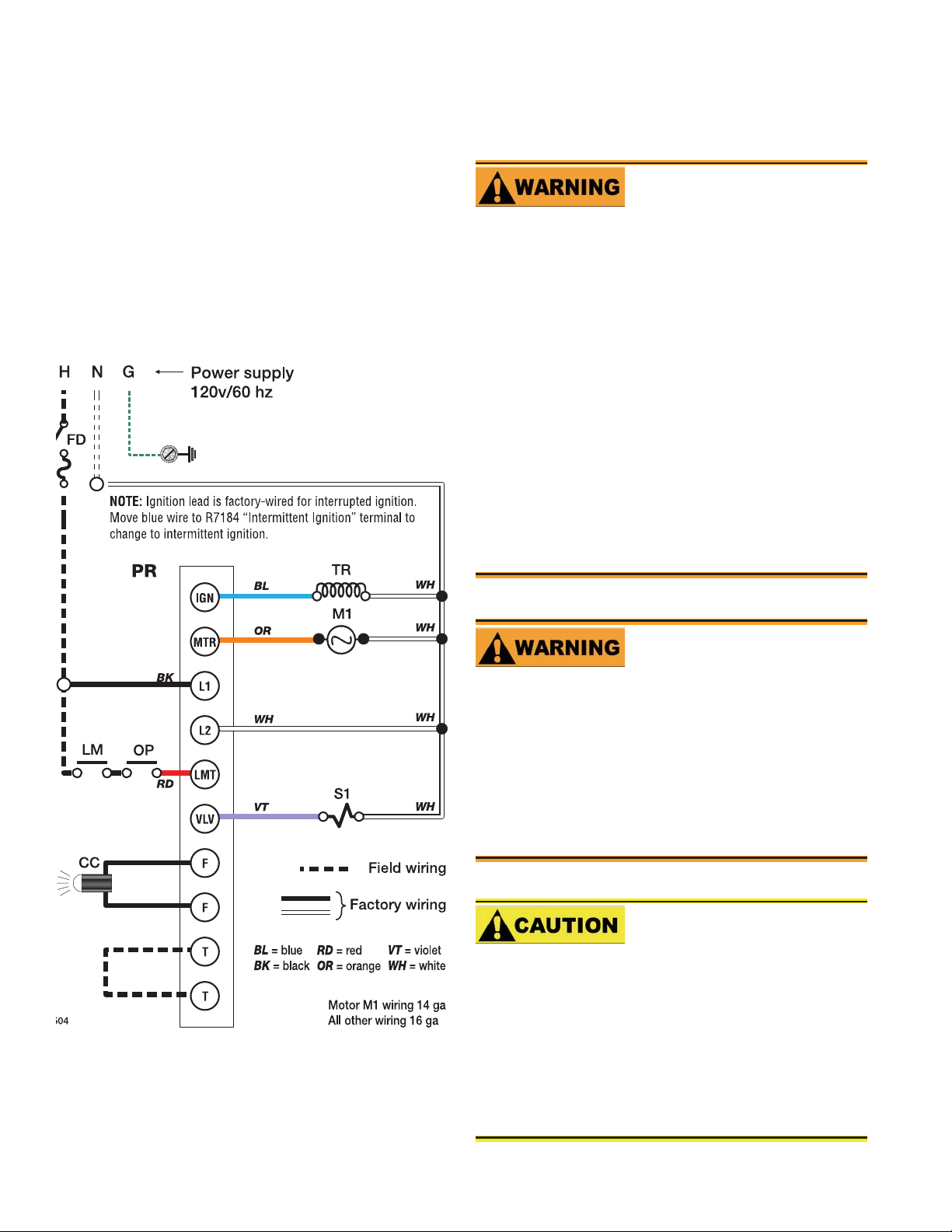
See Figure 10 for a typical wiring diagram, with R7184 oil
primary, for reference purposes only.
Figure 10. - Typical wiring
Prepare the bur ner for
start-up
Professional Installation
and Service Required
Incorrect installation and mishandling of start-
up could lead to equipment malfunction and result in asphyxiation, explosion or fi re.
This burner must be installed and prepared for start-up
y
by a qualifi ed service technician who is trained and ex-
perienced in commercial oil burner system installation
and operation.
y
Do not attempt to start the burner unless you are fully
qualifi ed.
y
Do not continue with this procedure until all items in
the “Prepare the burner for start-up” section have been
verifi ed.
y
Carefully follow the wiring diagrams, control instruction sheets, fl ame safeguard sequence of operation, test
procedures and all appliance manufacturer’s directions
that pertain to this installation.
y
If any of these items are not clear or are unavailable,
call Beckett at 1-800-645-2876 for assistance.
Do Not Bypass Safety
Controls
Tampering with, or bypassing safety controls
could lead to equipment malfunction and result
in asphyxiation, explosion or fi re.
Safety controls are designed and installed to provide
y
protection.
y
Do not tamper with, or bypass any safety control.
y
If a safety control is not functioning properly, shut off
all main electrical power and fuel supply to the burner
and call a qualifi ed service agency immediately.
Keep Service Access
Covers Securely Installed
These covers must be securely in place to
prevent electrical shock, damage from external elements, and protect against injury from
moving parts.
All covers or service access plates must be in place at
y
all times except during maintenance and service.
y
This applies to all controls, panels, enclosures, switches, and guards or any component with a cover as part
of its design.
Page 10 6104 BCF3 R02
Page 11

Start-up checklist
Combustion air supply and venting have been inspected
and verifi ed to be free of obstructions and installed in ac-
cordance with all applicable codes.
Oil nozzle has been selected correctly and securely in-
stalled in the nozzle adapter.
Fuel unit by-pass plug has not been installed for one-
pipe oil system.
By-pass plug has been installed for two-pipe oil
system.
Fuel connection to nozzle line assembly is secure.
Dimension Z has been set per this instruction manual.
Fuel supply line is correctly installed, the oil tank is suf-
fi ciently fi lled, and shut-off valves are open.
Burner is securely mounted in appliance, with pressure
fi ring plate and gasket installed for pressurized chamber
application.
Appliance has been fi lled with water (boilers) and controls
have been operationally checked.
Burner has been installed in accordance with appliance
manufacturer’s instructions (when available).
Also refer to appliance manufacturer’s instructions (when
available) for start-up procedures.
Z dimension
Should be set per the Set Z Dimension instructions
detailed earlier in this manual. The acorn nut (Fig-
ure 6, item c) should never be loosened once the Z
dimension is initially set.
Table 3 - Initial indicator adjustment plate
settings (head position)
Approximate adjust-
ing plate setting
0 1.65
1 1.75
3 2.00
4 2.50
5 3.00
6 3.50
NOTE
Initial air settings (Table 4)
Loosen the air band and shutter, and adjust to the
y
approximate fi ring rate settings given in Table 4.
These initial settings should be adequate for starting the
y
burner. Once the burner is in operation, the air settings
will be adjusted for best performance as discussed later in
this manual.
Follow the procedures described later in this manual for
y
fi ne-tuning the air settings.
Table 4 - Initial air shutter and band settings
Firing rate,
gph
1.65 5 0
1.75 10 2
2.00 10 4
2.50 10 5
Approximate head settings
Shutter Band
Firing rate, gph
These settings are approximate,
and can vary depending on
actual job conditions and overfi re
pressure.
Initial head position (Figure 6)
The indicator plate assembly markings correspond to head
y
position settings.
Loosen the fastener (Figure 6, item d) and slide the
y
indicator plate until the number on the indicator plate
corresponds to the initial head setting listed in Table 3, for
the desired fi ring rate.
When the head position has been set, tighten the fastener
y
and the spline nut.
6104 BCF3 R02 Page 11
3.00 10 6
3.50 10 8
These settings are approximate, and can
NOTE
Set appliance limit controls
Set the appliance limit controls in accordance with the
y
appliance manufacturer’s recommendations.
Prepare the fuel unit for air venting
To vent air from one-pipe oil systems, attach a clear hose
y
to the vent plug on the fuel unit. Provide a container to
catch the oil. Loosen the vent plug.
Vent the air as described in the next section under Start
y
the burner.
vary depending on actual job conditions
and overfi re pressure.
Page 12
Start the Burner
Explosion and Fire
Hazard
Failure to follow these instructions
could lead to equipment malfunction
and result in heavy smoke emission,
soot-up, hot gas puff-back, fi re and
asphyxiation hazards.
Do not attempt to start the burner when excess oil has
y
accumulated in the appliance, the appliance is full of
vapor, or when the combustion chamber is very hot.
y
Do not attempt to re-establish fl ame with the burner
running if the fl ame becomes extinguished during start-
up, venting, or adjustment.
y
V apor-Filled Appliance: Allow the unit to cool off and
all vapors to dissipate before attempting another start.
y
Oil-Flooded Appliance: Shut off the electrical power
and the oil supply to the burner and then clear all accumulated oil before continuing.
y
If the condition still appears unsafe, contact the Fire
Department. Carefully follow their directions.
y
Keep a fi re extinguisher nearby and ready for use.
Repeat the previous steps if needed, until the pump is
y
fully primed and the oil is free of bubbles. Then terminate the call for heat, and the control will resume
normal operation.
Resetting from restricted lockout
If the control locks out three times in a row without a
y
complete heat cycle between attempts, the lockout becomes restricted. A qualifi ed service technician should
be called to inspect the burner.
Disable function
Any time the motor is running, press and hold the reset
y
button to disable the burner. The burner will remain off
as long as the button is held and will return to standby
when released
CAD cell resistance check
While the burner is fi ring, and after the ignition has
y
been turned off, press and release the reset button (hold
1/2 second or less) to check the cad cell resistance. The
LED will fl ash 1 to 4 times, depending on the cad cell
resistance (refer to the table below).
Starting the burner and venting air
Priming the pump
Initiate a call for heat
y
While the ignition is on, press and release the reset but-
y
ton on the R7184 control (hold 1/2 second or less). If
the control has not locked out since it’s most recent
complete heat cycle, the lockout time will be extended
to 4 minutes (45 seconds in earlier units), and the ignition will remain on the entire heat cycle.
Bleed the pump until all froth and bubbles are purged.
y
If prime is not established within the extended lockout
time, the control will lock out. Press the reset button to
reset the control and return to the functions listed in the
previous step.
Hot Gas Puff-back and
Heavy Smoke Hazard
Failure to bleed the pump properly
could result in unstable combustion,
hot gas puff-back and heavy smoke.
Do not allow oil to intermittently spray into a hot com-
y
bustion chamber while bleeding.
y
Install a gauge in the nozzle discharge port tubing or
fully open the pump bleed valve to prevent oil spray
from accumulating in the combustion chamber when
venting air from the fuel pump.
y
Ensure that all bubbles and froth are purged from the
oil supply system before tightening the pump air bleed
valve.
Number of LED
Flashes
1 Normal (0 to 400)
2 Normal (400 to 800)
3 Normal (800 to 1600)
4 Limited (1600-Lockout)*
* Lockout can occur above 4000 ohms.
LED Indicator Status
On Flame sensed
Off Flame not sensed
Flashing (1/2 sec off - 1/2
sec on)
Flashing (2 sec off - 2 sec
on)
Set combustion using instruments
Cad Cell Resistance (ohms)
Lockout/Restricted
Lockout
Recycle
Allow the burner to run for approximately 5 to 10 min-
1.
utes.
2.
Set the stack or over-fi re draft to the level specifi ed by
the appliance manufacturer.
y
Natural Draft Applications; typically over-fi re draft
is -0.01” or -0.02” w.c.
y
Direct Venting; typically may not require draft adjustment.
Page 12 6104 BCF3 R02
Page 13

High Effi ciency/Positive Pressure Appliances; also
y
vary from traditional appliances (see manufacturer’s
recommendations).
3.
Follow these four steps to properly adjust the burner:
Maintenance and Ser-
vice
Step 1: Adjust the air shutter/band until a trace of smoke
is achieved.
Step 2: At the trace of smoke level, measure the CO
(or O2) . This is the vital reference point for further
adjustments. Example: 13.5% CO
Step 3: Increase the air to reduce the CO2 by 1.5 to 2
percentage points. (O2 will be increased by approximately 2.0 to 2.7 percentage points.) Example: Reduce CO2 from 13.5% to 11.5% (2.6% to 5.3% O2).
Step 4: Recheck smoke level. It should be Zero.
This procedure provides a margin of reserve air
y
to accommodate variable conditions.
If the draft level has changed, recheck the
y
smoke and CO
if necessary
Once combustion is set, tighten all fasteners on air band,
4.
air shutter and escutcheon plate.
Start and stop the burner several times to ensure satis-
5.
factory operation. Test the primary control and all other
appliance safety controls to verify that they function according to the manufacturer’s specifi cations.
2 levels and readjust the burner,
(2.6% O2)
2
Annual Professional
Service Required
2
Tampering with or making incorrect
adjustments could lead to equipment malfunction and result in
asphyxiation, explosion or fi re.
Do not tamper with the burner or controls or make
y
any adjustments unless you are a trained and qualifi ed
service technician.
y
To ensure continued reliable operation, a qualifi ed
service technician must service this burner annually.
y
More frequent service intervals may be required in
dusty or adverse environments.
y
Operation and adjustment of the burner requires
technical training and skillful use of combustion test
instruments and other test equipment.
Annual service — by qualifi ed service techni-
cian
Have the burner inspected, tested and started at least annually
by a qualifi ed service technician. This annual test/inspection
should include at least the following:
Check the breech draft pressure against the appliance
6.
manufacturer’s recommended setting (typically + 0.1”
W .C.). If the breech pressure is higher or lower than recommended level, adjust the appliance breech damper to
achieve the specifi ed setting. Recheck the smoke and
CO
levels. Adjust burner air if necessary.
2
Replace the oil supply line fi lter. The line fi lter cartridge
must be replaced to avoid contamination of the fuel unit
and nozzle.
Inspect the oil supply system. All fi ttings should be leak-
tight. The supply lines should be free of water, sludge and
other restrictions.
Remove and clean the pump strainer if applicable.
Replace the nozzle with the exact brand, pattern, gph, fl ow
rate and spray angle.
Clean and inspect the electrodes for damage, replacing
any that are cracked or chipped.
Check electrode tip settings. Replace electrodes if tips are
rounded.
Inspect the igniter spring contacts.
Clean the cad cell len’s surface, if necessary.
Inspect all gaskets. Replace any that are damaged or would
fail to seal adequately.
Inspect the combustion head and air tube. Remove any
carbon or foreign matter. Replace all damaged units with
exact parts.
Clean the blower wheel, air inlet, air guide, burner housing and static plate of any lint or foreign material.
If motor is not permanently lubricated, oil motor with a
few drops of SAE 20 nondetergent oil at each oil hole.
DO NOT over oil motor. Excessive oiling can cause motor failure.
6104 BCF3 R02 Page 13
Page 14

Check motor current. The amp draw should not exceed the
nameplate.
Check all wiring for secure connections or insulation
breaks.
Check the pump pressure and cutoff function.
Check primary control safety lockout timing.
Check ignition system for proper operation.
Inspect the vent system and chimney for soot accumula-
tion or other restriction.
Clean the appliance thoroughly according to the manufac-
turer’s recommendations.
Check the burner performance. Refer to the section “Set
combustion with test instruments”.
It is good practice to make a record of the service per-
formed and the combustion test results.
Monthly maintenance
Observe combustion air openings and vent system
for integrity. Openings must be clean and free of
obstructions.
Check oil lines and fi ttings to verify there are no leaks.
Observe burner ignition and performance to verify smooth
operation.
Shut the system down if you observe abnormal or
questionable operation. Call a qualifi ed service agency for
professional inspection and service.
— by owner
Page 14 6104 BCF3 R02
Page 15
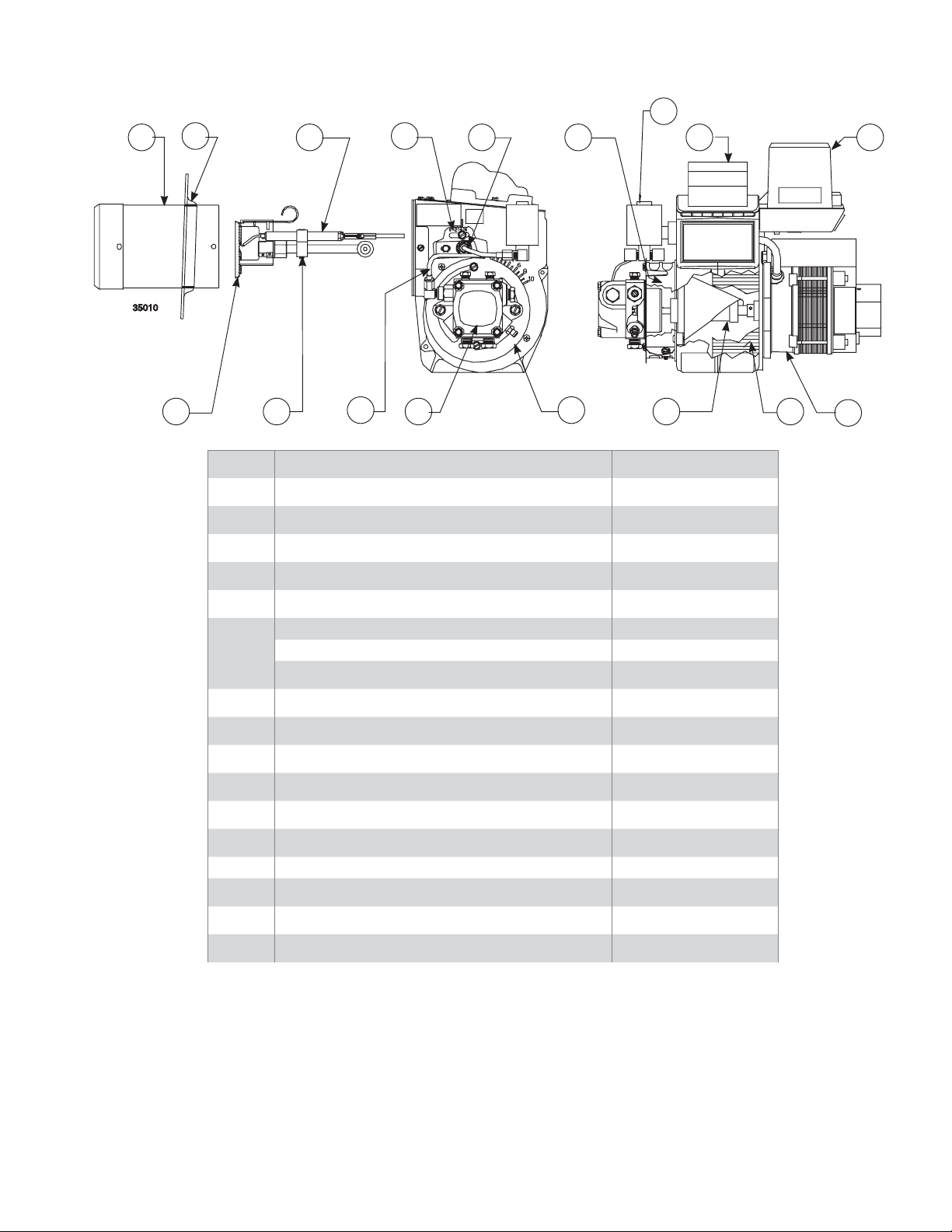
Replacement parts
1
2
3
10
11
18
8
1415
6 5
Item Part Name/Description Part Number
1 Air T ube Specify
2 Flange Kit Specify
3 Electrode Assembly Specify
4 Air Shutter 3709
5 Nozzle Line Assembly Specify
6
7 Fuel lines Specify Lengths
8 Air Band 3492
10 Adjusting plate assembly 5721
11 Spline Nut 3666
12 Fuel Pump Specify
13 Coupling 2454
14 Control Specify
15 Ignitor & Baseplate 51771U
16 Motor - 1/7 PSC 21805U
7
Head Assembly - KY - Tube A 5913
Head Assembly - KZ - Tube B 51820
12
4
1713
16
17 Blower Wheel 21837U
18 Blocking Oil Solenoid Valve 2182602U
6104 BCF3 R02 Page 15
Page 16

Limited Warranty Information
Limited
WARRANTY
For Residential, Commercial and Specialty Burners
The R. W. BECKETT CORPORATION (“Beckett”) warrants to persons who purchase its Beckett burners from Beckett for resale or for
incorporation into a product for resale (“Customers”) that its equipment is free from defects in material and workmanship under normal use and
service for 60 months from the date of manufacture for Residential Burners and 18 months from the date of manufacture for Commercial and
Specialty Burners. Residential burner models include: AF, AFG, AFII, NX, SF, SR and SMG. Commercial burner models include: CF375,
CF500, CF800, CF1400, CF2300A, CF2500, CF3500A, CG10, CG15, CG25 and CG50. Specialty burner models include: ADC, ADCP, ARV,
SDC and SM. The provisions of this warranty are extended to individual major burner components as follows:
a) 60 months from date of manufacture for all Beckett-branded major components, except for 12 Vdc components.
b) 18 months from date of manufacture for all non-Beckett-branded major components and Beckett branded 12 Vdc components.
Note: Normal service items found to be defective upon receipt by the customer are covered by this warranty.
THIS WARRANTY DOES NOT EXTEND TO EQUIPMENT SUBJECTED TO MISUSE, NEGLECT, OR ACCIDENT: NOR DOES THIS WARRANTY APPLY
UNLESS THE PRODUCT COVERED BY IT IS PROPERLY INSTALLED BY A QUALIFIED, COMPETENT TECHNICIAN, WHO IS LICENSED WHERE
STATE AND LOCAL CODES REQUIRE, AND WHO IS EXPERIENCED IN MAKING SUCH INSTALLATIONS, IN ACCORDANCE WITH THE LATEST
EDITION OF NFPA NO. 31 OF THE NATIONAL FIRE PROTECTION ASSOCIATION, THE LATEST EDITION OF THE NATIONAL FUEL GAS CODE (NFPA
NO. 54) AND IN ACCORDANCE WITH ALL APPLICABLE LOCAL, STATE AND NATIONAL CODES HAVING JURISDICTIONAL AUTHORITY.
Equipment, which is defective in material or workmanship and within the warranty period, may be returned for credit as follows:
Beckett Burners, Beckett-branded major components and non-Beckett-branded major components that came as original equipment on a Beckett burner
or were sold as a replacement part by Beckett should be returned, freight prepaid, to Beckett’s home office. Credit will be issued to the customer unless
the returned equipment is determined by Beckett to be out of warranty or damaged by user, in which case the equipment will be scrapped.
Note: Beckett is not responsible for any labor cost for removal and replacement of equipment.
THIS WARRANTY IS LIMITED TO THE PRECISE TERMS SET FORTH ABOVE, AND PROVIDES EXCLUSIVE REMEDIES EXPRESSLY IN LIEU OF ALL OTHER
REMEDIES, AND IN PARTICULAR THERE SHALL BE EXCLUDED THE IMPLIED WARRANTIES OF MERCHANTABILITY AND FITNESS FOR A PARTICULAR
PURPOSE. IN NO EVENT WILL BECKETT BE LIABLE FOR ANY INCIDENTAL OR CONSEQUENTIAL DAMAGE OF ANY NATURE.
authorizes any person to assume for Beckett any other liability or obligation in connection with the sale of this equipment, Beckett’s liability and Customer’s
exclusive remedy being limited to credit as set forth above.
Beckett neither assumes nor
R.W. BECKETT CORPORATION
P.O. Box 1289 Elyria, Ohio 44036
Form No. 61545 R72905
R.W. BECKETT CORPORATION
U.S.A.: P.O. Box 1289 · Elyria, Ohio 44036
www.beckettcorp.com
Canada: R.W. Beckett Canada, Ltd. · Unit #3, 430 Laird Road · Guelph, Ontario N1G 3X7
Printed in U.S.A. 12/2006 © R.W. Beckett Corporation
Page 16 6104 BCF3 R02
 Loading...