

Page 1

S80 with
• MLS Basic Card
• MLS Professional Card
en
Assembly and Operating Instructions
Door Control Unit
Important information for:
•
Fitters
• Electricians
• Users
Please forward accordingly!
These instructions must be kept for future reference.
Becker-Antriebe GmbH
35764 Sinn/Germany
www.becker-antriebe.com
Page 2
Assembly and Operating Instructions
Table of Contents
Introduction ................................................................................................................................................................2
Warranty .....................................................................................................................................................................2
Safety instructions ......................................................................................................................................................3
Basic safety measures .................................................................................................................................................3
Intended use .............................................................................................................................................................. 4
Abbreviations used ......................................................................................................................................................4
Overview of unit .......................................................................................................................................................... 4
Overview of functions ..................................................................................................................................................5
Installing the control unit ..............................................................................................................................................6
Fitting and removing a control card ............................................................................................................................... 6
Electrical connection ................................................................................................................................................... 7
Operator controls ........................................................................................................................................................7
Checking the direction of movement .............................................................................................................................8
Setting the door end limits ...........................................................................................................................................8
Electrical connection/operation of external control sensors and safety devices ................................................................9
Connection and function of the switching outputs .........................................................................................................11
Retrotting and operation of radio control system ........................................................................................................ 12
Setting the DIP switches ............................................................................................................................................ 14
Indicator LED’s ......................................................................................................................................................... 15
Overview of control times ........................................................................................................................................... 16
What should I do if ... ? ............................................................................................................................................... 16
Position of terminals and components ........................................................................................................................ 17
General wiring diagram .............................................................................................................................................. 18
Specications ........................................................................................................................................................... 19
Introduction
When installing the equipment and setting the functions, please observe the Operating and Installation Instructions.
Note
These Operating and Installation Instructions apply to the S80 Door Control Unit with MLS Basic Card and
MLS Professional Card for actuating drives with mechanical limit switching.
Warranty
Structural modications and incorrect installation which are not in accordance with these and our other instructions can result
in serious injuries, e.g. crushing of limbs. Therefore, structural modications may only be carried out with our prior approval
and strictly in accordance with our instructions, particularly the information contained in these Assembly and Operating Instructions.
Any further processing of the products which does not comply with their intended use is not permitted.
The end product manufacturer and tter have to ensure that all the current statutory, ofcial and, in particular, EMC regulations are adhered to during utilisation of our products, especially with regard to end product manufacture, installation and
customer advice.
2
Page 3

Safety instructions
The following safety instructions and warnings serve to avert dangers and to prevent personal injuries and damage to property. Please retain these instructions for future reference.
Caution
Attention
Note
Denotes a potentially hazardous situation. If this is not avoided, injuries can
result.
Denotes a potentially hazardous situation. If this is not avoided, the product
or property in its vicinity can be damaged.
Denotes hints for use and other useful information.
Basic safety measures
Caution
Please read this manual thoroughly before carrying out work on the system. Always observe the manual
and the safety instructions contained in it.
• When the control is opened, there is an electrical voltage of up to 400 V. Danger to life due to electric shock.
• Work on the electrical equipment must only be carried out by a qualied electrician.
• Only use the control in accordance with its intended use!
• Never decommission or bypass safety devices.
• Do not operate the system if the safety devices are damaged.
• Fault elimination must only be performed by an authorised technician. In the event of a system malfunction, the
system must be shut down immediately and the malfunction rectied as quickly as possible. The system must
only be commissioned by an authorised technician.
• Observe the generally applicable legal regulations (safety, accident prevention) as well as these safety instructions, particularly the regulation of the employers’ liability insurance associations, EN 12453 “Requirements
for safe use of power-operated doors” as well as the relevant applicable VDE standards.
• The operator must ensure that the system is only operated in perfect condition and that the safety devices are
checked regularly for functional efciency by an expert (before commissioning and as required, but at least
once a year; at least once every six months if a non self-testing light barrier is used). Proof of the necessary
checks must be provided in the form of a test report. This test report must be led in the log book.
• The estimated service life of the control is 100.000 operations.
• Drives with connection cable H05VVF are to be used only inside the building. In case of installation outside,
the cable is to be protected inside conduit.
3
Page 4

Assembly and Operating Instructions
Intended use
The control unit must be used as intended with Becker door drives with mechanical limit switches. If other controls are used,
the warranty entitlement will become invalid! This control must not be used for doors which have not been designed for this
type of control!
Abbreviations used
IMP - Impulse Button
LS - Photoelectric Barrier
MLS - Mechanical Limit Switch (mechanical limit switching)
ELS - Electronic Limit Switch (electronic limit switching)
SKS/USA - Bottom Rail Sensor
VES - Pre-Limit Switch
AUTO/WZL - Automatic Closing/Reclosing (Wiederzulauf)
BES - Becker Electronic System
DW Testing - Pressure Switch Testing (pneumatic safety edge)
Overview of unit
Basic Control Unit S80
MLS Basic Card
MLS Professional Card
4
Page 5

Overview of functions
Function MLS Basic Card MLS Professional Card
Setting mode (up/down in dead-man mode) X X
Automatic ascent (UP) X X
Automatic descent (DOWN) X
Anti-pull-in cable safety X X
Slack rope switch debounced X X
Button input: UP/STOP/DOWN/STOP X
Automatic closing X
Partial opening X
Pneumatic safety edge X
Electrical safety edge X
Safety edge switchover: 1.2 kOhm/8.2 kOhm X
Optoelectronic safety edge: FRABA OSE X
Photoelectric barrier X
Yard light X
Trafc lights/door status indicator X X
Warning lamp X
Power supply lamp X X
LED UP X X
LED DOWN X X
LED Operating status X
LED ERROR Code X
LED Safety edge X
LED Pre-limit switch X
Voltage output (24 V DC / 200 mA) X X
1)
Operates only when a safety edge is used
1)
5
Page 6
Assembly and Operating Instructions
Installing the control unit
Install the control unit so that the operator controls are readily accessible. The cover of the housing with the 3-way pushbutton
switch has to be removed for installation purposes.
The unit is mounted on the wall with four 4 mm dia. screws (max. head dia. 8 mm) using the four fastening holes, which also
take the screws to t the cover, in accordance with the dimensioned drawing on the bottom of the housing.
If necessary, you can t more cable glands for sensor cables and indicating cables.
Attention
When removing housing knockouts in order to t more cable glands, take care not to damage any compo-
nents on the control boards or the housing itself. Only t sealing cable glands which ensure the housing
has the correct degree of protection.
When retting the cover, ensure that the seal and the seal groove are clean and that the cover is mounted
properly.
Tighten up the housing cover screws carefully. Only then will the IP 65 degree of housing protection remain intact.
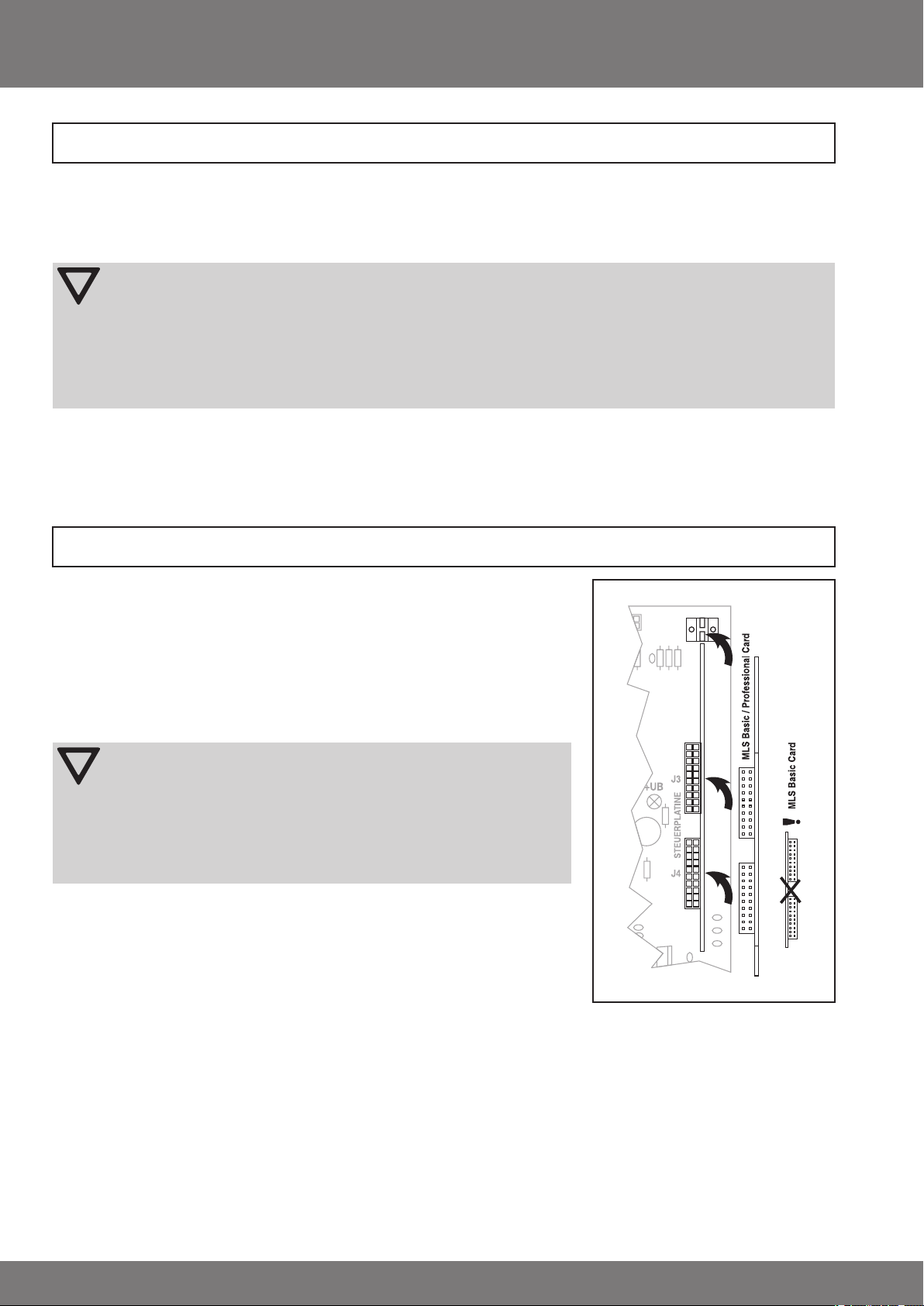
Fitting and removing a control card
The S80 door control system for drives with mechanical limit switching can be converted/upgraded by changing plug-in control cards. The following control cards
are available:
• MLS Basic Card
• MLS Professional Card
Before changing a control card, disconnect the entire door control unit from the
mains and open the cover of the control box.
Attention
The regulations for handling elements with an electrostatic risk
must be complied with. The MLS Professional Card may only be
used in combination with a safety edge. When delivered, safety
devices may be bridged. When changing from the MLS Basic Card
to the MLS Professional Card, always ensure that no non-permissible bridging exists or, if such bridging does exist, ensure that it
is removed.
Carefully pull out the control card connected to slot J3/J4 and insert the new control card at slot J3/J4 on the S80 motherboard as illustrated opposite. With the
MLS Basic Card ensure that the board is the right way round.
6
Page 7

Electrical connection
Caution
The control unit may only be connected by an electrician.
Observe the relevant VDE standards.
During all installation work the equipment must always be securly disconnected from the mains.
When connecting, refer to the specications of the S80. The indicated maximum values are not to be
supassed!
Installing the Mains Connection
The working voltage of the S80 door control unit is 3-phase 400 V/230 V, 50 Hz. For connection to the main power supply,
please use a 1,2 m long cable and a 16A/6h CEE socket outlet with direct access to the control unit to ensure that the plug is
readily accessible. Alternatively, connect the control unit via a non-detachable installation cable complete with local isolation
(for the positions of the terminals and the wiring diagram refer to pages 37 and 38).
Attention
For xed installation, a main switch must be connected to the S80 control unit or directly to the power
line in reach of the control unit. Protect the mains lead for the control unit with a 3-phase AC automatic
cut-out (3 x 10 A).
Connecting the Drive to the Control Unit
The drive cable is usually already attached to the control unit. If not, connect the 12-core drive cable to terminals E and PE in
accordance with the wiring diagram. The 11 black wires of the drive cable are numbered 1 to 11, corresponding to the numbers
of terminals E. The green/yellow earth wire must be connected up to one of the 3 PE earth terminals ( ).
Operator controls
UP Button
If the MLS Professional Card is used, pressing the UP button opens the door and keeps it open. When the top end limit has
been reached or if a safety function responds, the door stops automatically. If the UP button is pressed whilst the door is closing, the door stops instantly and after a delay of 0.5 s (time Z0) it moves to the top end limit.
If the MLS Basic Card is used, the unit can either be in dead-man mode (the UP button has to be kept pressed - if it is released,
the door stops) or in automatic mode (the UP button is pressed once and the door moves automatically to the top end limit),
depending on the position of DIP switch DIP 1.
STOP Button
Pressing the STOP button stops the door instantly when it is opening or closing.
DOWN Button
If the MLS Professional Card and a safety edge are used, pressing the DOWN button closes the door automatically. If no safety
edge is connected, only the dead-man mode is possible. If the closing safety edge or the photoelectric barrier responds, the
door stops (safety edge: stopping time Z2 = 0.3 s, photoelectric barrier: stopping time Z0 = 0.5 s) and, depending on the setting (DIP switch 1.3), moves to the top end limit or clears an obstacle (clearance time Z1 = 2 s).
If the MLS Basic Card is used, only the dead-man mode is possible in the DOWN direction, i.e. the DOWN button has to be
kept pressed. If it is released, the door stops.
EMERGENCY OFF Button (optional)
If the EMERGENCY OFF button is pressed, the drive is switched off. The door is brought to a sustained halt and the LED +UB
lamp goes out. The door can only move again when the EMERGENCY OFF button has been unlocked.
Master Switch (optional)
With the master switch the system can be completely disconnected from the mains.
7
Page 8

Assembly and Operating Instructions
Checking the direction of movement
Note
In order to facilitate working on the
control unit, the cover can be offset
laterally and held in place by just two
screws. That way all operator controls and indicator lamps are accessible.
The direction of drive rotation depends on how the
three mains phases are connected to the control
unit; it has to be checked rst. To do this proceed
as follows:
• Insert the CEE plug into the CEE socket, or turn
on the isolator switch.
• Check to make sure the control unit is in setting
mode by verifying
- whether DIP switch DIP 1 is in the OFF posi-
tion (MLS Basic Card)
- whether the Pilot lamp is ashing (MLS Professional Card). If it is not, press the Prog programming button (for approx.
1 s) until the Pilot lamp begins to ash.
• Using the UP and DOWN buttons check whether the direction of door movement agrees with the buttons pressed. Also
observe the UP and DOWN direction indicator lamps on the motherboard of the S80.
If the direction of movement does not correspond to the button commands, proceed as follows:
• Disconnect the S80 control unit from the mains.
• Change over two phases at the power supply terminals, e.g. the cables at terminals L1 and L3 (see positions of the terminals and the wiring diagram).
• Check the direction of movement again.
MLS Professional Card
MLS Basic Card
Setting the door end limits
Note
To set the door end limits you can also use the programming handset (Art. no. 4023 200 027 0).
The door end limits are set using the operating cams of the door drive. Proceed as described in the operating instructions for
the drive.
MLS Basic Card
Operating cams S7 and S8 (orange and green cams) serve to actuate the indicator outputs.
MLS Professional Card
Operating cam S7 (orange cam) serves as a pre-limit switch.
Note
When the ‘Partial opening’ function (half the height of the door) is activated, the setting of operating cam
S8 (green cam) serves as the top end limit.
The Testing pre-limit switch (S7, orange cam) must be set so that the maximum height of the door above
the ground is 50 mm. The VES lamp on the Professional Card serves as a check.
To leave the setting mode, press the Prog programming button on the MLS Professional Card again. When the Pilot LED is on
continuously, normal mode has been resumed.
8
Page 9

Electrical connection/operation of external control sensors
and safety devices
Note
Before connecting external control sensors you should rst check the direction of door movement and
set the end limits of the door drive.
Voltage output for external control devices (MLS Basic + MLS Professional)
A direct-current voltage is provided at terminals A- and B+ (24 V DC / 200 mA) for external control devices: U = 24 V DC, I
= 200 mA. This voltage output is protected by ne-wire fuse F2 with 200 mA slow-blow.
EMERGENCY STOP button (MLS Basic + MLS Professional)
An EMERGENCY STOP button can be connected to terminals A2 and B2. The jumper between terminals A2 and B2 (EMERGENCY STOP) must be removed to enable subsequent connection of an external EMERGENCY STOP button.
If the EMERGENCY OFF button is pressed, the drive is switched off. The door is brought to a permanent stop and the +UB LED
goes out. Door movement is only possible again after releasing the EMERGENCY STOP button.
External triple push button (MLS Basic + MLS Professional)
An external triple push button can be connected at terminals A3, B3, A4 and B4 (STOP ↓ ↑). This is identical in function to the
triple push button on the front of the control. The jumper between terminals A3 and B4 must be removed in order to connect
an external triple push button.
Wicket Door Switch / Spring Break Safety Device (MLS Basic and MLS Professional)
A wicket door switch and/or spring break safety device can also be connected across terminals A3 and B4, in series with
the STOP button of the external 3-way pushbutton switch if tted to connect a wicket door switch and/or spring break safety
device, remove the wire jumper across terminals A3 and B4.
Induction loop (MLS Basic + MLS Professional)
An induction loop for automatic door opening can also be connected at terminals A4 and B4, possibly in parallel with the
UP button of the external 3-way pushbutton. If possible, the induction loop should be set so that it gives a CONTINUOUS UP
COMMAND.
Slack Rope Switch (MLS Basic + MLS Professional)
A slack rope switch can be connected across terminals A10 and B10 (SCHLAFFSEIL/ÜL). For installation the wire jumper
across terminals A10 and B10 must be removed. This input is debounced via an internal timing element of approx. 0.1 s (de-
pending on the bounce of the switch). If the slack rope switch responds beyond that time, the door stops instantly no matter
what position it is in. All other door movements are inhibited for as long as the switch is being operated.
max
Caution
The “slack rope switch” input is not monitored to such an extent that errors can be ruled out. If a combined
slack rope/trap switch is used, this must be connected to the terminals A2 and B2 EMERGENCY-OFF.
Pull in safety cable/switch (MLS Basic and MLS Professional)
A safety switch can be connected across terminals A5 and B5 (STOP-UP) to prevent the curtain from being drawn in the UP
direction. For installation the wire jumper across terminals A5 and B5 must be removed. If this safety device responds during
upward movement, the door stops instantly. Upward movement remains inhibited. The door now has to be moved to the bottom end limit manually by pressing the DOWN button (↓).
Light barriers in use must comply with safety category 3 according to EN 954.
Only applies to MLS Professional Card
The control unit switches to the dead-man mode (inching mode). Only when the bottom limit position has been reached does
the control unit switch back to automatic mode.
External 1-way Switch (MLS Professional only)
An external 1-way pushbutton switch can be connected across terminals A13 and B13 (IMP). The pushbutton commands
are executed one after the other in the sequence UP - STOP - DOWN - STOP (pulse-edge evaluation when the button contact
closes). If there is a fault, the pushbutton commands are executed one after the other in the sequence UP - STOP - UP.
Partial Opening (MLS Professional only)
A switch can be connected across terminals A11 and B11 (half the door height) in order to activate the Partial Opening function (also called half door height). If Partial Opening is activated, the setting of limit switch S8 (green cam) of the drive serves
as the top end limit.
9
Page 10

Assembly and Operating Instructions
Automatic Closing
A switch can be connected across terminals A12 and B 12 (AUTO/WZL) in order to activate the Automatic Closing function.
If Automatic Closing is activated, the door is closed by the control unit after the automatic closing time (time Z4 = 60 s) has
elapsed. If the Early Warning function is activated (DIP switch 1.6 in the ON position), before commencing the automatic closing procedure an early warning is given by actuating relay 1 with an early warning time Z3 = 3 s.
By attaching the timer module to system plug X1 of the MLS Professional Card III, the reclosing time can be variably set between 2 and 240 s.
For a description of the timer module, see „Timer Module Technical Information“
Photoelectric Barrier (MLS Professional only)
A photoelectric barrier can be connected across terminals A7 and B7 (PB). For installation the wire jumper across terminals
A7 and B7 must be removed.
This control input has two functions:
• If the photoelectric barrier responds during downward movement (Fault2 lamp ashes), the door stops instantly. After an
internal time of 0.5 s (time Z0) has elapsed, the S80 opens the door again. Depending on the setting of DIP switch 1.3, the
control unit moves the door clear of the obstacle or to the top end limit.
• If the door is open or being opened and the light beam is interrupted and then released again, the automatic closing time
Z4 is reduced to 3 s in the event that DIP switch 1.8 is in the ON position. If DIP switch 1.8 is in the OFF position, the auto-
matic closing time Z4 will run again.
Safety Edge (MLS Professional only)
The following safety edge systems can be connected to door control unit S80 directly:
• Pneumatic safety edge or
• Electric safety edge or
• Optoelectronic safety edge: FRABA OSE
The sensor required is integrated into the control unit (self-monitoring sensor as per pr EN 12453). The pneumatic safety edge
or the electric safety edge is connected up to terminals A6 and B6 (SKS/USA). To ensure that the spiral rubber-insulated
cable is monitored, the 1.2 kW resistor clamped across terminals A6 and B6 is supplied with the unit. It must be connected
inside the pressure switch contact or at the end of the electric safety edge in accordance with the wiring diagram for the S80.
In the case of factory-assembled electric safety edges, check their terminating resistance. Safety edges with a 1.2 kΩ or 8.2
kΩ terminating resistor may be used. Connect the OSE optoelectronic safety edge made by FRABA to terminals A8, A9 and
B8 (OSE) direct without the need for any terminating resistor (A8 - brown wire, A9 - green wire, B8 - white wire). To adapt the
control unit to the respective safety edge, set DIP switches 1.1, 2.1 and 2.2 according to the following table.
Type of safety edge DIP 1.1 DIP 2.1 DIP 2.2
Pneumatic safety edge 1.2 kOhm ON ON ON
Pneumatic safety edge 8.2 kOhm ON ON OFF
Electric safety edge 1.2 kOhm OFF ON ON
Electric safety edge 8.2 kOhm OFF ON OFF
Optoelectronic safety edge FRABA OSE OFF OFF OFF
Caution
When using optoelectronic safety edge FRABA OSE DIP switch 2.1 must always be set to the OFF posi-
tion or else the self-monitoring system of the sensor integrated into the control unit will be deactivated.
If a pneumatic switching rail is used, DIP switch 1.1 must be set to the ON position, as otherwise the func-
tion of the pneumatic rail will not be correctly monitored. When delivered, safety devices may be bridged.
Before initial use, always check that no non-permissible bridging exists.
If the safety edge responds during downward movement (bottom rail sensor LED SKS/USA lights up), the door is stopped
instantly by the S80 control unit. After an internal time of 0.3 S. (time Z2) has elapsed, the S80 opens the door again.
Depending on the setting of DIP switch 1.3, the control unit moves the door clear of the obstacle or to the top end limit.
10
Page 11

Connection and function of the switching outputs
Switching Outputs
The S80 door control unit has two potential free relay switching outputs (changeover contacts, see wiring diagram) each with
a switching capacity of 250 V AC / 5 A.
MLS Basic Card
The relays are actuated by the operating cams S7 and S8 of the drive:
• The orange cam S7 de-energizes relay 2
• The green cam S8 de-energizes relay 1
As a result it is possible to implement, for example, a door status indicator.
MLS Professional Card
With the MLS Professional Card the two relays have different switching functions, depending on the settings of the DIP switches 1.5,1.6 and 1.7 in accordance with the following table.
Switching functions of the indicator outputs DIP 1.5 DIP 1.6 DIP 1.7
Door status
Relay 1 switches on at the top door end limit.
Relay 2 switches on at the bottom door end limit.
In the event of door movement, both relays are off.
Trafc lights + yard light with time delay
Relay 1 switches on at the top door end limit
(trafc light red/green via changeover contacts).
At the beginning of each door movement relay 2 switches on and remains on - at
the end of each door movement it switches off after a delay of 120s (time Z6).
Trafc lights + yard light control pulse
Relay 1 switches on at the top door end limit (trafc light red/green via change over
contacts). At the beginning of each door movement relay 2 switches on for 1s
(passing contact, pulse to actuate a time-delay relay).
Warning light + yard light with time delay
Relay 1 switches on when the door leaves either of the end limits and remains on.
At the beginning of each door movement relay 2 switches on and remains on 120s (time Z6) after the end of each door movement it switches off after a delay.
If automatic closing has been set, the two relays switch on as soon as the early
warning time (3 s, time Z3) begins.
Warning light ashing + yard light pulse
Relay 1 switches on when the door leaves either of the end limits and ashes at a
rate of 1 Hz.
At the beginning of each door movement relay 2 switches on for 1s
(passing contact, pulse to actuate a time-delay relay).
If automatic closing has been set, the two relays switch on as soon as the early
warning time (3 s, time Z3) begins.
Warning light ashing + yard light with time delay and early warning
Relay 1 switches on 3 s (early warning time Z3) before the door leaves either of
the end limits and remains on.
Relay 2 switches on 3 s (early warning time Z3) before beginning each door movement and remains on - at the end of each door movement it switches off with a
delay of 120s (time Z6).
Warning light ashing + yard light control pulse, with early warning
Relay 1 switches on for 3 s (early warning time Z3) before the door leaves either of
the end limits and ashes at a rate of 1 Hz.
Relay 2 switches on 3 s (early warning time Z3) before the beginning of each door
movement for 1 s (passing contact, pulse to actuate a time-delay relay).
OFF OFF OFF
ON OFF OFF
ON OFF ON
ON ON OFF
ON ON ON
OFF ON OFF
OFF ON ON
11
Page 12

Assembly and Operating Instructions
Retrofitting and operation of radio control system
Door control unit S80 with MLS Professional Card can be provided with a 1-channel or 4-channel radio remote control system.
If such a system has been ordered with the control unit, the radio
receiver will already have been installed in the control unit. If this
is the case, please proceed to the section “Operation”.
Note
The radio control system cannot be used in con-
junction with the MLS Basic Card. It will not operate.
If a radio remote control system is being retrotted, you must rst
install the receiver board on the motherboard. For this disconnect
the entire door control system from the mains.
Insert the radio control receiver board in slot J1 at the top right of the S80 motherboard, as shown on the drawing. Make sure
the board is the right way round.
Operation
1-channel radio remote control
The 1-channel radio remote control operates in the same way as the 1-way pushbutton switch. The pushbutton commands
are executed one after the other in the sequence UP - STOP - DOWN - STOP. If there is a fault, the pushbutton commands are
executed one after the other in the sequence UP - STOP - UP.
4-channel radio remote control
The 4-channel radio remote control has the following functions:
Button 1: As with the 1-channel pushbutton switch the pushbutton commands are executed one after the other in the se-
quence UP - STOP - DOWN - STOP. If there is a fault, the pushbutton commands are executed one after the other
in the sequence UP - STOP - UP.
Button 2: Operation identical to that of UP button.
Button 3: Operation identical to that of DOWN button. In the event of a fault this button is activated in the dead-man mode.
Button 4: Operation identical to that of STOP button.
receiver board
J1 FUNK
Caution
When using a radio control system the person controlling the door must have a clear view of the door and
its surrounding area during door movement and must not be in a dangerous position.
In setting mode and in the event of a malfunction, the radio receiver board must be removed from the PCB
slot J1.
Programming the Hand-held Transmitter Code
The hand-held radio control transmitter has been coded by the manufacturer. The radio control receiver must be set to this
code. To program the hand-held transmitter code in the radio control receiver proceed as follows:
• Press Program Channel 1 on the radio control receiver. The relevant red signal LED begins ashing. You can program the
hand-held transmitter code within the next 15 s.
• To do this press the button on the hand-held transmitter for approx. 2 s. The programming of the hand-held transmitter
code is conrmed by the signal LED on the receiver staying on continuously.
• Now let go of the button on the hand-held transmitter.
You can program the other 3 buttons on the four-channel receiver in the same way. All in all you can program up to 60 different transmitter codes (buttons) for each receiver. The 61st code will not be accepted by the receiver. In conjunction with the
1-channel receiver you can therefore use up to 60 1-channel hand-held transmitters and in conjunction with the 4-channel
receiver you can use up to 15 4-channel hand-held receivers (if all the buttons are used).
Note
You can combine all hand-held transmitters with all receivers.
Example:
You have an application with 4 doors each of which is controlled by an S80 with 1-channel radio control
receiver. If you use 4-channel hand-held transmitters and assign each button to one of the 4 receivers,
you can control all 4 doors independently of one another with just one hand-held transmitter. If you re-
quire more than 60 transmitter codes, please contact us. Here too we can offer customised solutions.
12
Page 13

Deleting All the Transmitter Codes Programmed
To delete the hand-held transmitter codes in the radio control receiver proceed as follows:
• Press Program Channel 1 on the radio receiver and keep it pressed. The red signal LED begins to ash slowly. After approx.
5 s the red signal lamp ashes quickly.
• Keep the button pressed until the red signal lamp goes out.
• When the signal lamp goes out, all the codes of the 1-channel radio control receiver and all 4 channels on the 4-channel
radio control receiver will have been deleted.
• Only now let go of the button again.
13
Page 14

Assembly and Operating Instructions
ON
DIP 1
ON
DIP 1
Setting the DIP switches
MLS Basic Card
Switch Position Illustration Function
ON
Automatic mode in UP direction
DIP 1
OFF
Dead-man mode in UP direction
MLS Professional Card
Switch Position Illustration Function
DIP 1.1
DIP 1.2
DIP 1.3
DIP 1.4
DIP
1.5/1.6
DIP 1.7
DIP 1.8
DIP 2.1
DIP 2.2
ON
OFF
ON
OFF
ON
OFF
ON
OFF
ON/ON
ON/OFF
OFF/ON
OFF/OFF
ON
OFF
ON
OFF
ON
OFF
ON
OFF
DIP 1 DIP 2
ON DIP
1 2345678
DIP 1 DIP 2
ON DIP
1 2345678
DIP 1 DIP 2
ON DIP
1 2 345678
DIP 1 DIP 2
ON DIP
1 2 345678
DIP 1 DIP 2
ON DIP
123 45678
DIP 1 DIP 2
ON DIP
123 45678
DIP 1 DIP 2
ON DIP
123 4 5678
DIP 1 DIP 2
ON DIP
123 4 5678
DIP 1 DIP 2
ON DIP
12345678
DIP 1 DIP 2
ON DIP
12345678
DIP 1 DIP 2
ON DIP
12345678
DIP 1 DIP 2
ON DIP
12345678
DIP 1 DIP 2
ON DIP
1234567 8
DIP 1 DIP 2
ON DIP
1234567 8
DIP 1 DIP 2
ON DIP
1234567 8
DIP 1 DIP 2
ON DIP
1234567 8
DIP 1 DIP 2
ON DIP
12345678
DIP 1 DIP 2
ON DIP
12345678
DIP 1 DIP 2
ON DIP
12345678
DIP 1 DIP 2
ON DIP
12345678
ON
Pneumatic (DW) safety edge connected, DW testing is activated
12
ON
Electric or FRABA OSE safety edge connected
12
Deactivate at the bottom end limit via switching pulse from the electric,
ON
pneumatic or optoelectronic safety edge
12
ON
Deactivate at the bottom end limit via the cam limit switches on the drive
12
ON
Move up to the top end limit after a safety stop
12
ON
Move clear of the obstacle after a safety stop with a clearance time Z1 = 2 s
12
Relieve the safety edge at the bottom end limit (reversing) with reversing
ON
time Z5 = 100 ms
12
ON
No relief (reversing) at the bottom end limit
12
Relay 1: warning light, early warning
ON
only for automatic closing
12
Relay 1: trafc lights,
ON
door at top end limit
12
Relay 1: warning light,
ON
always with early warning
12
Relay 1: door status,
ON
door at top end limit
12
Relay 1: warning light ashing,
ON
ash rate 1 Hz
12
Relay 1: warning light
ON
on continuously
12
Automatic closing time Z4 is reduced to 3 s after releasing the photoelec-
ON
tric barrier
12
ON
Automatic closing time (time Z4) re-runs via light barrier function.
12
ON
Electric or pneumatic safety edge connected
1 2
ON
Optoelectronic safety edge FRABA OSE connected
1 2
ON
Terminating resistance of safety edge = 1.2 kOhm
1 2
ON
Terminating resistance of safety edge = 8.2 kOhm
1 2
Relay 2: yard light
Relay 2: yard light
Relay 2: yard light
Relay 2: door status,
door at bottom end limit
Relay 2: yard light,
control pulse 1 s
Relay 2: yard light, remaining on
for 120 s (time Z6)
14
Page 15

Indicator LED’s
Basic Control Unit S80
LED Illustration Indication Meaning
POWER
+UB
on Power supply connected
off No power supply connected
UP
DOWN
AUF
ZU
on Door moves UP
on Door moves DOWN
MLS Professional Card
LED Illustration Indication Meaning
on Normal mode
Pilot
Betr
contin. ash Setting mode (dead-man mode)
In order to switch to normal mode (automatic), please push the programming button Prog.
STOP button pressed, wicket door switch/spring break safety device
triggered or Emergency Stop transistor faulty
Fault1
Stör1
on
1 ash Door running time exceeded
2 ashes Pre-limit switch testing set too high
3 ashes No switch pulse from the safety edge at the bottom end limit
4 ashes Limit switch Up and Down activated simultaneously.
contin. ash Internal communication fault or main processor faulty
on Hardware test routine being processed
1 ash Safety circuit of drive has been triggered
2 ashes Safety edge actuated just before downward movement of door or
internal bottom rail sensor faulty
Fault2
Stör2
3 ashes Slack rope switch/pull in cable safety/switch
4 ashes Internal communication fault or monitoring processor faulty
5 ashes
The door has run up against an obstacle 5 times because automatic
closing is activated
6 ashes The unit connected to system socket X1 is faulty
contin. ash Photoelectric barrier actuated
USA
VES
USA
VES
on Safety edge actuated
off Safety edge not actuated
on Pre-limit switch actuated
off Pre-limit switch not actuated
off DIP switch released/control times unchanged
Sonder
Sonder
1 ash DIP switch inhibited/control times unchanged
2 ashes DIP switch released/control times changed
on DIP switch inhibited/control times changed
15
Page 16

Assembly and Operating Instructions
Overview of control times
Time Duration Description
Z0
Z1
Z2
Z3
Z4
Z5
Z6
Z7
Z8
Z9
500 ms Stopping time for opposite UP command due to UP button or photoelectric barrier
2 s Clearance time when moving clear of an obstacle
300 ms Stopping time for opposite UP command due to safety edge
3 s Early warning time
60 s Closing time if automatic closing is activated; adjustable from 2 - 240 s when time module is mounted
100 ms Reversing time to relieve the safety edge
120 s Time the yard light remains on
90 s Maximum door running time for door run time monitoring
1 s Waiting time for safety edge signal at bottom end limit
6 s Monitoring time for monitoring the set height of the VES test
What should I do if ... ?
Caution
All malfunctions must be rectied by qualied electricians!
Fault Possible cause and remedy
No reaction to pressing the button,
POWER lamp is not lit
No reaction to pressing the button,
POWER lamp is lit
No auxiliary power at terminals A-/B+
(24 V DC / 300 mA)
Note
Please also observe the indication of faults and errors by the LED’s on the pc board of the basic control
unit S80 and MLS Professional Card.
• Check supply voltage (terminals L3/L2/L1/N (MAINS)).
• Check miniature fuse F1 (400 mA, slow blow).
• Check EMERGENCY OFF button (terminals A2/B2
(EMERGENCY OFF)).
• Check safety circuit of the drive (terminals E1 ... E11,
emergency hand crank (chain), drive temperature, safety
limit switches (S1F/S2F, yellow cams).
• Check terminals A3/B4 (STOP), A5/B5 (STOP-UP), A7/
B7 (photoelectric barrier) and A10/B10 (SLACK ROPE).
If these pairs of terminals are not assigned, they must be
jumpered.
• Check whether you are using the correct control card
for the drive: MLS Basic Card/MLS Professional Card for
drives with mechanical limit switching, ELS Basic Card/
ELS Professional Card for drives with electronic limit
switching (BES).
• Check miniature fuse F2 (315 mA, slow blow).
16
Page 17

CONTROL PANEL
J3
J4
J2
+UB
J1 RADIO
F1
400 mA T
F2
200 mA T
321
W
MOTOR
E
L3L2L1
L1NN
8910
11
4
5
6
7
E
V U
PE
–A
2
3
456789101112
13
+B
2
3
4
5
6
7
89101112
13
CONTROL INPUTS
RELAY 1 RELAY 2
OPEN CLOSED
MAINS
RELAY 2
RELAY 1
MAIN SWITCH
(optional)
CONTACTOR
TRANSFORMER
Cycle
counter
(optional)
NOT-AUS
STOP-AUF
STOP
SKS/USA
IMP
AUTO/WZL
1/2 Torhöhe/STOP X
Überlastschalter
br
gn
ws
OSE
LS
24 V DC / 200 mA
Basic Control Unit S80
Position of terminals and components
MLS Basic Card
DIP 1
ON
MLS-Basic-Card
MLS Professional Card
Stör1 VES Sonder Betr USA
MLS-Professional-Card
X1
Stör2
Prog
ON DIP
12345678
EL
DW
OSE 8K2
ON
12
DIP 1
1K2
DIP 2
17
Page 18

Assembly and Operating Instructions
General wiring diagram
Drive with mechanical limit switching
S1F - Safety limit switch OPEN
Drive
S3F
123
Connect according to the numbers indicated
4
S4F
S1F
S5 S6 S7 S8
S2F
5 67891011PE
12
S2F - Safety limit switch CLOSE
S3F - Safety limit switch Emergency Operation
S4F - Thermal protection switch
S5 - Operation limit switch OPEN
S6 - Operation limit switch CLOSE
S7 - Pre-limit switch Testing
S8 - Function limit switch 1/2 door height
321 4567
WVU
Drive
Mains
PE
PE
PE
3 x 400 V / 230 V AC, 50/60 Hz
L3 L2 L1L1 NN
5
8910 11
Contactor
F2
Transformer
F2
200 mAT
Relay 1Relay 2
slack
rope
switch
External
Emergency
OFF-switch
Radio Control
green red
T
400 mA
A
Int. 3-way pushbutton switch
24 V DC / 200 mA
- 2345678910 11 12 13
- 2345678910 11 12 13
B
Wicket door/spring break safety
+UB
green
SKS/USA
Plug-in card
EL - E
lectric safety edge
or
DW -
Safety edge with DW contact (pneumatic)
R=1k2 / 8k2
OSE (FRABA)
optical safety edge
S=Transmitter
E=Receiver
Connection
white=B8
brown=A8
green=A9
R
18
STOP
Ext. 3-way pushbutton switch
OFF-switch
Emergency
DW
-UP
STOP
Tapping box
R
SKS / USA
FRABA OSE
LS
resistor
1.2 kOhm/8.2 kOhm
white=B8
brown=A8
green=A9
E
S
IMP
Slack rope/
Overload protection
AUTO/WZL
1/2 door height/Stop X
Page 19

Specications
Type S80 with MLS Basic Card MLS Professional Card
Power supply 3N~ 230/400 V 50/60 Hz
Rated output of motor 2.0 kW max.
Control voltage* 24 V DC
Control circuit max. 125 mA
Dimensions of housing 182 mm x 254 mm x 90 mm (W x H x D)
Weight approx. 1.5 kg (not incl. connecting cable)
Degree of protection IP65
Relay switching capacity each 250 V AC/5 A AC-1
Ambient temperature range 0 °C ... +50 °C
Battery backup on site 3 x 10 A
*) Basic insulation for operating voltage
19
Page 20

4023 630 822 0c 02/13
 Loading...