

Page 1

S30, S30-V..
en
Assembly and Operating Instructions
Door control unit
Important information for:
• Fitters / • Electricians / • Users
Please forward accordingly!
These instructions must be kept safe for future reference.
4023 630 402 0b15/01/2018
Becker-Antriebe GmbH
Friedrich-Ebert-Straße 2-4
35764 Sinn/Germany
www.becker-antriebe.com
Page 2

Table of contents
General ................................................................................................................ 3
Warranty .............................................................................................................. 3
Safety instructions ................................................................................................ 4
Intended use ........................................................................................................ 6
Abbreviations/symbols in these instructions............................................................ 7
Assembly ............................................................................................................. 8
Electrical connection............................................................................................. 9
Controls ..............................................................................................................10
Checking the running direction .............................................................................10
Setting the door limit positions ..............................................................................11
Connection and function of external control sensors and safety devices ...................14
Setting the DIP switches .......................................................................................18
Status indications ................................................................................................18
Maintenance .......................................................................................................20
Cleaning..............................................................................................................20
Technical data .....................................................................................................20
Wiring .................................................................................................................22
Declaration of conformity .....................................................................................24
2
Page 3
General
This door control unit is a high-quality product with the following performance characteristics:
• Evaluation of safety sensors on the door (e.g. closing edge surveillance, pull-in
safety device and similar)
• Evaluation of additional safety devices on the door (e.g. light barriers, light grids
and similar)
• Evaluation of control sensors on the door (e.g., pull switch, induction loop and sim-
ilar)
• Evaluation of EMERGENCY STOP control sensors
• Supplying sensors and control sensors with 12 V safety extra-low voltage
• Operation of application-specific outputs
Please observe these Assembly and Operating Instructions when installing and setting
up the equipment.
Explanation of pictograms
CAUTION
ATTENTION
CAUTION indicates a hazardous situation
which, if not avoided, could result in injury.
ATTENTION indicates measures that must be
taken to avoid damage to property.
Denotes user tips and other useful information.
Warranty
Structural modifications and incorrect installation which are not in accordance with
these and our other instructions can result in serious injuries, e.g., crushing of limbs.
Therefore, structural modifications may only be carried out with our prior approval and
strictly in accordance with our instructions, particularly the information contained in
these Assembly and Operating Instructions.
Any further processing of the products which does not comply with their intended use is
not permitted.
The end product manufacturer and fitter have to ensure that all the relevant current
statutory, official and, in particular, EMC regulations are adhered to during utilisation of
our products, especially with regard to end product manufacture, installation and customer advice.
3
Page 4
Safety instructions
The following safety instructions and warnings are intended to avert hazards and to
prevent property damage and personal injury. It is important to follow these instructions.
General information
• In addition to the fire and accident prevention regulations, the safety
instructions given in EN 12453, EN 12445, EN 12978, VDE 0100, EN
50110, EN 60204, EN 50178, EN 60335 and ASR A1.7 must be observed.
• All work, including maintenance and cleaning, on electrical installa-
tions as well as other system parts must always be performed by
trained technicians, in particular qualified electricians.
• The limits given in the technical data must not be exceeded.
• The illustrations contained in these instructions are intended as an
aid to understanding how the product operates. Therefore, the illustrations may differ from the actual display on the product.
Caution
• When electrical or electronic equipment and units are
operated, certain components are live. Physical injuries
or damage to property can result in the event of unauthorised interventions or failure to heed warnings.
• When moving the doors in dead-man mode it is neces-
sary to ensure that the door region is visible to the operator, since safety equipment such as the safety edge of
the light barrier is not effective in this operating mode.
• Operating the control unit when the housing is open is
not allowed.
Attention
• Turning on or operating a control unit when dew is
present on the unit is not allowed. It can lead to the control unit being ruined.
4
Page 5
Operating notes
• Do not allow children to play with permanently mounted regulating
or control devices.
• Keep remote control units out of the reach of children.
• Systems have to be checked regularly by authorised specialists for
wear and damage.
• It is forbidden to use a damaged controller.
• To avoid damage to the operator controls, they should not be
touched with sharp objects. Only use your fingers to use the operator controls.
• Do not operate equipment if people or objects are within the danger
zone.
• The control unit is designed to have a service life of 100,000 operat-
ing cycles.
Caution
• If the connecting cable of this unit is damaged, it must
be replaced by the manufacturer or their customer service department or a similarly qualified person in order
to avoid hazards.
Notes on electrical connection and assembly
• All applicable standards and regulations for electrical installation
must be complied with.
• Disconnect the electrical supply from the equipment before in-
stalling and connecting accessories and extras, and protect against
unauthorised reconnection in accordance with the safety regulations.
• Only use spare parts, tools and accessory devices which have been
approved by the manufacturer. Unapproved third-party products or
modifications to the system and its accessories represent a risk to
your safety and the safety of others. This means that the use of unapproved third-party products, or modifications which have not
been agreed with or approved by us, are prohibited. We do not accept liability for damage or injury arising from such actions.
5
Page 6
• Operating the control unit with a detached CEE plug is only permiss-
ible if the mains supply can be isolated from all poles of the control
unit using an appropriate switch. The mains plug, or any switch used
as a substitute, must be easily accessible.
Caution
• The potential-free signal relay may only be used for
switching low voltage. The switching of mains voltage is
not permitted.
Commissioning notes
• The setting of the parameters, limit positions, jumpers and other op-
erator controls must only be carried out by trained personnel.
Caution
• The setting of the parameters and limit positions, and
the function of the safety devices must be checked by
trained technicians.
Intended use
The control unit in these instructions is exclusively designed for indoor use for the operation of roller doors, vertical lift gates, sectional doors, flexible (fabric) doors or indirectly operated door systems.
This type of control unit must not be used in potentially explosive areas.
The mains cable and any other connected cables are not designed for carrying the
control unit. Therefore always carry the control unit by the housing.
Other applications, uses and modifications are not permitted in order to protect the
safety of the users and others, since these actions can impair the system’s safety and
carry the risk of personal injury and property damage. The manufacturer does not accept liability for damage or injury arising from such actions.
Always observe the information in these instructions when operating or repairing the
system. The manufacturer does not accept liability for damage or injury resulting from
improper use.
6
Page 7
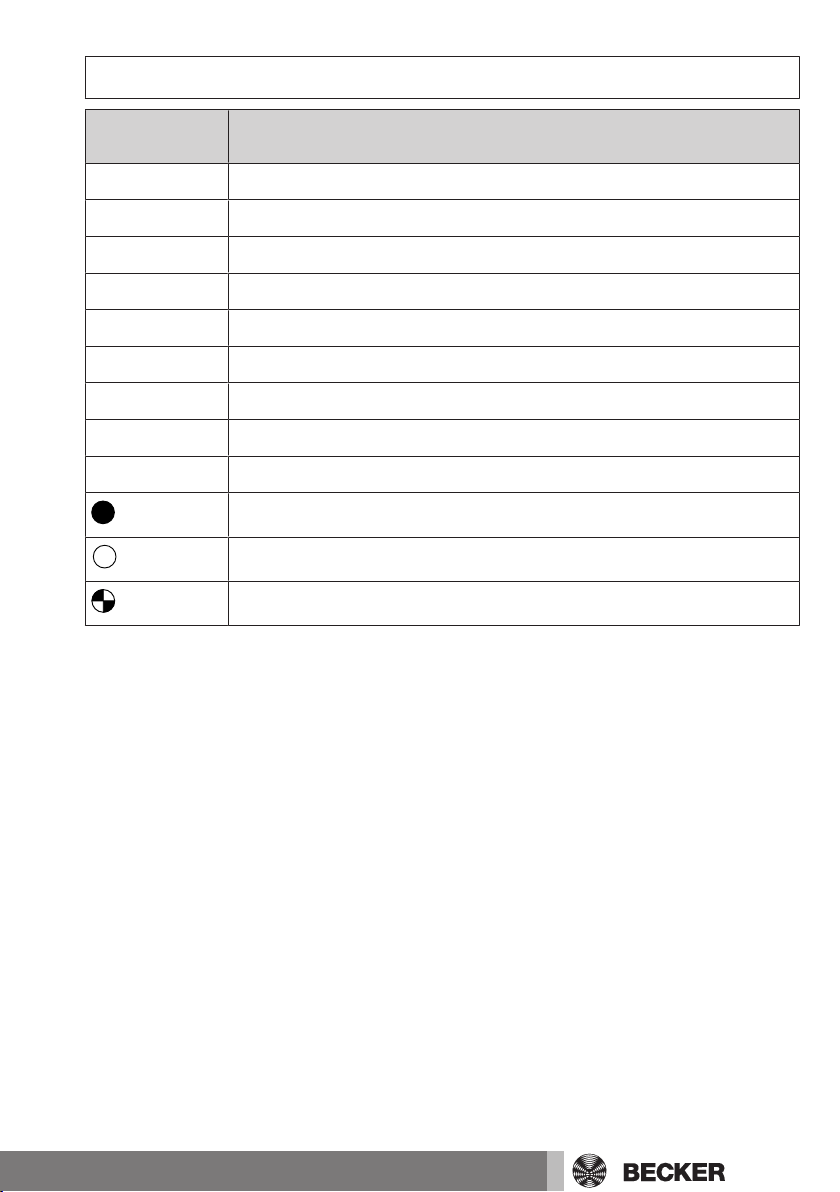
Abbreviations/symbols in these instructions
Abbreviation /
symbol
IMP
LS
SKS
DW testing
EL
OSE
NA
VES
AWZ
Description
Impulse button
Light barrier
Closing edge safety device
Pressure monitor testing
Electric safety edge
Optical safety device
Emergency Stop
Pre-limit switch
Automatic reclosing
LED lights up
LED off
LED flashes
7
Page 8
Assembly
Do not select an assembly location exposed to electromagnetic fields, such as locations in the direct vicinity of contactors (power relay), mains transformers, ignition
transformers, fluorescent tubes, etc., or their connecting cables. Protect the control
unit from direct sunlight and driving rain.
Open the cover of the control unit. Remove the cable from the cover and carefully place
the cover to one side. Remove the required cut-outs in the bottom part of the housing.
Cut in at the edges to make the cut-outs easier to remove.
Assemble the control unit at a suitable operating height (at least 1500 mm from the
ground). Mount the housing with 4 screws (max. diameter of screw head 7.5 mm) inserted through the holes provided in the corners.
Reconnect the cover cable and set the DIP switch. You can now close the control unit.
8
Page 9

Electrical connection
Caution
The control unit must only be connected by a qualified
electrician!
Observe the relevant VDE standards!
During all installation work, the equipment must always be
securely disconnected from the mains!
When connecting, refer to the technical data of the control
unit and the drive. The indicated maximum values must not
be exceeded! Only drives and associated connecting lines
with reinforced or double insulation to the control circuit
according to EN 60335 may be used.
Installing the mains connection
The operating voltage of the door control unit is 3 x 400 V AC, 50/60 Hz (L1, L2, L3, N,
PE). For connection to the mains, install an approx. 1.2 m long mains cable with CEE
16A/6h plug and a CEE 16A/6h socket in the immediate vicinity of the control unit in
such a way that the plug is easily accessible, or connect the control unit via a non-detachable installation cable (see “Position of the terminals and connecting diagram”).
Attention
For permanent installations, a main switch must be connected in the immediate vicinity of the control unit to the
power line or directly to the control unit. Protect the power
line for the control unit with a 3-phase AC automatic cutout with 3 x 10 A.
Connecting the drive to the control unit
To connect the Becker sectional door drive to the door control unit, connecting cables
are available in a variety of lengths. The connecting cable has a plug-in cable gland on
both sides. Connection is established via the 4-phase plug (M-motor) and the 8-phase
plug (E-limit switch).
The yellow/green protective conductor wire must be connected to the protective conductor terminal PE ( ).
9
Page 10

Controls
Labelling Function Function:
Brief actuation
OPEN OPEN command
STOP If drive is in motion: STOP
If drive is at a halt: Light on/
off if light function with
stopping time is set
CLOSE CLOSE command
Function:
Actuation > 5 sec.
Confirmation of a fault,
storage of a limit position
It is not possible to move the door while the "STOP" button
is actuated or a safety device in the emergency stop circuit has triggered.
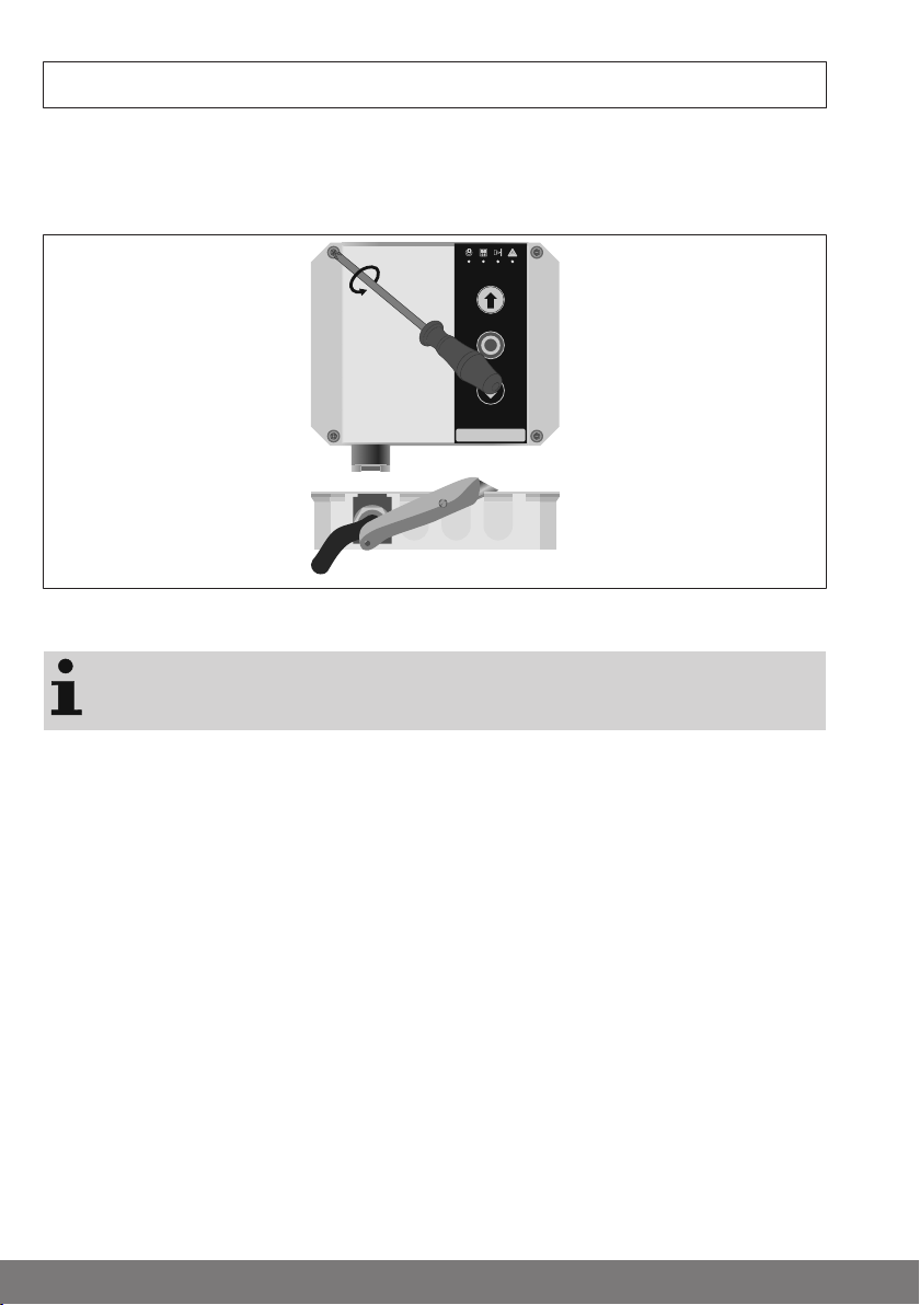
Checking the running direction
Open the cover of the door control unit by undoing the four cover screws and re-attach
the cover offset upwardly.
The direction of drive rotation depends on how the three mains phases are connected
to the control unit and has to be checked first. Proceed as follows:
• Move the door into the semi-opened position using the emergency manual opera-
tion function.
• Insert the CEE plug into the CEE socket or turn on the main switch.
• Check that the control unit is in the setting mode.
• Using the UP and CLOSE buttons, check whether the direction of movement of the
door corresponds to the buttons pressed.
If the direction of movement does not correspond to the button commands, proceed as
follows:
• Disconnect the control unit safely from the mains.
• Change over two phases at the mains connection terminals, e.g., the cables at ter-
minals L1 and L3 (refer to the "Complete connecting diagram").
• Check the direction of movement again.
10
Page 11

Setting the door limit positions
Check whether the control unit is in learning mode. The control unit is in learning mode
when all 4 LEDs are flashing and when there is no fault present. If not, proceed as follows:
1. Withdraw the plug from the limit switch "E".
2. Press the OPEN/STOP/CLOSE buttons on the membrane keypad simultaneously
until all the LEDs are flashing.
3. Put the limit switch plug back into "E".
4. Acknowledge the emergency stop message by pressing the Stop button.
5. All the LEDs flash. You can now train the limit positions.
Caution
After every amendment of the door limit positions, you
must carry out fine adjustment of the limit positions and
check the pre-limit switch.
Attention
The absolute value encoder in the drive cannot be set.
Before the door’s limit positions are programmed, the
safety edge of the door must be connected to the door
control unit (see the "Connection" chapter).
When setting the limit positions, the process can be restarted by pressing the buttons OPEN/STOP/CLOSE on
the membrane keypad simultaneously until all LEDs flash.
The door limit positions are set directly in the control unit. Make sure that all the LEDs
are flashing. The control unit is in dead-man mode.
Description
1. Move Up or Down to check the direction of rotation.
2. Travel to the desired CLOSE limit position.
3. Press the Stop button for 3 seconds in order to
save the limit position.
11
Page 12

Description
4. For exact adjustment of the limit position, the
control unit will move the door in inching mode,
i.e., each time the OPEN/CLOSE buttons are
pressed, the control unit will only move the door
for approx. 50ms. This allows for exact adjustment
of the desired limit position.
5. Press the Stop button for 3 seconds in order to
save the limit position.
6. Travel to the desired OPEN limit position.
7. Press the Stop button for 3 seconds in order to
save the limit position.
8. For exact adjustment of the limit position, the
control unit will now move the door in inching
mode.
9. Press the Stop button for 3 seconds in order to
save the limit position.
12
Page 13

Description
10a. If a safety edge is connected, you train the
pre-limit switch as follows:
Place the VES gauge or a similar implement
(height: 30...40 mm, e.g. wooden slat, pipe or similar) on the ground under the door, in the middle of
the clearance of the door opening.
When the CLOSE button is pressed, the control
unit moves the door in maintained operation mode
(impulse mode) to the VES gauge. The control unit
saves this point as an internal pre-limit switch
(VES) and then moves away from the VES gauge. If
the door hits another obstacle, press the CLOSE
button again.
10b. If a safety edge is not connected, you train
the pre-limit switch as follows:
The control unit moves the door in dead-man
mode. Move the lower edge of the door to approx.
20 mm above the ground.
10c. With a safety edge connected without a prelimit switch:
Move the door to the CLOSED position.
11. Press the Stop button for 3 seconds in order
to save the limit position as an internal VES prelimit switch.
12. Move to the position wanted for masking the
light barrier. The light barrier is masked out below
the position of the lower edge of the door. If masking is not required, move the door to the CLOSED
position.
13. Press the Stop button for 3 seconds in order
to save the position.
13
Page 14

Description
14. Now the setting of the limit positions is complete.
To test the setting height of the internal VES pre-limit switch, place the VES gauge or a
similar implement (height: 50 mm, e.g. wooden slat, pipe or similar) on the ground under the door, in the middle of the clearance of the door opening. If the door hits the 50
mm high VES gauge or another implement, it must stop immediately and then move
away from the simulated obstacle (open).
If that is not the case, check the connection and the adjustment of the safety edge
again, and reprogram the door limit positions.
To check the functional switch-off of the safety edge by
the internal pre-limit switch (VES), always observe the EN
12445 standard: Safety in use of power operated doors –
test methods.
Connection and function of external control sensors
and safety devices
Before connecting external control sensors, you should
first check the direction of door movement and set the
limit positions of the door drive.
EMERGENCY STOP button
An EMERGENCY STOP button can be connected to the NA/NA terminals.
The drive is switched off by pressing the EMERGENCY STOP button. The door is
brought to a sustained halt. Door movement is only possible again after releasing the
EMERGENCY STOP button.
Wicket door switch
A forcibly operated wicket door switch can be connected to the NA/NA terminals. The
door is stopped when the wicket door is opened. For installation, the jumper between
terminals NA/NA must be removed.
External triple push button
An external triple push button can be connected to terminals FE1, FE2, FE3 and 12V
(STOP ↓ ↑). This is identical in function to the triple push button on the front of the control unit. The jumper between terminals FE1 and 12V must be removed in order to connect an external triple push button.
14
Page 15

Spring break safety device
A spring break safety device can additionally be connected to terminals FE1 and 12V,
possibly in series with the STOP button of the external triple push button. The jumper
between terminals FE1 and 12V must be removed in order to connect the spring break
safety device.
Induction loop
An induction loop for automatic door opening can also be connected to terminals FE2
and 12V, in parallel with the UP button of the external triple push button if required. If
possible, the induction loop should be set so that it gives a CONTINUOUS UP COMMAND.
Slack rope switch
A slack rope switch can be connected at the FE6 and 12V terminals. The jumper
between terminals FE6 and 12V must be removed at installation. This input is debounced via an internal timing element
of about 0.1 seconds. The door is stopped in any position if the slack rope switch is activated for longer than this period. For the duration of activation, all further door movement is prevented.
Caution
The “slack rope switch” input is not monitored to such an
extent that errors can be ruled out. If a combined slack
rope/trap switch is used, this must be connected to the
EMERGENCY STOP terminals NA/NA.
Pull-in safety device
A safety switch can be connected to terminals NA/NA (EMERGENCY STOP) as a pull-in
safety device. For installation, the jumper between terminals NA/NA must be removed.
External single push button
An external single push button can be connected to terminals FE4 and 12V (IMP).
With door control unit S30, S30-V2:
The commands are executed one after the other in the sequence OPEN / STOP /
CLOSE / STOP.
With door control unit S30-V1:
The door travels to the OPEN limit position when this is pressed. When in the OPEN limit
position, the controller closes. If pressed again while closing, the controller drives to
the OPEN limit position.
15
Page 16

Light barrier
+ V
+ V
0 V
0 V
12 V
FE 5
GND
Receiver
Transmitter
+ V
+ V
0 V
0 V
12 V
FE 5
GND
Receiver
Transmitter
+ V
+ V
0 V
0 V
12 V
FE 5
GND
Receiver
Transmitter
C
NO
A light barrier can be connected at the FE5 and 12V (LS) terminals. The jumper
between terminals FE5 and 12V must be removed at installation.
If the light barrier responds during travel in the DOWN direction, the door is brought to
an immediate halt. After an internal time of 0.3s has elapsed, the door control unit
opens the door again. The light barrier must be tested if it is used for protection against
personal injury. To do this, set DIP switch 8 to OFF, and activate the test function. Before every closing transit, the signal relay switches off, and so tests the signal from the
light barrier. If the test fails, the CLOSE journey is executed in dead-man mode. Use the
NO contact to switch the power supply to the light barrier transmitter off. Use the NC
contact if the light barrier has a test input.
PNP output Without testing With testing
Safety edge
The following safety edge systems can be connected to the door control unit itself:
• Pneumatic safety edge (DW).
• Electric safety edge (EL).
• Optical safety device (OSE).
The required sensor is integrated in the control unit (self-monitoring sensor as per
EN12453).
The pneumatic safety edge or the electric safety edge is connected to terminals SE1
and 12V (EL/DW) and monitored via a terminating resistor. This resistor must be connected to the pneumatic safety edge (pressure wave switch) contact or at the end of
the electrical safety edge, as shown in the complete connecting diagram.
Check the terminating resistance of factory-installed electrical safety edges. Safety
edges with a terminating resistance of 1.2kΩ or 8.2kΩ can be used.
The OSE optoelectronic safety edge is connected to the terminals SE1, GND and 12V
directly without a terminating resistor (GND – white wire, SE1 – green wire, 12V –
brown wire).
To adapt the control unit to the respective safety edge, set DIP switches 1, 2 and 3 according to the following table.
16
Page 17

Type of safety edge DIP 1 DIP 2 DIP 3
12 V
SE1
0 V
OSE
green = SE 1
white = 0 V
brown = 12 V
8K2
12 V
SE1
12 V
SE1
8K2
Pneumatic safety edge 1.2 kΩ ON ON OFF
Pneumatic safety edge 8.2 kΩ ON ON ON
Electric safety edge 1.2 kΩ ON OFF OFF
Electric safety edge 8.2 kΩ ON OFF ON
Optoelectronic safety edge OSE OFF OFF OFF
Caution
When using a pneumatic safety edge, the DIP switch 2
must always be set to the ON position, as otherwise it is
not possible to properly monitor the function of the pneumatic safety edge. On delivery, some safety devices may
be bridged. Before initial use, always check that no nonpermissible bridging exists.
If the safety edge is activated during travel in the DOWN direction, the door is stopped
instantly by the control unit. After an internal time of 0.3s has elapsed, the door control
unit opens the door again.
Safety edge OSE Electric safety edge Pneumatic safety edge
17
Page 18

Setting the DIP switches
Switch Position Function
DIP 1
ON Electric or pneumatic safety edge is connected
OFF Optoelectronic safety edge OSE is connected
DIP 2
DIP 3
DIP 4
DIP 5
DIP 6
DIP 7
DIP 8
ON Pneumatic safety edge (DW) connected, pressure wave test-
ing is active
OFF Electric safety edge is connected
ON Terminating resistance of the safety edge = 8.2 kΩ
OFF Terminating resistance of the safety edge = 1.2 kΩ
ON Downward travel in maintained operation mode (only with
safety edge)
OFF Closing in dead-man mode
ON Reverse travel after time in presence of obstacle
OFF UP limit position in presence of obstacle
ON Automatic closing OFF
OFF Automatic closing 60 seconds ON
ON Switch off in CLOSED limit position via safety edge
OFF Switch off in CLOSED limit position via limit switch
ON Relay function door position limit position OPEN
OFF Relay function testing
Status indications
The status display shows the current status of the control unit. It can be found above
the OPEN button.
Description
Control unit ready for operation
Automatic closing activated
Safety input SE activated
Safety input SE negative testing, prelimit switch set too high
18
Page 19

Description
Light barrier LS activated
Light barrier LS negative testing
Error running time exceeded, rotational error, blockage
Stop, OPEN activated in limit position
Control unit defective, internal error
Emergency stop, slack rope activated, drive command error
Confirm by pressing and holding the
Stop button
Rotary encoder error
Rotary encoder communication error
Limit position overrun
No limit positions programmed
Lower limit position
Lower limit position, inching mode
Upper limit position
Upper limit position, inching mode
Pre-limit switch safety input (VES)
Light barrier muting
Caution
In the event of an internal error (no redundancy), the system switches to dead-man mode for safety-related reasons.
Closing is only possible using the CLOSE button on the
control unit.
1x
2x
3x
4x
19
Page 20

Testing
Pneumatic safety edges are tested for safety-related reasons during every downward
movement. This process is called testing.
Self-test
The control unit carries out a self-test periodically. The relays are controlled audibly.
Maintenance
This control unit is maintenance-free.
Cleaning
Only clean the outside of the housing with a suitable cloth. Do not use cleaning agents,
as these may damage the plastic.
Technical data
Type S30, S30-V..
Mains connection 400 V 3~N PE 50 Hz
Nominal motor rating max. 1.8 kW
Control voltage 12 V DC
Control power max. 200 mA
Housing dimensions (W x H x D) 155 x 130 x 50 mm
Weight approx. 0.5 kg (without connecting cable)
Degree of protection IP54
Ambient temperature range -5°C.....+50°C
On-site fuse protection 3 x 10 A
Limit switching electronic
Interface RS485
20
Page 21

Type S30, S30-V..
Secure functions
(EN ISO 13849-1:2008)
Relay Changeover contact potential-free 0.5 A /
Humidity Up to 95%, non-condensing
Vibration Low-vibration installation, e.g., on a brick
Assembly Vertical
Inputs (FE 1 – FE 6): typ. 12VDC / <10mA +/- 20%
Safety chain / EMERGENCY STOP It is imperative that all inputs are connec-
Safety edge: SE1 Category 2 / PL c
Light barrier with
testing
Emergency Stop Category 2 / PL c
12 VDC
wall
All inputs must be connected potentialfree:
min. signal duration for input control commands: > 100 ms
ted potential-free
Contact load rating: 200mA / 30VDC
Category 2 / PL c
Safety input SE1 For electric safety edges with 8.2 kΩ / 1.2
kΩ terminating resistance and for dynamic optical systems
21
Page 22

Mains connection
3~400 V
1 2 3 4 5 6 7 8
5
3 x 400 V AC / 50 - 60 Hz
ON
OFF
S3F – Safety limit switch emergency
operation
S4F – Thermoswitch
Membrane keypad
Wiring
22
Page 23

Wiring assignment K1 and K2
8K2
K1
K2 A
GND
12V SE1 FE2 FE3 FE4 FE6
12V
NO
NA NA FE1 12V 12V FE5
GND
NC C
K2
K1
PE
B
EMERGENCY STOP
Electric safety edge
OSE
brown = 12V
white = 0V
green = SE1
Pulse
Light barrier
Slack rope /
overload
Door position
limit position OPEN
STOP
Trap switch
or
combined
slack rope/
trap switch
Wicket door /
spring break
External
EMERGENCY
STOP
Ext. triple
push button
23
Page 24

Declaration of conformity
242526
Page 25

Page 26

Page 27

27
Page 28

 Loading...