

Page 1

B-Tronic RoomTemperatureControl
RTC3100B
en
Assembly and Operating Instructions
Heating actuator
Important information for:
• Fitters / • Electricians / • Users
Please forward accordingly!
These instructions must be kept safe for future reference.
4035 630 048 021/07/2017
Becker-Antriebe GmbH
Friedrich-Ebert-Straße 2-4
35764 Sinn/Germany
www.becker-antriebe.com
Page 2

Table of contents
General ................................................................................................... 3
Items included ......................................................................................... 4
Warranty ................................................................................................. 4
Safety instructions ................................................................................... 4
Intended use ........................................................................................... 5
Explanation of displays and buttons........................................................... 6
Assembly ................................................................................................ 8
Waking up the device...............................................................................12
Disassembly ...........................................................................................12
AUTO/MANUAL changeover ....................................................................13
Manual operation....................................................................................13
Establishing the program/clear standby state............................................14
Window function .....................................................................................14
Limescale protection function ..................................................................15
Frost protection function .........................................................................15
Switching battery economy mode on/off...................................................15
On-site operation disabled.......................................................................15
Info ........................................................................................................16
Restoring to factory settings ....................................................................16
Configuration with the CentralControl .......................................................17
Changing batteries..................................................................................17
Cleaning.................................................................................................18
Technical data ........................................................................................18
What to do if...?.......................................................................................19
Simplified EU declaration of conformity.....................................................20
2
Page 3
General
This heating actuator is a high-quality product with the following performance
characteristics:
• Optimised for room temperature applications
• Up to 7 switching times can be set for each day via the CentralControl
• Window function
• Limescale protection function
• Frost protection function
• Easy adjustment via the operator unit
• Several freely selectable preferred temperatures can be set
Please observe these Assembly and Operating Instructions when installing
and setting up the equipment.
Explanation of pictograms
CAUTION
ATTENTION
CAUTION indicates a hazardous situation
which, if not avoided, could result in injury.
ATTENTION indicates measures that must
be taken to avoid damage to property.
Denotes user tips and other useful information.
3
Page 4
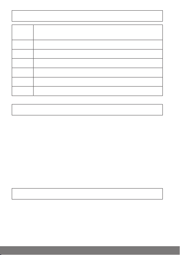
Items included
Quant-
ity
1 Heating actuator RTC3100B
2 Battery LR6 (AA)
3 Adapter
1 Screw M4 x 16 mm
1 Nut M4
1 Assembly and Operating Instructions
Description
Warranty
Structural modifications and incorrect installation which are not in accordance
with these and our other instructions can result in serious injuries, e.g., crushing of limbs. Therefore, structural modifications may only be carried out with
our prior approval and strictly in accordance with our instructions, particularly
the information contained in these Assembly and Operating Instructions.
Any further processing of the products which does not comply with their intended use is not permitted.
The end product manufacturer and fitter have to ensure that all the relevant
current statutory, official and, in particular, EMC regulations are adhered to
during utilisation of our products, especially with regard to end product manufacture, installation and customer advice.
Safety instructions
General information
• Please keep the instruction manual safe!
• Only use in dry rooms.
• Keep children away from control units.
• Observe all pertinent country-specific regulations.
4
Page 5

• Dispose of exhausted batteries properly. Only replace batteries with the
identical type (see Technical data).
• Do not use rechargeable batteries.
Caution
• Device contains small parts that can be swallowed.
Attention
• Ensure that the batteries supply sufficient power to guar-
antee frost protection.
Intended use
The heating actuator described by the present instructions must only be used
for individual room control by means of radiator or underfloor heating in closed
rooms. Only use a CentralControl or a compatible KNX media coupler to control the heating actuator.
• Please note that radio-controlled systems may not be used in areas with
a high risk of interference (e.g., hospitals, airports).
• The remote control is intended solely for use with equipment and sys-
tems in which malfunctions in the hand-held transmitter or receiver
would not pose any risk to persons, animals or property, or which contain
safety devices to eliminate such risks.
• The operator is not protected from interference from other telecommu-
nications systems and terminal equipment (e.g., even from radio-controlled systems which are properly operated in the same frequency
range).
• Only connect radio receivers to devices and systems approved by the
manufacturer.
• Radio-controlled systems transmitting on the same fre-
quency may cause reception interference.
• Note that the range of the radio signal is limited by legis-
lation as well as by design.
5
Page 6
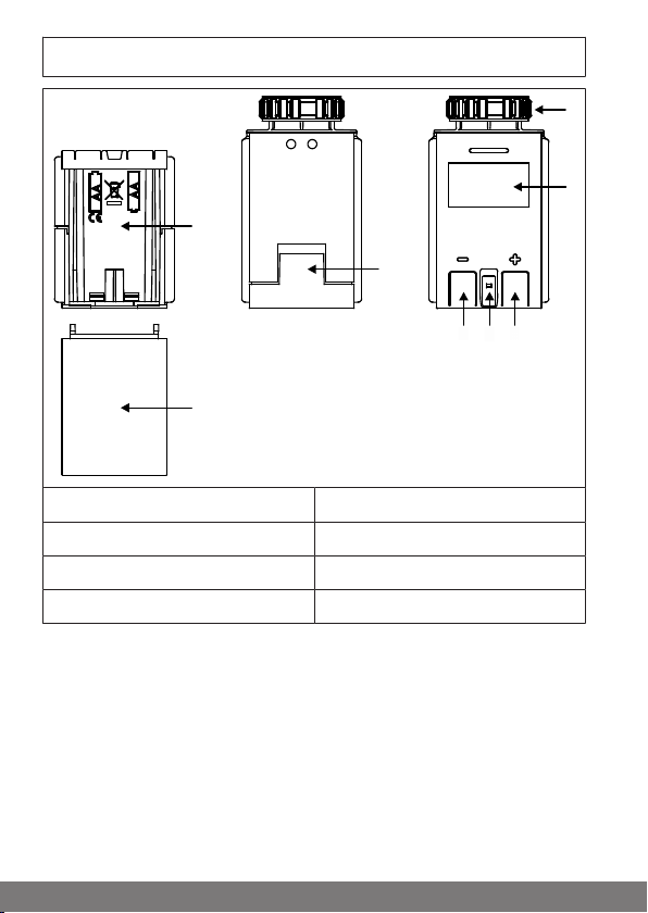
Explanation of displays and buttons
2
1
4
5 3
6
7
8
1. Knurled nut 5. "-" button
2. Display 6. Battery compartment cover lock
3. "+" button 7. Battery compartment
4. Room temperature sensor 8. Battery compartment cover
6
Page 7

1
2
3
4
10
5
6
7
89
1. Programmed heating phases 6. Eco temperature
2. Day of the week 7. Comfort temperature
3. On-site operation disabled 8. Radio connection
4. Battery status
Battery change required (symbol
flashes)
5. Frost protection 10. Status and temperature display
9. Automatic or manual mode active
7
Page 8
Assembly
Assembly can be performed without difficulty on the most common valve
bases with a thread size of M30 x 1.5 mm; no dirt and water stains, as the
heating water circuit is not interrupted.
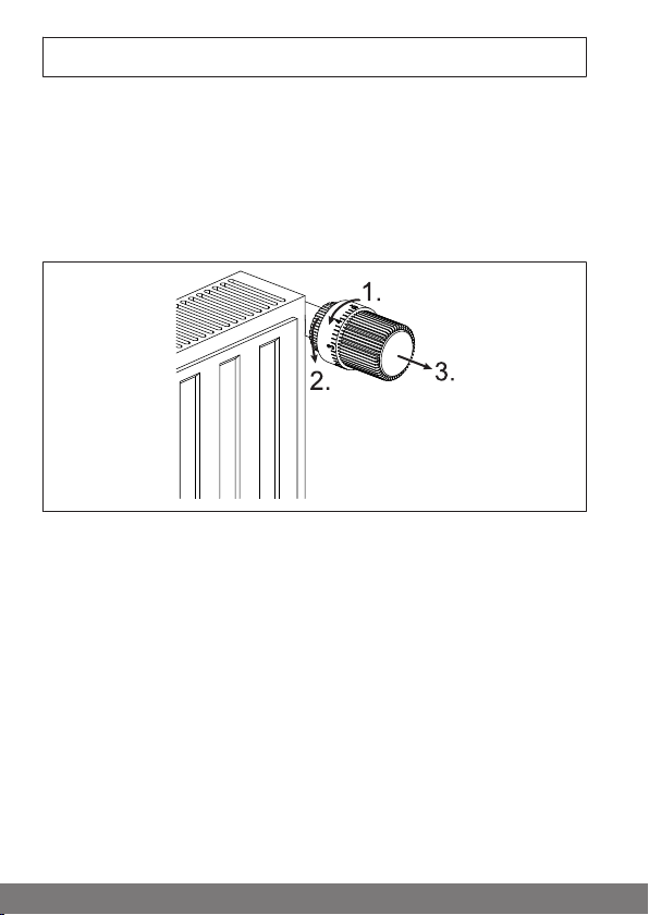
Removing the old radiator thermostat
1. Turn the old thermostat head until it is fully open.
2. Now undo the fastening.
3. Finally, pull the thermostat off the valve.
8
Page 9

Assembly without adapter
View Use Adapter
Heimeier, Junkers Landys
+Gyr, MNG, HoneywellBraukmann
Thread size from M30x1.5
1. Insert the batteries.
2. Wait until the message "LINK" appears on the display for the installation
standby state, or if "OPEN" appears, press the "+" or "-" button until the
message "LINK" appears on the display. The control unit is now in the
program standby state for 15 minutes. For subsequent actions, please
refer to the corresponding operating instructions for the device to be
programmed.
3. After linking successfully, the message "OK" appears on the display,
then changes to "OPEN".
4. Now place the heating actuator on the valve and firmly tighten the
knurled nut (approx. 10 Nm).
5. Now press the "+" and "-" buttons for 5 seconds to allow the heating actuator to re-adapt to the radiator valve. "ADJ" appears on the display.
No ad-
apter re-
quired
9
Page 10

Assembly with the adapter supplied
During installation, make sure that the position of the pins on
the inside of the adapter coincides with the notches on the
Danfoss valve.
View Use Adapter
Danfoss RAV (pin supplied
must be inserted into the
valve tappet)
Danfoss RA Included
Danfoss RAVL Included
Included
10
Page 11

Remove the connectors with black markings completely before mounting
the required adapter.
1. Push the appropriate adapter onto the valve and turn it until it audibly engages. Depending on the adapter, it must be secured with the screw and
nut supplied.
2. Insert the batteries.
3. Wait until the message "LINK" appears on the display for the installation
standby state, or if "OPEN" appears, press the "+" or "-" button until the
message "LINK" appears on the display. The control unit is now in the
program standby state for 15 minutes. For subsequent actions, please
refer to the corresponding operating instructions for the device to be
programmed.
4. After linking successfully, the message "OK" appears on the display,
then changes to "OPEN".
5. Now place the heating actuator on the valve and firmly tighten the
knurled nut.
6. Now press the "+" and "-" buttons for 5 seconds to allow the heating actuator to re-adapt to the radiator valve. "ADJ" appears on the display.
11
Page 12

Waking up the device
To wake up the device, press the "+" or "-" button until the display switches on
automatically. The current mode appears on the display and changes to the
setpoint temperature, or COLD or WINDOW if active.
Disassembly
1. To wake up the device, press the "+" or "-" button until the display
switches on automatically.
2. Press the "+" and "-" buttons simultaneously until the message "LINK"
appears on the display for the program standby state. When the "+" or "-"
button is pressed again, the message "OPEN" appears on the display for
the installation standby state. Wait until the installation run is complete.
3. Now undo the knurled nut and pull the heating actuator off the adapter/
valve.
Cancelling the installation standby state
Press the buttons "+" and "-" for 5 seconds.
12
Page 13

AUTO/MANUAL changeover
The heating plan transferred by the CentralControl is executed in "AUTO" mode. The heating plan transferred by the
CentralControl is not executed and displayed in "MANUAL"
mode.
To wake up the device, press the "+" or "-" button until the display switches on
automatically.
Press the "+" button until the changeover has been implemented on the display.
Manual operation
To wake up the device, press the "+" or "-" button until the display switches on
automatically.
You can increase or reduce the temperature manually (in 0.5°C increments respectively) using the "+" or "–" button.
Tap the "+" or "-" button twice to change the setpoint temperature directly
(schedule-independent) to the Comfort or Eco temperature.
To change the mode from "AUTO" to "MANU" or from "MANU" to "AUTO", tap
the "+" button for longer.
If "AUTO" flashes in the display, the temperature has been changed manually.
This setting is only applied until the next switching time and then reverts to the
preset value.
13
Page 14

Establishing the program/clear standby
state
1. To wake up the device, press the "+" or "-" button until the display
switches on automatically.
2. Press the "+" and "-" buttons simultaneously until the message "LINK"
appears on the display for the program standby state. When the "+" or "-"
button is pressed again, the message "UN-LINK" appears on the display
for the clear standby state.
3. The control unit is now in the program/clear standby state for 3 minutes.
For subsequent actions, please refer to the corresponding operating instructions for the device to be programmed.
For information on configuring the heating actuator using the CentralControl,
refer to our homepage:
https://www.becker-antriebe.de/produktuebersicht/hausautomatisierungcentralcontrol.html
Cancelling the program/clear standby state
Press the "+" and "-" buttons for 5 seconds.
If the heating actuator is at the limit of the radio range, detach the heating actuator and put it into the program/clear
standby state within close range of the CentralControl. You
should then test the heating actuator locally using the CentralControl to make sure it is working.
There may be a delay of up to 90 seconds before the settings
from the CentralControl arrive at the heating actuator.
Window function
If you open a window and the temperature drops significantly as a result, the
heating actuator closes the valve for 10 minutes to save energy. The message
"WINDOW" appears on the display. You cannot make any settings during this
time.
You can cancel the window function by pressing the "+" button for two
seconds.
14
Page 15

Limescale protection function
To prevent calcification of the radiator valves, the heating actuator always runs
the limescale protection function on Saturdays at 12 o'clock.
Frost protection function
If the temperature falls below 4°C, the heating actuator opens the valve until a
temperature of 4°C is maintained. This prevents freezing of the heating appliance.
Switching battery economy mode on/off
To wake up the device, press the "+" or "-" button until the display switches on
automatically.
Switching on
Press the "-" button until the message "COLD" appears on the display.
Switching off
Press the "-" button until the temperature is indicated on the display.
On-site operation disabled
You can only disable and re-enable the heating actuator via the control unit.
For the setting, please refer to the operating instructions for the operator unit.
If on-site operation is disabled, this is indicated by the symbol in the display.
This can only be enabled automatically if the operator unit has not communicated with the heating actuator for at least 1 hour.
15
Page 16

Info
In Info mode, information is provided in the following order:
Day – Time – Software version – KNX software version – Battery voltage
Example:
DI – 13H29 – ST 1-13 – KNX 2-02 – BATT 3-23V
You can access "INFO" mode as follows:
1. To wake up the device, press the "+" or "-" button until the display
switches on automatically.
2. Press the "+" and "-" buttons simultaneously until the message "LINK"
appears on the display for the program standby state.
3. Press the "+" or "-" button until the message "INFO" appears on the display.
The "INFO" mode can be cancelled by changing to a different mode by briefly
pressing the "+" or "-" button. If no button is pressed, the device attempts to
re-adapt itself after 3 minutes and then reverts to the operating status.
Restoring to factory settings
Before resetting the device to factory settings, you must
clear it in all operator units.
1. Remove all batteries (see chapter Changing batteries [}17]) and reinsert them shortly afterwards, then wait until the message "LINK" or
"OPEN" appears on the display.
2. Press and hold the "+" and "-" buttons simultaneously until the message
"ADJ" appears on the display. The heating actuator adapts itself and
changes to normal mode.
3. Press and hold the "+" and "-" buttons simultaneously until the message
"OPEN" or "LINK" appears on the display and the control unit has counted down from 10 to 0.
4. "----" now appears on the display.
5. You can now release the "+" and "-" buttons.
6. The factory setting for the control unit has now been restored.
16
Page 17

Configuration with the CentralControl
For information on configuring the heating actuator using the CentralControl,
refer to our homepage:
https://www.becker-antriebe.de/produktuebersicht/hausautomatisierungcentralcontrol.html
Changing batteries
Attention
Do not use rechargeable batteries.
Do not use used and new batteries together.
You will find the appropriate battery type in the "Technical
data" chapter.
1. Open the battery compartment.
2. Take out the batteries.
3. Insert the new batteries correctly.
4. Close the battery compartment.
5. "OPEN" appears on the display.
6. Now press the "+" and "-" buttons to allow the heating actuator to re-adapt to the radiator valve. "ADJ" appears on the display.
The date and time is updated automatically via the operator unit.
The saved values are retained.
17
Page 18

Cleaning
Only clean the device with a suitable cloth. Do not use aggressive cleaning
agents that may damage the surface.
Technical data
Rated voltage 3 V DC
Battery type LR 6 (AA)
Degree of protection IP20
Permissible ambient temperature 0°C to +50°C
Maximum emitted transmission output ≤ 25 mW
Radio frequency 868.3 MHz
Max. actuating force 120N
Max. media temperature 100°C
Max. valve lift 4.5 mm
Actuating time Approx. 3 s/mm
Dimensions (WxHxD) 65 x 65 x 48 mm
Wiring M30 x 1.5
The maximum transmitter range on and in the building is up to 25m, and up to
350m in the open.
18
Page 19

What to do if...?
Problem Solution
The heating actuator does not open
or close the valve automatically.
Nothing appears on the display. Briefly press any button.
The heating actuator is not controlling the temperature as required.
The heating actuator is not controlling according to the required
times.
The heating actuator is controlling
outside the defined times.
The error code ERR0 appears on the
display
The error code ERR1 appears on the
display
Bring the operator unit within range
of the heating actuator.
Insert batteries correctly or insert
new batteries.
Insert batteries correctly or insert
new batteries.
Check the setting at the operator
unit.
Tighten the heating actuator handtight.
Use the correct adapter.
Mount the adapter correctly.
Check the setting at the operator
unit.
Descaling function active.
Assembly error
Make sure that coupling ring and
heating actuator are seated correctly.
Temperature sensor error
The device is defective and must be
replaced.
19
Page 20

Problem Solution
The error code ERR2 appears on the
display
On-site operation is not possible. Remove the on-site operation block
Programming/clearing process in
the CentralControl has failed. Start
the process at the heating actuator
by pressing a button again, and in
the CentralControl.
at the operator unit.
Simplified EU declaration of conformity
Becker-Antriebe GmbH hereby declares that this radio control system complies with Directive 2014/53/EU.
The full text of the EU declaration of conformity is available at the following
web address:
www.becker-antriebe.com/ce
Subject to technical changes without notice.
202122
Page 21

Page 22

Page 23

23
Page 24

 Loading...