

Page 1

Remote-Controlled
Installatio n and Operation
Manual DV17501.03
VHF-AM Transceiver
RT6512
Issue 06 April 2018
Article-No. 0645.702-071
Becker Avionics GmbH • Baden-Airpark B108 • 77836 Rheinmünster • Germany
+49 (0) 7229 / 305-0 • Fax +49 (0) 7229 / 305-217
http://www.becker-avionics.com • E-mail: info@becker-avionics.com
Page 2
Installation and Operation
Becker Avionics
Contact Data for
America, Australia, Japan
Approved Production and Maintenance Organization
Certificates see: http://www.becker-avionics.com/company-about/ →Certificates
Germany: Becker Avionics GmbH
Baden-Airpark B108
77836 Rheinmünster (Germany)
Tel.: + 49 (0) 7229 / 305-0
Fax: + 49 (0) 7229 / 305-217
Internet: www.becker -avionics.com
Email: info@becker-avionics.com
Sales:
Email: sales@becker-avionics.com,
Customer Service:
Email: support@becker-avionics.com
Email: info@beckerusa.com
WARNING - USER RESPONSIBILITY
FAILURE OR IMPROPER SELECTION OR IMPROPER USE OF THE PRODUCTS DESCRIBED
HEREIN OR RELATED ITEMS CAN CAUSE DEATH, PERSONAL INJURY AND PROPERTY
DAMAGE.
• This document and other information from Becker Avionics GmbH provide product or system
options for further investigation by users having technical knowledge.
• The user is responsible for making the final selection of the system and components. The user
has to assure that all performance, endurance, maintenance, safety requirements of the
application are met and warnings be observed.
For this the user has to include all aspects of the application to be compliant with the applicable
industry standards and the requirements of the responsible aviation authority. The product
documentations from Becker Avionics GmbH have to be observed.
• To the extent that Becker Avionics GmbH provide component or system options based upon data
or specifications provided by the user, the user is responsible for determining that such data and
specifications are suitable and sufficient for all applications and reasonably foreseeable uses of
the components or systems.
Term definition: User in the sense of user, installer, installation company.
2 RT6512 DV17501.03 Issue 06 April 2018
Page 3
Becker Avionics
Installation and Operation
Preface
Remote
Dear Customer,
Thank you for purchasing a Becker Avionics product. We are pleased that you have chosen our
product and we are confident that it will meet your expectations.
For development of our products, the gui delines for highes t quality and reliab ility have been borne in
mind, supplemented by selection of high quality material, responsible production and testing in
accordance to the corresponding standards.
Our competent customer support department will respond on any technical question you may have.
Please do not hesitate to contact us at any time.
-Controlled VHF-AM Transceiver
DV17501.03 Issue 06 April 2018 RT6512 3
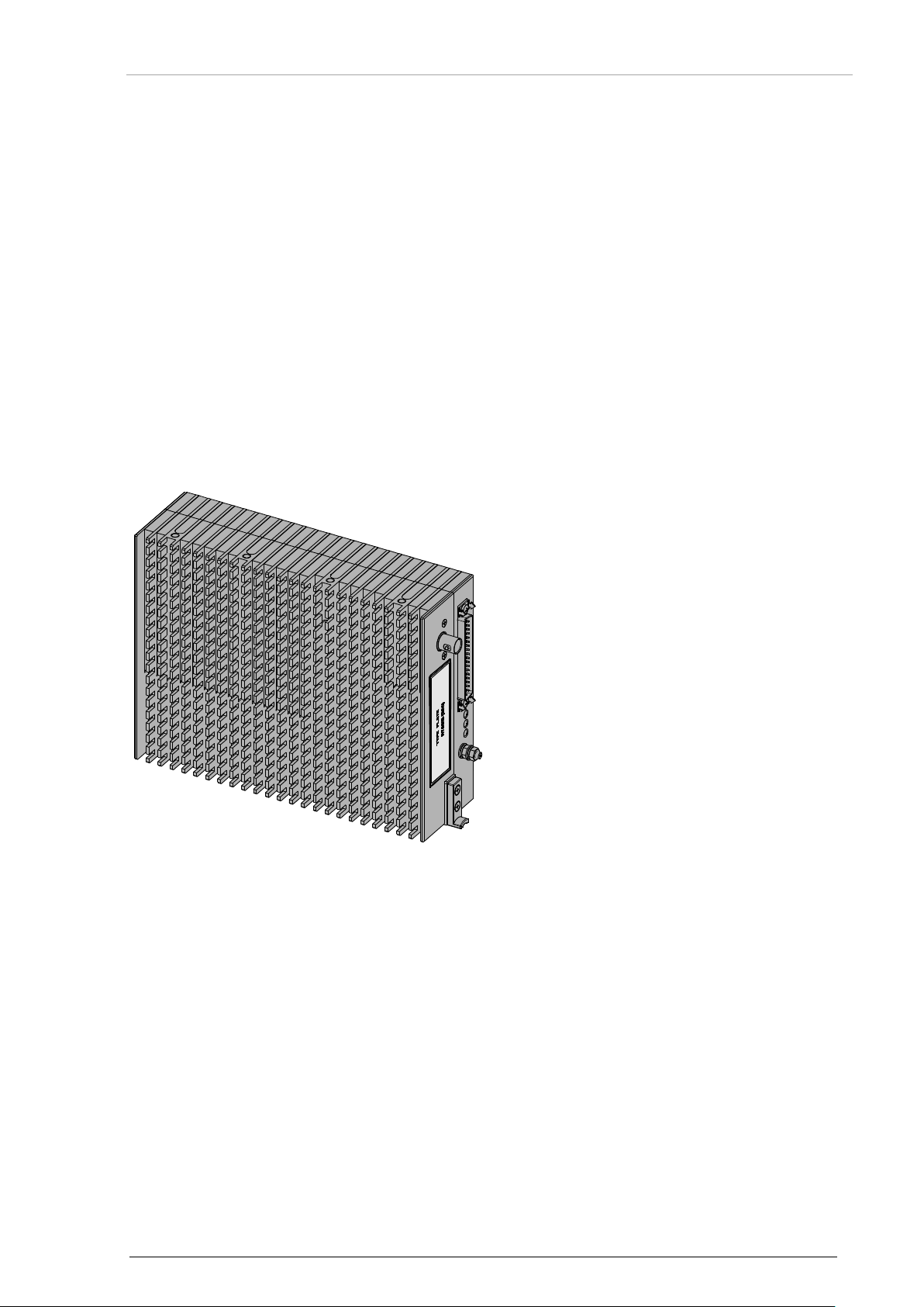
RT6512 (Remote Transceiver)
without mounting tray
Page 4

Installation and Operation
Becker Avionics
List of Effective Pages and Changes
Only technical relevant modifications are described in this table.
Document: DV17501.03 / issue 06 Article Number 0645.702-071
Cover Page 04/2018
Introduction 04/2018
Chapter 1 – 4 04/2018
Issue Page No.:
06
1-60 all Changed: Editorial adjustments.
-- all Added: Descriptions about RCU6512.
--
--
---
--
--
--
--
--
Section /
Chapter
Description
--
--
--
--
--
© by Becker Avionics GmbH / all rights reserved
4 RT6512 DV17501.03 Issue 06 April 2018
Page 5
Becker Avionics
Installation and Operation
Table of Contents
1 General Description .................................................................................................................... 11
1.1 Introduction.................................................................................................................................. 12
1.2 Purpose of Equipment ................................................................................................................. 13
1.3 Variants Overview ....................................................................................................................... 14
1.4 Associated Device s ..................................................................................................................... 14
1.5 Scope of Functionality ................................................................................................................. 15
Receive Mode ................................................................................................................... 15
Transmit Mode .................................................................................................................. 15
Emergency Mode .............................................................................................................. 15
Audio Inputs and Outputs ................................................................................................. 16
1.5.4.1 Microphone Input ......................................................................................................... 16
1.5.4.2 Audio Input LINE IN ..................................................................................................... 16
1.5.4.3 Audio Output LINE OUT .............................................................................................. 17
Control Inputs .................................................................................................................... 17
1.5.5.1 /ON (Unit Power ON/OFF Control) .............................................................................. 17
1.5.5.2 /PTT (Push-To-Talk) .................................................................................................... 17
1.5.5.3 /COM2 (Com Addressing Line) ................................................................................... 17
1.5.5.4 /SEL422 (Serial Interface Selection Line).................................................................... 17
1.5.5.5 /RX_ATT (External RX Attenuation Control) ............................................................... 18
1.5.5.6 /SERV_EN (Enabling the Setup Modes) ..................................................................... 18
1.5.5.7 /TX-ENABLE (Enabling the TX) ................................................................................... 18
1.5.5.8 /EMERG (Enabling the Emergency Mode) .................................................................. 18
Status and Control Outputs .............................................................................................. 19
1.5.6.1 /FAILURE ..................................................................................................................... 19
1.5.6.2 RX_AGC (AGC Voltage of the RX-RF-AGC) .............................................................. 19
1.5.6.3 /SQL_EVAL ................................................................................................................. 19
Digital Interfaces to the Control Unit ................................................................................. 20
1.5.7.1 Interface ARINC 429 .................................................................................................... 20
1.5.7.2 Interface RS422 ........................................................................................................... 20
1.6 Safety-Conscious Utilization ....................................................................................................... 20
1.7 Restriction for Use ....................................................................................................................... 21
1.8 Technical Data ............................................................................................................................ 22
General Characteristics .................................................................................................... 22
Typical Power Consumption ............................................................................................. 22
Receiver Data ................................................................................................................... 23
Transmitter Data ............................................................................................................... 24
Dimensions & Weight........................................................................................................ 24
Software ............................................................................................................................ 25
Hardware .......................................................................................................................... 25
Continued Airworthi nes s ................................................................................................... 25
Environmental Conditions ................................................................................................. 26
Certifications ..................................................................................................................... 27
1.8.10.1 RT6512 meets the Requirements of: ........................................................................... 27
1.8.10.2 Guidelines followed for Design and Development ....................................................... 27
1.8.10.3 FCC Approval .............................................................................................................. 28
1.9 Order Code.................................................................................................................................. 29
RT6512 ............................................................................................................................. 29
Accessories ....................................................................................................................... 29
2 Installation .................................................................................................................................... 31
2.1 Packaging, Transport, Storage ................................................................................................... 31
2.2 Device Assignment ..................................................................................................................... 32
Scope of Delivery .............................................................................................................. 32
Additional Required Equipment (optional) ........................................................................ 32
Type Plate ......................................................................................................................... 33
Meaning of Status LEDs ................................................................................................... 33
2.3 Mounting Requirements .............................................................................................................. 34
Mounting Distance ............................................................................................................ 34
Grounding ......................................................................................................................... 34
Antenna Cables ................................................................................................................ 35
2.3.3.1 Attenuation: Cable length versus coax cable type ...................................................... 35
Antenna Installation .......................................................................................................... 36
DV17501.03 Issue 06 April 2018 RT6512 5
Page 6
Installation and Operation
Becker Avionics
2.3.4.1 Required Antenna Type ............................................................................................... 36
2.3.4.2 Antenna Mounting Location ......................................................................................... 36
2.3.4.3 Recommendation for Installation of two RT6512 in one Aircraft ................................. 38
2.3.4.4 Radio Setting and Wiring for dual installation .............................................................. 38
2.4 Dimensions .................................................................................................................................. 39
RT6512 .............................................................................................................................. 39
RT6512 with Mounting Tray MT6512 ................................................................................ 40
2.5 Connector Pin Assignments ........................................................................................................ 41
Connector P1 (RT6512) .................................................................................................... 41
2.6 Equipment Configuration Samples .............................................................................................. 43
RT6512 with RCU6512 ..................................................................................................... 43
RT6512 with RMU5000 ..................................................................................................... 43
RT6512 with ARINC 429 Controller .................................................................................. 43
2.7 Aircraft Wiring .............................................................................................................................. 44
RT6512-(XX0) with RCU6512 as Primary Controller ........................................................ 45
RT6512-(XX0) with ARINC 429 Controller ........................................................................ 46
RT6512-(XX1) with ARINC 429 Controller ........................................................................ 47
2.8 Post Installation Tests ................................................................................................................. 48
Mechanical Installation and Wiring Check ........................................................................ 48
Power Supply .................................................................................................................... 48
Receiver / Transmitter Operation ...................................................................................... 48
Antenna Check .................................................................................................................. 48
Interference Check ............................................................................................................ 48
Flight Test Check .............................................................................................................. 50
3 Operating Instructions ................................................................................................................ 51
3.1 Device Description....................................................................................................................... 51
Device Assignment ........................................................................................................... 51
3.2 Operating with RCU6512 ............................................................................................................ 51
3.3 Operating with RMU5000 ............................................................................................................ 51
3.4 Operating with OEM Controller ................................................................................................... 51
3.5 Start-Up ....................................................................................................................................... 52
Built In Tests (BIT) ............................................................................................................ 52
3.5.1.1 Initiated Built In Test (IBIT) .......................................................................................... 54
3.5.1.2 Power On Built In Test (PBIT) ...................................................................................... 54
3.5.1.3 Continuous Built In Test (CBIT) ................................................................................... 54
3.5.1.4 Error Indication ............................................................................................................. 55
3.6 RS422 Protocol supported by RT6512 ....................................................................................... 57
3.7 ARINC 429 Protocol supported by RT6512 ................................................................................ 57
3.8 Contact Data ................................................................................................................................ 58
4 Index .............................................................................................................................................. 60
List of Figures
Figure 1: Standard Microphone Input Schematic ................................................................................................... 16
Figure 2: LINE_IN Schematic ................................................................................................................................. 16
Figure 3: LINE_OUT .............................................................................................................................................. 17
Figure 4: /FAILURE Output Schematic .................................................................................................................. 19
Figure 5: Type Plate (Example) .............................................................................................................................. 33
Figure 6: RT6512 with MT6512 - mounting area .................................................................................................... 34
Figure 7: Antenna Installation ................................................................................................................................. 36
Figure 8: RT6512 Dimensions (without and with Main Connector applied) ............................................................ 39
Figure 9: RT6512 with Mounting Tray MT6512 ...................................................................................................... 40
Figure 10: RT6512 with RCU6512 ......................................................................................................................... 43
Figure 11: RT6512 with RMU5000 ......................................................................................................................... 43
Figure 12: RT6512 with ARINC 429 Controller ...................................................................................................... 43
Figure 13: RT6512-(XX0) with RCU6512 as Primary Controller ............................................................................ 45
Figure 14: RT6512-(XX0) with ARINC 429 Controller ............................................................................................ 46
Figure 15: RT6512-(XX1) with ARINC 429 Controller ............................................................................................ 47
Figure 16: Thermal Behavior for TX Function ........................................................................................................ 53
6 RT6512 DV17501.03 Issue 06 April 2018
Page 7

Becker Avionics
Installation and Operation
List of Abbreviations
List of Abbreviations
A3E
Amplitude modulation double-sideband with full carrier
AGC
Automatic Gain Control
AM
Amplitude Modulation
AOC
Air Operations Centre
ARINC
Aeronautical Radio Incorporated
ARINC 429
Data bus for commercial aircraft
ATS
Air Traffic Services
BIT
Built In Test
BNC
Bayonet Neill Concelman (connector)
CBIT
Continuous Built In Test
CU
Control Unit
DAL
Design Assurance Level
DC
Direct Current
EUROCAE
European Organization for Civil Aviation Equipment
EASA
European Aviation Safety Agency
FAA
Federal Aviation Administration
IBIT
Initiated Built In Test
n/a
not applicable
LED
Light Emitting Diode
OEM
Original Equipment Manufacturer
PBIT
Power On Built In Test
PSB
Power Supply Board
PTT
Push To Talk
RCU
Remote Control Unit
RMU
Radio Management Unit
RX
Receiver
Std
Standard
TX
Transmitter
VDC
Volts Direct Current
VHF
Very High Frequency
VSWR
Voltage Standing Wave Ratio
TufLok®
Registered trademark. Thread loc kin g patch
ELASTOSIL®
Registered trademark. Silicon produ cts.
DV17501.03 Issue 06 April 2018 RT6512 7
Page 8
Installation and Operation
Becker Avionics
Units
A
Ampere
mA
Milliampere
°C
Degree Celsius
dBm
Power ratio in Decibel referenced to 1 mW
dB
Decibel
ft
Foot
g
Gram
in
Inch
kHz
Kilohertz
MHz
Megahertz
mm
Millimeter
NM
Nautical Mile
kΩ
Resistance kilo Ohm
Ohm (Ω)
Resistance
ppm
Part per million
s
Second
V
Volt
mV
Millivolt
W
Watt
mW
Milliwatt
Indicates a hazardous situation which, if not avoided, will result in death or serious
Indicates a hazardous situation which, if not avoided, could result in death or
Indicates a hazardous situation which, if not avoided, could result in minor or
Is used to address practices not related to physical injury.
Safety instructions (or equivalent) signs indicate specific safety-related
Units
General Safety Instructions
injury.
serious injury.
moderate injury.
instructions or procedures.
8 RT6512 DV17501.03 Issue 06 April 2018
Page 9
Becker Avionics
Installation and Operation
Disposal
The packaging material is inflammable, if it is disposed of improperly by
The device(s) may be installed on an aircraft only by an approved aeronautical
The user is responsible for a safe installation and/or additional safety measures
burning, toxic fumes may develop.
This product contains materials that fall under the special disposal regulation, which corresponds to
the EC directive for dangerous disposal material. We recommend disposing of the respective materials
in accordance with the respectively valid environmental laws.
• Dispose circuit boards via a technical waste dump which is allowed to take on e.g.
electrolytic aluminium capacitors. Do under no circumstances dump the circuit boards with
normal waste dump.
Warranty Conditions
company (e.g. EASA Part 145) which shall also examine and verify the
User conversions and changes are not permitted.
Any change on the product, made by the user, excludes any liability of Becker Avionics GmbH.
• For installation, opening the device is not required.
• Do not make any modifications to the device, except for those described in the manual.
• Make connections to the inputs, outputs and interfaces only in the manner described in
the manual.
• Install the devices according to the instructions.
We cannot provide any guarantee for other mounting methods.
installation.
Conditions of Utilization
General introductory notes
With this device you b ought a product, which was manufactured and tested before delivery with th e
utmost care.
Please take your t ime to read the f ollowing notes, whic h you should follo w closely during insta llation
and operation.
Otherwise, all claims under the warranty will become void an d a reduced service life or even parti al
damage is not excludable.
in order to prevent damages to persons or the electric installations of the
airplane. In case of deviations to the descriptions in this document perform all
work in accordance with the airplane service manual or take the AC43-13, in its
latest revision, into account.
Additional Conditions of Utilization
Please refer to "Safety-Conscious Utilization", page 20.
Non-Warranty Clause
We checked the co nte nts o f this publication for com pli ance with the associat ed h ard a nd s of tware. We
can however, not exclude discrepancies and do therefore not accept any liability for the exact
compliance. The inf ormation in this public at ion is u nde r goin g a regularly review, necessary correc tio ns
will be part of the subsequent issues of this publication.
DV17501.03 Issue 06 April 2018 RT6512 9
Page 10

Installation and Operation
Becker Avionics
Blank Page
10 RT6512 DV17501.03 Issue 06 April 2018
Page 11

Becker Avionics
General Description
Introduction
1 General Description
In this chapter you can read about:
1.1 Introduction.................................................................................................................................. 12
1.2 Purpose of Equipment ................................................................................................................. 13
1.3 Variants Overview ....................................................................................................................... 14
1.4 Associated Devices ..................................................................................................................... 14
1.5 Scope of Functionality ................................................................................................................. 15
Receive Mode ................................................................................................................... 15
Transmit Mode .................................................................................................................. 15
Emergency Mode .............................................................................................................. 15
Audio Inputs and Outputs ................................................................................................. 16
Control Inputs .................................................................................................................... 17
Status and Control Outputs .............................................................................................. 19
Digital Interfaces to the Control Unit ................................................................................. 20
1.6 Safety-Conscious Utilization ....................................................................................................... 20
1.7 Restriction for Use ....................................................................................................................... 21
1.8 Technical Data ............................................................................................................................ 22
General Characteristics .................................................................................................... 22
Typical Power Consumption ............................................................................................. 22
Receiver Data ................................................................................................................... 23
Transmitter Data ............................................................................................................... 24
Dimensions & Weight........................................................................................................ 24
Software ............................................................................................................................ 25
Hardware .......................................................................................................................... 25
Continued Airworthi nes s ................................................................................................... 25
Environmental Conditions ................................................................................................. 26
Certifications ..................................................................................................................... 27
1.9 Order Code.................................................................................................................................. 29
RT6512 ............................................................................................................................. 29
Accessories ....................................................................................................................... 29
This manual describes the Becker Avionics remote-controlled VHF-AM transceiver RT6512-(XXX).
The t ype plate on your device shows the part number for identification purposes (see "T ype Plate",
page 33).
Before starting operati on of the device(s) please read t his manual c arefull y, with particul ar attention t o
the description referring to your device(s).
DV17501.03 Issue 06 April 2018 RT6512 11
Page 12

General Description
Becker Avionics
Introduction
1.1 Introduction
The technical information in this document applies to the described product(s) RT6512-(XXX). For
further descriptions we are using the term RT6512 instead writing the complete model number.
If a description ref ers to only one of the product var iants its full nam e, e.g. "RT6512-(100)", will be
used.
The manuals Maintenance & Repair (M&R) and Installation & Operation (I&O) contain the following
sections:
Section
DV 17501.04
M&R
DV 17501.03
I&O
General Description X X
Installation X X
Operation Instructions X X
Theory of Operation X N/A
Maintenance and Repair X N/A
Illustrated Parts List X N/A
Modification and Changes X N/A
Circuit Diagrams X N/A
Certifications X N/A
Attachments X N/A
12 RT6512 DV17501.03 Issue 06 April 2018
Page 13

Becker Avionics
General Description
Purpose of Equipment
1.2 Purpose of Equipment
The mechanical design of the remote-controlled VHF-AM transceiver RT6512 is rugge dized and well
suited for installati on in the av ion ics c ompartment (non-press ur ized a nd not temperature control led) by
means of a mounting tra y and in all types of aircraft.
The remote-controlled VHF-AM transceiver RT6512 meets RTCA and EUROCAE airworthiness
requirements applicable at the time the unit received certification. There are no restrictions for
installation of the u nit as long as it w ill be installed in areas, where data of the proven env ironmental
categories will not exceed.
• RT6512 is a simplex vo ice c ommunication system in the standard avionics VHF frequency
range 118.000...136.975 MHz (136.9916 MHz with 8.33 kHz channel spacing) or opti ona l
with extended frequency range up to 155.975 MHz and uses stan dard amplitude
modulation (A3E). RT6512 is capable to operate in both, the 25 or 8.33 kHz channel
spacing is primarily intended for aeronautical operational control (AOC) and air traffic
services (ATS) safety communications.
• RT6512 uses ARINC 429 and RS422 interfaces for communication with a co ntro l dev ice.
• RT6512 provides frequency and mode control, either by means of the Becker RCU6512 or
RMU5000 controller using the RS422 communication port, or by means of any OE
oduct using the standard ARINC 429 communication bus.
pr
• With transmitter power of 20W, RT6512 is able to support simultaneous communication
over a range exceeding 200 NM direct line of sight, within the frequency range.
M
DV17501.03 Issue 06 April 2018 RT6512 13
Page 14
General Description
Becker Avionics
RT
6512
- ( X X X
)
Device
Function/Manufacturer
RCU6512
Becker Avionics Remote Control Unit
RMU5000
Becker Avionics Radio Management Unit
Control unit
Gables G7610 (Control unit for VHF-COMM only)
Control unit
Universal RCU
Glass cockpit
Genesys IDU680
Associated Devices
1.3 Variants Overview
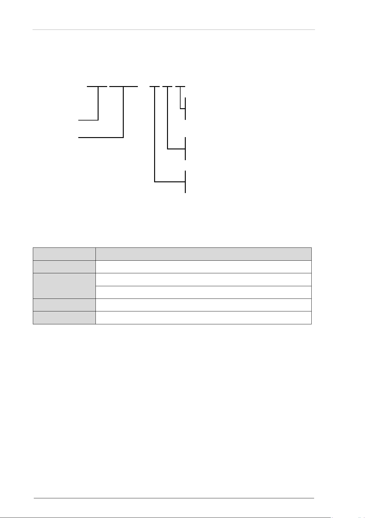
Within the part number, the meaning of "RT6512-(XXX)", is:
Type Identifier
Model Number
1.4 Associated Devices
Following devices can operate with RT6512-(XXX):
0 – Standard
1 – with Emergency Mode
0 - Standard
1 – Std. Freq. Range 118...136.975 MHz
2 – Ext. Freq. Range 118...155.975 MHz
14 RT6512 DV17501.03 Issue 06 April 2018
Page 15

Becker Avionics
General Description
Scope of Functionality
1.5 Scope of Functionality
RT6512 performs AM (amplitude modulation) voice communication.
Mechanics: Case serves as heat sink:
Front side conta ins the main connect or for connection to the aircraft wiri ng system, and the a ntenna
jack. Three front panel LEDs indicate basic information about overall equipment status.
Receive Mode
RT6512 is equipped with a high-quality Class C, E and H2 receiver:
• Standard sensitivity 5 µV, high dynamic range, and high blocking rejection.
• It can receive a weak signal while a 2
transmitting.
• The RT6512 can operate with offset carrier in both 25 kHz and 8.33 kHz channel spacing.
Transmit Mode
RT6512 is equipped with a high-quality Class 3 and 5 transmitter:
• Output power of 20 W under standard operating conditions.
• Output power of at least 16 W under the specified environmental operating conditions
(when using antenna with VSWR≤2:1, for VSWR>3:1 outp ut po wer lowers ).
• AM depth >70% - standard value for airborne application.
• During transmission, the transmitter delivers a natural sidetone signal, which is available
on the LINE_OUT output (if enabled).
• RT6512 is equipped with a protective function to prevent from blocking the frequency
channel by a stuck transmit button or a short circuit on the key line.
• RT6512 provides status information if device is transmitting via serial protocol (RS422 and
ARINC 429). This status can be used to inform the crew about terminated transmission
(as required by TSO-C128a/ETSO-2C128).
• RT6512 transmitter is protected from overheating. VSWR on antenna connector is also
monitored. See "Status and Control Outputs", page 19 for details.
nd
VHF-AM transceiver in the same aircraft is
Emergency Mode
• The RT6512-(201) var ia nt suppor ts Em ergency Mode in which device is automaticall y tuned to
emergency channel 121.500 MHz in 25 kHz channel spacing.
• External control of transceiver is prohibited with remaining device status monitoring.
Note: Operators Remark
121.5 MHz = International voice aeronautical emergency.
123.1 MHz = International worldwide voice SAR use (e.g. Italy).
DV17501.03 Issue 06 April 2018 RT6512 15
Page 16
General Description
Becker Avionics
Scope of Functionality
Audio Inputs and Outputs
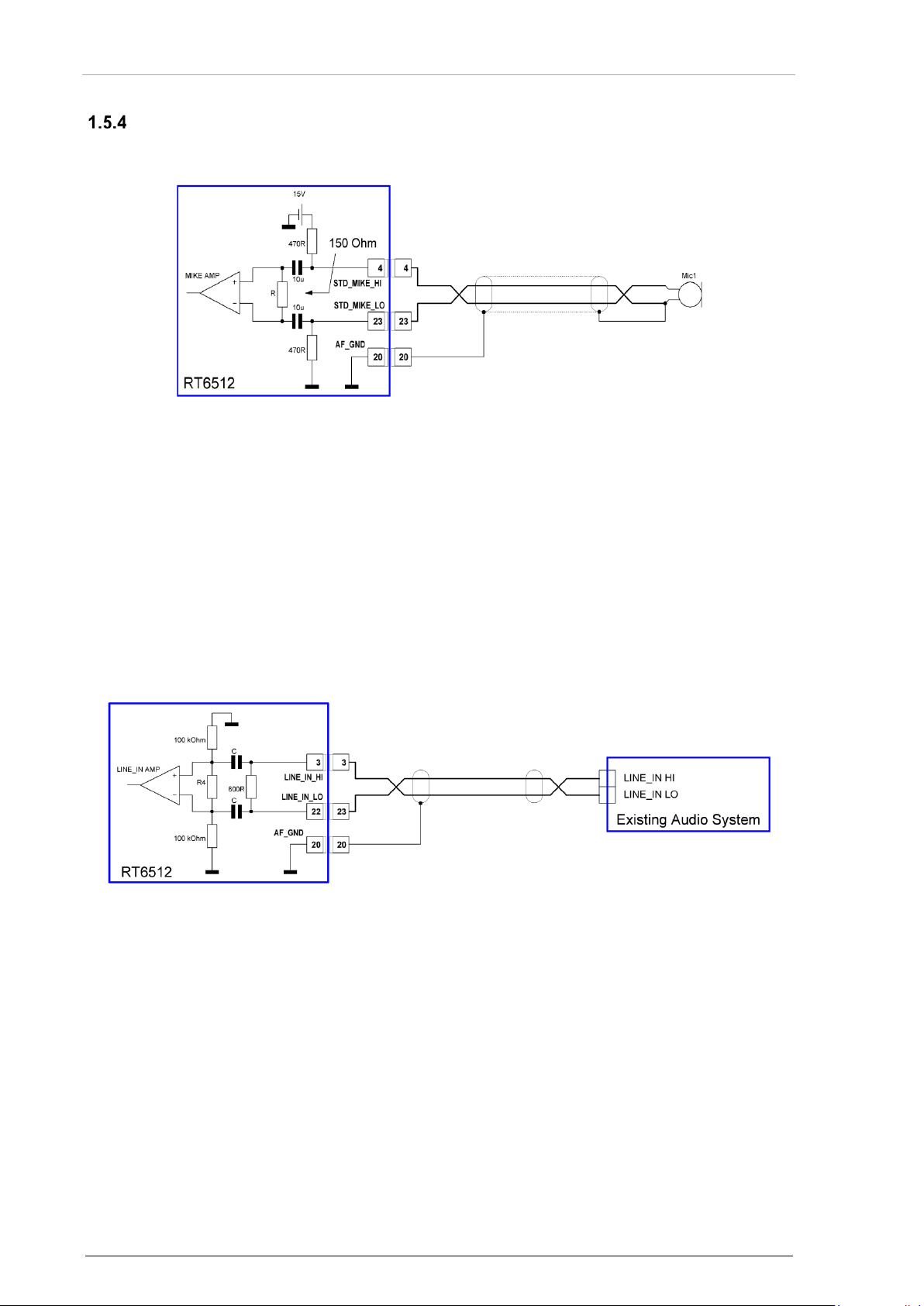
1.5.4.1 Microphone Input
Figure 1: Standard Microphone Input Schematic
RT6512 is designed for a standard microphone:
• Unbalanced,
• DC coupled,
• DC supplied from RT6512.
The bias current for s tandard microphone is drawn from RT6512 internal source 15 VDC via series
resistor 470 Ohm. The inp ut audio signal is routed to a dynamic compressor keeping the modulation
factor limited over a wide input voltage range. T he microphon e input uses the c able guard as ground
compensation so microphone input shall be connected exactly as specified on Installation diagrams.
1.5.4.2 Audio Input LINE IN
The RT6512 symmetr ical line input has no DC co nnection to ground. I nput impedance is 600 Ω. The
maximum input lev el without clipp ing can be set as high as 6 V. The input audio signal is routed to a
dynamic compressor keeping the modulation factor limited over a wide input voltage range.
16 RT6512 DV17501.03 Issue 06 April 2018
Figure 2: LINE_IN Schematic
Page 17
Becker Avionics
General Description
Scope of Functionality
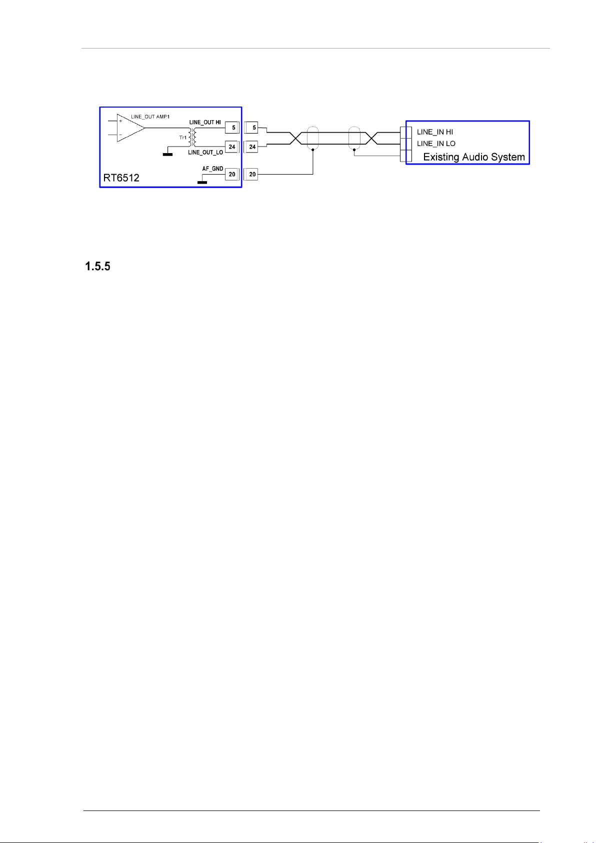
1.5.4.3 Audio Output LINE OUT
Figure 3: LINE_OUT
The audio output LINE OUT design is symmetrical an d has no DC con necti on to gr ound. If volume set
to maximum, the audio output power delivered is 100…125 mW into 600 Ω or 200 mW into 150 Ω.
Control Inputs
1.5.5.1 /ON (Unit Power ON/OFF Control)
/ON signal to switch ON/OFF the RT6512.
The /ON line is used to activate an internal electronic switch to power-up the unit.
It is active if the level on th e /ON pin is less than 4.0 V or a resistance of less than 1 kΩ connects to
ground.
The /ON line is inactive if the level on the /ON pin is higher than 8.0 V or a resistance higher
than 50 kΩ connects to ground.
1.5.5.2 /PTT (Push-To-Talk)
/PTT is used to initiate transmission.
It is active when /PTT-input level is below 4.0 V, or a resistance to ground of less than 1 kΩ.
The /PTT line is inactive if the level on the /PTT-input is higher than 8.0 V, or a resistance higher
than 50 kΩ connects to ground.
1.5.5.3 /COM2 (Com Addressing Line)
/COM2 defines device sub address for ARINC communication.
The device detects a LOW state (Active state) on the /COM2 input when an external resistance of
lower than 1 kΩ is connected to ground.
The device detects a HIG H state (Inactive state) on the /CO M2 input when an external res istance of
higher than 50 kΩ is connected to ground.
• Com addressing line bit:
o LOW (Active) state selects COM2.
o HIGH (Inactive) state selects COM1.
1.5.5.4 /SEL422 (Serial Interface Selection Line)
/SEL422 selects RS422 or ARINC 429 communication.
The device detects a LOW state (Active state) on the /SEL422 input when an external resistance of
lower than 1 kΩ is connected to ground.
The device detects a HIGH state on the /SEL422 input when an external resistance of higher
than 50 kΩ is connected to ground.
• Serial interface selecti on line:
o LOW (Active) state selects RS422.
o HIGH (Inactive) state selects ARINC.
DV17501.03 Issue 06 April 2018 RT6512 17
Page 18

General Description
Becker Avionics
For an aircraft installation /TX-ENAB L E input shall be connected to ground
Scope of Functionality
1.5.5.5 /RX_ATT (External RX Attenuation Control)
/RX_ATT reduces the RF gain of the RX section to reduce cross talk effects.
The /RX_ATT line is us ed for an optiona l desensitizati on of the RT6512 rec eiver. The des ensitization
nd
can be required wh en a 2
st
line from 1
VHF-AM trans c eiv er s ha ll be connected to /RX _ AT T input of 2nd device and / PT T from 2nd
device shall be connected to /RX_ATT input of the 1
VHF-AM transc eiver i n th e s ame aircraft is transm ittin g. In s uch c as e / PT T
st
device.
The /RX_ATT is active if /RX_ATT-input level is less than 4.0 V, or a resistance less than 1 kΩ
connects to ground.
The /RX_ATT line is inac tive if the level on the /RX_ATT -input is higher than 8.0 V, or a resistance
higher than 50 kΩ connects to ground.
1.5.5.6 /SERV_EN (Enabling the Setup Modes)
/SERV_EN enables the setup modes.
/SERV_EN is a read/write access for all setup data, not available for standard user
The device detects a LOW state (Active sta te) on the /SER V_EN input when an e xter nal res istance of
lower than 1 kΩ is connected to ground.
The device detects a HIGH state ( Inactive s tate) on the / SERV_EN input when an ex ternal r esistanc e
of higher than 50 kΩ is connected to ground.
1.5.5.7 /TX-ENABLE (Enabling the TX)
/TX-ENABLE enables the transmitter.
RT6512 detects a low state on the /TX_ENABLE in put when an external resist ance lower than 1 kΩ
connects to ground.
RT6512 is detecting high state on the /TX_ENABLE input when an external resistance higher
than 50 kΩ connects to ground. In such case transmission is permanently blocked.
directly on the main connector. / TX-ENABLE line cannot be routed as part
of installation cable bundle.
Note: Do not apply DC voltage above 5 Volts to /TX_ENABLE to avoid
device damage!
1.5.5.8 /EMERG (Enabling the Emergency Mode)
/EMERG enables the Emergency Mode for variant –(201) only.
RT6512-(201) detects a low stat e on the /EMERG in put when an external r esistance lower tha n 1 kΩ
connects to ground. In such case transceiver activates Emergency Mode operation.
RT6512-(201) is detecting high state on the /EMERG input when an external resistance higher
than 50 kΩ connects to ground.
18 RT6512 DV17501.03 Issue 06 April 2018
Page 19

Becker Avionics
General Description
Scope of Functionality
Status and Control Outputs
1.5.6.1 /FAILURE
Figure 4: /FAILURE Output Schematic
This /FAILURE output is coupled to the status shown at th e status LEDs mounted at the connec tor
side of RT6512. It corresponds to OR function of the r ed and the yellow LEDs. When the test func tion
is not ok, the transistor in the /FAILURE output is ON.
This output is an open collector (drain) type with capability to:
• Draw maximum 100 mA current to ground with a voltage drop of less than 2.5 V
(corresponding LEDs is on),
• Draw maximum 0.1 mA current to ground for output voltage 28.0 V when in "inactive" state
(corresponding LEDs are off).
It can be used to dr ive an external relay if 100 mA output current limit at t he supply voltag e 28.0 V is
not sufficient. This /FAILU RE output is protec ted against spikes produced f rom a relay. See "Status &
Error Indication", page 55.
1.5.6.2 RX_AGC (AGC Voltage of the RX-RF-AGC)
The AGC output is a DC coupled output of the RF-AGC used in the receiver.
The output voltage v aries monotonic within the ra nge of 0...5 V, when the i nput level at the antenna
input is varied from -105...+13 dBm.
For all antennas input le vels from -120...-105 dBm the output v oltage is positive and no t higher than
the output voltage which can be obtained at -105 dBm.
1.5.6.3 /SQL_EVAL
This digital output indicates that the audio signal from the receiver is available on the LINE_OUT.
DV17501.03 Issue 06 April 2018 RT6512 19
Page 20

General Description
Becker Avionics
Name
Function / Remarks
ARI429_RX_A1
1st ARINC 429 Interface RX Line A
ARI429_RX_B1
1st ARINC 429 Interface RX Line B
ARI429_TX_A1
1st ARINC 429 Interface TX Line A
ARI429_TX_B1
1st ARINC 429 Interface TX Line B
ARI429_RX_A2
2nd ARINC 429 Interface RX Line A
ARI429_RX_B2
2nd ARINC 429 Interface RX Line B
ARI429_TX_A2
2nd ARINC 429 Interface TX Line A
ARI429_TX_B2
2nd ARINC 429 Interface TX Line B
Name
Function / Remarks
RS422_RX+
RS422 Interface RX Line B (high if idle)
RS422_RX-
RS422 Interface RX Line A (low if idle)
RS422_TX+
RS422 Interface TX Line B (high if idle)
RS422_TX-
RS422 Interface TX Line A (low if idle)
The device(s) may be installed on an aircraft only by an approved aeronautical
Safety-Conscious Utilization
This output is an open collector type with capability to:
• Draw maximum 100 mA current to ground with a voltage drop of less than 2.5 V
(corresponding LED(s) is on).
• Draw maximum 0.1 mA current to ground for output voltage 28.0 V when in "inactive" state
(corresponding LEDs are off).
• It can be used to drive an external relay, if 100 mA output current limit at the supply
voltage 28.0 V is not sufficient.
• This /SQL_EVAL output is protected against spikes produced from a relay.
• RX indication inactive (HIGH):
o Squelch ON but no audio goes out on LINE_OUT.
o RT6512 in TX mode.
• RX indication active (LOW), only possible in RX mode:
o Squelch ON and audio goes out on LINE_OUT.
o Squelch OFF (permanent audio out on LINE_OUT).
Digital Interfaces to the Con trol Uni t
1.5.7.1 Interface ARINC 429
1.5.7.2 Interface RS422
1.6 Safety-Conscious Utilization
For safe operation of the product, the following notes have to be observed:
company (e.g. EASA Part 145) which shall also examine and verify the
installation.
20 RT6512 DV17501.03 Issue 06 April 2018
Page 21

Becker Avionics
General Description
Restriction for Use
• The installation of the device into an aircraft may be carried out only by an
Excessive pulses on the DC bus of the aircraft may cause damage on electrical
The product is to be used inside the declared limits.
authorized installation company. The country regulations always have to be
observed.
• Use the product only within the specified conditions, see "Technical Data",
page 22.
Power supply:
• Do not connect the unit to AC sources.
• Make sure that the device is connected to the mandatory DC source, see
"Technical Data", page 22.
• Do not connect the device with reversed polarity to the DC source.
Circuit breaker:
• Use the recommended fuses in the power supply line to protect the
application, see "T ec hnica l Data", page 22.
circuits of any installed instrument.
Do not switch ON the device during engine start or shutdown.
1.7 Restriction for Use
DV17501.03 Issue 06 April 2018 RT6512 21
Page 22

General Description
Becker Avionics
Technical Data
RT6512
Specifications
Nominal supply voltage
28.0 VDC
Extended supply voltage
22.0…30.3 VDC
Emergency operation
18.0 VDC
Frequency range
RT6512-(100)
118.000...136.9916 MHz
RT6512-(200)
118.000...155.975 MHz
RT6512-(201)
118.000...155.975 MHz
Channel spacing
25 kHz
8.33/25 kHz (default)
Number of channels
8.33 kHz
2280
25 kHz
760
Storage Temperature range
-55...+85 °C
Operating Temperature range
-40...+70 °C
Operating Altitude
50 000 ft
Vibration
Category S (Curve M) + Category U (Curve G)
RT6512
Specifications
Receive mode
˂ 0.6 A
Transmit mode
˂ 7 A
Power-ON Time (PBIT dependent)
~ 4 s
Recommended power supply protection
10 A (e.g. Klixon 7277-2-10)
1.8 Technical Data
General Characteristics
Typical Power Consumption
22 RT6512 DV17501.03 Issue 06 April 2018
Page 23

Becker Avionics
General Description
Receiver Data
RT6512
Specifications
Sensitivity
≤ -93 dBm for a (S+N)/N ratio of 12 dB
Effective bandwidth
±2.78 kHz at the 6 dB points
±7.37 kHz at the 60 dB points
Effective bandwidth
±8 kHz at the 6 dB points
±17 kHz at the 40 dB points
±25 kHz at the 60 dB points
Squelch
level adjustable (by RCU6512 only)
AGC characteristics
≤ 6 dB in range -102...+13 dBm
Distortion
≤ 5% at AM=30% 10 dB below rated output power
≤ 15% at AM=85% and rated output power
Audio frequency response
≤ 6 dB 350...2500 Hz
≥ 35 dB at 4000… 10000 Hz (Class H2 Receiver)
Audio noise level (S+N)/N
≥ 25 dB
Rated output power for LINE_OUT
≥ 100 mW into 600 Ω
Offset-carrier operation
YES (25/8.33 kHz), Class C and H2 Receiver
(8.33 kHz channel spacing)
(25 kHz channel spacing)
(8.33 kHz channel spacing)
Technical Data
≥ 200 mW into 150 Ω
DV17501.03 Issue 06 April 2018 RT6512 23
Page 24

General Description
Becker Avionics
Technical Data
RT6512
Specifications
Output power into 50 Ω
≥ 20 W in normal condition;
Frequency tolerance
≤ 5 ppm
Duty cycle
30 s (TX) : 270 s (RX)
Type of modulation
A3E
Modulation capability
≥ 70%
Distortion
≤ 10%
Audio frequency response
≤ 6 dB, 350...2500 Hz
Audio frequency response
≤ 6 dB, 300...3400 Hz
Line In
200…6000 mV compressor starting point, adjustable
(with compressor)
Input balanced, 600 Ω
Standard microphone
100…3000 mV compressor starting point, adjustable
(with compressor)
Input unbalanced, 150 Ω
Parasitic FM deviation
≤ 1 kHz
Sidetone signal on LINE_OUT
natural, adjustable*
Automatic shutdown of transmit mode
Factory configurable 30…180 s (default 35 s)
Transmitter class
Class 3, Class 5
RT6512
Specifications
Without cable connector (W x H x D)
60 x 153 x 210.5 mm (2.36 x 6.02 x 8.29 inch)
With cable connector (W x H x D)
60 x 153 x 258 mm(2.36 x 6.02 x 10.16 inch)
Material
AlCuMg1 Nickel Plated
Weight without mounting tray
2150 g
Weight with mounting tray
2400 g
Transmitter Data
(with and without modulation)
(8.33 kHz channel spacing)
(25 kHz channel spacing)
(≥ 16 W under all specified environmental conditions)
Clipping level 6 V
Clipping level 3 V
(stuck PTT)
*For detailed information refer to the manual RCU6512 Installation and Operation DV17551.03 (Articl e No. 0645.230 071)
Dimensions & Weight
24 RT6512 DV17501.03 Issue 06 April 2018
Page 25

Becker Avionics
General Description
Technical Data
Software
The design and deve lopment pr ocess es us ed for VHF transceiver RT 6512 software are in com pliance
with the rules given in EUROCAE/RTCA Document ED-12C/DO-178C.
Design Assurance Level’ (DAL) "C".
Hardware
The Complex Electron ic H a rdw are ( CEH) inclu de d int o VHF tr ansc e iv er R T 6512 h as been des i gne d in
accordance with EUROCAE/RTCA Document ED-80/DO-254; “Design Assurance Guidance for
Airborne Electronic Hardware” and satisfy criteria of:
Hardware Assurance Level (HAL) C
Continued Airworthiness
• The RT6512 maintenance is defined as "on condition" only.
• No scheduled or regular maintenance of this product is required.
• It is recommended to check the frequency accuracy of the airborne transceiver after
4 years.
DV17501.03 Issue 06 April 2018 RT6512 25
Page 26

General Description
Becker Avionics
Environmental Test
Section
Category
Remarks
Temperature and Altitude
4
D1
-
Ground Survival Low Temperature and
4.5.1
D1
Short-Time Operating Low
Operating Low Temperature Test
4.5.2
D1
Operating Low Temperature Test
Ground Survival High Temperature and
4.5.3
D1
Ground Survival High Temperature
Operating High Temperature Test
4.5.4
D1
+70 °C
In-Flight Loss of Cooling
4.5.5
Z
no test performed
Altitude Test
4.6.1
D1
non-pressurized; 50 000 ft
Decompression Test
4.6.2
-
no test performed
Overpressure Test
4.6.3
-
no test performed
Temperature Variation
5
B
no test performed
Humidity 6 B
no test performed
Operational Shocks & Crash Safety
7
B
no test performed
Vibration
8
S
Category S – Curve M
Explosion Proofness
9
X
no test performed
Waterproofness
10
W
no test performed
Fluids Susceptibilities
11
X
no test performed
Sand and Dust
12
X
no test performed
Fungus Resistance
13
X
no test performed
Salt Spray
14
X
no test performed
Magnetic Effect
15
Z
no test performed
Power Input
16
BXX
Normal: 22.0...30.3 V
Voltage Spike
17
A
no test performed
Audio Frequency Conducted
18
B
no test performed
Induced Signal Susceptibility
19
ACX
no test performed
Radio Frequency Susceptibility
20
WW
Conducted Susceptibility: Cat. W
Emission of Radio Frequency Energy
21
M
no test performed
Lightning Induced Transient Susceptibility
22
A3Z3XX
Pin tests:
Technical Data
Environmental Conditions
The following performance standards were proven under environmental test conditions in accordance
with the procedures set forth in EUROCAE/RTCA Document ED-14G/DO-160G.
Short-Time Operating Low Temperature
Test
Short-Time O perating Hig h Temperature
Test
U
Temperature Test
extended to -40 °C
extended to -40 °C
+85 °C
Short-Time Operating High
Temperature Test +70 °C
Category U – Curve G
Susceptibility
26 RT6512 DV17501.03 Issue 06 April 2018
Abnormal: 20.5...32.2 V
Emergency operation: 18.0 V
Radiated Susceptibility: Cat. W
Waveform A Level 3
Cable bundle tests:
Waveform Z Level 3
Page 27

Becker Avionics
General Description
Environmental Test
Section
Category
Remarks
Lightning Direct Effect s
23
X
no test performed
Icing
24
X
no test performed
Electrostatic Discharge (ESD)
25
A
-
Fire, Flammability
26
X
no test performed
Device
Approval
RT6512-(XXX)
EASA.21O.10060121
Number
Description
EASA ETSO-2C169a
"VHF Radio Communication T r ansc eiver Equ ipment Operating within Radio
FAA TSO-C169a
"VHF Radio Communication Transceiver Equipment Operating within Radio
EASA ETSO-2C128
"Devices That Prevent Blocked Channels Used in Two-Way Radio
FAA TSO-C128a
"Equipment That Prevents Blocked Channels Used in Two-Way Radio
Number
Description
EUROCAE ED-23C
"MOPS for Airborne VHF Receiver-Transmitter Operating in the Frequency
EUROCAE ED-67
"MOPS for Devices That Prevent Unintentional or Continuous
EUROCAE ED-18
"Audio Systems Characteristics and Minimum Performance Specifications"
EUROCAE ED-12C
"Software Considerations in Airborne Systems and Equipment Certification"
EUROCAE ED-14G
"Environmental Conditions and Test Procedures for Airborne Equipment"
RTCA DO-207
"MOPS For Device that Prevent Blocked Channels Used IN 2-Way-Radios
EUROCAE ED-80
"Design Assurance Guidance for Airborne Electronic Hardware"
FCC Part 87
"FCC-Standard Part 87 – Aviation Services"
Certifications
The remote-controlled VHF transceiver RT6512 is certified.
1.8.10.1 RT6512 meets the Requirements of:
Technical Data
Frequency Range 117.975 to 137.000 MHz"
Frequency Range 117.975 to 137.000 MHz"
Communications Due to Unintentional Transmissions"
Communications Due to Unintentional Transmissions"
1.8.10.2 Guidelines followed for Design and Development
RTCA DO-186B
Range 117.975 - 137.000 MHz"
Transmissions"
RTCA DO-170
RTCA DO-214A
RTCA DO-178C
RTCA DO-160G
Communications due to Unintentional Transmissions"
RTCA DO-254
DV17501.03 Issue 06 April 2018 RT6512 27
Page 28

General Description
Becker Avionics
Technical Data
Number
Description
ITU Radio Regulations,
ITU Radio Regulations.
ARINC
Mark 33 Digital Information Transfer System (DITS), Part 1
EIA-422-B
Electrical Characteristics of Balanced Voltage Digital Interface Circuits,
Volume 1
SPECIFICATION 429
PART 1-17
GAMA Pub. No 11
Functional Description, Electrical Interface, Label Assignments and Word
Formats
ARINC 429, GENERAL AVIATION SUBSET
TIA/EIA-422-B
1.8.10.3 FCC Approval Radiofrequency radiation exposure information:
This equipment com plies with FC C rad iatio n exp osure lim its set f orth f or an uncon trolled enviro nm ent.
This equipment should be installed and operated with minimum distance of 50 cm between the
radiator and your body.
This transmitter must not be co-located or operating in conjunction with any other antenna or
transmitter.
NOTE:
This equipment has been tested and found to comply with the limits for a Class A digital device,
pursuant to Part 15 of the FCC Rules. These limits are designed to provide reasonable protection
against harmful interference when the equipment is operated in a commercial environment. This
equipment generates, uses, and can radiate ra dio frequency energ y and, if not installed an d used in
accordance with the instruction manual, may cause harmful interference to radio communications.
Operation of this e quipment in a residential ar ea is likel y to cause har mful interfe rence in which c ase
the user will be required to correct the interference at his own expense.
NOTE:
This device complies with Part 15 of the FCC Rules [and with Industry Canada licence-exempt
RSS standard(s)].
Operation is subject to the following two conditions:
• This device may not cause harmful interference, and
• This device must accept any interference received, including interference that may cause
undesired operation.
NOTE:
Changes or modifications made to this equipment not expressl y approved by Beck er Avionics may
void the FCC authorization to operate this equ ipment.
28 RT6512 DV17501.03 Issue 06 April 2018
Page 29

Becker Avionics
General Description
1.9 Order Code
Qty
VHF-AM Transceiver
1
Art.-No.: 0644.927-910
1
Art.-No.: 0637.300-910
1
Art.-No.: 0649.643-910
Qty
Mounting Tray
1
Mounting Tray MT6512-(01)*, vertical position
Article-No. 0644.722-284
Qty
Connector Kit
CK6512-C;
Article-No. 0642.568-954
CK6512-S;
Article-No. 0642.551-954
Qty
Antenna
-
Please use only antennas (50 Ohm, vertically polarized with
--
Qty
Available Documentation
1
DV17501.03 Installation & Operation (English)
Article-No. 0645.702-071
1
DV17501.04 Maintenance & Repair (English)
Article-No. 0645.710-071
RT6512
RT6512-(100)
Frequency Range 118.000-136.975 MHz
RT6512-(200)
Frequency Range 118.000-155.975 MHz
RT6512-(201)
* install RT6512 using MT6512 to meet the conditions for DO160G, section 7 and 8
(see "Environmental Conditions", page 26).
Frequency Range 118.000-155.975 MHz + Emergency Mode
Accessories
Order Code
• Connector D-Sub, 37pin, female (crimp version),
• Connector housing,
1
• Label "COMM",
• SK504; Antenna Connector BNC for coax cable
• Connector D-Sub, 37pin, female (solderin g versio n) ,
• Connector housing,
1
• Label "COMM",
• SK504; Antenna Connector BNC for coax cable
coaxial cable) which are certified to one of the following TSOs:
TSO C37
TSO C38
TSO C169.
DV17501.03 Issue 06 April 2018 RT6512 29
Page 30

General Description
Becker Avionics
Order Code
Blank Page
30 RT6512 DV17501.03 Issue 06 April 2018
Page 31

Becker Avionics
Installation
Packaging, Transport, Storage
The packaging mater ial or parts of it are inf lammable. If disposed improperly,
2 Installation
This manual should be available close to the device when performing the tasks below.
Careful planning should be applied to achieve the desired performance and reliability from the product.
Any deviations from the installation instructions prescribed in this document are under own
responsibility.
In this chapter you can read about:
2.1 Packaging, Transport, Storage ................................................................................................... 31
2.2 Device Assignment ..................................................................................................................... 32
Scope of Delivery .............................................................................................................. 32
Additional Required Equipment (optional) ........................................................................ 32
Type Plate ......................................................................................................................... 33
Meaning of Status LEDs ................................................................................................... 33
2.3 Mounting Requirements .............................................................................................................. 34
Mounting Distance ............................................................................................................ 34
Grounding ......................................................................................................................... 34
Antenna Cables ................................................................................................................ 35
Antenna Installation .......................................................................................................... 36
2.4 Dimensions.................................................................................................................................. 39
RT6512 ............................................................................................................................. 39
RT6512 with Mounting Tray MT6512 ............................................................................... 40
2.5 Connector Pin Assignments ........................................................................................................ 41
Connector P1 (RT6512) .................................................................................................... 41
2.6 Equipment Configuration Samples ............................................................................................. 43
RT6512 with RCU6512 ..................................................................................................... 43
RT6512 with RMU5000..................................................................................................... 43
RT6512 with ARINC 429 Controller .................................................................................. 43
2.7 Aircraft Wiring .............................................................................................................................. 44
RT6512-(XX0) with RCU6512 as Primary Controller ....................................................... 45
RT6512-(XX0) with ARINC 429 Controller ....................................................................... 46
RT6512-(XX1) with ARINC 429 Controller ....................................................................... 47
2.8 Post Installation Tests ................................................................................................................. 48
Mechanical Installation and Wiring Check ........................................................................ 48
Power Supply .................................................................................................................... 48
Receiver / Transmitter Operation ...................................................................................... 48
Antenna Check ................................................................................................................. 48
Interference Check ............................................................................................................ 48
Flight Test Check .............................................................................................................. 50
2.1 Packaging, Transport, Storage
Visually inspect the package contents for signs of transport damage.
Packaging Material and Transport
We recommended keeping the packaging material for reuse, in the case of a return shipment.
Improper or faulty packaging may lead to transport damages.
Make sure to transport the device always in a safe manner and with the aid of suitable lifting
equipment, if necessar y. Do never use the electric connecti ons for lifting. Bef ore transport the unit, a
clean and level surface should be prepared. Protect all electrical connections while handling the unit.
First Device Checkup
• Check the device for signs of transport damages.
• Please verify if the indications on the type plate correspond to your purchase order.
• Check if the equipment is complete ("Scope of Delivery", page 32).
DV17501.03 Issue 06 April 2018 RT6512 31
by burning, toxic fumes may develop.
Page 32

Installation
Becker Avionics
Device Assignment
Storage
If you do not wish to mount and insta ll the de vice im medi atel y, mak e sure to stor e it in a dr y and clean
environment. Make sure that the device is not stored near strong heat sources and that no metal
chippings can get into the device connectors.
2.2 Device Assignment
This manual is valid for the following devices:
• RT6512-(100)
• RT6512-(200)
• RT6512-(201)
Scope of Delivery
• Manuals
o Installation & Operation manual (English)
• VHF-AM transceiver
o RT6512 (corresponding to your ordered version)
• Authorized Release Certificate (EASA Form 1)
Additional Required Equipment (optional)
• Mounting tray MT6512 (for RT6512 to meet the conditions for DO-160G section 7 and 8)
• Connector kit + cables
• Antenna + antenna cables
• Control unit (controlling and operating RT6512)
Details see "Accessories", page 29.
32 RT6512 DV17501.03 Issue 06 April 2018
Page 33

Becker Avionics
Installation
Type Plate
S/N:
Unique number of the particular device
A/N:
Article number
DOM:
Date of Manufacturing
Software:
Compliance and Certificat ions
The device type defined by the type plate (on the housing).
Example:
Figure 5: Type Plate (Example)
Explanation:
P/N: Type designation:
RT6512: Remote-Controlled VHF-AM transceiver
Options:
(100): Frequency Range 118...136.9916 MHz
(200): Frequency Range 118...155.975 MHz
(201): Frequency Range 118...155.975 MHz + Em ergency Mode
Device Assignment
Corresponding to the displayed version (see product label)
Corresponding to the displayed text and logos (see product label)
Meaning of Status LEDs
Three front panel LEDs indicate basic information about overall equipment status.
For details, please see "Error Indication" page 55.
DV17501.03 Issue 06 April 2018 RT6512 33
Page 34

Installation
Becker Avionics
The device must not be opened after factory exit.
air circulation min 15 (0.59)
air circulation min 15 (0.59)
6x Ø5.3 (Ø0.21)
Mounting Requirements
2.3 Mounting Requirements
The installation of the device(s ) depends on the t ype of aircraft and its equipment a nd therefore onl y
general information can be given in this sect ion.
•
• When installing the device, make sure the heat dissipator of the device
receive sufficient air. Keep an efficient distance between other heat
producing devices in order to ensure proper circulation of the cooling air.
• Make sure that the mounting support is not exposed to external heat flux.
• The RT6512 is designed for vertical and hor i zo nta l mount in an area, which
provides sufficient convection cooling. A forced cooling is not required if the
RT6512 is installed according to the mounting requirements above.
• Refer to FAA AC 43.13-2B Chapter 2 p. 204 for installation methods.
• Install RT6512 using mounting tray MT6512 to meet the conditions for
DO-160, section 7 and section 8. For details see "Environmental
Conditions", page 26.
Mounting Distance
Dimensions mm (in ch)
Figure 6: RT6512 with MT6512 - mounting area
Grounding
Provide correct radio bonding.
Make sure that the grounding contact area is adequate and that the
connection has low resistance and low inductance. Never use a
grounding point on paint-coated surfaces!
The RT6512 has a threaded grounding bolt at the front side of the unit.
• Use this point as grounding contact.
• Type: Threaded bolt M4 (stainless steel)
For details, please refer to FAA AC 43.13-2B Chapter 2 p. 207.
34 RT6512 DV17501.03 Issue 06 April 2018
Page 35

Becker Avionics
Installation
Antenna Cables
The total attenuation of each antenna conn ection, including cabl es, connectors,
All signal characteristics are defined for antenna port of RT6512.
cable type
maximum loss @ 118 MHz
maximum loss @ 156 MHz
RG400
15.5 dB/100 m
18.1 dB/100 m
RG142
13.6 dB/100 m
15.7 dB/100 m
RG393
7.3 dB/100 m
8.4 dB/100 m
ECS310801
-
4.5 dB/100 m
ECS310701
-
3,5 dB/100 m
microwave switch (if used), etc. shall be as lo w as possibl e.
An aircraf t installation should be verified for rec eiving sensitivity in accordance
with ICAO Annex 10, Vol. 3, Part II, §2.3.2.2.1
Observe manufacturer data for characteristic attenuation of the selected cable
type, connectors, microwave switch, etc.
2.3.3.1 Attenuation: Cable length versus coax cable type
Data below shall be used as guideline only.
Mounting Requirements
DV17501.03 Issue 06 April 2018 RT6512 35
Page 36

Installation
Becker Avionics
Penetration of the pressurized cabin on a pressurized aircraft requires
Radiation risk:
The aircraft's manual for antenna installation has to be observed.
Mounting Requirements
Antenna Installation
For antenna installation, refer always to the manufacturer´s maintenance documentation for the
aircraft. Carry out the antenna installation in accordance with AC 43.13-2B Chapter 3.
additional data, which are not contained in this installation manual.
A safe distance to the installed antenna must be ensured by corresponding
installation measures around human body damage (e.g. at the eyes) and/or
avoid the inflammation of combustible materials by radiated energy.
2.3.4.1 Required Antenna Type
• Vertical polarized 50 Ω broadband aircraft COM antenna.
• The antenna must be able to radiate RF energy evenly and omnidirectional.
2.3.4.2 Antenna Mounting Location
Careful planning should be applied to achieve the desired performance and reliability of the product.
Any deviations from the installation instructions prescribed in this document are under the installer’s
own responsibility.
• The aircraft-certifying inspector could support you in questions about to achieve best
results into all directions (installation instructions must be fully complied with).
• For aircraft with metal fuselage, we recommend a rod antenna.
o The antenna is mounted vertically (as possible) on or under the fuselage.
o Location should be even and in a safe distance from horizontally screening metal
parts (propeller, undercarriage, vertical metal fins etc.), for maximum radio range
The picture shows a typical location for top and bottom antenna installation.
into all (horizontal) directions.
Figure 7: Antenna Installation
• VHF Com 1 and VHF Com 2 can also be mounted on the top with at least ½ wavelength
(of the antenna operating frequency) distance between antennas and provided an
antenna separation of more than 45 dB.
36 RT6512 DV17501.03 Issue 06 April 2018
Page 37

Becker Avionics
Installation
Mounting Requirements
Carbon fibre is conducting and may shield the antenna!
• Distance to other aircraft antennas (COM, NAV antennas), should be at least 1.5 m/5 ft.
• The antenna mounting area should be as flat as possible.
• When two radios are used:
o It is required to have an antenna separation of at least 45 dB. This needs to be
guaranteed by the installer.
o It could happen that operational degradations ma y apply, this needs to be
documented from the installer and approved for airworthiness
• Make sure that the metallic contact between aircraft surface/structure and the antenna
cable outer conductor (shield) is adequate/solid.
o Never use a location on paint-coated surfaces!
o The electrical contact shall remain with low resistance even under vibration.
• For wood and fiberglass (GRP) aircraft (reinforcing the mounting location):
o 3 or 4 aluminum strips (each 60 cm/2 ft long/5 cm/2 in wide) are recommended.
o The stripes shall be placed (mostly) horizontally with a shape as a star or cross.
o These placed counter weights must be centrally screwed together with the
antenna socket to ensure a continuous, electrically good contact.
• For aircraft with non-metallic surface structure inside the fuselage:
o A metal foil (min. 60x60 cm/2x2 ft) can be used.
o The antenna socket should be placed in the foil center, in add ition with a metallic
ground contact support plate.
• For aircraft with fuselage and/or tail-fin made of non-conductive material:
o A vertical folded top antenna is suitable.
o The installation should be made preferably during manufacturing the tail-fin.
• Careful sealing of all holes/openings of the outer skin is mandatory.
o Make sure, that electrical contacts remain continuously good, even under bad
environmental conditions.
o Use only high quality 50 Ω coax cable type RG400 or higher quality.
o Avoid any sharp cable bend (radius > 50 mm), and any excessive coax cable
length.
o Place all wiring including antenna cable away from other wiring which carries
heavy AC currents and away from any aircraft controls.
• Any operating kinematics, trimming and all control handles must be absolutely free in all
directions.
• Ensure the BNC antenna plug is not shortened between inner and outer connector
(ohmmeter).
• Check the antenna matching:
o Using 50 Ω SWR meter over the whole frequency range and check for
VSWR < 3:1.
o It may be helpful or necessary to change slightly the length of the middle radiator,
or counter weight length for optimized antenna efficiency and matching.
DV17501.03 Issue 06 April 2018 RT6512 37
Page 38

Installation
Becker Avionics
Pin No.
Pin Name
I/O
Function
P1-26
/RX_ATT
IN
Reduces the RF gain of the RX section
Pin No.
Pin Name
I/O
Function
P1-7
/PTT
IN
Push-To-Talk key
Mounting Requirements
2.3.4.3 Recommendation for Installation of two RT6512 in one Aircraft
This information provi des guidance to installers whe n perform ing installations with two RT6512 radios
on-board the same aircraft.
In order to minim ize the risk of cr oss talk issues, s pecial care has to be a pplied during the installation
of the antennas, as described in "Antenna Installation" on page 36 of this document. Becker
recommends to configure the receiver attenuation functionality in the RT6212 and to perform the
related wiring as described here.
2.3.4.4 Radio Setting and Wiring for dual installation
To use the RT651 2 in a dual COM installatio n, an attenuation function can be performed using the
following procedure.
Therefore, the "Push-To-Talk" outpu t of transceiver A is wired to the "External R eceiver Attenuation
Control" input of transceiver (B) and vice versa.
External Receiver Attenuation Control (/RX_ATT)
Push-To-Talk (/PTT)
ACTIVE state – closed contact to GND
ACTIVE state – closed contact to GND
38 RT6512 DV17501.03 Issue 06 April 2018
Page 39

Becker Avionics
Installation
2.4 Dimensions
CENTER OF GRAVITY
153±0.2
(6.024 in ±0.008)
26.5±0.1 (1.043 in ±0.004)
16.3±0.1 (0.64 in ±0.004)
78±0.15
(3.07 in ±0.006)
51±0.15
(2.01 in ±0.006)
60±0.15
(2.36 in ±0.006)
38.3±0.15 (0.55 in ±0.006)
14±0.1 (1.59 in ±0.004)
198±0.2 (7.795 in ±0.008)
258±1 (10.13 in ±0.004)
95±5
(3.74 in ±0.2)
11±0.1
(0.433 in
±0.004)
12.5±0.1 (0.492 in ±0.004)
73±5
(2.874 in±0.2)
30±5
(1.18 in±0.2)
30.35±0.15
(1.195 in ±0.006)
Ø5.3±0.05
(Ø0.209 in
±0.002)
RT6512
Dimensions
Dimensions mm (in ch)
DV17501.03 Issue 06 April 2018 RT6512 39
Figure 8: RT6512 Dimensions (without and with Main Connector applied)
Page 40

Installation
Becker Avionics
Dimensions
CENTER OF GRAVITY
169.5±0.5 (6.673 in ±)
71.9±0.3
(2.83 in ±0.019)
292±0.5
(11.5 in ±0.02)
105±5
(4.134 in±0.2)
15±0.1
(0.59 in ±0.004)
95±0.15
(3.75 in ±0.006)
110±0.15
(4.33 in ±0.006)
31.5±5
(1.24 in±0.2)
85±5
(3.346 in±0.2)
Ø5.3±0.1
(Ø0.209 in
±0.004)
32±0.15
(1.259 in ±0.006)
RT6512 with Mounting Tray MT6512
Dimensions mm (in ch)
Figure 9: RT6512 with Mounting Tray MT6512
40 RT6512 DV17501.03 Issue 06 April 2018
Page 41

Becker Avionics
Installation
2.5 Connector Pin Assignments
Pin
1
AF_GND
Audio ground
RESERVE
Spare pin for RT6512-(XX0) variants.
/EMERG
Input which activates the Emergency Mode for RT6512-(201) variant
3
LINE_IN_HI
Balanced Line-In HI
4
STD_MIKE_HI
Standard microphone input HI
5
LINE_OUT_HI
Balanced Line-Out HI
6
SIDETONE
Sidetone output
7
/PTT
PTT signal IN (LO active)
8
RX_AGC
Receivers Automatic Gain Control signal (only for service use!)
9
/FAILURE
Status line (LO signal if red or yellow LED are ON)
10
ARI429_TX_A1
1st ARINC 429 Interface TX Line A1
11
ARI429_RX_A1
1st ARINC 429 Interface RX Line A1
12
ARI429_RX_B1
1st ARINC 429 Interface RX Line B1
13
ARI429_TX_A2
2nd ARINC 429 Interface TX Line A2
14
RS422_RX+
RS422 Interface RX Line B (HI if idle)
15
RS422_RX-
RS422 Interface RX Line A (LO if idle)
16
/COM2
ARINC addressing line as no. 2 installed in aircraft (LO active)
17
SUPP_28V
Positive power supply line
18
SUPP_28V
Positive power supply line
19
SUPP_GND
Power supply ground (tied to unit housing)
20
AF_GND
Audio ground
21
RESERVE
Spare pin, reserved for future use
22
LINE_IN_LO
Balanced Line-in LO
23
STD_MIKE_LO
Standard microphone input LO
24
LINE_OUT_LO
Balanced Line-out LO
Input which enables the transmitter (LO active), when HI the PTT input is
Reduces RF-Gain of this COM (RX Mode) when connected with PTT of
Output which indicates that the receiver receives a signal exceeding the
Input which enables the service mode (LO active).
29
ARI429_TX_B1
1st ARINC 429 Interface TX Line B1
30
ARI429_RX_A2
2nd ARINC 429 Interface RX Line A2
31
ARI429_RX_B2
2nd ARINC 429 Interface RX Line B2
32
ARI429_TX_B2
2nd ARINC 429 Interface TX Line B2
Connector P1 (RT6512)
Connector Pin Assignments
P1
2
Pin Name Function
25 /TX_ENABLE
26 /RX_ATT
27 /SQL_EVAL
28 /SERV_EN
DV17501.03 Issue 06 April 2018 RT6512 41
inactive.
Connect /TX_ENABLE to AF_GND directly on the main connector!
2nd COM being in TX mode (LO active)
squelch threshold (LO active)
For service purposes only. Do not use in aircraft installation!
Page 42

Installation
Becker Avionics
Connector Pin Assignments
Pin
33
RS422_TX+
RS422 Interface TX Line B (HI if idle)
34
RS422_TX-
RS422 Interface TX Line A (LO if idle)
Select RS422 communication-port (LO active), if not LO then ARINC 429
36
/ON
Remote power ON (LO active)
37
SUPP_GND
Power supply ground (tied to unit housing)
P1
Pin Name Function
35 /SEL422
ports are active.
42 RT6512 DV17501.03 Issue 06 April 2018
Page 43

Becker Avionics
Installation
Equipment Configuration Samples
• Selection of active controller type shall be done using /SEL422 line.
Dual controller configuration for tandem operations is not available
Controller
RCU
6512
VHF COM 1
RT6512
RS422 Interface
Radio
Management Unit
RMU5000
VHF COM 1
RT6512
RS422 Interface
Controller
ARINC 429
ARINC 429 Interface
VHF COM 1
RT6512
2.6 Equipment Configuration Samples
• ARINC 429 Interface or RS422 interface are exclusive (alternative
RT6512 with RCU6512
RT6512 transceiver operat ed b y RCU65 12 co ntrol ler us ing the RS 422 int erface.
useable).
Figure 10: RT6512 with RCU6512
with RCU6512.
RT6512 with RMU5000
RT6512 VHF-AM transceiver operated by one RMU5000 using the RS422 interface.
Figure 11: RT6512 with RMU5000
RT6512 with ARINC 429 Controller
RT6512 VHF-AM transceiver operated by one OEM controller using the ARINC 429 interface
Figure 12: RT6512 with ARINC 429 Controller
DV17501.03 Issue 06 April 2018 RT6512 43
Page 44

Installation
Becker Avionics
Do not apply reverse voltage!
Installation of the device varies according to aircraft and equipment design. It is
Aircraft Wiring
2.7 Aircraft Wiring
If the device has been powered up with a reverse wiring on the power supply line
(ground and DC input rev ers ed) then th e unit sha ll be retur ned to a Beck er Avionics
Wiring Diagram with RCU6512
For detailed information refer to the manual RCU6512 Installation and Operation DV17551.03
(Article-No. 0645.230-071).
Wiring Diagram with RMU5000
For detailed information refer to the manual RMU5000 Installation and Operation DV64301.03
(Article-No. 0541.958-071).
Wiring Diagram with OEM Controller
For detailed information refer to the manual of the respective OEM product.
service center for inspection.
therefore only possible to provide general guidelines in this section.
The following figures show examples of aircraft wiring with RT6512.
For further information of aircraft wiring with other devices refer to the corresponding
manuals.
44 RT6512 DV17501.03 Issue 06 April 2018
Page 45

Becker Avionics
Installation
RT6512-(XX0) with RCU6512 as Primary Controller
Aircraft Power
Ground
CB
CB
10
A 5
A
Dim Bus-
Dim Bus+
Aircraft
P1 (male) P1 (male)
RT6512 RCU6512
AWG22/24
AWG22/24
AWG22/24
AWG22/24
AWG22/24
AWG22/24
AWG24/26 Twisted Pair, shielded
AWG24/26 Twisted Pair, shielded
AWG20
AWG20
AWG22
AWG22
AWG22
AWG24
AWG24
AWG20
AWG20
Not in use for t his
installation configuration
AWG24/26 Twisted Pair, shielded
AWG24/26 Twisted Pair, shielded
Note
Note 1
Optional
connection
Bonding
Terminal
*Installation switch
(INS_SW)
INS_SW *
Note 1
Grounding connection:
Electrical GND to
connectors metal hood
Existing Audio System
Aircraft Power 28 VDC
(from Avionic Master)
Aircraft Wiring
DV17501.03 Issue 06 April 2018 RT6512 45
Figure 13: RT6512-(XX0) with RCU6512 as Primary Controller
Page 46

Installation
Becker Avionics
Aircraft Wiring
Aircraft Power
28 VDC
(from Avionic Master)
Aircraft Power
28 VDC
(from Avionic Master)
AWG22/24
AWG22/24
AWG24/26 Twisted Pair, shielded
AWG24/26 Twisted Pair, shielded
AWG24/26 Twisted Pair, shielded
AWG22/24
AWG22/24
AWG22/24
AWG22/24
AWG22/24
AWG20
AWG20
AWG20
AWG20
AWG20
AWG20
AWG24/26 Twisted Pair, shielded
Aircraft Power
Ground
CB CB
10 A
tbd
P1 (male)
RT6512
ARINC429
Controller
Bonding
Terminal
Note 1
Grounding connection:
Electrical GND to
connectors metal hood
Note 2
Do not connect Pin35 if
ARINC 429 controller is used.
Optional
connection
Existing Audio System
Note
Note 1
Note 2
RT6512-(XX0) with ARINC 429 Controller
46 RT6512 DV17501.03 Issue 06 April 2018
Figure 14: RT6512-(XX0) with ARINC 429 Controller
Page 47

Becker Avionics
Installation
RT6512-(XX1) with ARINC 429 Controller
Aircraft Power
28 VDC
(from Avionic Master)
Aircraft Power
28 VDC
(from Avionic Master)
AWG22/24
AWG22/24
AWG24/26 Twisted Pair, shielded
AWG24/26 Twisted Pair, shielded
AWG24/26 Twisted Pair, shielded
AWG22/24
AWG22/24
AWG22/24
/SQL_EVAL
/SQL_EVAL
AWG22/24
AWG22/24
AWG22/24
/EMERG
/EMERG
2 2
AWG20
AWG20
AWG20
AWG20
AWG20
AWG20
AWG24/26 Twisted Pair, shielded
Aircraft Power
Ground
CB CB
10 A
tbd
P1 (male)
RT6512
ARINC429
Controller
Bonding
Terminal
Note 1
Grounding connection:
Electrical GND to
connectors metal hood
Note 2
Do not connect Pin35 if
ARINC 429 controller is used.
Optional
connection
Existing Audio System
Note
Note 1
Note 2
Aircraft Wiring
DV17501.03 Issue 06 April 2018 RT6512 47
Figure 15: RT6512-(XX1) with ARINC 429 Controller
Page 48

Installation
Becker Avionics
Post Installation Tests
2.8 Post Installation Tests
Note: It is assumed that the "Installation Setup" has been done before the Post Installation
Tests will be carried out.
Once the RT6512 is installed completely perform a test procedure to verify system functionality.
Ensure compliance with authority required procedures. Refer to the installation order of the minor
change document or us e an own approved test protoc ol for VHF units. The f ollowing chapter below
provides guidance for such tests.
Mechanical Installation and Wiring Check
• Verify all cables are securely fixed and shields connected properly to signal ground.
• Check the movement of aircraft controls to verify there is no interference.
• Verify all screws are tight, check if all connections are mechanically secured.
Power Supply
• Check the power supply lines and confirm correct polarity. Don´t apply reverse voltage!
• Confirm that the aircraft power supply is within the specified limits, with and without a
running engine.
Receiver / Transmitter Operation
• Power up the RT6512 and tune it to a local station for a communication test.
• Verify that the receiver output produces a clear and readable audio and ask the local
station for proper readability for the transmit signal of the RT6512.
• Repeat this communication test with an airborne station within ≈ 20-40 NM (Nautical
Miles).
Antenna Check
• Check the VSWR (voltage standing wave ratio) over the complete frequency band (e.g. by
using a VHF Reflection-Coefficient Meter).
The VSWR ratio should be less than 2:1 and is not acceptable when exceeding 3:1.
Interference Check
• Check the RT6512 while engine is running and powered on a ll ot her av ionics/ electr ic al
systems on the aircraft, to verify that no significant interference exists.
• Check also that the RT6512 does not cause significant interference with other systems.
The installer´s stand ard test procedure may used for the inter ference check and the following table
can be taken as a referenc e. Depending on the individual avion ic systems installed in the aircraf t, it
might be necessary to extend the following checklist accordingly.
48 RT6512 DV17501.03 Issue 06 April 2018
Page 49

Becker Avionics
Installation
Post Installation Tests
Aircraft System
Function
OK
NOT OK
DME
Audio
Generators / Inverters
GPS System
Compass 1
ADF
VHF / NAV1 all channels
VHF / NAV 2 all channels
Marker Receiver
Motor(s)
Engine Instruments
Stormscope
Transponder
Air Data Computer
Autopilot and Servos
Channel
Frequency (MHz)
121.140
121.1416
121.150
121.1500
121.155
121.1500
121.160
121.1583
121.165
121.1666
121.175
121.1750
121.180
121.1750
121.185
121.1833
121.190
121.1916
121.200
121.2000
121.205
121.2000
121.210
121.2083
131.240
131.2416
131.250
131.2500
131.255
131.2500
131.260
131.2583
131.265
131.2666
131.275
131.2750
131.280
131.2750
131.285
131.2833
• Power the GPS and make sure that not less than 5 satellites are tracked.
• Check the interference between the VHF-COM and the GPS receiver (when activated in
NAV mode).
• Select the following channels/frequencies on the RT6512 and on each frequency stay in
TX and RX mode for at least 30 seconds.
• Verify that GPS integrity flag is always out of view.
DV17501.03 Issue 06 April 2018 RT6512 49
Page 50

Installation
Becker Avionics
Channel
Frequency (MHz)
131.290
131.2916
131.300
131.3000
131.305
131.3000
131.310
131.3083
Post Installation Tests
For the remaining avionic equipment repeat all interference checks during a flight and include all
equipment not previous l y checked out on ground. A com m unication per f ormance check in the low, m id
and high frequency band of the RT6512 should be included.
• Verify the receiver output produces a clear and understandable audio output.
• Verify the transmitter by contacting another station and getting a report of reliable
communications.
• Perform the range check with a station at least 100 NM from your own position.
• Check the intercom function by talking into the microphone, while the engine is running at
cruising rpm. You should hear yourself and/or your co-pilot loud and clear.
• Switch "ON" the squelch and check that the normal radio noise, without a present carrier
signal, it will be constantly suppressed. The threshold of the squelch can be set in the
pilots menu in RCU6512 on l y.
Flight Test Check
It is highly recomm ended to perform flight test as final ins tallation verif ication. The perf ormance of the
RT6512 may be verified b y contactin g a ground s tation at a ran ge of at leas t 50 NM while m ainta ining
an appropriate altitude and over all normal flight attitudes.
• Check the performance in the low, mid and high band frequencies.
50 RT6512 DV17501.03 Issue 06 April 2018
Page 51

Becker Avionics
Operating Instructions
Operating with OEM Controller
3 Operating Instructions
In this chapter you can read about:
3.1 Device Description ...................................................................................................................... 51
Device Assignment ........................................................................................................... 51
3.2 Operating with RCU6512 ............................................................................................................ 51
3.3 Operating with RMU5000 ............................................................................................................ 51
3.4 Operating with OEM Controller ................................................................................................... 51
3.5 Start-Up ....................................................................................................................................... 52
Built In Tests (BIT) ............................................................................................................ 52
3.5.1.1 Initiated Built In Test (IBIT) .......................................................................................... 54
3.5.1.2 Power On Built In Test (PBIT) ..................................................................................... 54
3.5.1.3 Continuous Built In Test (CBIT) ................................................................................... 54
3.5.1.4 Error Indication ............................................................................................................ 55
3.6 RS422 Protocol supported by RT6512 ....................................................................................... 57
3.7 ARINC 429 Protocol supported by RT6512 ................................................................................ 57
3.1 Device Description
The RT6512 is designed to be operated by means of a remote control device which could be the
Becker RCU6512 or RMU5000 using the RS422 control bus, or any OEM control device using the
ARINC 429 control bus with standard label format.
Device Assignment
This manual is valid for the following devices:
See page 32
3.2 Operating with RCU6512
For detailed information refer to the manual RCU6512 Installation and Operation DV17551.03
(Article-No. 0645.230-071).
3.3 Operating with RMU5000
For detailed information refer to the manual RMU5000 Installation and Operation DV64301.03
(Article-No. 0541.958-071).
3.4 Operating with OEM Controller
For detailed information refer to the manual of the respective OEM product.
DV17501.03 Issue 06 April 2018 RT6512 51
Page 52

Operating Instructions
Becker Avionics
Start-Up
3.5 Start-Up
Built In Tests (BIT)
The RT6512 has advanced Built-In-Test. It monitors most of internal circuits against failures.
In addition BIT monitors some external (installation) conditions to increase RT6512’s reliability.
There are three types of BIT implemented:
• PBIT (performed after Power ON the unit),
• IBIT (initiated by special command via serial protocol)
The following functions are checked under BIT:
• CBIT (which continuously check transceiver operation).
• Power Supply (PSB Error)
o BIT function monitors internal Power Supply conditions. “PSB error” is classified as
an "internal failure".
• Control unit (CU) Lost Connection Error
o If RT6512 does not receive any valid frame via the RS422 serial interface within
each 5 seconds, then the “CU Lost Connection Error” appears and classifies as
"external failure".
o If RT6512 is controlled by ARINC 429 interface, detecting "CU Lost Connection
Error" is disabled.
o If RT6512 operates in Emergency Mode, detecting "CU Lost Connection Error" is
disabled.
• Channel Error
o If RT6512 receives an invalid channel name, then the "Channel Error" appears and
classifies as "external failure".
• RX Synthesizer Error
o RT6512 monitors the RX synthesizer(s).
o If any error behavior is detected, the "RX Synthesizer Error" indication appears and
is classified as an "Internal Failure".
• RX AGC Error
o AGC voltage of the RX (RF-AGC) is monitored. If an error behavior is detected,
the device indicates a "RX AGC Error"
• TX Output Power Error
o In TX mode, RT6512 is monitoring the forward power at the antenna connector. If
any error behavior is detected a "TX Output Power Er ror " indication appears and is
classified as an "internal failure".
o As long as detecting "TX Output Power Error", RT6512 stays in RX mode.
• TX Synthesizer Error
o RT6512 monitors the TX synthesizer while generating the TX signal. If error
behavior is detected and the /PTT input is active (low), RT6512 indicates "TX
synthesizer error".
o This error classifies as "Internal Failure".
o As long as detecting the "TX Synthesizer Error", the transmitter stays in TX-Off-
condition.
52 RT6512 DV17501.03 Issue 06 April 2018
Page 53

Becker Avionics
Operating Instructions
Start-Up
95
85
75
[W]
[oC]
no
no
TX
Off
TX
Hot
TX
Off
TX
Hot
• TX OFF-Overtemp Error
TX
Hot
TX
Off
Figure 16: Thermal Behavior for TX Function
o RT6512 monitors the heat sink temperature. If the heat sink temperature exceeds
+95 °C at the point of measurement and on the /PTT input a low state is detected,
RT6512 indicates a "TX OFF-Overtemp Error". As long as the error is detected,
RT6512 stays in TX-off-condition.
o The error indication disappears when the heat sink temperature has fallen below
+85 °C at the point of measurement.
o This error is indicated as an "External Failure".
• TX Hot Error
o RT6512 is monitoring the heat-sink temperature. If the heat sink temperature
exceeds +85 °C at the point of measurement and on the /PTT input a low state is
detected, RT6512 indicates a "TX Hot Error". The error indication disappears when
the heat sink temperature has fallen below +75 °C at the point of measurement.
o This error is indicated as a warning.
o As long as the "TX Hot Error" indication is ON and RT6512 is in the TX mode,
TX output power is reduced to a safe level.
• Antenna VSWR Error
o In TX mode, RT6512 is monitoring the VSWR at the antenna connector. If the
VSWR mismatches to more than 1:8, "Antenna VSWR Error" indication is ON.
o If an "Antenna VSWR Error" is detected, RT6512 stays still in TX mode.
As long as the error exists, the output power is reduced to a safe level.
o This error is indicated as an "External Failure".
• Stuck PTT Error
o When the PTT key is pressed a timer starts (time adjustable see "Transmitter
Data" page 24).
o When detecting a "Stuck PTT Error", RT6512 switches to the RX-mode. As long
as this error is indicated RT6512 stays in a Stuck -PTT-condition.
DV17501.03 Issue 06 April 2018 RT6512 53
Page 54

Operating Instructions
Becker Avionics
Interrupting an already started self-test is not possible.
Start-Up
3.5.1.1 Initiated Built In Test (IBIT)
• The test routine IBIT is activated by a special command via serial interface.
• The green LED on RT6512 flashes for approx. 2 s during IBIT is running.
The test routine IBIT checks the following functions:
• PSB Error
• CU Lost Connection Error
• Channel Error
• RX Synthesizer Error
• RX AGC Error
• TX Output Power Error
• TX Synthesizer Error
• TX OFF-Overtemp Error
• TX Hot Error
• Antenna VSWR Error
• Stuck PTT Error
3.5.1.2 Power On Built In Test (PBIT)
• The PBIT triggers automatically and runs immediately after RT6512 switches on.
• The PBIT checks the same function as described in the IBIT. The error indication is the
same as IBIT.
• RT6512 immediately produces a NOGO-Audio Signal on the LINE_OUT after detecting a
failure.
3.5.1.3 Continuous Built In Test (CBIT)
During RT6512 is operating the CBIT test runs permanently "in the background" and controls:
• PSB Error
• CU Lost Connection Error
• Channel Error
• RX Synthesizer Error
• TX Output Power Error
• TX Synthesizer Error
• TX OFF-Overtemp Error
• TX Hot Error
• Antenna VSWR Error
54 RT6512 DV17501.03 Issue 06 April 2018
Page 55

Becker Avionics
Operating Instructions
Start-Up
Behavior in the event of a fault:
Function
Value
Amplitude
Pulse modulated sine wave
Pulse Frequency
800 Hz
lnterrupt duration before first burst
70 milliseconds
Pulse duration
60 milliseconds (3 times)
Interrupt duration
60 milliseconds (3 times)
lnterrupt duration after last burst
70 milliseconds
Audio level
same as in RX mode at (90% AM, -53 dBm, AF-AGC on)
Behavior in the event of a fault:
Output / Indicator
Status
Remarks
Green LED
ON
No error detected.
Yellow LED
OFF
-
Red LED
OFF
-
RS422
-
All errors accessible via the serial RS422 interface are set to
Status output /FAILURE
inactive
-
Output / Indicator
Status
Remarks
Green LED
blinking
Approx. 0.125 s ON and 0.125 s OFF.
Yellow LED
OFF
-
Red LED
OFF
-
RS422
-
All errors accessible via the serial RS422 interface are set to
Status output /FAILURE
inactive
-
3.5.1.4 Error Indication Audible Error Announcement
During flight, switch to another VHF radio and return the unit to a Becker Avionics
RT6512 immediately produ ce NOGO-audio s ignal at the LINE_OU T if the err or indicat ion is changi ng
from: "no error" or "warning" to: "internal failure" or/and "external failure ".
The NOGO-signal has the following characteristics:
service centre for repair as soon as landed.
Status & Error Indication
The RT6512 error status is indicated by three LEDs, located on front side.
During flight, switch to another VHF radio and return the unit to a Becker Avionics
service center for repair as soon as landed.
No Error
zero.
Test in Progress
zero.
After test is completed, RT6512 automatically turns to receive mode.
DV17501.03 Issue 06 April 2018 RT6512 55
Page 56

Operating Instructions
Becker Avionics
Start-Up
Behavior in the event of a fault:
Output / Indicator
Status
Remarks
Green LED
OFF
-
Yellow LED
OFF
Will also be ON if simultaneously an "External Error" is detected.
Red LED
ON
-
RS422
-
The error is accessible via the serial RS422 interface.
Status output /FAILURE
active
logical “and” of events above
Behavior in the event of a fault:
Output / Indicator
Status
Remarks
Green LED
OFF
-
Yellow LED
ON
-
Red LED
OFF
Will also be ON if simultaneously an "Internal Error" is
RS422
-
The error is accessible via the serial RS422 interface.
Status output /FAILURE
active
-
Behavior in the event of a fault:
Output / Indicator
Status
Remarks
Green LED
OFF
-
Yellow LED
ON
-
Red LED
ON
-
RS422
-
The error is accessible via the serial RS422 interface.
Status output /FAILURE
active
-
Internal Failure Indication
During flight, switch to another VHF radio and return the unit to a Becker Avionics
External Failure Indication
service center for repair as soon as landed.
During flight, switch to another VHF radio but if problem remains, use any
communication backup mean.
Check the wiring or the control unit.
detected.
Failure Indication when an "Internal" or "External" Failure is detected
During flight, switch to another VHF radio and return the unit to a Becker Avionics
service center for repair as soon as landed.
Error-History-Flags in the Service Set up
• Any error occurring one or more time(s) is setting the corres pondi ng err or -history-flag.
• The error-history-flag will be hold for a time of 10 operating seconds after the error has
disappeared.
• The state of all error-history flags is stored at each power OFF.
• The error-history-flags are readable in the service setup.
• The error history-flags are erasable immediately from the service setup.
56 RT6512 DV17501.03 Issue 06 April 2018
Page 57

Becker Avionics
Operating Instructions
3.6 RS422 Protocol supported by RT6512
Detailed information on request.
3.7 ARINC 429 Protocol supported by RT6512
Detailed information on request.
ARINC 429 Protocol supported by RT6512
DV17501.03 Issue 06 April 2018 RT6512 57
Page 58

Operating Instructions
Becker Avionics
Contact Data
3.8 Contact Data
In case of additional questions contact your local Becker Avionics dealer or forward your request direct
to Becker Avionics "Customer Service".
In the event of dam age or a defect, t he entire devic e must be returned for repair. T he repair mus t be
performed by trained Becker Avionics personnel.
For relevant department and addresses, please see contact info page 2.
User Conversions and Changes are Not Permitted
Any change performed by the user excludes any liability on our part (excluding excluding the work
described in this manual).
58 RT6512 DV17501.03 Issue 06 April 2018
Page 59

Becker Avionics
Operating Instructions
Contact Data
Blank Page
DV17501.03 Issue 06 April 2018 RT6512 59
Page 60

Index
Becker Avionics
4 Index
Abbreviations .................................................. 7
Accessories .................................................. 29
Additional Conditions of Utilization ................. 9
Antenna Installation ...................................... 36
ARINC 429 Protocol ..................................... 57
Conditions of Utilization .................................. 9
Device Assignment ....................................... 51
Emergency Mode .......................................... 15
Error Indication ............................................. 55
Error-History-Flags ....................................... 56
We reserve the right to make technical changes.
The data correspond to the current status at the time of printing.
© by Becker Avionics GmbH / all rights reserved
*** End of the Document ***
Installation ..................................................... 31
Mounting Requirements ................................ 34
Non-Warranty Clause ..................................... 9
Pressurised cabin.......................................... 36
Purpose of Equipment .................................. 13
Radiation risk ................................................ 36
Safety Instructions .......................................... 8
Technical Data .............................................. 22
Units ................................................................ 8
Warranty Conditions ....................................... 9
60 RT6512 DV17501.03 Issue 06 April 2018
 Loading...