

Page 1

Installation and Operation
Manual DV64460.03
Remote
Electronic Unit
REU6100
Issue 11 January 2019
Article-No. 0589.829-071
Becker Avionics GmbH • Baden-Airpark B108 • 77836 Rheinmünster • Germany
+49 (0) 7229 / 305-0 • Fax +49 (0) 7229 / 305-217
http://www.becker-avionics.com • E-mail: info@becker-avionics.com
Page 2

Installation and Operation
Becker Avionics
Contact data for:
Europe, Asia,
Becker Avionics GmbH
Contact data for:
America,
Becker Avionics Inc
Approved Production and Maintenance Organization
Certificates see: http://www.becker-avionics.com/company-about/ →Certificates
Oceania and
Africa
Australia, Japan
Baden-Airpark B108
77836 Rheinmünster (Germany)
Tel.: + 49 (0) 7229 / 305-0
Fax: + 49 (0) 7229 / 305-217
Internet: www.becker-avionics.com
Email: info@becker-avionics.com
Customer Service:
Email: support@becker-avionics.com
Email: info@beckerusa.com
WARNING - USER RESPONSIBILITY
FAILURE OR IMPROPER SELECTION OR IMPROPER USE OF THE PRODUCTS DESCRIBED
HEREIN OR RELATED ITEMS CAN CAUSE DEATH, PERSONAL INJURY AND PROPERTY
DAM AGE.
This document and other information from Becker Avionics GmbH provide product or system options
for further investigation by users having technical knowledge.
The user is responsible for making the final selection of the system and components. The user has to
assure that all performance, endurance, maintenance, safety requirements of the application are met
and warnings be obeyed.
For this the user has to include all aspects of the application to be compliant with the applicable
industry standards and the requirements of the responsible aviation authority. The product
documentations from Becker Avionics GmbH have to be obeyed.
To the extent that Becker Avionics GmbH provide component or system options based upon data or
specifications provided by the user, the user is responsible for determining that such data and
specifications are suitable and sufficient for all applications and reasonably foreseeable uses of the
components or systems.
Term definition: User in the sense of user, installer, installation company.
2 REU6100 DV64460.03 Issue 11 January 2019
Page 3

Becker Avionics
Installation and Operation
Preface
design depends on variant
Dear Customer,
Thank you for purchasing a Becker Avionics product. We are pleased that you have chosen our
product and we are confident that it will meet your expectations.
For development and manufacturing of our product, the guidelines for highest quality and reliability
have been borne in mind, supplemented by selection of high quality material, responsible production
and testing in accordance to the standards.
Our competent customer support department will respond on any technical question you may have.
Please do not hesitate to contact us at any time.
Remote Electronic Unit
Remote Control Unit REU6100
(front- rear view)
DV64460.03 Issue 11 January 2019 REU6100 3
Page 4

Installation and Operation
Becker Avionics
Document: DV64460.03 / issue 11 Article Number 0589.829-071
List of Effective Pages and Changes
Only technical relevant modifications are described in this table.
Cover Page 01/2019
Introduction 01/2019
Chapter 1 - 4 01/2019
Issue Page No.:
10
11
1-106 all Changed: Editorial adjustments.
-- all Updated: More detailed descriptions and figures.
-- all Added: Information about the REU variant -X-(3XX).
-- all Changed: Correction of product variants.
--
--
--
--
--
--
Section /
Chapter
Description
--
--
--
--
--
--
--
© by Becker Avionics GmbH / all rights reserved
4 REU6100 DV64460.03 Issue 11 January 2019
Page 5

Becker Avionics
Installation and Operation
Table of Contents
1 General Description .................................................................................................................... 13
1.1 Introduction.................................................................................................................................. 14
1.2 Purpose of Equipment ................................................................................................................. 15
1.3 Variants Overview ....................................................................................................................... 15
Software Status ................................................................................................................. 15
1.4 Associated Devices ..................................................................................................................... 15
Examples of System Block Diagram ................................................................................. 16
1.5 Scope of Functionality ................................................................................................................. 18
Audio Channel In/Outputs ................................................................................................. 18
Intercom Function ............................................................................................................. 19
Signal Tones ..................................................................................................................... 19
Discrete In/Outputs ........................................................................................................... 19
Special Features ............................................................................................................... 20
Features for Special Mission Operation ............................................................................ 21
Communication Interfaces ................................................................................................ 21
Memory Device EM6100................................................................................................... 21
1.6 Safety-Conscious Utilization ....................................................................................................... 22
1.7 Restriction for Use ....................................................................................................................... 22
1.8 Technical Data ............................................................................................................................ 23
Power Supply .................................................................................................................... 23
Monitoring ......................................................................................................................... 23
Fixed Inputs ...................................................................................................................... 23
Tone Generator ................................................................................................................. 24
Speaker Amplifier .............................................................................................................. 24
Headphone Amplifier ........................................................................................................ 24
Mike Amplifier ................................................................................................................... 25
Transceiver Modulation..................................................................................................... 25
Cockpit Voice Recorder (CVR) ......................................................................................... 25
Control In/Outputs ............................................................................................................. 26
Intercom Operation ........................................................................................................... 27
Build In Test Equipment (BITE) ........................................................................................ 27
Back-up Operation ............................................................................................................ 28
Control Data Interface REU - ACU ................................................................................... 28
Control Data Interface REU - Glass Cockpit..................................................................... 28
Control Data Interface REU - REU ................................................................................... 28
Dimensions & Weight........................................................................................................ 28
Device Connectors ............................................................................................................ 29
Software ............................................................................................................................ 29
Hardware .......................................................................................................................... 29
Continued Airworthiness ................................................................................................... 29
Environmental Conditions ................................................................................................. 30
Certifications ..................................................................................................................... 31
1.9 Order Code.................................................................................................................................. 32
Remote Electronic Unit - REU6100 .................................................................................. 32
Accessories ....................................................................................................................... 32
Documentation .................................................................................................................. 33
2 Installation .................................................................................................................................... 35
2.1 Packaging, Transport, Storage ................................................................................................... 36
2.2 Device Assignment ..................................................................................................................... 37
Scope of Delivery .............................................................................................................. 37
State of Delivery ................................................................................................................ 37
Additional Required Equipment ........................................................................................ 37
Type Plate ......................................................................................................................... 38
Software/Firmware Status - Functionality ......................................................................... 38
2.3 Serial Interface Description ......................................................................................................... 38
2.4 Installation Requirements ............................................................................................................ 39
2.5 Dimensions.................................................................................................................................. 40
REU6100 .......................................................................................................................... 40
Mounting Tray MT519-1.................................................................................................... 41
REU6100 with Mounting MT519-1 and Connectors ......................................................... 42
2.6 Connector Pin Assignments ........................................................................................................ 43
DV64460.03 Issue 11 January 2019 REU6100 5
Page 6

Installation and Operation
Becker Avionics
Connector P1 .................................................................................................................... 44
Connector P2 .................................................................................................................... 45
Connector P3 .................................................................................................................... 46
Connector P4 .................................................................................................................... 48
Connector P5 - not for variant -(3XX) ............................................................................... 49
Connector P5 - REU6100-X-(3XX) ................................................................................... 50
Connector J6 ..................................................................................................................... 50
Address Coding ................................................................................................................. 51
2.7 Aircraft Wiring .............................................................................................................................. 51
Electrical Bonding and Grounding..................................................................................... 51
REU6100-X-(3XX) - RS422 / RS232 / CAN Connections ................................................. 52
REU6100 - Power Supply Connections ............................................................................ 52
REU6100 - Headset Audio and PTT Connections ............................................................ 53
REU6100 - Transceiver Connections ............................................................................... 54
REU6100 - Receiver and CVR Connections .................................................................... 55
REU6100 - FIX Audio, Alert Tones and IC Ring Connections .......................................... 56
REU6100 - Speaker, Back-up Act., Control and other Connections ................................ 57
CANbus Connector ........................................................................................................... 58
Wiring - REU6100 & ACU610X ......................................................................................... 59
Wiring - REU6100 & ACU610X with Service Connector (Option) .................................... 61
Wiring - REU6100 & ACU6100 (Fixed-Wing Version) with Service Connector (Option) .. 63
Wiring - REU6100-X-(3XX) & ACU610X ........................................................................... 65
Wiring - REU6100-X-(3XX) & ACU610X & Glass Cockpit with Service Connector .......... 67
2.8 Configuration ............................................................................................................................... 69
Configuration Software (CSW6100) .................................................................................. 69
EM6100 ............................................................................................................................. 69
2.9 Communication Interfaces ........................................................................................................... 69
CANbus Protocol for REU6100 ......................................................................................... 69
RS232/RS422 Protocol for REU6100 ............................................................................... 69
2.10 REU6100 Functions .................................................................................................................... 70
Headset ............................................................................................................................. 70
PTT Key ............................................................................................................................ 70
Output Level TX-Devices .................................................................................................. 70
Input Level TX-Devices ..................................................................................................... 70
Input Level RX-Devices ..................................................................................................... 70
Sidetone ............................................................................................................................ 70
Forced Monitoring ............................................................................................................. 70
Audio Muting ..................................................................................................................... 70
FIX Input Channels (Warning Audio Tones) ..................................................................... 71
Speaker ............................................................................................................................. 71
Cockpit Voice Recorder (CVR) ......................................................................................... 71
Alert Tones ........................................................................................................................ 71
Signal Tones ..................................................................................................................... 72
Activation Signal Tones ..................................................................................................... 72
Activation - Selective Call .................................................................................................. 72
Winchman Operation ........................................................................................................ 72
Intercom Circuits ............................................................................................................... 73
IC-Indications - Cockpit Call, Cabin Call, 3
rd
-IC-Circuit ..................................................... 73
Muting Signal..................................................................................................................... 75
Marker Mute Function ....................................................................................................... 75
Back-up Mode and Slave Mode ........................................................................................ 75
2.11 Special Functions ........................................................................................................................ 76
Double Transmit and Multi Transmit (Simulcast) Mode .................................................... 76
Guard Radio PTT Function ............................................................................................... 76
Relay Mode ....................................................................................................................... 77
Operation "Headset without ACU610X" ............................................................................ 78
Operation "Headset connected to ACU" ........................................................................... 78
Operation "3rd-IC-circuit" .................................................................................................. 78
Alternative Use of Alert Tones Activation Inputs ............................................................... 79
Data Interchange in Multi-REU Applications (RS232/RS422) .......................................... 81
2.12 Service Connector ....................................................................................................................... 82
Service Connector inside the Aircraft ................................................................................ 82
Service Cable Kit ............................................................................................................... 82
6 REU6100 DV64460.03 Issue 11 January 2019
Page 7

Becker Avionics
Installation and Operation
2.13 Block Diagram - DVCS6100 with Ground Crew.......................................................................... 83
2.14 Block Diagram - DVCS6100 with Intercom Amplifier .................................................................. 85
2.15 Block Diagram - DVCS6100 with Glass Cockpit Application ...................................................... 87
2.16 Block Diagram - DVCS6100 with Electronic Display Application................................................ 89
2.17 Block Diagrams - DVCS6100 with Multi-REU Application .......................................................... 91
Block Diagrams - DVCS6100 with Multi-REU Application ................................................ 91
Block Diagram - DVCS6100 with Multi-REU & Glass Cockpit Application ....................... 92
2.18 Warning and Failure Indications ................................................................................................. 92
2.19 Post Installation Check ................................................................................................................ 93
Mechanical Installation and Wiring Check ........................................................................ 93
Power Supply .................................................................................................................... 93
Power On Check ............................................................................................................... 93
3 Operating Instructions ................................................................................................................ 95
3.1 General ........................................................................................................................................ 95
3.2 Device Description ...................................................................................................................... 96
Device Assignment ........................................................................................................... 96
Packing, Transport, Storage ............................................................................................. 96
Scope of Delivery .............................................................................................................. 96
State of Delivery ................................................................................................................ 96
Additional Required Equipment ........................................................................................ 96
Type Plate ......................................................................................................................... 96
3.3 Operating..................................................................................................................................... 97
Operating with Becker Avionics Controller ACU610X ...................................................... 97
Operating with Glass Cockpit ........................................................................................... 97
3.4 Start-Up ....................................................................................................................................... 97
3.5 Headset ....................................................................................................................................... 97
3.6 PTT Key ...................................................................................................................................... 97
PTT Stuck Detection ......................................................................................................... 97
3.7 Audio Muting ............................................................................................................................... 97
3.8 Speaker ....................................................................................................................................... 98
3.9 Cockpit Voice Recorder (CVR) ................................................................................................... 98
3.10 Alert Tones .................................................................................................................................. 98
3.11 Signal Tones ............................................................................................................................... 98
3.12 Activation Signal Tones ............................................................................................................... 98
3.13 Activation - Selective Call ............................................................................................................ 98
3.14 Winchman Operation .................................................................................................................. 99
3.15 Intercom Circuits ......................................................................................................................... 99
3.16 IC-Indications - Cockpit Call, Cabin Call, 3rd-IC-Circuit ............................................................. 100
3.17 Muting Signal ............................................................................................................................ 101
3.18 Operation "Headset without ACU610X" .................................................................................... 101
3.19 Operation "Headset connected to ACU" ................................................................................... 101
3.20 Operation "3rd-IC-circuit" .......................................................................................................... 102
3.21 Marker Mute Function ............................................................................................................... 102
3.22 Back-up Mode and Slave Mode ................................................................................................ 102
3.23 Double Transmit and Multi Transmit (Simulcast) Mode ............................................................ 102
3.24 Guard Radio PTT Function ....................................................................................................... 102
3.25 Relay Mode ............................................................................................................................... 103
3.26 Contact Data ............................................................................................................................. 104
4 Index ........................................................................................................................................... 106
DV64460.03 Issue 11 January 2019 REU6100 7
Page 8

Installation and Operation
Becker Avionics
List of Figures
Figure 1: REU6100 with CANbus Interface (Glass Cockpit possible) .................................................................... 16
Figure 2: REU6100-X-(3XX) with CANbus and RS232 / RS422 Interface ............................................................. 16
Figure 3: Multi-REU6100-X-(3XX) with CANbus and RS232 / RS422 Interface ..................................................... 17
Figure 4: External Memory Module - EM6100 ........................................................................................................ 21
Figure 5: Type Plate (Example) .............................................................................................................................. 38
Figure 6: Dimensions REU6100 ............................................................................................................................. 40
Figure 7: Dimensions Mounting Tray MT519-1 ...................................................................................................... 41
Figure 8: Dimensions REU6100 with Mounting MT519-1 and Connectors ............................................................ 42
Figure 9: REU6100: Connector Pin Assignment - Overview .................................................................................. 43
Figure 10: Wiring REU6100-X-(3XX) - RS422 / RS232 / CAN ................................................................................ 52
Figure 11: Wiring - Power Supply ........................................................................................................................... 52
Figure 12: Wiring - Headset Audio and PTT ........................................................................................................... 53
Figure 13: Wiring - Transceiver .............................................................................................................................. 54
Figure 14: Wiring - Receiver and CVR ................................................................................................................... 55
Figure 15: Wiring - FIX Audio, Alert Tones and IC Ring ......................................................................................... 56
Figure 16: Wiring - Speaker, Back-up Act., Control and other ................................................................................ 57
Figure 17: Wiring - REU6100 & ACU610X ............................................................................................................. 59
Figure 18: Wiring - REU6100 & ACU610X with Service Connector (Option) ......................................................... 61
Figure 19: Wiring - REU6100 & ACU6100 (Fixed-Wing Version) with Service Connector (Option) ....................... 63
Figure 20: Wiring - REU6100-X-(3XX) & ACU610X ............................................................................................... 65
Figure 21: Wiring - REU6100-X-(3XX) & ACU610X & Glass Cockpit with Service Connector ............................... 67
Figure 22: Example - Intercom Configuration ......................................................................................................... 73
Figure 23: Intercom Circuits - Standard Configuration ............................................................................................ 74
Figure 24: Intercom Circuits - IC-Ring Line connected to the Cockpit .................................................................... 74
Figure 25: Intercom Circuits - 3rd-IC-Circuit for Special Mission Operation ............................................................. 75
Figure 26: Relay Mode ........................................................................................................................................... 77
Figure 27: Table - Alert Tone Inputs ....................................................................................................................... 79
Figure 28: Discrete
Figure 29: Service Connector inside the Aircraft .................................................................................................... 82
Figure 30: Service Connector with Service Cable Kit SCK6100-1 ......................................................................... 82
Figure 31: Block Diagram - DVCS6100 with Ground Crew .................................................................................... 83
Figure 32: Block Diagram - DVCS6100 with Intercom Amplifier ............................................................................. 85
Figure 33: Block Diagram - DVCS6100 with Glass Cockpit Application ................................................................. 87
Figure 34: Block Diagram - DVCS6100 with Electronic Display Application........................................................... 89
Figure 35: Table - Cable Types for Multi-REU Application ..................................................................................... 91
Figure 36: Block Diagram - DVCS6100 with Multi-REU Application ....................................................................... 91
Figure 37: Block Diagram - DVCS6100 with Multi-REU & Glass Cockpit Application ............................................ 92
Figure 38: Example - Intercom Configuration ......................................................................................................... 99
Figure 39: Intercom Circuits - Standard Configuration .......................................................................................... 100
Figure 40: Intercom Circuits - IC-Ring Line connected to the Cockpit .................................................................. 100
Figure 41: Intercom Circuits - 3rd-IC-Circuit for Special Mission Operation ........................................................... 101
Figure 42: Relay Mode ......................................................................................................................................... 103
In-/Outputs
............................................................................................................................ 80
8 REU6100 DV64460.03 Issue 11 January 2019
Page 9

Becker Avionics
Installation and Operation
List of Abbreviations
List of Abbreviations
ACU
Audio Control Unit
ATR
Air Transport Rack
CBIT
Continuous Build-In Test
CSW
Configuration Software
CVR
Cockpit Voice Recorder
EASA
European Aviation Safety Agency
FAA
Federal Aviation Administration
HS
Headset
IBIT
Initiated Build-In Test
IC
Intercom
PAX
Passenger
PBIT
Power-on Build-In Test
PTT
Push-To-Talk
REU
Remote Electronic Unit
SPKR
Speaker
TF
TufLok®, self-locking screws and threads
VOX
Voice Operated Switch
Units
A
Ampere
mA
Milliampere
°C
Degree Celsius
dBm
Power Ratio In Decibel referenced to 1 mW
dB
Decibel
g
Gram
kg
Kilogram
kHz
Kilohertz
MHz
Megahertz
mm
Millimeter
Ohm (Ω)
Resistance
s
Second
V
Volt
mV
Millivolt
W
Watt
mW
Milliwatt
"
Inch
Units
DV64460.03 Issue 11 January 2019 REU6100 9
Page 10

Installation and Operation
Becker Avionics
Indicates a hazardous situation which, if not avoided, will result in death or
Indicates a hazardous situation which, if not avoided, could result in death or
Indicates a hazardous situation which, if not avoided, could result in minor or
Is used to address practices not related to physical injury.
Safety instructions (or equivalent) signs indicate specific safety-related
General Safety Definitions
serious injury.
serious injury.
moderate injury.
instructions or procedures.
10 REU6100 DV64460.03 Issue 11 January 2019
Page 11

Becker Avionics
Installation and Operation
Disposal
The packaging material is inflammable, if it is disposed of improperly by
The device(s) may be installed on an aircraft only by an approved aeronautical
The user is responsible for protective covers and/or additional safety measures
burning, toxic fumes may develop.
• Dispose circuit boards by a technical waste dump which is approved to take on e.g.
electrolytic aluminium capacitors. Do under no circumstances dump the circuit boards with
normal waste dump.
Warranty Conditions
company (e.g. Part 145) which shall also examine the installation.
User conversions and changes are not permitted
Any change made by the user excludes any liability on our part (excluding the work described in this
manual).
• The device must not be opened.
• Do not make any modifications to the device, except for those described in the manual.
• Make connections to the inputs, outputs and interfaces only in the manner described in
the manual.
• Fix the devices according to the instructions.
We cannot give any guarantee for other methods.
Conditions of Utilization
General introductory notes
With this device you bought a product which was manufactured and tested before delivery with the
utmost care.
Please take your time to read the following notes which you ought to follow closely during installation
and operation.
Otherwise, all claims under the warranty will become void and a decreased service life or even
damages must be expected.
Additional Conditions of Utilization
Please refer to "Safety-Conscious Utilization", page 22.
in order to prevent damages to persons and electric accidents.
Non Warranty Clause
We checked the contents of this publication for compliance with the associated hard and software. We
can, however, not exclude discrepancies and do therefore not accept any liability for the exact
compliance. The information in this publication is regularly checked, necessary corrections will be part
of the subsequent publications.
DV64460.03 Issue 11 January 2019 REU6100 11
Page 12

Installation and Operation
Becker Avionics
Blank Page
12 REU6100 DV64460.03 Issue 11 January 2019
Page 13

Becker Avionics
General Description
Introduction
1 General Description
In this chapter you can read about:
1.1 Introduction.................................................................................................................................. 14
1.2 Purpose of Equipment ................................................................................................................. 15
1.3 Variants Overview ....................................................................................................................... 15
Software Status ................................................................................................................. 15
1.4 Associated Devices ..................................................................................................................... 15
Examples of System Block Diagram ................................................................................. 16
1.5 Scope of Functionality ................................................................................................................. 18
Audio Channel In/Outputs ................................................................................................. 18
Intercom Function ............................................................................................................. 19
Signal Tones ..................................................................................................................... 19
Discrete In/Outputs ........................................................................................................... 19
Special Features ............................................................................................................... 20
Features for Special Mission Operation ............................................................................ 21
Communication Interfaces ................................................................................................ 21
Memory Device EM6100................................................................................................... 21
1.6 Safety-Conscious Utilization ....................................................................................................... 22
1.7 Restriction for Use ....................................................................................................................... 22
1.8 Technical Data ............................................................................................................................ 23
Power Supply .................................................................................................................... 23
Monitoring ......................................................................................................................... 23
Fixed Inputs ...................................................................................................................... 23
Tone Generator ................................................................................................................. 24
Speaker Amplifier .............................................................................................................. 24
Headphone Amplifier ........................................................................................................ 24
Mike Amplifier ................................................................................................................... 25
Transceiver Modulation..................................................................................................... 25
Cockpit Voice Recorder (CVR) ......................................................................................... 25
Control In/Outputs ............................................................................................................. 26
Intercom Operation ........................................................................................................... 27
Build In Test Equipment (BITE) ........................................................................................ 27
Back-up Operation ............................................................................................................ 28
Control Data Interface REU - ACU ................................................................................... 28
Control Data Interface REU - Glass Cockpit..................................................................... 28
Control Data Interface REU - REU ................................................................................... 28
Dimensions & Weight........................................................................................................ 28
Device Connectors ............................................................................................................ 29
Software ............................................................................................................................ 29
Hardware .......................................................................................................................... 29
Continued Airworthiness ................................................................................................... 29
Environmental Conditions ................................................................................................. 30
Certifications ..................................................................................................................... 31
1.9 Order Code.................................................................................................................................. 32
Remote Electronic Unit - REU6100 .................................................................................. 32
Accessories ....................................................................................................................... 32
Documentation .................................................................................................................. 33
This manual describes the Becker Remote Electronic Unit REU6100. The type plate on your device
shows the part number for identification purposes (see "Type Plate", page 38).
Before starting operation of the device(s) please read this manual carefully, with particular attention to
the description referring to your device(s).
DV64460.03 Issue 11 January 2019 REU6100 13
Page 14

General Description
Becker Avionics
DV64460.04
M&R
DV64460.03
I&O
General X X
Installation X X
Operation X X
Theory of Operation
X
N/A
Maintenance and Repair
X
N/A
Illustrated Parts List
X
N/A
Modification and Changes
X
N/A
Circuit Diagrams
X
N/A
Certifications X N/A
Attachments X N/A
Introduction
1.1 Introduction
The technical information in this document applies to the product REU6100 and variants of it.
The Remote Electronic Unit REU6100 is part of the Digital Voice Communication System DVCS6100
and is for installation in aircraft.
• We use the term REU6100 for descriptions instead writing the complete model number.
• If a description refers to only one of the product variants its full name is used.
The manuals "Maintenance and Repair" (M&R) and "Installation and Operation (I&O) contain the
sections:
Section
14 REU6100 DV64460.03 Issue 11 January 2019
Page 15
Becker Avionics
General Description
Associated Devices
REU
6100
- X -
(X
X
X)
0= Standard Configuration Data
1=
Model Number
1= Standard
*
2= Extended Short Time Temp.85 °C
3= 6 Headset Connections
0= Standard (no EM6100 is used)
1= EM6100 is used
3= with RS422 Interface + EM6100
* max. number of operators per REU6100.
Device
Function
ACU6100
Becker Avionics Audio Control Unit
ACU6101
Becker Avionics Audio Control Unit
Glass cockpit
Audio Control Device via Serial Interface
1.2 Purpose of Equipment
The Remote Electronic Unit REU6100 is part of the Digital Voice Communication System DVCS6100
and it is for installation in aircraft. Together with audio control devices (ACU6100, ACU6101 or Glass
cockpit) the Remote Electronic Unit REU6100 is the intercom system of the aircraft.
• For variant REU6100-3-(XXX):
o A maximum of six audio control devices (6x ACU610X) can be connected to the
Remote Electronic Unit.
• For variant REU6100-2-(XXX):
o A maximum of four audio control devices (4x ACU610X) can be connected to the
Remote Electronic Unit.
• For variant REU6100-3-(3XX):
o A maximum of six audio control devices (2x Glass cockpit and 4x ACU610X) can
be connected to the Remote Electronic Unit.
o This variant is also applicable for Multi-REU installations.
1.3 Variants Overview
Within the part number, the meaning of "-X-(XXX) " is:
Identifier
2= 4 Headset Connections
Software Status
Descriptions see "Software/Firmware Status - Functionality", page 38.
1.4 Associated Devices
Customized Configuration Data
These devices can operate together with REU6100:
This manual describes mainly the operation and installation etc. of REU6100 with ACU610X from
Becker Avionics. For other devices please refer to the related manuals.
DV64460.03 Issue 11 January 2019 REU6100 15
Page 16
General Description
Becker Avionics
Associated Devices
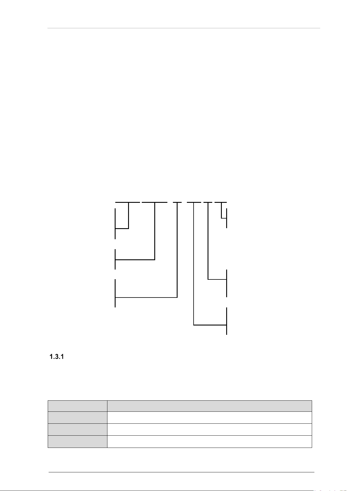
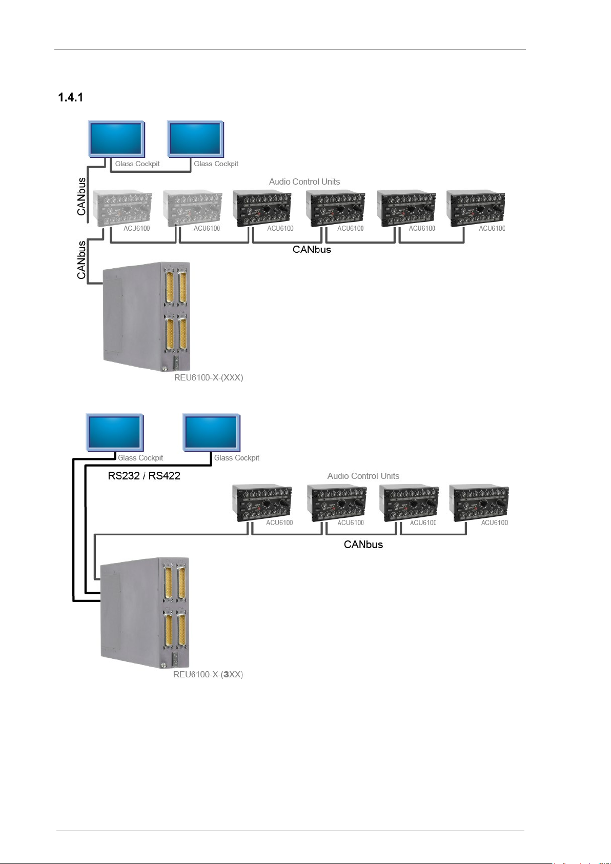
Examples of System Block Diagram
Figure 1: REU6100 with CANbus Interface (Glass Cockpit possible)
Figure 2: REU6100-X-(3XX) with CANbus and RS232 / RS422 Interface
16 REU6100 DV64460.03 Issue 11 January 2019
Page 17
Becker Avionics
General Description
Associated Devices
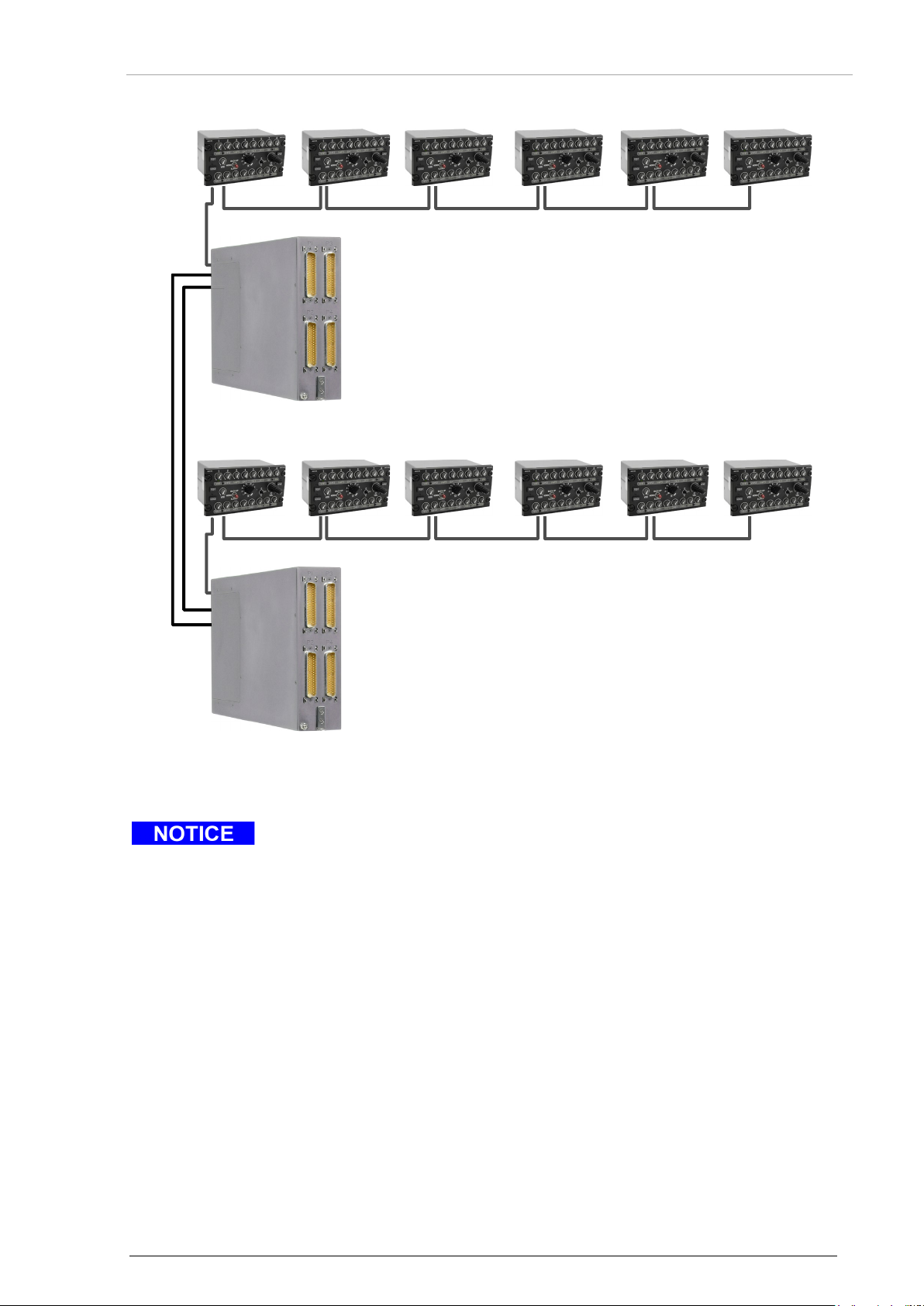
REU6100-X-(3XX).
ACU6100
ACU610
0
ACU6100 ACU6100 ACU6100 ACU6100
Audio Control Units
CANbus
CANbus
REU6100-X-(
3XX)
ACU
6100 AC
U610
0 ACU
6100
ACU610
0 ACU
610
0 ACU61
00
Audio Control Units
CANbus
CANbus
REU6100-X-(3XX)
RS232 / RS422
Figure 3: Multi-REU6100-X-(3XX) with CANbus and RS232 / RS422 Interface
• You can also use ACU6101 as control devices.
• The one-to-one replace of a device REU6100-X-(3XX) with a device not
REU6100-X-(3XX) and vice versa is not possible.
• The pin assignment of connector P5 is different with the variant
DV64460.03 Issue 11 January 2019 REU6100 17
Page 18

General Description
Becker Avionics
Scope of Functionality
1.5 Scope of Functionality
The REU6100 is for installation in the avionics compartment of an aircraft.
• It is a device in a standard ATR ¼ short case.
• The device connectors are on the front and back side of the REU6100.
o The connectors are coded to prevent misconnection.
• The REU6100 receives the commands from the audio control devices and accordingly
influences and processes all incoming and outgoing audio signals.
• The REU6100 supplies the logical functions necessary to operate the transceivers and for
aircraft intercommunication.
• The REU6100 supplies up to 10 different tone signals.
o The tone signals can be managed through discrete control lines.
• The audio processing circuits are in a modular design.
o Each external control device (e.g. ACU610X) is connected to an individual
processing module inside the REU6100.
o From electrical and mechanical points of view the modules are identical for easy
upgrade and interchange work.
Audio Channel In/Outputs
• The device has 22 balanced audio inputs, as follows:
o 8 transceivers or 7 transceivers and PA amplifier.
o 8 receivers.
o 6 fixed inputs.
• The input sensitivity for each transceiver and receiver is in the range of 2.5…20 V. The
input sensitivity is programmable with the configuration software.
• The input sensitivity for the fixed input 1…3 is in the range of 5…40 V. The input
sensitivity is programmable with the configuration software.
• The input sensitivity for the fixed input 4…6 is in the range of 2.5…20 V and under main-
volume control. The input sensitivity is programmable with the configuration software.
• Control of monitoring volume of the TX and RX channels connected in the range of
0...-48 dB.
• Main volume control by 0…-48 dB for headphone and, if enabled, for speaker amplifier.
• Supply of mike audio to 100…250 mV into 150 Ω (standard carbon mike) or 0.5…4 mV
into 20 Ω (dynamic mike):
o Automatic Gain Control (AGC).
o Providing the standard mike supply.
• Supply of a balanced audio output of 0.07…1.5 V into 150 Ω and distribution to 8 TX
modulation lines (configurable).
• Distribution of the PTT to 8 key lines. Keying logic to ensure transmission priority over
IC operation and to mute speaker outputs as well as non-desired RX and fixed inputs
during transmission.
• Supply of forced monitoring for all TX-channels with mike line selection.
• PTT priority for each operator (configurable high / low).
• PTT stuck detection.
• Generation of an artificial sidetone from the mike signal for radio transceivers which do not
feature a built-in sidetone during transmission (e.g. FM radios).
o Natural sidetone.
o Duplex sidetone.
o The sidetone can be individually programmed for every of the 8 transceivers by
configuration software from system integrator.
• Muting of receiver audio during transmission.
• Phone amplification of summed audio signal to 250 mW into 300 Ω or 500 mW into 8 Ω.
18 REU6100 DV64460.03 Issue 11 January 2019
Page 19

Becker Avionics
General Description
Intercom Function
• Supply of mike audio for intercom operation:
o Interconnection and separation of 3 IC circuits.
o Intercommunication VOX control.
o HOT MIKE activation.
o Addition of an incoming IC audio signal to the summed-up monitor audio;
adjustment of the IC audio via the ACU panel control by 0…-48 dB.
o Enhancing to IC-ring line level 0.775 V into 600 Ω.
o Extension of intercommunication by the IC-ring line audio in/out for external
devices like EB3100 (Ground Crew) or IC3100 (Intercom Amplifier).
o IC-ring line can be connected to the cockpit or cabin intercom circuit.
Signal Tones
• The REU6100 supplies up to 10 different tone signals in the frequency spectrum of
800…4800 Hz.
o 1x signal "Intercom request" (1600 Hz / 1200 Hz intermitted).
o 1x signal "E-call" (2400 Hz / 800 Hz / 1200 Hz intermitted).
o 8x alert signals (1x continuous, 3x pulsed, 4x intermittent) in the frequency
spectrum of 1200…4800 Hz.
• The signal tones are connected through 8 discrete control lines (active LO ≤ 1 V).
• It is possible to give different states to the signal tones:
o Muted during transmission.
o Set at the priority level (high, low, medium).
o Set at cancellation possibility.
Discrete In/Outputs
• 4 control outputs for specific logical external activations (all active low).
o DF-blanking (when a PTT is pushed).
o Cockpit call activation (if call is on).
o Cabin call activation (if cabin is isolated).
o Third intercom circuit status.
• 6 control inputs for specific logical DVCS-action (all active low).
o Winchman VOX-level selection.
o Winchman volume-level selection.
o Intercom request call input.
o E-call activation.
o Selective call activation.
o Warning tone cancellation.
Scope of Functionality
DV64460.03 Issue 11 January 2019 REU6100 19
Page 20

General Description
Becker Avionics
Scope of Functionality
Special Features
• The winchman connection facility in parallel to the related headset (ACU610X).
o Individual VOX level and volume level adjustment is possible through discrete
control lines.
• Turn on and off the speaker amplifiers and supply of an output of 12 W into 4 Ω.
• Muting of the cockpit speakers during transmission and intercom operation to avoid
acoustic feedback (configurable).
• By a "VOICE-filter", an incoming 1020 Hz tone can be attenuated at least 26 dB for
listening to the NAV voice modulation without disturbance. The filter function can be
connected to each of the eight receiver channels during factory or system integration
setup.
• Detection of a selective call signal by a discrete input from one of the 8 com radios
(configurable).
o Supply of a visual indication on the audio control device.
• Forced monitoring of the audio signal (configurable).
1.5.5.1 Built-in Tests
• The REU6100 device has different built-in tests.
• The tests monitor the system equipment and some internal circuits.
o PBIT: A system self-test starts after power-on.
o CBIT: A background test routine runs continuously during normal operation.
o IBIT: An additional test can be manually started.
1.5.5.2 Marker Mute Function
• If set by the operator the marker channel is muted for 30 seconds.
• The marker mute function can be individual enabled for each receiver channel and
operator in the configuration setup.
1.5.5.3 Emergency Operation (Back-Up Operation)
• Relay controlled fall back in case of emergency operation (back-up): Assignment of radios
and receivers to their operators.
o Headset 1 (normally the pilot) is connected to TX1 and FIX1,
o Headset 2 (copilot) to TX2 and FIX2.
• Back-up operation is started either manually through the hard-wired BACK-UP switches
on the ACU610Xs (if connected), or automatically upon power supply failure to the
REU6100, or if the internal power supply of the REU6100 itself is defective (this function
with pilot’s and copilot’s audio control devices only).
1.5.5.4 Slave Operation
• Relay controlled activation of slave operation to connect one operator headset in parallel
to others (this function with pilot’s and copilot’s audio control devices only).
20 REU6100 DV64460.03 Issue 11 January 2019
Page 21
Becker Avionics
General Description
Features for Special Mission Operation
• Dual transmit and multi transmit (simulcast):
Is for the selection of two predefined radios, or individual more than two radio for
simultaneous transmission.
• Guard radio:
Is for the selection of a radio by a separate PTT control (external discrete input). Two
radios can be configured for this function.
• Headset only operation:
Operator without a control device participate always intercommunication and can be
configured for monitoring TX/RX or FIX input-channels. By the discrete input lines an
IC-key and PTT-key can be connected. On one predefined TX-channel transmission is
possible. The connection to another operator with ACU is possible by the configuration
setup.
• Relay mode:
The REU6100 can operate in relay mode operation alternative to dual TX and multi
TX mode.
Communication Interfaces
• CANbus
o Control data interface between REU6100 and ACU610X.
• RS232/RS422
o Control data interface between REU6100-X-(3XX) and glass cockpit or between
two REU6100-X-(3XX) as multi-REU application.
Memory Device EM6100
EM6100 is a memory device.
• It is a small device connected to the REU6100 used to store all system configuration
parameters.
• It allows a quick field replacement of the REU6100 without reconfiguration of the replacing
REU6100 on the bench.
Scope of Functionality
Figure 4: External Memory Module - EM6100
DV64460.03 Issue 11 January 2019 REU6100 21
Page 22

General Description
Becker Avionics
The device(s) may be installed on an aircraft only by an approved aeronautical
Cleaning:
o These cleaning agents can cause damages.
Excessive pulses on the DC bus of the aircraft may cause damage on REU6100.
The product is to be used inside the declared limits.
Restriction for Use
1.6 Safety-Conscious Utilization
For safe operation of the product the notes have to be obeyed:
company (e.g. Part 145) which shall also examine and examine the installation.
• The installation of the device into an aircraft may be carried out only by
an authorized installation company. The country regulations always have
to be obeyed.
• Use the product only within the specified conditions, see "Technical
Data", page 23.
• Power supply:
o Do not connect the device to AC sources.
o Make sure that the device is connected to the mandatory DC source,
see "Technical Data", page 23.
o Do not connect the device with reversed polarity to the DC source.
• Circuit breaker:
o Use the recommended fuses in the power supply line for the
protection of the application, see "Technical Data", page 23.
• Do not use aggressive cleaning agents e.g. Acetone.
1.7 Restriction for Use
22 REU6100 DV64460.03 Issue 11 January 2019
Page 23
Becker Avionics
General Description
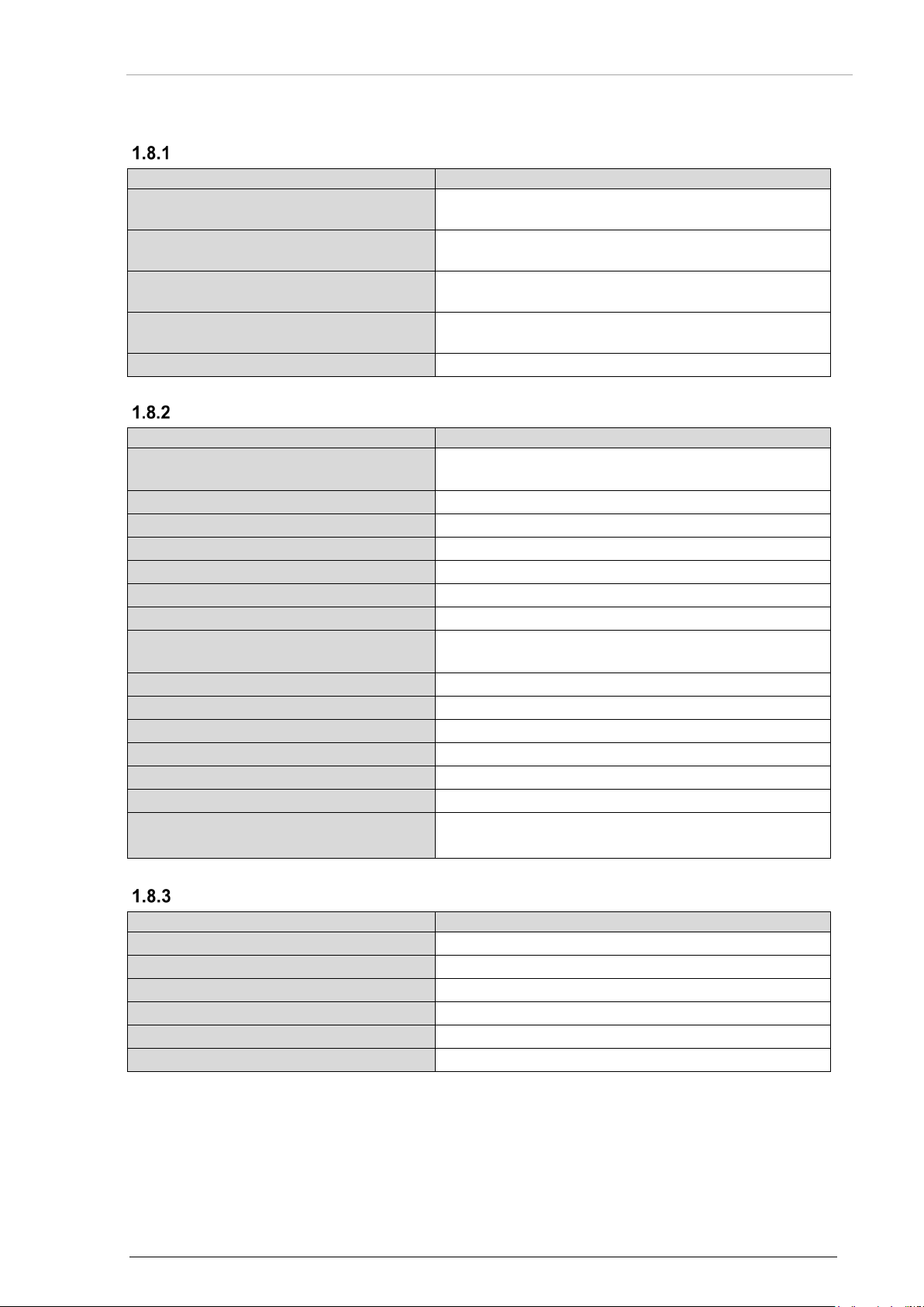
1.8 Technical Data
REU6100
Specifications (Power Supply)
Supply voltage (Bus) I
27.5 V DC nominal,
Supply voltage (Bus) II
27.5 V DC nominal,
Back-up voltage (Bus)
27.5 V DC nominal,
Current consumption (with 6 ACU’s)
4.5 A peak,
Recommended external fuse protection
5 A
REU6100
Specifications (Monitoring)
Transceiver Inputs
Number
8
Sensitivity
2.5…20 V adjustable
Impedance
600 Ω balanced / floating
Switch-off attenuation
≥ 80 dB
Crosstalk attenuation between inputs
≥ 70 dB
Individual volume control range
0…-48 dB
Forced monitoring
0…-48 dB
Navigation Receiver Inputs
Number
8
Sensitivity
2.5…20 V adjustable
Impedance
600 Ω balanced / floating
Switch-off attenuation
≥ 80 dB
Crosstalk attenuation between inputs
≥ 70 dB
Individual volume control range
0…-48 dB
Muting during transmission
≥ 80 dB
Identification filter attenuation (1020 Hz)
≥ 26 dB
REU6100
Specifications (Fixed Inputs)
Number
6
Sensitivity channel 1…3
5…40 V adjustable
Sensitivity channel 4…6
2.5…20 V adjustable (under control of main volume)
Impedance
600 Ω balanced / floating
Crosstalk attenuation between inputs
≥ 70 dB
Muting during transmission
≥ 80 dB
Power Supply
Monitoring
Technical Data
18.0 V DC emergency
18.0 V DC emergency
18.0 V DC emergency
1.5 A average
Fixed Inputs
DV64460.03 Issue 11 January 2019 REU6100 23
can be connected to any RX channel
Page 24

General Description
Becker Avionics
Technical Data
REU6100
Specifications (Tone Generator)
Continuous tone
2400 Hz
Pulsed tones
1600 Hz, 2400 Hz, 3840 Hz
Intermittent tones
1200 Hz, 2133 Hz, 3200 Hz, 4800 Hz
Service tone 1 (Intercom request)
1600 Hz / 1200 Hz intermittent
Service tone 2 (Emergency call)
2400 Hz / 800 Hz / 1200 Hz intermittent
Alert tones
Input No. Alert Tone
Pulsed means
TON = T
= 0.5 s
Intermitted means
3 pulses 0.17 s, repetition rate 2.5 s
Activation (alert tone control lines)
active LO, ≤ 1.5 V
Input current
≤ 1 mA
REU6100
Specifications (Speaker Amplifier)
Number
2
Output power
12 W (6.93 V) into 4 Ω (-0.5 / +1.0 dB) at normal supply
Overload protection
thermally output
Type
unbalanced
Distortion
≤ 2.5% @1 kHz
Frequency response
300 Hz…6 kHz (0/- 3 dB)
Switch-off attenuation
≥ 80 dB
Signal-to-noise ratio
≥ 70 dB
Main volume control range
0…-48 dB
Muting during transmission
≥ 80 dB
Muting during intercom operation
≥ 80 dB
REU6100
Specifications (Headphone Amplifier)
Number
4 or 6 (depends on variant)
Output power
250 mW (8.66 V) into 300 Ω or 500 mW (typical) into
Distortion
≤ 2.5% @1 kHz
Frequency response
300 Hz…6 kHz (0/- 3 dB)
Signal-to-noise ratio
≥ 70 dB
Main volume control range
0…-48 dB
Tone Generator
1 2400 Hz continuous
2 1600 Hz pulsed
3 2400 Hz pulsed
4 3840 Hz pulsed
5 1200 intermittent
6 2133 intermittent
7 3200 intermittent
8 4800 intermittent
OFF
Speaker Amplifier
Headphone Amplifier
voltage
24 REU6100 DV64460.03 Issue 11 January 2019
8 Ω or
2x 250 mW into 2x 8 Ω balanced transformer output,
ungrounded
Page 25

Becker Avionics
General Description
Mike Amplifier
REU6100
Specifications (Mike Amplifier)
Number
4 or 6 (depends on variant)
Mike Input (Standard Carbon Mike)
Sensitivity
100…250 mV nominal
Impedance
150 Ω
Excitation voltage (idle mode)
12 VDC
Feed resistance
390 Ω
Mike Input (Dynamic Mike)
Sensitivity
0.5…4 mV nominal
Impedance
20 Ω balanced / floating
Automatic Gain Control (AGC)
AGC threshold (adjustable)
80…150 mV (standard mike)
Output regulation (∆Ue = +20 dB)
≤ +2 dB
REU6100
Specifications (Transceiver Modulation)
Mike Line Amplifier
Number of mike lines
8
Output voltage
70 mV…1.5 V adjustable
Load impedance
150 Ω nominal distortion
Frequency response
300 Hz…6 kHz (0/-3 dB)
Signal-to-noise ratio
≥ 65 dB
Natural / Artificial and Duplex Sidetone
-individually selectable for each mike line-
Sidetone level
0…-15 dB selectable step 3 dB, standard - 6 dB
Key Lines (PTT Out)
Number
8
Switch action
active LO
Switch capability
27.5 VDC for OFF condition;
REU6100
Specifications (CRV Outputs)
Number
2
Channel 1 (pilot)
natural mike + headphone
Output voltage
Mike signal: 800 mV -1 dB / +3 dB headphone
Impedance
5 kΩ
Channel 2 (copilot)
natural mike + headphone
Output voltage
Mike signal: 800 mV -1 dB / +3 dB headphone
Impedance
5 kΩ
Transceiver Modulation
Technical Data
0.2…1 mV (dynamic mike)
Cockpit Voice Recorder (CVR)
≤ 2.5% @1 kHz
max. 500 mA in LO condition
signal: -3 dB referred to mike
signal: -3 dB referred to mike
DV64460.03 Issue 11 January 2019 REU6100 25
Page 26

General Description
Becker Avionics
Technical Data
REU6100
Specifications (Discrete In/Outputs)
Control Inputs (Discrete)
Number
6
Activation
active LO, ≤ 1.5 V
Input current
1 mA
Control Outputs (Discrete)
Number
4
Switch action
active LO
Switch capability
27.5 VDC for OFF condition;
Back-up Monitor
Number
1
Switch action
open contact
Norm Mode Output
27.5 VDC for OFF condition;
DC-Output
DC output
27.5 VDC / 500 mA
Control In/Outputs
Input No. Default Function
1 Winchman VOX-level selection
2 Intercom request activation (1600 Hz /
1200 Hz intermitted)
3 Winchman volume level selection
4 Alert tone cancellation
5 SELCALL / 3rd-IC-circuit activation
6 Emergency call activation (2400 Hz /
800 Hz / 1200 Hz intermitted
Output No. Default Function
1 DF- blanking
2 Cockpit CALL indication
3 Cabin CALL indication
4 3
rd
-IC-circuit activation (status indication)
max. 500 mA in LO condition
max. 500 mA in LO condition
26 REU6100 DV64460.03 Issue 11 January 2019
Page 27
Becker Avionics
General Description
REU6100
Specifications (Intercom Operation)
Number of participants
up to 6 clients directly connected plus clients connected
VOX threshold (adjustable)
10…100 mV (standard mike)
VOX hold time
0.5…3 s, adjustable
Distortion
≤ 2.5% @1 kHz
Frequency response
300 Hz…6 kHz (0/-3 dB)
Signal-to-noise ratio
≥ 60 dB
Input/output voltage on IC-ring audio lines
775 mV / 0 dBm
Input/output impedance of IC-ring audio
600 Ω (must be terminated)
Priority muting during transmission
≥ 80 dB
Intercom switch-off attenuation
≥ 80 dB
Intercom circuits
cockpit / cabin / 3rd-IC-circuit
Call activation or discrete input
CALL button (selectable)
Quit function connection/separation of
ISOL button (selectable)
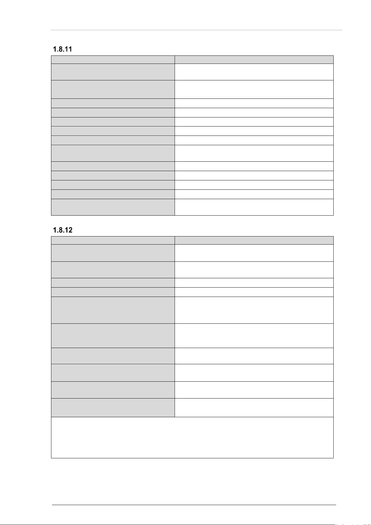
REU6100
Specifications (Build In Test Equipment (BITE)
Power On BuiId-In Test (PBIT)
Activation
Start automatically with power on
Test scope for REU, all ACUs and EM6100
Controllers and memories, tone generator, headphone
Indication system under test
Test LED lights up on ACU610X
Duration
max. 5 s
Test result output
GO: After test is finished, the test LED is off
Continuous Build-In Test (CBIT)
Activation
Permanently active coverage, controllers and data
Failure indication
Optical; TEST LED flashes and can be reset on
Initiated Build-In Test (IBIT)
Activation
Push the TEST button on ACU610X
Build-In Test Representation
Test running indicator
Test LED lights up
Test result output
GO: The test LED is off
test activations and indications.
Intercom Operation
lines
IC-circuits
Build In Test Equipment (BITE)
Technical Data
to IC line
50…500 µV (dynamic mike)
if connected
and speaker amps., power supply
(The system operates in normal mode after successful test)
NOGO: The test LED flashes
transfer
ACU610X, if no fatal error
NOGO: The test LED flashes
• A short push of the test button acknowledge the failure indication.
• The last 10 IBIT results are stored in a non-volatile memory and can be read out with the
configuration software.
• For REU6100-X-(3XX) variant with glass cockpit, please see related glass cockpit manual for
DV64460.03 Issue 11 January 2019 REU6100 27
Page 28
General Description
Becker Avionics
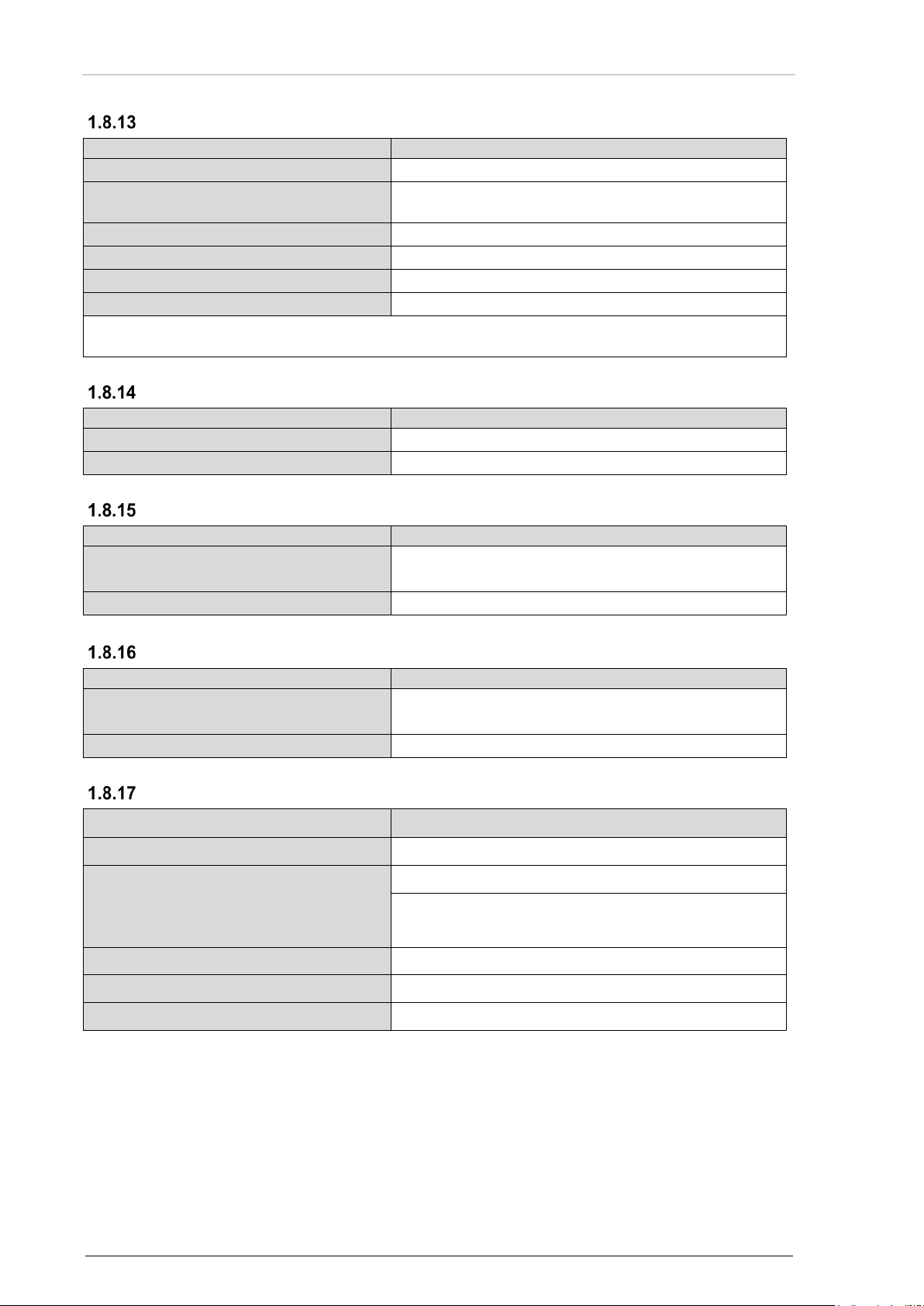
Technical Data
REU6100
Specifications (Back-up Operation)
Manual activation
Use the back-up switch at ACU1 or ACU2
Automatic activation
Upon supply busses failure or defection of internal
Transceiver (radio) assignment
ACU1 - TX1, ACU2- TX2
Fixed input
ACU1 - FIX1, ACU2- FIX2
Intercom level pilot/copilot
Fixed at 50%
CVR 1and 2 level
Fixed at 50%
For REU6100-X-(3XX) variant with glass cockpit, please see related glass cockpit manual for
REU6100
Specifications (Control Data Interface REU - ACU)
Interface
CANbus
Protocol
Becker specific (Becker Bus Protocol proprietary)
REU6100-X-(3XX)
Specifications (Control Data Interface REU - Glass )
Interface
RS232/422, baud rate 38400 b/s,
Protocol
Becker specific (Becker Bus Protocol proprietary)
REU6100-X-(3XX)
Specifications (Control Data Interface REU - REU )
Interface
RS232/422, baud rate 38400 b/s,
Protocol
Becker specific (Becker Bus Protocol proprietary)
REU6100
Specifications
Dimensions HxWxD
195 x 57 x 338.50 mm
Dimensions depth with EM6100
379.00 mm
Weight
REU6100
≤ 3 kg
Mounting tray MT519
< 0.5 kg
Case size
ATR fixture
Case material (REU6100)
AIMg
back-up activations and indications.
Back-up Operation
Control Data Interface REU - ACU
Control Data Interface REU - Glass Cockpit
power supply or processor failure
8 data, no parity, 1 stop bit
Control Data Interface REU - REU
8 data, no parity, 1 stop bit
Dimensions & Weight
28 REU6100 DV64460.03 Issue 11 January 2019
Page 29

Becker Avionics
General Description
Technical Data
REU6100
Specifications
D-Sub 50-pin male shift lock
4x with locking devices
19pol male
1x bayonet,
Sub miniature 5-pole female
1x for memory module EM6100
Device Connectors
The connectors are coded to prevent misconnection.
Souriau, Type 851-02 E14-19 P50, shell 14
Software
In accordance with EUROCAE / RTCA document ED-12B/DO-178B the software is specified as:
LEVEL C
1.8.19.1 Configuration Software
Detailed information please see "Configuration Software" page 69.
Hardware
Complex Electronic Hardware (CEH) is used inside REU6100-X-(XXX).
In accordance with system development assurance level of the DVCS6100 the Hardware Design
Assurance Level is:
LEVEL C
The DVCS6100 has been certified in year 2005 and has been qualified in accordance with all
standards which have been required by the authorities EASA and FAA at that time.
To apply RTCA DO-254 has not been required by the authorities and has therefore not been applied.
Continued Airworthiness
• Maintenance of the REU6100 is "on condition" only.
• Periodic maintenance of this product is not required.
DV64460.03 Issue 11 January 2019 REU6100 29
Page 30

General Description
Becker Avionics
Characteristics
Section
Cat.
Condition
Temperature and Altitude
4
D1
Ground Survival Low Temperature
4.5.1
D1
-55 °C
Short-Time Operating Low Temperature
4.5.1
D1
-40 °C
Operating Low Temperature
4.5.2
D1
-40 °C
Ground Survival High Temperature
4.5.3
D1
+85 °C
Short-Time Operating High Temperature
4.5.3
D1
+70 °C
Operating High Temperature
4.5.4
D1
+70 °C
In-Flight Loss of Cooling
4.5.5
X
no auxiliary cooling required
Altitude
4.6
D1
50 000 ft
Temperature Variation
5
B
5 °C per minute
Humidity
6
B
48 h at 65 °C at 95% relative humidity
Shock
7.2
B
6 g in all directions
Crash Safety
7.3
B
20 g shock; 20 g acceleration
Vibration
8
S; U
M; G
Explosion Proofness
9
X
-
Waterproofness
10
X
-
Fluids Susceptibilities
11
X
-
Sand and Dust
12
X
-
Fungus Resistance
13
X
-
Salt Spray
14
X
-
Magnetic Effect
15
Z
less than 0.3 m
Power Input
16
B
-
Voltage Spike
17
A
-
Audio Freq. Conducted Susceptibility
18
B
-
Induced Signal Susceptibility
19.0
AC
-
Radio Frequency Susceptibility
20
WR
-
Emission of Radio Frequency Energy
21
M
-
Lightning Induced Transients
22
A3E3X
Lightning Direct Effects
23
X
-
Icing
24
X
-
Electrostatic Discharge (ESD)
25
A
-
Fire, Flammability
26
X
-
Technical Data
Environmental Conditions
The test was done in accordance with EUROCAE/RTCA ED-14E/DO-160E under consideration of the
recorded environmental categories and conditions:
Susceptibility
30 REU6100 DV64460.03 Issue 11 January 2019
-
Page 31

Becker Avionics
General Description
Certifications
Specifications
ETSO
ETSO C50c
FAA
TSO-C139
REU6100-X-(XXX) meets the requirements of:
Technical Data
EASA.21O.443
DV64460.03 Issue 11 January 2019 REU6100 31
Page 32

General Description
Becker Avionics
Order Code
Qty
Device
1 REU6100-2-(010), max. 4 user
Article No. 0586.471-921
1
REU6100-2-(011), max. 4 user, XAC configuration data
Article No. 0606.944-921
1
REU6100-2-(110), max. 4 user, with EM6100
Article No. 0608.254-921
1
REU6100-3-(010), max. 6 user
Article No. 0588.946-921
1
REU6100-3-(110), max. 6 user, with EM6100
Article No. 0608.262-921
1
REU6100-3-(120), max. 6 user, with EM6100, extended short
Article No. 0643.505-921
1
REU6100-3-(310), max. 6 user, with EM6100, RS232/RS422
Article No. 0643.521-921
Qty
Mounting
1
MT519-1 Mounting
Article-No. 0890.790-261
Qty
External Memory
1
Article-No. 0608.270-921
Qty
Cables
1
1K6100 Service cable
Article-No. 0608.750-276
1
SCK6100-1 Service cable kit
Article-No. 0615.889-954
Qty
Connector
1
Service connector, 9-pol. D-Sub connector, crimp
Article-No. 0774.413-277
Qty
Connector Kit
1
CK5101-C (crimp version)
• 4x Resistor metal film 121 Ohm
Article-No. 0586.870-954
1
CK5103-C (crimp version) Manufacturer Commital
• 4x Resistor metal film 121 Ohm
Article-No. 0614.981-954
Qty
Configuration Software Set
1
CSW6100-2 configuration software set
1x CSW6100-2 manual (on CodeMeter© stick)
Article-No. 0608.602-919
1.9 Order Code
Remote Electronic Unit - REU6100
time temperature
Accessories
EM6100-(000) External Memory
• 1x 19-pol. cable connector, crimp
• 4x 50-pol. cable connector, crimp
• 4x Coding pins
• 4x Connector housing
• 1x 19-pol. cable connector, crimp
• 4x 50-pol. cable connector, crimp
• 4x Coding pins
• 4x Connector housing
• 1x CAN USB adapter
• 1x CodeMeter© stick
32 REU6100 DV64460.03 Issue 11 January 2019
•
Page 33

Becker Avionics
General Description
Documentation
Qty
Documentation
1
REU6100 Installation and Operation Manual, English
Article-No. 0589.829-071
1
REU6100 Maintenance and Repair Manual, English
Article-No. 0589.837-071
1
Serial Protocol RS232/RS422/CANbus - User Manual, English
Article-No. 0654.760-071
Order Code
DV64460.03 Issue 11 January 2019 REU6100 33
Page 34

General Description
Becker Avionics
Order Code
Blank Page
34 REU6100 DV64460.03 Issue 11 January 2019
Page 35

Becker Avionics
Installation
Order Code
2 Installation
The installation of the device(s) depends on the type of aircraft and its equipment and therefore only
general information can be given in this section.
Any deviations from the installation instructions prescribed in this document are under own
responsibility.
In this chapter you can read about:
2.1 Packaging, Transport, Storage ................................................................................................... 36
2.2 Device Assignment ..................................................................................................................... 37
Scope of Delivery .............................................................................................................. 37
State of Delivery ................................................................................................................ 37
Additional Required Equipment ........................................................................................ 37
Type Plate ......................................................................................................................... 38
Software/Firmware Status - Functionality ......................................................................... 38
2.3 Serial Interface Description ......................................................................................................... 38
2.4 Installation Requirements ............................................................................................................ 39
2.5 Dimensions.................................................................................................................................. 40
REU6100 .......................................................................................................................... 40
Mounting Tray MT519-1.................................................................................................... 41
REU6100 with Mounting MT519-1 and Connectors ......................................................... 42
2.6 Connector Pin Assignments ........................................................................................................ 43
Connector P1 .................................................................................................................... 44
Connector P2 .................................................................................................................... 45
Connector P3 .................................................................................................................... 46
Connector P4 .................................................................................................................... 48
Connector P5 - not for variant -(3XX) ............................................................................... 49
Connector P5 - REU6100-X-(3XX) ................................................................................... 50
Connector J6 ..................................................................................................................... 50
Address Coding ................................................................................................................ 51
2.7 Aircraft Wiring .............................................................................................................................. 51
Electrical Bonding and Grounding .................................................................................... 51
REU6100-X-(3XX) - RS422 / RS232 / CAN Connections ................................................. 52
REU6100 - Power Supply Connections ............................................................................ 52
REU6100 - Headset Audio and PTT Connections ........................................................... 53
REU6100 - Transceiver Connections ............................................................................... 54
REU6100 - Receiver and CVR Connections .................................................................... 55
REU6100 - FIX Audio, Alert Tones and IC Ring Connections ......................................... 56
REU6100 - Speaker, Back-up Act., Control and other Connections ................................ 57
CANbus Connector ........................................................................................................... 58
Wiring - REU6100 & ACU610X ........................................................................................ 59
Wiring - REU6100 & ACU610X with Service Connector (Option) .................................... 61
Wiring - REU6100 & ACU6100 (Fixed-Wing Version) with Service Connector (Option) . 63
Wiring - REU6100-X-(3XX) & ACU610X .......................................................................... 65
Wiring - REU6100-X-(3XX) & ACU610X & Glass Cockpit with Service Connector ......... 67
2.8 Configuration ............................................................................................................................... 69
Configuration Software (CSW6100) ................................................................................. 69
EM6100 ............................................................................................................................. 69
2.9 Communication Interfaces .......................................................................................................... 69
CANbus Protocol for REU6100 ........................................................................................ 69
RS232/RS422 Protocol for REU6100 ............................................................................... 69
2.10 REU6100 Functions .................................................................................................................... 70
Headset ............................................................................................................................. 70
PTT Key ............................................................................................................................ 70
Output Level TX-Devices .................................................................................................. 70
Input Level TX-Devices ..................................................................................................... 70
Input Level RX-Devices .................................................................................................... 70
Sidetone ............................................................................................................................ 70
Forced Monitoring ............................................................................................................. 70
Audio Muting ..................................................................................................................... 70
FIX Input Channels (Warning Audio Tones) ..................................................................... 71
Speaker ............................................................................................................................. 71
Cockpit Voice Recorder (CVR) ......................................................................................... 71
DV64460.03 Issue 11 January 2019 REU6100 35
Page 36

Installation
Becker Avionics
The packaging material is inflammable, if it is disposed of improperly by burning,
Packaging, Transport, Storage
Alert Tones ........................................................................................................................ 71
Signal Tones ..................................................................................................................... 72
Activation Signal Tones ..................................................................................................... 72
Activation - Selective Call .................................................................................................. 72
Winchman Operation ........................................................................................................ 72
Intercom Circuits ............................................................................................................... 73
IC-Indications - Cockpit Call, Cabin Call, 3
rd
-IC-Circuit ..................................................... 73
Muting Signal..................................................................................................................... 75
Marker Mute Function ....................................................................................................... 75
Back-up Mode and Slave Mode ........................................................................................ 75
2.11 Special Functions ........................................................................................................................ 76
Double Transmit and Multi Transmit (Simulcast) Mode .................................................... 76
Guard Radio PTT Function ............................................................................................... 76
Relay Mode ....................................................................................................................... 77
Operation "Headset without ACU610X" ............................................................................ 78
Operation "Headset connected to ACU" ........................................................................... 78
Operation "3rd-IC-circuit" .................................................................................................. 78
Alternative Use of Alert Tones Activation Inputs ............................................................... 79
Data Interchange in Multi-REU Applications (RS232/RS422) .......................................... 81
2.12 Service Connector ....................................................................................................................... 82
Service Connector inside the Aircraft ................................................................................ 82
Service Cable Kit ............................................................................................................... 82
2.13 Block Diagram - DVCS6100 with Ground Crew .......................................................................... 83
2.14 Block Diagram - DVCS6100 with Intercom Amplifier .................................................................. 85
2.15 Block Diagram - DVCS6100 with Glass Cockpit Application ...................................................... 87
2.16 Block Diagram - DVCS6100 with Electronic Display Application ................................................ 89
2.17 Block Diagrams - DVCS6100 with Multi-REU Application .......................................................... 91
Block Diagrams - DVCS6100 with Multi-REU Application ................................................ 91
Block Diagram - DVCS6100 with Multi-REU & Glass Cockpit Application ....................... 92
2.18 Warning and Failure Indications .................................................................................................. 92
2.19 Post Installation Check ................................................................................................................ 93
Mechanical Installation and Wiring Check ........................................................................ 93
Power Supply .................................................................................................................... 93
Power On Check ............................................................................................................... 93
2.1 Packaging, Transport, Storage
Visually inspect the package contents for signs of transport damage.
toxic fumes may develop.
Keep the packaging material and use it in the case of a return shipment. Improper or faulty packaging
may lead to transport damages.
Make sure to transport the device always in a safe manner and with the aid of suitable lifting
equipment if necessary. Do never use the electric connections for lifting. Before the transport, a clean,
level surface should be prepared to put the device on. The electric connections may not be damaged
when placing the device.
First Device Checkup
• Check the device for signs of transport damages.
• Please make sure that the indications on the type plate correspond to your purchase
order.
• Make sure that the equipment is complete ("Scope of Delivery", page 37).
Storage
If you do not wish to mount and install the device immediately, make sure to store it in a dry and clean
environment. Make sure that the device is not stored near strong heat sources and that no metal
chippings can get into the device.
36 REU6100 DV64460.03 Issue 11 January 2019
Page 37

Becker Avionics
Installation
2.2 Device Assignment
This manual is valid for the following devices:
• REU6100-2-(XXX) + accessories
• REU6100-3-(XXX) + accessories
Scope of Delivery
• Manuals.
o Installation and Operation manual.
• The device(s) in accordance with your order.
• Documents of Certifications.
o Authorized Release Certificate (EASA Form 1).
State of Delivery
• The device(s) are ready for use with factory default adjustments.
• The REU6100-2-(011) variant has a special configuration.
Additional Required Equipment
• EM6100 External Memory module (depends on variant).
• Mounting MT519-1.
• Connectors + cables.
• Audio control device(s).
• Headset.
Details see "Accessories", page 32.
Device Assignment
DV64460.03 Issue 11 January 2019 REU6100 37
Page 38

Installation
Becker Avionics
PN:
Type designation:
SN:
Unique number of the particular device
AN:
Article number
DoM:
Date of Manufacturing
Software:
Compliance and Certifications:
Serial Interface Description
Type Plate
The device type is specified by the type plate (on the housing):
Example:
Figure 5: Type Plate (Example)
Explanation:
REU = Remote Electronic Unit
6100 = Model number (family)
Options:
-2-: 4 headset connections (max. 4 audio control devices)
-3-: 6 headset connections (max. 6 audio control devices)
(0XX): Standard, no memory module EM6100
(1XX): With memory module EM6100
(3XX): RS422 interface + memory module EM6100
(X1X): Standard
(X2X): Extended Short Time Temperature 85 °C
(X6X): Intercom Amplifier only
(XX0): Standard Configuration Data
(XX1): Customized Configuration Data
Corresponding to the shown version
Corresponding to the shown text and logos
Software/Firmware Status - Functionality
The implemented firmware version can be checked with the configuration software CSW6100.
Please contact our Customer Service Department for detailed information about software modification.
2.3 Serial Interface Description
For the adaption of a glass cockpit device or a multi-REU installation a detailed description for the
serial data communication is published by the manual: "Serial Protocol RS232/RS422/CANbus". The
manual is available on special request and necessary agreements.
38 REU6100 DV64460.03 Issue 11 January 2019
Page 39

Becker Avionics
Installation
Installation Requirements
The installation of REU6100 into an aircraft may be carried out by an authorized
• Forced cooling is not required.
REU6100 is made for installation in cockpit environment of fixed and rotary
operate this equipment.
2.4 Installation Requirements
The installation of the device(s) depends on the type of aircraft and its equipment and therefore only
general information can be given in this section.
installation company. The country regulations always have to be obeyed.
• The device must not be opened.
• Keep an efficient distance of the devices with integrated ventilator fans in
order to ensure free circulation of the cooling air.
• The installation area must have a minimum distance of 30 cm from the
magnetic aircraft compass, to prevent any interference to the magnetic
compass.
wing aircraft.
These limitations apply for the installation:
• Installations must be in accordance with appropriate EASA or FAA
approved guidelines.
• The personnel installing this device must ensure that the aircraft
installation conditions are within the ETSO/TSO standards applicable
for the specific type or class of aircraft.
• The conditions and tests for ETSO/TSO approval of this article are
minimum performance standards.
• The equipment is not qualified for installation in areas with fluid
contamination.
• Changes or modifications made to this equipment not expressly
approved in written form by Becker may void the authorization to
DV64460.03 Issue 11 January 2019 REU6100 39
Page 40

Installation
Becker Avionics
Dimensions
"Center of Gravity" for REU6100 with EM6100.
Allowable deviation for dimensions without tolerances: DIN ISO 2768 T1 C (dimensions in mm)
xx...6 (±0.3)
>30...120 (±0.8)
>400...1000 (±2.0)
>6...30 (±0.5)
>120...400 (±1.2)
>1000...2000 (±3.0)
CENTER OF GRAVITY
25
(1.0)
57 (2.2)27.3
(1.1)
320 (12.6)
166.5 (6.6)
9 (0.4)
45.4 (1.8)
110 (4.3)
77.7 (3.1)
100 (3.9)
195 (7.7)
2.5 Dimensions
REU6100
Dimensions mm (inch)
Figure 6: Dimensions REU6100
Tolerances: ± 5 mm.
40 REU6100 DV64460.03 Issue 11 January 2019
Page 41

Becker Avionics
Installation
Mounting Tray MT519-1
Allowable deviation for dimensions without tolerances: DIN ISO 2768 T1 C (dimensions in mm)
xx...6 (±0.3)
>30...120 (±0.8)
>400...1000 (±2.0)
>6...30 (±0.5)
>120...400 (±1.2)
>1000...2000 (±3.0)
33.2
(1.3)
61 (2.4)
102 (4.0)
45
(1.8)
16 (0.6)
68 (2.7)
125 (4.9)
69 (2.7)
147.1 (5.8)
132.1 (5.2)
64 (2.5)
379 (14.9)
113.7 (4.5)
23.7 (0.9)
Ø5.2 (0.2)
Dimensions
Dimensions mm (inch)
Figure 7: Dimensions Mounting Tray MT519-1
DV64460.03 Issue 11 January 2019 REU6100 41
Page 42

Installation
Becker Avionics
Allowable deviation for dimensions without tolerances: DIN ISO 2768 T1 C (dimensions in mm)
xx...6 (±0.3)
>30...120 (±0.8)
>400...1000 (±2.0)
>6...30 (±0.5)
>120...400 (±1.2)
>1000...2000 (±3.0)
430 (16.9)
438.6 (17.3)
16.35
(0.6)
53.4 (2.1)48.85 (1.9)
19.6 (0.8)
Dimensions
REU6100 with Mounting MT519-1 and Connectors
Dimensions mm (inch)
Figure 8: Dimensions REU6100 with Mounting MT519-1 and Connectors
42 REU6100 DV64460.03 Issue 11 January 2019
Page 43

Becker Avionics
Installation
The connectors are coded to prevent misconnection.
P5
P1 P3
P4P2
J6
Power
Fix audio6
Fix audio5
Fix audio4
Fix audio3
Fix audio2
Fix audio1
Operator 1
(PTT, Slaved, Back-up)
Coding Pin
TX1 PTT out
RX8 audio
RX7 audio
RX6 audio
TX8 audio
TX7 audio
Power
Speakers
Control in
Control out
TX2...8 PTT out
Coding Pin
Operator 3, 4, 5, 6
(PTT)
Operator 2
(PTT, Slaved, Back-up)
Alert tone activation
RX5 audio
RX3 audio
RX1 audio
TX6 audio
TX4 audio
TX2 audio
DC Back-up GND
DC Back-up
Coding Pin
Headset Operator 6
Headset Operator 4
Headset Operator 2
Intercom
BUMonitor Out
RX4 audio
RX2 audio
TX5 audio
TX3 audio
TX1 audio
CVR1 Audio
CVR1/2 Common
Coding Pin
Headset Operator 5
Headset Operator 3
Headset Operator 1
Cockpit Voice Rec.
P4P2
P3P1
M
BA
L
K
J
H G F
T S E
U V R D
N P C
GND
BB1
BB2
B-Bus
Dev.Nr
Reset in
Reset out
P5
M
BA
L
K
J
H G F
T S E
U V R D
N P C
GND
BB1
BB2
B-Bus
0RX/TX
1RX
1TX
Reset inReset out
P5
Connector Pin Assignments
2.6 Connector Pin Assignments
DV64460.03 Issue 11 January 2019 REU6100 43
P5 for:
REU6100-X-(XXX)
not for variant -(3XX)
Figure 9: REU6100: Connector Pin Assignment - Overview
P5 for:
REU6100-X-(3XX)
Page 44

Installation
Becker Avionics
Connector Pin Assignments
P1/Pin
Signal name / Function
Remarks
17
HS 1 Mic in HI
Operator 1
16
HS 1 Mic in LO
Operator 1
33
HS 1 Mic in SH
Operator 1
49
HS 1 Phone out HI
Operator 1
48
HS 1 Phone out LO
Operator 1
32
HS 1 Phone out SH
Operator 1
15
HS 3 Mic in HI
Operator 3
14
HS 3 Mic in LO
Operator 3
31
HS 3 Mic in SH
Operator 3
47
HS 3 Phone out HI
Operator 3
46
HS 3 Phone out LO
Operator 3
30
HS 3 Phone out SH
Operator 3
13
HS 5 Mic in HI
Operator 5
12
HS 5 Mic in LO
Operator 5
29
HS 5 Mic in SH
Operator 5
45
HS 5 Phone out HI
Operator 5
44
HS 5 Phone out LO
Operator 5
28
HS 5 Phone out SH
Operator 5
11
CVR1- Audio out HI
Operator 1 (Pilot)
18
CVR2- Audio out HI
Operator 2 (Copilot)
10
CVR1/2 Common LO
CVR Signal ground
50
CVR Audio out SH
Shield
9
TX 1 Mic audio out HI
8
TX 1 Mic audio out LO
25
TX 1 Mic audio out SH
43
TX 1 Audio in HI
42
TX 1 Audio in LO
26
TX 1 Audio in SH
7 TX 3 Mic audio out HI
6 TX 3 Mic audio out LO
23
TX 3 Mic audio out SH
41
TX 3 Audio in HI
40
TX 3 Audio in LO
24
TX 3 Audio in SH
39
TX 5 Mic audio out HI
38
TX 5 Mic audio out LO
22
TX 5 Mic audio out SH
5
TX 5 Audio in HI
4
TX 5 Audio in LO
21
TX 5 Audio in SH
Connector P1
44 REU6100 DV64460.03 Issue 11 January 2019
Page 45

Becker Avionics
Installation
Connector P2
P2/Pin
Remarks
15
Alert Tone 1
Guard radio PTT activation / or a relay mode / or
16
Alert Tone 2
3rd Circuit isolation activation / or a relay mode /
17
Alert Tone 3
IC-PTT/HS1, TX-PTT/HS6 activation / or a relay
31
Alert Tone 4
IC-PTT/HS2, TX-PTT/HS5 activation / or a relay
32
Alert Tone 5
IC-PTT/HS3, TX-PTT/HS4 activation / or a relay
33
Alert Tone 6
IC-PTT/HS4, TX-PTT/HS3 activation / or a relay
47
Alert Tone 7
IC-PTT/HS5, TX-PTT/HS2 activation / or a relay
48
Alert Tone 8
IC-PTT/HS6, TX-PTT/HS1 activation / or a relay
49
Alert Tone GND
50
Alert Tone GND
29
Operator 2 PTT in
only for back-up mode
30
Operator 2 Slaved in
46
Operator 2 Back-up in
5
Control in 1
Winchman VOX level selection
6
Control in 2
Intercom request call input
22
Control in 3
Winchman volume level selection
11
Control in 4
Alert tone cancellation
12
Control in 5
Selective call / Guard radio PTT activation /
28
Control in 6
E-Call activation
25
TX 2 PTT out
26
TX 3 PTT out
27
TX 4 PTT out
41
TX 5 PTT out
42
TX 6 PTT out
43
TX 7 PTT out
44
TX 8 PTT out
40
TX2...8 Out GND
7
Control Out 1
DF blanking, "active LO" when any PTT is
23
Control Out 2
Cockpit CALL indication: "active LO" if CALL is
24
Control Out 3
Cabin CALL indication: "active LO" if cabin is
45
Control Out 4
"active LO" when 3rd-IC-circuit is isolated
Connector Pin Assignments
external TX indication
or external TX indication
mode / or external TX indication
mode / or external TX indication
mode / or external TX indication
mode / or external TX indication
mode / or external TX indication
mode / or external TX indication
3rd-IC-circuit activation
pushed
on
isolated,
flashing if CALL is on,
off if Cabin is connected
DV64460.03 Issue 11 January 2019 REU6100 45
Page 46

Installation
Becker Avionics
Connector Pin Assignments
P2/Pin
Remarks
38,21
Speaker 1 out (HI)
37,20
Speaker 1 out (LO)
39
Speaker 1 SH
3,2
Speaker 2 out (HI)
36,19
Speaker 2 out (LO)
4
Speaker 2 SH
35
DC1
34
GND1
1
DC2
18
GND2
13,14
GND
8, 9
GND
10
Coding Pin
P3/Pin
Signal name / Function
Remarks
1
HS 2 Mic in HI
Operator 2
2
HS 2 Mic in LO
Operator 2
18
HS 2 Mic in SH
Operator 2
35
HS 2 Phone out HI
Operator 2
36
HS 2 Phone out LO
Operator 2
19
HS 2 Phone out SH
Operator 2
3
HS 4 Mic in HI
Operator 4
4
HS 4 Mic in LO
Operator 4
20
HS 4 Mic in SH
Operator 4
37
HS 4 Phone out HI
Operator 4
38
HS 4 Phone out LO
Operator 4
21
HS 4 Phone out SH
Operator 4
5
HS 6 Mic in HI
Operator 6
6
HS 6 Mic in LO
Operator 6
22
HS 6 Mic in SH
Operator 6
39
HS 6 Phone out HI
Operator 6
40
HS 6 Phone out LO
Operator 6
23
HS 6 Phone out SH
Operator 6
41
TX 2 Mic audio out HI
42
TX 2 Mic audio out LO
25
TX 2 Mic audio out SH
9
TX 2 Audio in HI
10
TX 2 Audio in LO
26
TX 2 Audio in SH
43
TX 4 Mic audio out HI
Details about alert tones 1...8 see "Alert Tones" page 71.
Connector P3
46 REU6100 DV64460.03 Issue 11 January 2019
Page 47

Becker Avionics
Installation
Connector Pin Assignments
P3/Pin
Signal name / Function
Remarks
44
TX 4 Mic audio out LO
27
TX 4 Mic audio out SH
11
TX 4 Audio in HI
12
TX 4 Audio in LO
28
TX 4 Audio in SH
45
TX 6 Mic audio out HI
46
TX 6 Mic audio out LO
29
TX 6 Mic audio out SH
13
TX 6 Audio in HI
14
TX 6 Audio in LO
30
TX 6 Audio in SH
47
RX 1 Audio in HI
48
RX 1 Audio in LO
31
RX 1 Audio in SH
15
RX 3 Audio in HI
16
RX 3 Audio in LO
32
RX 3 Audio in SH
49
RX 5 Audio in HI
50
RX 5 Audio in LO
33
RX 5 Audio in SH
8
DC Bu +27.5 V
24
DC Bu GND
17
DC Out +27.5 V
34
DC Out +27.5 V
7
Coding Pin
DV64460.03 Issue 11 January 2019 REU6100 47
Page 48

Installation
Becker Avionics
Connector Pin Assignments
P4/Pin
Signal name / Function
Remarks
1
TX 7 Mic audio out HI
2 TX 7 Mic audio out LO
18
TX 7 Mic audio out SH
35
TX 7 Audio in HI
36
TX 7 Audio in LO
19
TX 7 Audio in SH
3
TX 8 / PA Mic audio out HI
4
TX 8 / PA Mic audio out LO
20
TX 8 Mic audio out SH
37
TX 8 Audio / PA Sidetone in HI
38
TX 8 Audio / PA Sidetone in LO
21
TX 8 Audio in SH
5 RX 6 Audio in HI
6 RX 6 Audio in LO
22
RX 6 Audio in SH
39
RX 7 Audio in HI
40
RX 7 Audio in LO
23
RX 7 Audio in SH
7
RX 8 Audio in HI
8
RX 8 Audio in LO
24
RX 8 Audio in SH
41
TX 1 PTT out
25
TX1 PTT GND
42
Operator 1 PTT in
only for back-up mode
26
Operator 1 Slaved in
10
Operator 1 Back-up in
43
FIX1 Audio in HI
44
FIX1 Audio in LO
27
FIX1 Audio in SH
11
FIX2 Audio in HI
12
FIX2 Audio in LO
28
FIX2 Audio in SH
45
FIX3 Audio in HI
46
FIX3 Audio in LO
29
FIX3 Audio in SH
13
FIX4 Audio in HI
14
FIX4 Audio in LO
30
FIX4 Audio in SH
Connector P4
48 REU6100 DV64460.03 Issue 11 January 2019
Page 49

Becker Avionics
Installation
P4/Pin
Signal name / Function
Remarks
47
FIX5 Audio in HI
48
FIX5 Audio in LO
31
FIX5 Audio in SH
15
FIX6 Audio in HI
16
FIX6 Audio in LO
32
FIX6 Audio in SH
49
DC1
50
GND1
17
DC2
33
GND2
34
GND
9
Coding Pin
P5/Pin
Signal name / Function
Remarks
L
Dev Address Bit 0
M
Dev Address Bit 1
A
Dev Address Bit 2
B Dev Address Bit 3
N Address GND
U
Reset out
V
Reset in
C BB1-HI-in
D BB1-LOW-in
P
BB1-SH-in
E
BB1-HI-out
F BB1-LO-out
R BB1-SH-out
G
BB2-HI-in
H
BB2-LO-in
S BB2-SH-in
J BB2-HI-out
K
BB2-LO-out
T
BB2-SH-out
Connector P5 - not for variant -(3XX)
Connector Pin Assignments
DV64460.03 Issue 11 January 2019 REU6100 49
Page 50

Installation
Becker Avionics
Connector Pin Assignments
P5/Pin
Signal name / Function
Remarks
L
0TX+
RS422
M
0TX- / 0TX
RS422 / RS232
A
0RX+ / 0RX
RS422 / RS232
B
0RX-
RS422
N
CH0 Shield
U Reset out
V
Reset in
C
1RX-
RS422
D
1RX+ / 1RX
RS422 / RS232
G
1TX- / 1TX
RS422 / RS232
H
1TX+
RS422
P
CH1 Shield
S Serial IF Ground
E BB1-HI-out
CAN1
F
BB1-LO-out
CAN1
R
BB1-SH-out
CAN1
J
BB2-HI-out
CAN2
K
BB2-LO-out
CAN2
T
BB2-SH-out
CAN2
J6/Pin
Signal name / Function
Remarks
1
VCC
Power supply
2
I2C CLK
Clock
3
Not connected
Reserved
4
I2C DAT
Data
5
GND
Power supply return
Connector P5 - REU6100-X-(3XX)
Connector J6
50 REU6100 DV64460.03 Issue 11 January 2019
Page 51

Becker Avionics
Installation
Aircraft Wiring
Address
Device
Bit 0 (Pin L)
Bit 1 (Pin M)
Bit 3 (Pin A)
Bit 3 (Pin B)
0000
ACU1
GND
GND
GND
GND
0001
ACU2
open
GND
GND
GND
0010
ACU3
GND
open
GND
GND
0011
ACU4
open
open
GND
GND
0100
ACU5
GND
GND
open
GND
0101
ACU6
open
GND
open
GND
The Installation of the device(s) depends on the type of aircraft and its equipment.
REU6100-X-(3XX).
Address Coding
• Set the address coding for the devices (REU6100 but not for variant REU6100-X-(3XX) by
connecting the pins L, M, A, B (ground or left open).
• This function is not used for REU6100 but necessary for ACU installation.
Therfore the ACU address coding is shown here in addition:
• Set the address coding for the devices (ACU) in the cable-plug connector to the ACU.
• Each ACU must have a different address:
2.7 Aircraft Wiring
Electrical Bonding and Grounding
The REU6100 has a threaded grounding bolt at the housing. Use this point as grounding contact.
It is therefore only possible to give general guidelines in this section.
• Use only cable fit for aviation (self-extinguishing).
• AW G 20 for power supply and AWG 24 for other cables.
• The interface lines are each to be laid as 2-core twisted and shielded
(AWG 24) cables.
• Each single cable harness of a device connector must have separate
shielding.
• Rubber sleeves are to be fitted over the soldering points on the device
connector.
• A fuse or circuit breaker should be fitted in the power supply of the
REU6100 (see "Technical Data" page 23).
• RF cable should not be included in the cable harnesses.
• Examine the wiring carefully before turn on the devices, make sure that
(UB+) and (GND) are not mixed up.
• The one-to-one replace of a device REU6100-X-(3XX) with a device not
REU6100-X-(3XX) and vice versa is not possible.
• The pin assignment of connector P5 is different with the variant
• Make sure that the device is correctly connected to aircraft ground
(structure).
• Make sure that the resistance between the component which ensure
equipment bonding and any point of this item of equipment do not exceed
2.5 mΩ.
DV64460.03 Issue 11 January 2019 REU6100 51
Page 52

Installation
Becker Avionics
REU6100-X-(3XX)
ACU
Glass cockpit
Glass cockpit
Reset out
Reset in
CAN1 in/out Shield
CAN1 in/out (LO)
CAN1 in/out (HI)
CH1 GND
1RX-
1RX+ / 1RX
1TX- / 1TX
1TX+
0TX+
0TX- / 0TX
0RX+ / 0RX
0RX-
CH0 GND
Serial IF GND
CAN2 in/out Shield
CAN2 in/out (LO)
CAN2 in/out (HI)
P
C
D
R
F
E
U
V
G
H
S
T
K
J
L
M
A
B
N
L
M
A
B
N
V
C
P
G
D
H
S
P
C
D
G
H
P5 P5
RS232RS422
121 Ω121 Ω
35
34
1
18
49
50
17
33
8
24
17
34
P2
P2
P4
P4
P3
P3
REU6100
DC 2 +27.5 V
DC 2 GND
DC out +27.5 V
DC out +27.5 V
DC Bu +27.5 V
DC Bu GND
DC 1 +27.5 V
DC 1 GND
DC 2 +27.5 V
DC 2 GND
DC 1 +27.5 V
DC 1 GND
Aircraft Wiring
REU6100-X-(3XX) - RS422 / RS232 / CAN Connections
Note: The pin assignment of connector P5 is different with the variant REU6100-X-(3XX).
For other REU variants please see "Connector P5 - not for variant -(3XX)" page 49.
REU6100 - Power Supply Connections
Figure 10: Wiring REU6100-X-(3XX) - RS422 / RS232 / CAN
Figure 11: Wiring - Power Supply
52 REU6100 DV64460.03 Issue 11 January 2019
Page 53

Becker Avionics
Installation
Headset 1 Audio out (HI
(LO
Shield
Mic Audio in (HI)
(LO
Headset 2 Audio out (HI
(LO
Shield
Mic Audio in (HI)
(LO
Headset 3 Audio out (HI)
(LO
Shield
Mic Audio in (HI)
(LO
Headset 4 Audio out (HI)
(LO
Shield
Mic Audio in (HI)
(LO
Headset 5 Audio out (HI)
(LO
Shield
Mic Audio in (HI)
(LO
Headset 6 Audio out (HI)
(LO
Shield
Mic Audio in (HI)
(LO
TX1 PTT out
TX1 PTT out GND
TX2 PTT out
TX3 PTT out
TX4 PTT out
TX5 PTT out
TX6 PTT out
TX8/PA PTT out
TX2...8 PTT out GND
TX7 PTT out
)
)
)
)
)
)
)
)
)
)
)
)
)
)
REU6100
P3
P1
P3
P1
P3
P4
P2
P1
49
48
32
33
17
16
35
36
18
19
1
2
47
46
30
31
15
14
37
38
20
21
3
4
45
44
28
29
13
12
39
40
22
23
5
6
41
25
25
26
27
41
42
43
44
40
DV64460.03 Issue 11 January 2019 REU6100 53
REU6100 - Headset Audio and PTT Connections
Figure 12: Wiring - Headset Audio and PTT
Aircraft Wiring
Page 54

Installation
Becker Avionics
Aircraft Wiring
9
8
TX1 Mic Audio out (
HI
)
25
26
43
42
(LO
)
Shield
TX
1 Audio in
(HI
)
(LO
)
41
42
TX
2 Mic Audio out
(
HI)
25
26
9
10
(LO
)
Shield
TX
2 Audio in
(HI
)
(LO)
7
6
TX3
Mic Audio out (
HI
)
23
24
41
40
(LO)
Shield
TX
3 Audio in
(HI
)
(LO
)
43
44
TX4
Mic Audio out
(HI
)
27
28
11
12
(LO)
Shield
TX
4
Audio in
(HI
)
(LO)
39
38
TX5 Mic Audio out
(HI)
21
22
5
4
(LO
)
Shield
TX5 Audio in (HI)
(
LO)
45
46
TX6 Mic Audio out
(HI
)
29
30
13
14
(LO
)
Shield
TX6
Audio in (HI
)
(LO)
1
2
TX
7 Mic Audio out (HI)
18
19
35
36
(LO)
Shield
TX7 Audio in (HI
)
(LO)
3
4
TX8/PA Mic Audio out (HI)
20
21
37
38
(
LO)
Shield
TX
8/PA Audio in (HI
)
(LO)
Transceiver
Transceiver
Transceiver
Transceiver
Transceiver
Transceiver
Transceiver
Transceiver
P1
P
3
P
1
P3
P
1
P3
P4
P4
REU6100
54 REU6100 DV64460.03 Issue 11 January 2019
REU6100 - Transceiver Connections
Figure 13: Wiring - Transceiver
Page 55

Becker Avionics
Installation
REU6100 - Receiver and CVR Connections
47
48
RX1 Audio in (HI)
31
(LO)
Shield
37
36
RX2 Audio in (HI)
20
(LO)
Shield
15
16
RX3 Audio in (HI)
32
(LO)
Shield
3
2
RX4 Audio in (HI)
19
(LO)
Shield
49
50
RX5 Audio in (HI)
33
(LO)
Shield
5
6
RX6 Audio in (HI)
22
(LO)
Shield
39
40
RX7 Audio in (HI)
23
(LO)
Shield
7
8
RX8 Audio in (HI)
24
18
10
50
(LO)
Shield
CVR½ Common (LO)
Shield
Receiver
Receiver
Receiver
Receiver
Receiver
Receiver
Receiver
Receiver
P3
P1
P3
P1
P3
P4
P4
P4
11
P1
CVR 1 Audio out (HI)
CVR 2 Audio out (HI)
Cockpit Voice
Recorder
REU6100
Aircraft Wiring
DV64460.03 Issue 11 January 2019 REU6100 55
Figure 14: Wiring - Receiver and CVR
Page 56

Installation
Becker Avionics
43
44
Fixed 1 Audio in (HI)
27
(LO)
Shield
11
12
Fixed 2 Audio in (HI)
28
(LO)
Shield
45
46
Fixed 3 Audio in (HI)
29
(LO)
Shield
13
14
Fixed 4 Audio in (HI)
30
(LO)
Shield
47
48
Fixed 5 Audio in (HI)
31
(LO)
Shield
15
16
Fixed 6 Audio in (HI)
32
(LO)
Shield
15
16
W1 activation
17
W2 activation
W3 activation
31
32
W4 activation
33
35
34
1
W5 activation
W6 activation
IC Ring Audio GND
Backup mode control out
Warning Tone
Warning Tone
Warning Tone
Warning Tone
Warning Tone
Warning Tone
P4
P4
P4
P4
P4
P4
P2
47
P1
W7 activation
IC Ring Audio in /out
48
49
W8 activation
Warning GND
50
Warning GND
IC3100
EB3100
or or
600 Ω
load
LO-active
REU6100
Aircraft Wiring
REU6100 - FIX Audio, Alert Tones and IC Ring Connections
56 REU6100 DV64460.03 Issue 11 January 2019
Figure 15: Wiring - FIX Audio, Alert Tones and IC Ring
Page 57

Becker Avionics
Installation
REU6100
Cockpit Speaker
Cockpit Speaker
ACU1
or
Glass Cockpit
(for variant -(3XX)
ACU2
or
Glass Cockpit
(for variant -(3XX)
LO-active
LO-active
P1
P2
P3
P4
Speaker1 out (HI)
(LO)
(LO)
Shield
Control1 out
Control2 out
Control3 out
Operator1 PTT in
Operator1 Slaved in
Operator1 Backup in
Operator2 PTT in
Operator2 Slaved in
Operator2 Backup in
Control1 in
Control2 in
Control3 in
Control4 in
Control5 in
Control6 in
Coding Pin
Coding Pin
Coding Pin
Coding Pin
Signal GND
Signal GND
Speaker2 out (HI)
Shield
Control4 out
P2
P2
P2
P2
P2
P2
P4
P1
P1
H
K
B
H
K
B
38
37
39
21
20
3
36
4
2
19
7
23
24
42
26
10
25
29
30
46
5
6
22
11
12
28
27
10
7
14
9
8
9
13
Signal GND
Signal GND
REU6100 - Speaker, Back-up Act., Control and other Connections
Aircraft Wiring
Figure 16: Wiring - Speaker, Back-up Act., Control and other
DV64460.03 Issue 11 January 2019 REU6100 57
Page 58

Installation
Becker Avionics
Aircraft Wiring
CANbus Connector
• Attach two lines between REU and ACUs for CANbus connection.
• The protocol information on both busses is the same.
• Is one CANbus line broken, the second automatically take over the communication
between REU and ACUs.
58 REU6100 DV64460.03 Issue 11 January 2019
Page 59

Becker Avionics
Wiring - REU6100 & ACU610X
C
G
D
F
B
H
K
J
A
E
DC 1 + 27.5V
DC 1 GND
DC 2 + 27.5V
DC 2 GND
PTT IN/OUT
Back Up Switch out
Slaved Switch out
IC Hot Mike in
Dim Control 1 in
Dim Control 2 in
to DIM-CON 1
to DIM-CON 2
to + 27.5V DC 1
to GND DC 1
to + 27.5V DC 2
to GND DC 2
A
N
B
V
H
G
S
P
D
C
K
T
J
L
U
M
R
E
F
CAN2 out (shield)
CAN2 out (LO)
CAN2 out (HI)
CAN1 out (LO)
CAN1 out (HI)
CAN1 out (shield)
Reset out
Device Address Bit0
Device Address Bit1
Device Address Bit2
Device Address Bit3
Address Ground
CAN1 in (HI)
Reset in
CAN1 in (LO)
CAN1 in (shield)
CAN
2 in (HI)
CAN2 in (LO)
CAN2 in (shield)
C
G
D
F
B
H
K
J
A
E
DC 1 + 27.5V
DC 1 GND
DC 2 + 27.5V
DC 2 GND
PTT IN/OUT
Back Up Switch out
Slaved Switch out
IC Hot Mike in
Dim Control 1 in
Dim Control 2 in
to DIM-CON 1
to DIM-CON 2
to + 27.5V DC 1
to GND DC 1
to + 27.5V DC 2
to GND DC 2
A
N
B
V
H
G
S
P
D
C
E
U
F
L
T
M
K
J
R
CAN2 out (shield)
CAN2 out (LO)
CAN2 out (HI)
CAN1 out (LO)
CAN1 out (HI)
CAN1 out (shield)
Reset out
Device Address Bit0
Device Address Bit1
Device Address Bit2
Device Address Bit3
Address Ground
CAN1 in (HI)
Res
et in
CAN1 in (LO)
CAN1 in (shield)
CAN2 in (HI)
CAN2 in (LO)
CAN2 in (shield)
C
G
D
F
B
H
K
J
A
E
DC 1 + 27.5V
DC 1 GND
DC 2 + 27.5V
DC 2 GND
PTT IN/OUT
Back Up Switch out
Slaved Switch out
IC Hot Mike in
Dim Control 1 in
Dim Control 2 in
to DIM-CON 1
to DIM-CON 2
to + 27.5V DC 1
to GND DC 1
to + 27.5V DC 2
to GND DC 2
A
N
B
V
H
G
S
P
D
C
K
T
J
L
U
M
R
E
F
CAN2 out (shield)
CAN2 out (LO)
CAN2 out (HI)
CAN1 out (LO)
CAN1 out (HI)
CAN1 out (shield)
Reset out
Device Address Bit0
Device Address Bit1
Device Address Bit2
Device Addres
s Bit3
Address Ground
CAN1 in (HI)
Reset in
CAN1 in (LO)
CAN1 in (shield)
CAN2 in (HI)
CAN2 in (LO)
CAN2 in (shield)
C
G
D
F
B
H
K
J
A
E
DC 1 + 27.5V
DC 1 GND
DC 2 + 27.5V
DC 2 GND
PTT IN/OUT
Back Up Switch out
Slaved Switch out
IC Hot Mike in
Dim Control 1 in
Dim Control 2 in
to DIM-CON 1
to DIM-CON 2
to + 27.5V DC 1
to GND DC 1
to + 27.5V DC 2
to GND DC 2
A
N
B
V
H
G
S
P
D
C
E
U
F
L
T
M
K
J
R
CAN2 out (shield)
CAN2 out (LO)
CAN2 out (HI)
CAN1 out (LO)
CAN1 out (HI)
CAN1 out (shield)
Reset out
Device Address Bit0
Device Address Bi
t1
Device Address Bit2
Device Address Bit3
Address Ground
CAN1 in (HI)
Reset in
CAN1 in (LO)
CAN1 in (shield)
CAN2 in (HI)
CAN2 in (LO)
CAN2 in (shield)
C
G
D
F
B
H
K
J
A
E
DC 1 + 27.5V
DC 1 GND
DC 2 + 27.5V
DC 2 GND
PTT IN/OUT
Back Up Switch out
Slaved Switch out
IC Hot Mike in
Dim Control 1 in
Dim Control 2 in
to DIM-CON 1
to DIM-CON 2
to + 27.5V DC 1
to GND DC 1
to + 27.5V DC 2
to GND DC 2
A
N
B
V
H
G
S
P
D
C
K
T
J
L
U
M
R
E
F
CAN2 out (shield)
CAN2 out (LO)
CAN2 out (HI)
CAN1 out (LO)
CAN1 out (HI)
CAN1 out (shield)
Reset out
D
evice Address Bit0
Device Address Bit1
Device Address Bit2
Device Address Bit3
Address Ground
CAN1 in (HI)
Reset in
CAN1 in (LO)
CAN1 in (shield)
CAN2 in (HI)
CAN2 in (LO)
CAN2 in (shield)
C
G
D
F
B
H
K
J
A
E
DC 1 + 27.5V
DC 1 GND
DC 2 + 27.5V
DC 2 GND
PTT IN/OUT
Back Up Switch out
Slaved Switch out
IC Hot Mike in
Dim Control 1 in
Dim Control 2 in
to DIM-CON 1
to DIM-CON 2
to + 27.5V DC 1
to GND DC 1
to + 27.5V DC 2
to GND DC 2
A
N
B
V
H
G
S
P
D
C
T
U
K
L
R
M
E
F
J
CAN2 (shield)
CAN out (LO)
2 out (HI)
CAN out (LO)
1 out (HI)
CAN1
(shield)
0
1
2
3
CAN in (HI)
CAN in (LO)
CAN1 (shield)
2 in (HI)
CAN in (LO)
CAN2 (shield)
out
2
CAN
1
CAN
out
Reset out
Device Address Bit
Device Address Bit
Device Address Bit
Device Address Bit
Address Ground
1
Reset in
1
in
CAN
2
in
N
ote:
• Only cable fit for aviation (self-extinguishing) shall be used.
• Use AWG 20 for power supply and AWG 24 for other cables.
• Interface lines are each to be laid as 2-core twisted and shielded (AWG 24) cables.
* The pin assignment of connector P5 is different with the variant REU6100-X-(3XX),
. please see related information.
121 Ω
121 Ω
IC-PTT
TX-PTT
IC-PTT
TX-PTT
IC-PTT
TX-PTT
IC-PTT
TX-PTT
IC-PTT
TX-PTT
IC-PTT
TX-PTT
ACU6
ACU5
ACU4
ACU3
ACU2
ACU1
P2
P2
P2
P2
P2
P2
P1
P1
P1
P1
P1
P1
Device Address Bit0
Device Address Bit2
Device Address Bit3
Reset out
Reset in
CAN1 out (HI)
CAN1 out (LO)
CAN1 out (shield)
CAN2 out (LO)
CAN2 out (HI)
CAN2 out (shield)
CAN1 in (LO)
CAN2 in (LO)
CAN1 in (HI)
CAN2 in (HI)
CAN1 in (shield)
CAN2 in (shield)
Address Ground
Device Address Bit1
L M A B N P C D G H S T K J R F E U V34 26 10 4249 50 17 33
+DC2
DC1 GND
DC2 GND
GND
Operator1 PTT in
Operator1 Back-up in
Operator1 Slaved in
+DC1 +27.5 VDC1
+27.5 VDC2
GND DC1
GND DC2
+27.5 VDC1
+27.5 VDC2
GND DC1
GND DC2
+DC2
DC1 GND
DC2 GND
GND
Operator2 PTT in
Operator2 Back-up in
Operator2 Slaved in
+DC1
8 35 34 1 18 30 46 29
P2
P4 P5
REU6100-X-(XXX)*
J6
EM6100
P3
710 9
Coding Pin
Coding Pin
P1
27
Coding Pin
Coding Pin
P2
P2
121 Ω
121 Ω
Installation
Wiring - REU6100 & ACU610X
Note*: The pin assignment of connector P5 is different with the variant REU6100-X-(3XX). Please refer to related wirings.
DV64460.03 Issue 11 January 2019 REU6100 59
Figure 17: Wiring - REU6100 & ACU610X
Page 60

Installation
Becker Avionics
Wiring - REU6100 & ACU610X
Blank Page
60 REU6100 DV64460.03 Issue 11 January 2019
Page 61

Becker Avionics
Wiring - REU6100 & ACU610X with Service Connector (Option)
C
G
D
F
B
H
K
J
A
E
DC 1 + 27.5V
DC 1 GND
DC 2 + 27.5V
DC 2 GND
PTT IN/OUT
Back Up Switch out
Slaved Switch out
IC Hot Mike in
Dim Control 1 in
Dim Control 2 in
to DIM-CON 1
to DIM-CON 2
to + 27.5V DC 1
to GND DC 1
to + 27.5V DC 2
to GND DC 2
A
N
B
V
H
G
S
P
D
C
K
T
J
L
U
M
R
E
F
CAN2 out (shield)
CAN2 out (LO)
CAN2 out (HI)
CAN1 out (LO)
CAN1 out (HI)
CAN1 out (shield)
Reset out
Device Address Bit0
Device Address Bit1
Device Address Bit2
Device Address Bit3
Address Ground
CAN1 in (HI)
Reset in
CAN1 in (LO)
CAN1 in (shield)
CAN
2 in (HI)
CAN2 in (LO)
CAN2 in (shield)
C
G
D
F
B
H
K
J
A
E
DC 1 + 27.5V
DC 1 GND
DC 2 + 27.5V
DC 2 GND
PTT IN/OUT
Back Up Switch out
Slaved Switch out
IC Hot Mike in
Dim Control 1 in
Dim Control 2 in
to DIM-CON 1
to DIM-CON 2
to + 27.5V DC 1
to GND DC 1
to + 27.5V DC 2
to GND DC 2
A
N
B
V
H
G
S
P
D
C
E
U
F
L
T
M
K
J
R
CAN2 out (shield)
CAN2 out (LO)
CAN2 out (HI)
CAN1 out (LO)
CAN1 out (HI)
CAN1 out (shield)
Reset out
Device Address Bit0
Device Address Bit1
Device Address Bit2
Device Address Bit3
Address Ground
CAN1 in (HI)
Res
et in
CAN1 in (LO)
CAN1 in (shield)
CAN2 in (HI)
CAN2 in (LO)
CAN2 in (shield)
C
G
D
F
B
H
K
J
A
E
DC 1 + 27.5V
DC 1 GND
DC 2 + 27.5V
DC 2 GND
PTT IN/OUT
Back Up Switch out
Slaved Switch out
IC Hot Mike in
Dim Control 1 in
Dim Control 2 in
to DIM-CON 1
to DIM-CON 2
to + 27.5V DC 1
to GND DC 1
to + 27.5V DC 2
to GND DC 2
A
N
B
V
H
G
S
P
D
C
K
T
J
L
U
M
R
E
F
CAN2 out (shield)
CAN2 out (LO)
CAN2 out (HI)
CAN1 out (LO)
CAN1 out (HI)
CAN1 out (shield)
Reset out
Device Address Bit0
Device Address Bit1
Device Address Bit2
Device Addres
s Bit3
Address Ground
CAN1 in (HI)
Reset in
CAN1 in (LO)
CAN1 in (shield)
CAN2 in (HI)
CAN2 in (LO)
CAN2 in (shield)
C
G
D
F
B
H
K
J
A
E
DC 1 + 27.5V
DC 1 GND
DC 2 + 27.5V
DC 2 GND
PTT IN/OUT
Back Up Switch out
Slaved Switch out
IC Hot Mike in
Dim Control 1 in
Dim Control 2 in
to DIM-CON 1
to DIM-CON 2
to + 27.5V DC 1
to GND DC 1
to + 27.5V DC 2
to GND DC 2
A
N
B
V
H
G
S
P
D
C
E
U
F
L
T
M
K
J
R
CAN2 out (shield)
CAN2 out (LO)
CAN2 out (HI)
CAN1 out (LO)
CAN1 out (HI)
CAN1 out (shield)
Reset out
Device Address Bit0
Device Address Bi
t1
Device Address Bit2
Device Address Bit3
Address Ground
CAN1 in (HI)
Reset in
CAN1 in (LO)
CAN1 in (shield)
CAN2 in (HI)
CAN2 in (LO)
CAN2 in (shield)
C
G
D
F
B
H
K
J
A
E
DC 1 + 27.5V
DC 1 GND
DC 2 + 27.5V
DC 2 GND
PTT IN/OUT
Back Up Switch out
Slaved Switch out
IC Hot Mike in
Dim Control 1 in
Dim Control 2 in
to DIM-CON 1
to DIM-CON 2
to + 27.5V DC 1
to GND DC 1
to + 27.5V DC 2
to GND DC 2
A
N
B
V
H
G
S
P
D
C
K
T
J
L
U
M
R
E
F
CAN2 out (shield)
CAN2 out (LO)
CAN2 out (HI)
CAN1 out (LO)
CAN1 out (HI)
CAN1 out (shield)
Reset out
D
evice Address Bit0
Device Address Bit1
Device Address Bit2
Device Address Bit3
Address Ground
CAN1 in (HI)
Reset in
CAN1 in (LO)
CAN1 in (shield)
CAN2 in (HI)
CAN2 in (LO)
CAN2 in (shield)
C
G
D
F
B
H
K
J
A
E
DC 1 + 27.5V
DC 1 GND
DC 2 + 27.5V
DC 2 GND
PTT IN/OUT
Back Up Switch out
Slaved Switch out
IC Hot Mike in
Dim Control 1 in
Dim Control 2 in
to DIM-CON 1
to DIM-CON 2
to + 27.5V DC 1
to GND DC 1
to + 27.5V DC 2
to GND DC 2
A
N
B
V
H
G
S
P
D
C
T
U
K
L
R
M
E
F
J
CAN2 (shield)
CAN out (LO)
2 out (HI)
CAN out (LO)
1 out (HI)
CAN1
(shield)
0
1
2
3
CAN in (HI)
CAN in (LO)
CAN1 (shield)
2 in (HI)
CAN in (LO)
CAN2 (shield)
out
2
CAN
1
CAN
out
Reset out
Device Address Bit
Device Address Bit
Device Address Bit
Device Address Bit
Address Ground
1
Reset in
1
in
CAN
2
in
N
ote:
• Only cable fit for aviation (self-extinguishing) shall be used.
• Use AWG 20 for power supply and AWG 24 for other cables.
• Interface lines are each to be laid as 2-core twisted and shielded (AWG 24) cables.
* The pin assignment of connector P5 is different with the variant REU6100-X-(3XX),
. please see related information.
IC-PTT
TX-PTT
IC-PTT
TX-PTT
IC-PTT
TX-PTT
IC-PTT
TX-PTT
IC-PTT
TX-PTT
IC-PTT
TX-PTT
ACU6
ACU5
ACU4
ACU3
ACU2
ACU1
P2
P2
P2
P2
P2
P2
P1
P1
P1
P1
P1
P1
121 Ω
Device Address Bit0
Device Address Bit2
Device Address Bit3
Reset out
Reset in
CAN1 out (HI)
CAN1 out (LO)
CAN1 out (shield)
CAN2 out (LO)
CAN2 out (HI)
CAN2 out (shield)
CAN1 in (LO)
CAN2 in (LO)
CAN1 in (HI)
CAN2 in (HI)
CAN1 in (shield)
CAN2 in (shield)
Address Ground
Device Address Bit1
L M A B N P C D G H S T K J R F E U V34 26 10 4249 50 17 33
+DC2
DC1 GND
DC2 GND
GND
Operator1 PTT in
Operator1 Back-up in
Operator1 Slaved in
+DC1 +27.5 VDC1
+27.5 VDC2
GND DC1
GND DC2
+27.5 VDC1
+27.5 VDC2
GND DC1
GND DC2
+DC2
DC1 GND
DC2 GND
GND
Operator2 PTT in
Operator2 Back-up in
Operator2 Slaved in
+DC1
8 35 34 1 18 30 46 29
P2
P4 P5
REU6100-X-(XXX)*
J6
EM6100
P3
710 9
Coding Pin
Coding Pin
P1
27
Coding Pin
Coding Pin
Service Connector
(optional)
9-pol. D-Sub
connector
7 2
121 Ω
P2
P2
121 Ω
121 Ω
Installation
Wiring - REU6100 & ACU610X with Service Connector (Option)
Note*: The pin assignment of connector P5 is different with the variant REU6100-X-(3XX). Please refer to related wirings.
DV64460.03 Issue 11 January 2019 REU6100 61
Figure 18: Wiring - REU6100 & ACU610X with Service Connector (Option)
Page 62

Installation
Becker Avionics
Wiring - REU6100 & ACU610X with Service Connector (Option)
Blank Page
62 REU6100 DV64460.03 Issue 11 January 2019
Page 63

Becker Avionics
Wiring - REU6100 & ACU6100 (Fixed-Wing Version) with Service Connector (Option)
C
G
D
F
B
H
K
J
A
E
DC 1 + 27.5V
DC 1 GND
DC 2 + 27.5V
DC 2 GND
PTT IN/OUT
Back Up Switch out
Slaved Switch out
IC Hot Mike in
Dim Control 1 in
Dim Control 2 in
to DIM-CON 1
to DIM-CON 2
to + 27.5V DC 1
to GND DC 1
to + 27.5V DC 2
to GND DC 2
A
N
B
V
H
G
S
P
D
C
K
T
J
L
U
M
R
E
F
CAN2 out (shield)
CAN2 out (LO)
CAN2 out (HI)
CAN1 out (LO)
CAN1 out (HI)
CAN1 out (shield)
Reset out
Device Address Bit0
Device Address Bit1
Device Address Bit2
Device Address Bit3
Address Ground
CAN1 in (HI)
Reset in
CAN1 in (LO)
CAN1 in (shield)
CAN
2 in (HI)
CAN2 in (LO)
CAN2 in (shield)
C
G
D
F
B
H
K
J
A
E
DC 1 + 27.5V
DC 1 GND
DC 2 + 27.5V
DC 2 GND
PTT IN/OUT
Back Up Switch out
Slaved Switch out
IC Hot Mike in
Dim Control 1 in
Dim Control 2 in
to DIM-CON 1
to DIM-CON 2
to + 27.5V DC 1
to GND DC 1
to + 27.5V DC 2
to GND DC 2
A
N
B
V
H
G
S
P
D
C
E
U
F
L
T
M
K
J
R
CAN2 out (shield)
CAN2 out (LO)
CAN2 out (HI)
CAN1 out (LO)
CAN1 out (HI)
CAN1 out (shield)
Reset out
Device Address Bit0
Device Address Bit1
Device Address Bit2
Device Address Bit3
Address Ground
CAN1 in (HI)
Res
et in
CAN1 in (LO)
CAN1 in (shield)
CAN2 in (HI)
CAN2 in (LO)
CAN2 in (shield)
C
G
D
F
B
H
K
J
A
E
DC 1 + 27.5V
DC 1 GND
DC 2 + 27.5V
DC 2 GND
PTT IN/OUT
Back Up Switch out
Slaved Switch out
IC Hot Mike in
Dim Control 1 in
Dim Control 2 in
to DIM-CON 1
to DIM-CON 2
to + 27.5V DC 1
to GND DC 1
to + 27.5V DC 2
to GND DC 2
A
N
B
V
H
G
S
P
D
C
K
T
J
L
U
M
R
E
F
CAN2 out (shield)
CAN2 out (LO)
CAN2 out (HI)
CAN1 out (LO)
CAN1 out (HI)
CAN1 out (shield)
Reset out
Device Address Bit0
Device Address Bit1
Device Address Bit2
Device Addres
s Bit3
Address Ground
CAN1 in (HI)
Reset in
CAN1 in (LO)
CAN1 in (shield)
CAN2 in (HI)
CAN2 in (LO)
CAN2 in (shield)
C
G
D
F
B
H
K
J
A
E
DC 1 + 27.5V
DC 1 GND
DC 2 + 27.5V
DC 2 GND
PTT IN/OUT
Back Up Switch out
Slaved Switch out
IC Hot Mike in
Dim Control 1 in
Dim Control 2 in
to DIM-CON 1
to DIM-CON 2
to + 27.5V DC 1
to GND DC 1
to + 27.5V DC 2
to GND DC 2
A
N
B
V
H
G
S
P
D
C
E
U
F
L
T
M
K
J
R
CAN2 out (shield)
CAN2 out (LO)
CAN2 out (HI)
CAN1 out (LO)
CAN1 out (HI)
CAN1 out (shield)
Reset out
Device Address Bit0
Device Address Bi
t1
Device Address Bit2
Device Address Bit3
Address Ground
CAN1 in (HI)
Reset in
CAN1 in (LO)
CAN1 in (shield)
CAN2 in (HI)
CAN2 in (LO)
CAN2 in (shield)
C
G
D
F
B
H
K
J
A
E
DC 1 + 27.5V
DC 1 GND
DC 2 + 27.5V
DC 2 GND
PTT IN/OUT
Back Up Switch out
Slaved Switch out
IC Hot Mike in
Dim Control 1 in
Dim Control 2 in
to DIM-CON 1
to DIM-CON 2
to + 27.5V DC 1
to GND DC 1
to + 27.5V DC 2
to GND DC 2
A
N
B
V
H
G
S
P
D
C
K
T
J
L
U
M
R
E
F
CAN2 out (shield)
CAN2 out (LO)
CAN2 out (HI)
CAN1 out (LO)
CAN1 out (HI)
CAN1 out (shield)
Reset out
D
evice Address Bit0
Device Address Bit1
Device Address Bit2
Device Address Bit3
Address Ground
CAN1 in (HI)
Reset in
CAN1 in (LO)
CAN1 in (shield)
CAN2 in (HI)
CAN2 in (LO)
CAN2 in (shield)
C
G
D
F
B
H
K
J
A
E
DC 1 + 27.5V
DC 1 GND
DC 2 + 27.5V
DC 2 GND
PTT IN/OUT
Back Up Switch out
Slaved Switch out
IC Hot Mike in
Dim Control 1 in
Dim Control 2 in
to DIM-CON 1
to DIM-CON 2
to + 27.5V DC 1
to GND DC 1
to + 27.5V DC 2
to GND DC 2
A
N
B
V
H
G
S
P
D
C
T
U
K
L
R
M
E
F
J
CAN2 (shield)
CAN out (LO)
2 out (HI)
CAN out (LO)
1 out (HI)
CAN1
(shield)
0
1
2
3
CAN in (HI)
CAN in (LO)
CAN1 (shield)
2 in (HI)
CAN in (LO)
CAN2 (shield)
out
2
CAN
1
CAN
out
Reset out
Device Address Bit
Device Address Bit
Device Address Bit
Device Address Bit
Address Ground
1
Reset in
1
in
CAN
2
in
No
te:
• Only cable fit for aviation (self-extinguishing) shall be used.
• Use AWG 20 for power supply and AWG 24 for other cables.
• Interface lines are each to be laid as 2-core twisted and shielded (AWG 24) cables.
* The pin assignment of connector P5 is different with the variant REU6100-X-(3XX),
. please see related information.
IC-PTT
TX-PTT
IC-PTT
TX-PTT
IC-PTT
TX-PTT
IC-PTT
TX-PTT
IC-PTT
TX-PTT
IC-PTT
TX-PTT
ACU6
ACU5
ACU4
ACU3
ACU2
ACU1
P2
P2
P2
P2
P2
P2
P1
P1
P1
P1
P1
P1
121 Ω
Device Address Bit0
Device Address Bit2
Device Address Bit3
Reset out
Reset in
CAN1 out (HI)
CAN1 out (LO)
CAN1 out (shield)
CAN2 out (LO)
CAN2 out (HI)
CAN2 out (shield)
CAN1 in (LO)
CAN2 in (LO)
CAN1 in (HI)
CAN2 in (HI)
CAN1 in (shield)
CAN2 in (shield)
Address Ground
Device Address Bit1
L M A B N P C D G H S T K J R F E U V34 26 10 4249 50 17 33
+DC2
DC1 GND
DC2 GND
GND
Operator1 PTT in
Operator1 Back-up in
Operator1 Slaved in
+DC1 +27.5 VDC1
+27.5 VDC2
GND DC1
GND DC2
+27.5 VDC1
+27.5 VDC2
GND DC1
GND DC2
+DC2
DC1 GND
DC2 GND
GND
Operator2 PTT in
Operator2 Back-up in
Operator2 Slaved in
+DC1
8 35 34 1 18 30 46 29
P2
P4 P5
REU6100-X-(XXX)*
J6
EM6100
P3
710 9
Coding Pin
Coding Pin
P1
27
Coding Pin
Coding Pin
Service Connector
(optional)
9-pol. D-Sub
connector
7 2
121 Ω
P2
P2
121 Ω
121 Ω
Installation
Wiring - REU6100 & ACU6100 (Fixed-Wing Version) with Service Connector (Option)
Note*: The pin assignment of connector P5 is different with the variant REU6100-X-(3XX). Please refer to related wirings.
DV64460.03 Issue 11 January 2019 REU6100 63
Figure 19: Wiring - REU6100 & ACU6100 (Fixed-Wing Version) with Service Connector (Option)
Page 64

Installation
Becker Avionics
Wiring - REU6100 & ACU6100 (Fixed-Wing Version) with Service Connector (Option)
Blank Page
64 REU6100 DV64460.03 Issue 11 January 2019
Page 65

Becker Avionics
Wiring - REU6100-X-(3XX) & ACU610X
o
ut
2
CAN
1
CAN
out
Reset out
Device Address Bit
Device Address Bit
Device Address Bit
Device Address Bit
Address Ground
1
Reset in
1
in
CAN
2
in
C
G
D
F
B
H
K
J
A
E
DC 1 + 27.5V
DC 1 GND
DC 2 + 27.5V
DC 2 GND
PTT IN/OUT
Back Up Switch out
Slaved Switch out
IC Hot Mike in
Dim Control 1 in
Dim Control 2 in
to DIM-CON 1
to DIM-CON 2
to + 27.5V DC 1
to GND DC 1
to + 27.5V DC 2
to GND DC 2
A
N
B
V
H
G
S
P
D
C
K
T
J
L
U
M
R
E
F
CAN2 out (shield)
CAN2 out (LO)
CAN2 out (HI)
CAN1 out (LO)
CAN1 out (HI)
CAN1 out (shield)
Reset out
Device Add
ress Bit0
Device Address Bit1
Device Address Bit2
Device Address Bit3
Address Ground
CAN1 in (HI)
Reset in
CAN1 in (LO)
CAN1 in (shield)
CAN2 in (HI)
CAN2 in (LO)
CAN2 in (shield)
C
G
D
F
B
H
K
J
A
E
DC 1 + 27.5V
DC 1 GND
DC 2 + 27.5V
DC 2 GND
PTT IN/OUT
Back Up Switch out
Slaved Switch out
IC Hot Mike in
Dim Control 1 in
Dim Control 2 in
to DIM-CON 1
to DIM-CON 2
to + 27.5V DC 1
to GND DC 1
to + 27.5V DC 2
to GND DC 2
A
N
B
V
H
G
S
P
D
C
E
U
F
L
T
M
K
J
R
CAN2 out (shield)
CAN2 out (LO)
CAN2 out (HI)
CAN1 out (LO)
CAN1 out (HI)
C
AN1 out (shield)
Reset out
Device Address Bit0
Device Address Bit1
Device Address Bit2
Device Address Bit3
Address Ground
CAN1 in (HI)
Reset in
CAN1 in (LO)
CAN1 in (shield)
CAN2 in (HI)
CAN2 in (LO)
CAN2 in (shield)
C
G
D
F
B
H
K
J
A
E
DC 1 + 27.5V
DC 1 GND
DC 2 + 27.5V
DC 2 GND
PTT IN/OUT
Back Up Switch out
Slaved Switch out
IC Hot Mike in
Dim Control 1 in
Dim Control 2 in
to DIM-CON 1
to DIM-CON 2
to + 27.5V DC 1
to GND DC 1
to + 27.5V DC 2
to GND DC 2
A
N
B
V
H
G
S
P
D
C
K
T
J
L
U
M
R
E
F
CAN2 out (shield)
CAN2 out (LO)
CAN
2 out (HI)
CAN1 out (LO)
CAN1 out (HI)
CAN1 out (shield)
Reset out
Device Address Bit0
Device Address Bit1
Device Address Bit2
Device Address Bit3
Address Ground
CAN1 in (HI)
Reset in
CAN1 in (LO)
CAN1 in (shield)
CAN2 in (HI)
CAN2 in (LO)
CAN2 in (shield)
C
G
D
F
B
H
K
J
A
E
DC 1 + 27.5V
DC 1 GND
DC 2 + 27.5V
DC 2 GND
PTT IN/OUT
Back Up Switch out
Slaved Switch out
IC Hot Mike in
Dim Control 1 in
Dim Control 2 in
to DIM-CON 1
to DIM-CON 2
to + 27.5V DC 1
to GND DC 1
to + 27.5V DC 2
to GND DC 2
A
N
B
V
H
G
S
P
D
C
E
U
F
L
T
M
K
J
R
CAN2 out (shield)
CAN2 out (LO)
CAN2 out (HI)
CAN1 out (LO)
CAN1 out (HI)
CAN1 out (shield)
Reset out
Device Address Bit0
Device Address Bit1
Device Address Bit2
Device Address Bit3
Address Ground
CAN1 in (HI)
Reset in
CAN1 in (LO)
CAN1 in (shield)
CAN2 in (HI)
CAN2 in (LO)
CAN2 in (shield)
C
G
D
F
B
H
K
J
A
E
DC 1 + 27.5V
DC 1 GND
DC 2 + 27.5V
DC 2 GND
PTT IN/OUT
Back Up Switch out
Slaved Switch out
IC Hot Mike in
Dim Control 1 in
Dim Control 2 in
to DIM-CON 1
to DIM-CON 2
to + 27.5V DC 1
to GND DC 1
to + 27
.5V DC 2
to GND DC 2
A
N
B
V
H
G
S
P
D
C
K
T
J
L
U
M
R
E
F
CAN2 out (shield)
CAN2 out (LO)
CAN2 out (HI)
CAN1 out (LO)
CAN1 out (HI)
CAN1 out (shield)
Reset out
Device Address Bit0
Device Address Bit1
Device Address Bit2
Device Address Bit3
Address Ground
CAN1 in (HI)
Reset in
CAN1 in (LO)
CAN1 in (shield)
CAN2 in (HI)
CAN2 in (LO)
CAN2 in (shield)
C
G
D
F
B
H
K
J
A
E
DC 1 + 27.5V
DC 1 GND
DC 2 + 27.5V
DC 2 GND
PTT IN/OUT
Back Up Switch out
Slaved Switch out
IC Hot Mike in
Dim Control 1 in
Dim Control 2 in
to DIM-CON 1
to D
IM-CON 2
to + 27.5V DC 1
to GND DC 1
to + 27.5V DC 2
to GND DC 2
A
N
B
V
H
G
S
P
D
C
T
U
K
L
R
M
E
F
J
CAN2 (shield)
CAN out (LO)
2 out (HI)
CAN out (LO)
1 out (HI)
CAN1 (shield)
0
1
2
3
CAN in (HI)
CAN in (LO)
CAN1 (shield)
2 in (HI)
CAN in (LO)
CAN2 (shield)
P2
REU6100-X-(3XX)
121
Ω
121 Ω
121 Ω
121 Ω
P2
P2
P2
P2
P2
P2
P2
P2
P1
P1
P1
P1
P1
P1
IC-PTT
TX-PTT
IC-PTT
TX-PTT
IC-PTT
TX-PTT
IC-PTT
TX-PTT
IC-PTT
TX-PTT
IC-PTT
TX-PTT
ACU6
ACU5
ACU4
ACU3
ACU2
ACU1
Note:
• Only cable fit for aviation (self-extinguishing) shall be used.
• Use AWG 20 for power supply and AWG 24 for other cables.
• Interface lines are each to be laid as 2-core twisted and shielded (AWG 24) cables.
* The pin assignment of connector P5 is different with the variant not -(3XX),
. please see related information.
J6
EM6100
+27.5 VDC1
+27.5 VDC2
GND DC1
GND DC2
+DC2
DC1 GND
DC2 GND
GND
Operator2 PTT in
Operator2 Back-up in
Operator2 Slaved in
+DC1
8 35 34 1 18 30 46 29
P3
710
Coding Pin
Coding Pin
P1
27
Coding Pin
34 26 10 4249 50 17 33
+DC2
DC1 GND
DC2 GND
GND
Operator1 PTT in
Operator1 Back-up in
Operator1 Slaved in
+DC1 +27.5 VDC1
+27.5 VDC2
GND DC1
GND DC2
P4
9
Coding Pin
L M A B N P C D G H S T K J R F E U V
0TX+
0RX+ / 0RX
0RX-
R
e
s
e
t out
R
e
se
t
i
n
CAN1 in/out (HI)
CAN1 in/out (LO)
CAN1 in/out (shield)
CAN2 in/out (LO)
CAN2 in/out (HI)
CAN2 in/out (shield)
1RX+ / 1TX
1TX+
1RX-
1TX- / 1TX
CH1 Ground
Serial IF Ground
CH0 Ground
0TX- / 0TX
P5
Installation
Wiring - REU6100-X-(3XX) & ACU610X
Note: The pin assignment of connector P5 is different with the variant not -(3XX). Please refer to related wirings.
DV64460.03 Issue 11 January 2019 REU6100 65
Figure 20: Wiring - REU6100-X-(3XX) & ACU610X
Page 66

Installation
Becker Avionics
Wiring - REU6100-X-(3XX) & ACU610X
Blank Page
66 REU6100 DV64460.03 Issue 11 January 2019
Page 67

Becker Avionics
Wiring - REU6100-X-(3XX) & ACU610X & Glass Cockpit with Service Connector
C
G
D
F
B
H
K
J
A
E
DC 1 + 27.5V
DC 1 GND
DC 2 + 27.5V
DC 2 GND
PTT IN/OUT
Back Up Switch out
Slaved Switch out
IC Hot Mike in
Dim Control 1 in
Dim Control 2 in
to DIM-CON 1
to DIM-CON 2
to + 27.5V DC 1
to GND DC 1
to + 27.5V DC 2
to GND DC 2
A
N
B
V
H
G
S
P
D
C
K
T
J
L
U
M
R
E
F
CAN2 out (shield)
CAN2 out (LO)
CAN2 out (HI)
CAN1 out (LO)
CAN1 out (HI)
CAN1 out (shield)
Reset out
Device Address Bit0
Device Address Bit1
Device Address Bit2
Device Address Bit3
Address Ground
CAN1 in (HI)
Reset in
CAN1 in (LO)
CAN1 in (shield)
CAN
2 in (HI)
CAN2 in (LO)
CAN2 in (shield)
C
G
D
F
B
H
K
J
A
E
DC 1 + 27.5V
DC 1 GND
DC 2 + 27.5V
DC 2 GND
PTT IN/OUT
Back Up Switch out
Slaved Switch out
IC Hot Mike in
Dim Control 1 in
Dim Control 2 in
to DIM-CON 1
to DIM-CON 2
to + 27.5V DC 1
to GND DC 1
to + 27.5V DC 2
to GND DC 2
A
N
B
V
H
G
S
P
D
C
E
U
F
L
T
M
K
J
R
CAN2 out (shield)
CAN2 out (LO)
CAN2 out (HI)
CAN1 out (LO)
CAN1 out (HI)
CAN1 out (shield)
Reset out
Device Address Bit0
Device Address Bit1
Device Address Bit2
Device Address Bit3
Address Ground
CAN1 in (HI)
Res
et in
CAN1 in (LO)
CAN1 in (shield)
CAN2 in (HI)
CAN2 in (LO)
CAN2 in (shield)
C
G
D
F
B
H
K
J
A
E
DC 1 + 27.5V
DC 1 GND
DC 2 + 27.5V
DC 2 GND
PTT IN/OUT
Back Up Switch out
Slaved Switch out
IC Hot Mike in
Dim Control 1 in
Dim Control 2 in
to DIM-CON 1
to DIM-CON 2
to + 27.5V DC 1
to GND DC 1
to + 27.5V DC 2
to GND DC 2
A
N
B
V
H
G
S
P
D
C
K
T
J
L
U
M
R
E
F
CAN2 out (shield)
CAN2 out (LO)
CAN2 out (HI)
CAN1 out (LO)
CAN1 out (HI)
CAN1 out (shield)
Reset out
Device Address Bit0
Device Address Bit1
Device Address Bit2
Device Addres
s Bit3
Address Ground
CAN1 in (HI)
Reset in
CAN1 in (LO)
CAN1 in (shield)
CAN2 in (HI)
CAN2 in (LO)
CAN2 in (shield)
C
G
D
F
B
H
K
J
A
E
DC 1 + 27.5V
DC 1 GND
DC 2 + 27.5V
DC 2 GND
PTT IN/OUT
Back Up Switch out
Slaved Switch out
IC Hot Mike in
Dim Control 1 in
Dim Control 2 in
to DIM-CON 1
to DIM-CON 2
to + 27.5V DC 1
to GND DC 1
to + 27.5V DC 2
to GND DC 2
A
N
B
V
H
G
S
P
D
C
T
U
K
L
R
M
E
F
J
CAN2 out (shield)
CAN2 out (LO)
CAN2 out (HI)
CAN1 out (LO)
CAN1 out (HI)
CAN1 out (shield)
Reset out
Device Address Bit0
Device Address Bi
t1
Device Address Bit2
Device Address Bit3
Address Ground
CAN1 in (HI)
Reset in
CAN1 in (LO)
CAN1 in (shield)
CAN2 in (HI)
CAN2 in (LO)
CAN2 in (shield)
P2
REU6100-X-(3XX)
J6
EM6100
+27.5 VDC1
+27.5 VDC2
GND DC1
GND DC2
+DC2
DC1 GND
DC2 GND
GND
Operator2 PTT in
Operator2 Back-up in
Operator2 Slaved in
+DC1
8 35 34 1 18 30 46 29
P3
710
Coding Pin
Coding Pin
P1
27
Coding Pin
34 26 10 4249 50 17 33
+DC2
DC1 GND
DC2 GND
GND
Operator1 PTT in
Operator1 Back-up in
Operator1 Slaved in
+DC1 +27.5 VDC1
+27.5 VDC2
GND DC1
GND DC2
P4
9
Coding Pin
L M A B N P C D G H S T K J R F E U V
0TX+
0RX+ / 0RX
0RX-
Reset out
Reset in
CAN1 in/out (HI)
CAN1 in/out (LO)
CAN1 in/out (shield)
CAN2 in/out (LO)
CAN2 in/out (HI)
CAN2 in/out (shield)
1RX+ / 1TX
1TX+
1RX-
1TX- / 1TX
CH1 Ground
Serial IF Ground
CH0 Ground
0TX- / 0TX
P5
121 Ω
Display 2Display 1
Note:
• Only cable fit for aviation (self-extinguishing) shall be used.
• Use AWG 20 for power supply and AWG 24 for other cables.
• Interface lines are each to be laid as 2-core twisted and shielded (AWG 24) cables.
* The pin assignment of connector P5 is different with the variant not -(3XX),
. please see related information.
ACU6
ACU5
ACU4
ACU3
IC-PTT
TX-PTT
IC-PTT
TX-PTT
IC-PTT
TX-PTT
IC-PTT
TX-PTT
IC-PTT
IC-PTT
TX-PTT
TX-PTT
121 Ω
121 Ω
P2
P2
P2
P2
P2
P1
P1
P1
P1
Service Connector
(optional)
9-pol. D-Sub
connector
7 2
121 Ω
Installation
Wiring - REU6100-X-(3XX) & ACU610X & Glass Cockpit with Service Connector
Note: The pin assignment of connector P5 is different with the variant not -(3XX). Please refer to related wirings.
DV64460.03 Issue 11 January 2019 REU6100 67
Figure 21: Wiring - REU6100-X-(3XX) & ACU610X & Glass Cockpit with Service Connector
Page 68

Installation
Becker Avionics
Wiring - REU6100-X-(3XX) & ACU610X & Glass Cockpit with Service Connector
Blank Page
68 REU6100 DV64460.03 Issue 11 January 2019
Page 69

Becker Avionics
Installation
Communication Interfaces
With the power-on of the REU6100 all data from a connected external memory
reasons and for reuse with other devices.
2.8 Configuration
The configuration of the DVCS6100 can be changed and edited by using a personal computer or
laptop with the related software CSW6100.
Configuration Software (CSW6100)
• The configuration software CSW6100 and the related user manual is part of the
configuration software set.
o Details see "Accessories", page 32 - Configuration Software Set.
• All data for REU6100 are stored in the REU6100 and the EM6100 if connected.
EM6100
module (EM6100) overwrites the existing data from the REU6100 internal
memory.
Before a replacement of a memory module (EM6100):
• Save the already existing configuration data from REU6100 for security
2.8.2.1 Programming of the EM6100
For detailed information please read manual "CSW6100 ...".
(www.becker-avionics.com/downloads/
→ Intercom).
2.9 Communication Interfaces
CANbus Protocol for REU6100
• Use the CANbus protocol for control data interchange between REU6100 and ACU610X.
RS232/RS422 Protocol for REU6100
• Use the RS232/RS422 protocol for data interchange between REU6100-X-(3XX) and
glass cockpit or between two REU6100-X-(3XX) as multi-REU application.
Details on request.
For relevant department and addresses, please see contact info page 2.
DV64460.03 Issue 11 January 2019 REU6100 69
Page 70

Installation
Becker Avionics
REU6100 Functions
2.10 REU6100 Functions
Headset
The REU6100 can operate up to six headsets with dynamic or standard microphones.
• The sensitivity of the microphone input and the level of the phone output can be
configured.
PTT Key
The standard input for the PTT activation is the ACU610X (user interface).
• The REU6100 receives the PTT command via CANbus and can control eight transmitters.
• By the configuration setup all users can be configured for high or low PTT priority.
• If some users have the same priority level, the priority is given to the user who first push
the Transmit-PTT (TX-PTT).
o Transmit-PTT has always priority over Intercom-PTT (IC-PTT).
• The permission to use Transmit-PTT can be individual configured for all ACU610X. Only
back-up mode PTT of the pilot and copilot are directly connected to the REU6100.
2.10.2.1 PTT Stuck Detection
The REU6100 has a stuck PTT timer.
• The PTT activation to a radio stops automatically after 180 s of continuous transmission.
*For more information refer to the software manual "CSW6100... "
(www.becker-avionics.com/downloads/
The REU6100 has a variable input level from the RX-devices 2.5…20 V/600 Ω balanced.
The REU6100 can operate with unmuted intercom and transmitter audio during transmit mode.
• The PTT stuck detection can be enabled or disabled by the configuration setup*.
→ Intercom).
Output Level TX-Devices
• The REU6100 has a variable output level from 0.07…1.5 V/150 Ω (adjustable with the
configuration software CSW6100).
Input Level TX-Devices
• The REU6100 has a variable input level from the TX-devices 2.5…20 V/600 Ω balanced.
Input Level RX-Devices
• All eight receiver channels can be configured to be under VOICE filter control.
• All eight receiver channels can be configured to be under Marker Mute filter control.
Sidetone
• The REU6100 can be configured individually on all eight transmitter channels for natural,
artificial and duplex sidetone.
• The sidetone level can be adjusted in 3 dB steps from 0 …- 15 dB.
Forced Monitoring
• Forced monitoring of transceivers can be individual enabled and the output level can be
adjusted with the configuration software CSW6100 for all operators with ACU610X.
Audio Muting
• Monitoring of selected transmitter radios and the intercom audio during transmit mode can
be enabled or disabled by the configuration setup* of REU6100 for any operator with
ACU610X.
• RX-channels are always muted during transmit mode.
70 REU6100 DV64460.03 Issue 11 January 2019
Page 71

Becker Avionics
Installation
REU6100 Functions
TX, RX, FIX input-channels and alert tones are selectable by the configuration
For special mission configuration some of the discrete inputs can be configured
FIX Input Channels (Warning Audio Tones)
The REU6100 has six direct input channels:
• Three direct input channels with input sensitivity adjustable from 5…40 V with the
configuration software. No volume control during operation possible.
• Three direct input channels with input sensitivity adjustable from 2.5…20 V with th
c
onfiguration software. Control with main volume control during operation possible.
setup*.
For more information refer to the software manual "CSW6100... "
*
(www.becker-avionics.com/downloads/
→ Intercom).
Speaker
The REU6100 has two adjustable speaker outputs.
• One can be controlled from the pilot audio control device.
• One from the copilot audio control device.
Cockpit Voice Recorder (CVR)
The REU6100 has two cockpit voice recorder outputs for the combined mike and phone signal.
• One from pilot.
• One from copilot.
e
Alert Tones
The REU6100 has eight predefined alert tones.
• Each tone can be controlled by a discrete input signal (low active).
• All types of tones are listed (see "Tone Generator" page 24.
• A separate discrete input can be used to cancel the warning tones by an external switch.
for other functions e.g.:
• The input alert tone 1 to Guard Radio PTT
rd
• The input alert tone 2 to 3
This input disconnects all users connected to the 3
configured with the configuration software.
• The input alert tone 3…8 to 6 IC-PTT keys (headset without ACU
configuration).
• The input alert tone 3…8 to 6 TX-PTT keys (headset without ACU
configuration).
• The alert tones 1...8 are not available if relay mode is configured.
• The alert tones 1...8 are not available if external TX indication is
configured (only in multi-REU applications).
-IC-circuit control input.
rd
-IC-circuit
DV64460.03 Issue 11 January 2019 REU6100 71
Page 72

Installation
Becker Avionics
For special mission configuration some of the discrete inputs can be used for
REU6100 Functions
Signal Tones
• The REU6100 has two signal tones:
o The intercom request signal.
o The E-call signal.
• Both signals can be enabled or disabled by the configuration setup*.
*For more information refer to the software manual "CSW6100... "
(www.becker-avionics.com/downloads/
→ Intercom).
Activation Signal Tones
• The REU6100 can operate with external switches for the signal tones intercom request
and E-call.
Activation - Selective Call
• The REU6100 has a selective call activation input.
• This input can be enabled or disabled by the configuration setup*.
Detailed information see ACU610X manuals
*For more information refer to the software manual "CSW6100... "
(www.becker-avionics.com/downloads/
(www.becker-avionics.com/downloads/
→ Intercom).
→ Intercom).
other functions e.g.:
• The input selective call to Guard Radio PTT.
Winchman Operation
The winchman function includes VOX-level and volume-level adjustments without access to a control
device.
• The winchman functionality can be given to any ACU610X or headset (without installed
ACU610X) by the configuration setup.
• With two external push buttons the VOX-level and volume-level can be remotely controlled
by the winchman operator.
o Push one of the two external push buttons and the winchman function will be
started.
o This enables the winchman to increase the VOX-level and the volume-level for his
headset.
• VOX-level adjustment:
o Push the VOX-level button for a short time (0.3 ...≤ 3 s),
the VOX-level is increased until the maximum value is reached.
o Push the button ≥ 3 s,
the VOX-level is reset to the value selected on the related ACU panel.
o The VOX-level is reset too,
when the volume control or VOX control on the ACU is changed
• Volume level adjustment:
o Push the volume level button for a short time (0.3 ...≤ 3 s),
the volume level is increased until the maximum value is reached.
o Push the button ≥ 3 s,
the volume level is reset to the value selected on the related ACU panel.
o The volume level is reset too,
when the main volume control or VOX control on the related ACU is changed.
72 REU6100 DV64460.03 Issue 11 January 2019
Page 73

Becker Avionics
Installation
Intercom Circuits
Cockpit Circuit
3rd Circuit
Cabin Circuit
External
activation
HS5
HS6HS1
HS2
HS3 HS4
IC-Ring Line IC-Ring Line
The REU6100 can operate in different intercom circuits:
• Cockpit crew.
• Cabin crew.
• IC-ring line
(connected to the cabin, cockpit or 3
rd
-IC-circuit (has to be controlled by an external switch).
• 3
• Cockpit and cabin intercom circuits can be directly controlled by the ACU610X.
*For more information refer to the software manual "CSW6100... "
(www.becker-avionics.com/downloads/
→ Intercom).
rd
-IC-circuit; configurable by the configuration setup*).
REU6100 Functions
Figure 22: Example - Intercom Configuration
IC-Indications - Cockpit Call, Cabin Call, 3rd-IC-Circuit
The REU6100 supplies output for the "Cockpit Call", "Cabin Call" and the 3rd-IC-circuit disconnect
indication.
• "Cabin call": on, if cabin is isolated from the cockpit.
• "Cockpit call": on, if isolated cabin user calls the cockpit.
rd
• "3
-IC-circuit": on, if the 3rd-IC-circuit is on.
Details see "Figure 25: Intercom Circuits - 3rd-IC-Circuit for Special Mission Operation"
page 75.
DV64460.03 Issue 11 January 2019 REU6100 73
Page 74

Installation
Becker Avionics
C
ockpit
Cabin
Cabin
Cockpit
Cabin
Cabin
IC-Ring Line
Intercom Amplifier
Co
ckpi
t
Cabin
Cabin
Cockpit
Cabin
Cabin
IC-Ring Line
Ground Crew Box
REU6100 Functions
2.10.18.1 IC-Ring Line connected to the Cabin (Standard Configuration)
Figure 23: Intercom Circuits - Standard Configuration
2.10.18.2 IC-Ring Line connected to the Cockpit
74 REU6100 DV64460.03 Issue 11 January 2019
Figure 24: Intercom Circuits - IC-Ring Line connected to the Cockpit
Page 75

Becker Avionics
Installation
2.10.18.3 3rd-IC-Circuit for Special Mission Operation
C
ockpit
Cabin
Cabin
Cockpit
Cabin
Cabin
IC-Ring Line
3rd circuit
status
3rd circuit
activation
Ground Crew Box
REU6100 Functions
Figure 25: Intercom Circuits - 3
rd
-IC-Circuit for Special Mission Operation
Muting Signal
The REU6100 has a muting output signal for a direction finder system (low active).
Marker Mute Function
The REU6100 has a marker mute function.
• If selected by the operator the marker channel is muted for 30 seconds.
• The marker mute can be individual enabled for each operator in the configuration setup.
Back-up Mode and Slave Mode
The REU6100 can operate in back-up and slave mode.
• Connect the first and the second ACU610X as shown in "Wiring - REU6100 & ACU610X"
• Connect the REU6100 to an emergency power source for the function "Back-up Mode".
page 59.
o Use the emergency battery or an emergency power bus.
o Supply voltage connections are shown in "Connector P3" page 46.
DV64460.03 Issue 11 January 2019 REU6100 75
Page 76

Installation
Becker Avionics
Special Functions
2.11 Special Functions
Double Transmit and Multi Transmit (Simulcast) Mode
The REU6100 can operate in double transmit or multi transmit (simulcast) mode.
• In double transmit mode the REU6100 can transmit on two predefined radios at the same
time.
• In multi transmit mode the operator can select on which radios he wants to transmit at the
same time from his ACU610X.
• The radios for transmit operation at the same time are predefined by the configuration
setup.
• The operator can still listen to radios which are not configured for multi transmit operation.
Guard Radio PTT Function
The REU6100 has a guard radio PTT function for 2 guard radios.
• The transmission of the guard radio is started by guard radio PTT (discrete inputs alert
tone 1 and Selective Call input).
• Two guard radio PTTs can be configured to TX-channel 1...8 and to 2 of 6 ACU610X or
headset operators.
• Only one guard radio PTT (discrete input) can be configured to one ACU610X - or one
headset operator.
• If a guard radio PTT (discrete input) is started, the related radio status LED blinks.
• The guard radio PTT has a higher priority than any other PTT for this radio.
o If two operators are configured for the same guard radio, the priority is given to the
user who starts his guard radio PTT first.
76 REU6100 DV64460.03 Issue 11 January 2019
Page 77

Becker Avionics
Installation
Relay Mode
REU6100-3
Audio IN
Mod OUT
PTT OUT
Audio IN
Mod OUT
PTT OUT
Audio IN
Mod OUT
PTT OUT
Audio IN
Mod OUT
PTT OUT
Audio IN
Mod OUT
PTT OUT
Audio IN
Mod OUT
PTT OUT
Audio IN
Mod OUT
PTT OUT
Audio IN
Mod OUT
PTT OUT
Phone
HS5
Mike
Phone
HS6
Mike
Alert Tone 8
Alert Tone 7
Alert Tone 6
Alert Tone 5
Alert Tone 4
Alert Tone 3
Alert Tone 2
Alert Tone 1
COM1 SQL
119.000 MHz
135.000 MHz
COM2 SQL
COM3 SQL
COM4 SQL
COM5 SQL
COM6 SQL
COM7 SQL
COM8 SQL
*
*
* For standard mike operation two capacitors must be installed!
ACU6100 #4
Mike Selector Pos: D/S
for relay operation
ACU6100 #3
ACU6100 #2
ACU6100 #1
The REU6100 can operate in relay mode alternative to dual TX- and multi TX-mode.
• Only one user can be selected as a relay operator.
• In the relay mode the number of independent operators and related control devices (ACU)
decreases around 2. For example, for:
REU6100-2-(XXX) from max.4 to max. 2 independent operators.
• REU6100-3-(XXX) from max.6 to max. 4 independent operators.
• The selection of two transceivers out of the eight available TX-channels is possible
o The selection can be done by activation the monitoring (knob release) of the
r
elevant TX-radios.
o The selection of the TX-channels for relay operation can be configured in th
onfiguration setup.
c
• For relay mode operation the transceiver must have a discrete output
(low active) for call identification.
• The headset in/output of number HS5 and HS6 must be connected for
internal use.
• The alert tones 1...8 are not available if relay mode is configured.
or detailed information please read ACU610X manuals
F
(www.becker-avionics.com/downloads/
→ Intercom).
Special Functions
.
e
Figure 26: Relay Mode
DV64460.03 Issue 11 January 2019 REU6100 77
Page 78

Installation
Becker Avionics
Special Functions
If transmit is enabled for the operator, his headset function will be isolated from
Operation "Headset without ACU610X"
• The operators can use headsets without ACU610X.
• The adjustment is done by the configuration setup* for:
• For all the navigation radios (RX1-RX8) the voice filter is always inactive.
Operation "Headset connected to ACU"
• A headset only operator can be connected to one ACU from any other operator.
• All control functions of the ACU are parallel valid for this headset operator, except VOX-
functions, mike sensitivity and phone output.
o IC-volume control.
o Main volume control.
o Individual channel-volume.
o VOX.
o Monitoring of radios.
o Transmit on one predefined TX-channel.
• I
f a headset operator without ACU needs for intercom operation IC-PTT
or for transmit mode TX-PTT, alert tone activation inputs have to
ed.
us
• Therefore the previous alert tone is no longer available.
be
the connected ACU operator while transmit mode is selected.
• I
f a headset operator without ACU is connected to another ACU a
needs
transmit-PTT, one alert tone activation input has to be used.
• Therefore the previous alert tone is no longer available.
Operation "3rd-IC-circuit"
• Any ACU610X and headset in the cockpit, cabin circuit and the IC-ring line can be
connected to the 3
• The function must be enabled by the configuration setup*.
For more information refer to the software manual "CSW6100... "
*
(www.becker-avionics.com/downloads/
rd
-IC-circuit.
→ Intercom).
• I
f the function 3
no l
onger available.
rd
-IC-circuit is active the alternative alert tone (tone 2) is
nd
78 REU6100 DV64460.03 Issue 11 January 2019
Page 79

Becker Avionics
Installation
Special Functions
Alert
Standard
Alternative
Alternative
Special
Relay Mode
External TX
1
Alert Tone 1
N/A
N/A
Guard Radio PTT
Call COM 1
TX1
2
Alert Tone 2
N/A
N/A
3rd-IC-circuit
Call COM 2
TX2
3
Alert Tone 3
*IC-PTT/
TX-PTT/
N/A
Call COM 3
TX3
4
Alert Tone 4
*IC-PTT/
TX-PTT/
N/A
Call COM 4
TX4
5
Alert Tone 5
*IC-PTT/
TX-PTT/
N/A
Call COM 5
TX5
6
Alert Tone 6
IC-PTT/
*TX-PTT/
N/A
Call COM 6
TX6
7
Alert Tone 7
IC-PTT/
*TX-PTT/
N/A
Call COM 7
TX7
8
Alert Tone 8
IC-PTT/
*TX-PTT/
N/A
Call COM 8
TX8
to be used for external TX operation (two REU6100 in parallel).
Alternative Use of Alert Tones Activation Inputs
Tone
Input
Alert Tones
IC-KEY
**
PTT-KEY
**
Functions
**
**
detection
isolation
Headset 1
Headset 2
Headset 3
Headset 4
Headset 5
Headset 6
Headset 6
Headset 5
Headset 4
Headset 3
Headset 2
Headset 1
• *
o If a "Headset without ACU" is enabled in configuration setup and the IC/TX-PTT-key
feature is enabled.
o Maximum 3 headsets can use IC-PTT and TX-PTT key for operation at the same time.
• **
o If the IC-key feature is enabled, the table shows the assignment.
o If the PTT-key feature is enabled, the table shows the assignment.
o If the 3
rd
-IC-circuit is enabled in configuration setup, the table shows the assignment for
isolation.
o If the Alert Tone 1 is enabled for Guard Radio PTT, the table shows the assignment.
o If relay mode is configured in the configuration setup, all 8 alert tone inputs have to be
used for relay mode operation.
o If external TX detection is enabled in the configuration setup, all 8 alert tone inputs have
Figure 27: Table - Alert Tone Inputs
**
DV64460.03 Issue 11 January 2019 REU6100 79
Page 80

Installation
Becker Avionics
Special Functions
15
16
17
31
32
33
47
48
5
6
22
11
12
28
7
23
24
45
Transceiver
Direction
Finder
E-Call activation
DF-Blanking (active low)
Cockpit Call indication
Cabin Call indication
3rd-IC-Circuit disconnect indication
Selective Call activation (active low) or Guard radio PTT activation / 3rd-IC-Circuit activation
REU6100
Alert Tone 1 / Guard Radio PTT / Relay mode / TX - indication
Alert Tone 2 / 3rd-Circuit isolation activation / Relay mode / TX - indication
Alert Tone 3 / HS1-IC-PTT / HS6-TX-PTT / Relay mode / TX - indication
Alert Tone 4 / HS2-IC-PTT / HS5-TX-PTT / Relay mode / TX - indication
Alert Tone 5 / HS3-IC-PTT / HS4-TX-PTT / Relay mode / TX - indication
Alert Tone 6 / HS4-IC-PTT / HS3-TX-PTT / Relay mode / TX - indication
Alert Tone 7 / HS5-IC-PTT / HS2-TX-PTT / Relay mode / TX - indication
Alert Tone 8 / HS6-IC-PTT / HS1-TX-PTT / Relay mode / TX - indication
Winchman VOX-level select
Intercom request call input
Winchman volume-level select
Alert Tone cancellation
P2
Figure 28: Discrete
In-/Outputs
+DC
+DC
+DC
80 REU6100 DV64460.03 Issue 11 January 2019
Page 81

Becker Avionics
Installation
Data Interchange in Multi-REU Applications (RS232/RS422)
The data interchange between two REU6100-X-(3XX) contains:
• The PTT indication for TX for all users of both REU6100.
• The blocking of PTT control for users of both REU6100 (depends on priority setting).
• The indication of the intercom ring status.
• The isolation or connection commands of cockpit and cabin ring.
• CALL control for all cabin users.
• CALL indication for all cockpit users.
• The IC-ring line can be configured to one intercom circuit only.
• Therefore this ring-line can interchange intercom audio only which is
given to this configured intercom ring.
For details refer to
"Block Diagrams - DVCS6100 with Multi-REU Application" page 91.
"Block Diagram - DVCS6100 with Multi-REU & Glass Cockpit Application" page 92.
Special Functions
DV64460.03 Issue 11 January 2019 REU6100 81
Page 82

Installation
Becker Avionics
Software + Adapter
CAN-Bus Adapter
(USB)
CSW6100-X Kit Installation
Service Connector
CAN-Bus
Software + Adapter
CAN-Bus Adapter
(USB)
CSW6100-X Kit Bench Operation
Service Cable Kit
Power Supply
CAN-Bus
Service Connector
2.12 Service Connector
Becker Avionics recommend the installation of a service connector. This allows the configuration of
the REU6100 after installation inside the aircraft and the readout of maintenance data without removal
of the REU6100 from aircraft.
Details please see "Accessories" page 32.
Service Connector inside the Aircraft
Pinout service connector (D-Sub, 9pol.) see:
"Wiring - REU6100 & ACU610X with Service Connector (Option)" page 61.
"Wiring - REU6100-X-(3XX) & ACU610X & Glass Cockpit with Service Connector" page 67.
Figure 29: Service Connector inside the Aircraft
Service Cable Kit
With the service cable kit SCK6100-1 the configuration of the REU6100 can be done on test bench.
Figure 30: Service Connector with Service Cable Kit SCK6100-1
82 REU6100 DV64460.03 Issue 11 January 2019
Page 83

Becker Avionics
Audio 0.775 V/600 Ω
Cabin IC-Circuit
Cabin Call Indication
E-Call
Activation
DF-Muting
PA-Amplifier
Music Player
Selective Call Activation
EB3100-(X)
IC-Ring Line
Cockpit IC-Circuit
3rd IC-Circuit
Indication
Cockpit Call
Indication
Winchman VOX-Level
RS232/422
Serial
Interface
variant -(3XX) only
Audio 2.5...20 V
PTT
Mod-Line 0.7...1.5 V
Audio 2.5...20 V
PTT
Mod-Line 0.7...1.5 V
Audio 2.5...20 V
PTT
Mod-Line 0.7...1.5 V
Audio 2.5...20 V
PTT
Mod-Line 0.7...1.5 V
Audio 2.5...20 V
PTT
Mod-Line 0.7...1.5 V
Audio 2.5...20 V
PTT
Mod-Line 0.7...1.5 V
Audio 2.5...20 V
PTT
Mod-Line 0.7...1.5 V
Audio 2.5...20 V
PTT
Mod-Line 0.7...1.5 V
Audio 2.5...20 V
Audio 2.5...20 V
Audio 2.5...20 V
Audio 2.5...20 V
Audio 2.5...20 V
Audio 2.5...20 V
Audio 2.5...20 V
Audio 2.5...20 V
Audio 5...40 V
Audio 2.5...20 V
Pilot
Cockpit Speaker PILOT
Cockpit Speaker COPILOT
Copilot
8 Alert Tones
J6
CAN BUS I
CAN BUS II
CAN BUS
Adapter
Service
Connector
REU6100-X-(XXX)
GROUND CREW
EM6100
Discrete Inputs
CABIN
SPEAKER
or
CSW6100
Software
ACU610X ACU610X ACU610X ACU610X ACU610X ACU610X
PTT PTT
PTT
PTT
PTT PTT Intercom Intercom
Intercom
Intercom
Intercom Intercom
TRANSCEIVER 2
TRANSCEIVER 1
TRANSCEIVER 4
TRANSCEIVER 3
TRANSCEIVER 6
TRANSCEIVER 5
TRANSCEIVER 8
TRANSCEIVER 7
RECEIVER 2
RECEIVER 1
FIX INPUT
RECEIVER 4
RECEIVER 3
RECEIVER 6
RECEIVER 5
RECEIVER 8
FIX INPUT Vol.-Control
RECEIVER 7
12 W / 4 Ω
Winchman Volume-Level
Alert Tone Canellation
CVR1
CVR2
RS232/422
IC - Request
HS 1 HS 2 HS 3 HS 4 HS 6HS 5
P2/6
P2/24
P2/28
P2/7
P2/12
P2/23
P2/45
P2/11
P2/22
P2/5
2.13 Block Diagram - DVCS6100 with Ground Crew
Block Diagram - DVCS6100 with Ground Crew
Installation
DV64460.03 Issue 11 January 2019 REU6100 83
Figure 31: Block Diagram - DVCS6100 with Ground Crew
Page 84

Installation
Becker Avionics
Block Diagram - DVCS6100 with Ground Crew
Blank Page
84 REU6100 DV64460.03 Issue 11 January 2019
Page 85

Becker Avionics
Audio 0.775 V/600 Ω
Cabin Call Indication
E-Call Activation
PAX isolete
DF-Muting
PA-Amplifier
Selective Call Activation
IC-Ring Line
3rd IC-Circuit
Indication
Cockpit Call
Indication
Winchman VOX-Level
RS232/422
Serial
Interface
variant -(3XX) only
Audio 2.5...20 V
PTT
Mod-Line 0.7...1.5 V
Audio 2.5...20 V
PTT
Mod-Line 0.7...1.5 V
Audio 2.5...20 V
PTT
Mod-Line 0.7...1.5 V
Audio 2.5...20 V
PTT
Mod-Line 0.7...1.5 V
Audio 2.5...20 V
PTT
Mod-Line 0.7...1.5 V
Audio 2.5...20 V
PTT
Mod-Line 0.7...1.5 V
Audio 2.5...20 V
PTT
Mod-Line 0.7...1.5 V
Audio 2.5...20 V
PTT
Mod-Line 0.7...1.5 V
Audio 2.5...20 V
Audio 2.5...20 V
Audio 2.5...20 V
Audio 2.5...20 V
Audio 2.5...20 V
Audio 2.5...20 V
Audio 2.5...20 V
Audio 2.5...20 V
Audio 5...40 V
Pilot
Cockpit Speaker PILOT
Cockpit Speaker COPILOT
Copilot
8 Alert Tones
J6
CAN BUS I
CAN BUS II
CAN BUS
Adapter
Service
Connector
REU6100-X-(XXX)
EM6100
Discrete Inputs
SPEAKER
or
CSW6100
Software
ACU610X ACU610X ACU610X ACU610X ACU610X ACU610X
TRANSCEIVER 2
TRANSCEIVER 1
TRANSCEIVER 4
TRANSCEIVER 3
TRANSCEIVER 6
TRANSCEIVER 5
TRANSCEIVER 8
TRANSCEIVER 7
RECEIVER 2
RECEIVER 1
FIX INPUT
RECEIVER 4
RECEIVER 3
RECEIVER 6
RECEIVER 5
RECEIVER 8
FIX INPUT Vol.-Control
RECEIVER 7
12 W / 4 Ω
Winchman Volume-Level
Alert Tone Canellation
CVR1
CVR2
RS232/422
IC - Request
Cabin IC-Circuit
Cockpit IC-Circuit
HS 1 HS 2 HS 3 HS 4 HS 6HS 5
Audio 2.5...20 V
PAX
PTT PTT
PTT
PTT
PTT PTT Intercom Intercom
Intercom
Intercom
Intercom Intercom
IC-Amplifier
P2/23
P2/45
P2/11
P2/22
P2/5
P2/6
P2/24
P2/28
P2/7
P2/12
2.14 Block Diagram - DVCS6100 with Intercom Amplifier
Block Diagram - DVCS6100 with Intercom Amplifier
Installation
DV64460.03 Issue 11 January 2019 REU6100 85
Figure 32: Block Diagram - DVCS6100 with Intercom Amplifier
Page 86

Installation
Becker Avionics
Block Diagram - DVCS6100 with Intercom Amplifier
Blank Page
86 REU6100 DV64460.03 Issue 11 January 2019
Page 87

Becker Avionics
2.15 Block Diagram - DVCS6100 with Glass Cockpit Application
Audio
0.775 V/600 Ω
Cabin Call
Indication
E-Call Activation
PAX isolete
DF-Muting
PA-Amplifier
Selective Call Activation
IC-Ring Line
3rd IC-Circuit
Indication
Cockpit Call
Indication
Winchman VOX-Level
Serial Interface RS232/422
Audio 2.5...20 V
PTT
Mod-Line 0.7...1.5 V
Audio 2.5...20 V
PTT
Mod-Line 0.7...1.5 V
Audio 2.5...20 V
PTT
Mod-Line 0.7...1.5 V
Audio 2.5...20 V
PTT
Mod-Line 0.7...1.5 V
Audio 2.5...20 V
PTT
Mod-Line 0.7...1.5 V
Audio 2.5...20 V
PTT
Mod-Line 0.7...1.5 V
Audio 2.5...20 V
PTT
Mod-Line 0.7...1.5 V
Audio 2.5...20 V
PTT
Mod-Line 0.7...1.5 V
Audio 2.5...20 V
Audio 2.5...20 V
Audio 2.5...20 V
Audio 2.5...20 V
Audio 2.5...20 V
Audio 2.5...20 V
Audio 2.5...20 V
Audio 2.5...20 V
Audio 5...40 V
Pilot
P2/23
P2/6
P2/24
P2/28
P2/7
P2/12
P2/45
P2/11
P2/22
P2/5
Cockpit Speaker PILOT
Cockpit Speaker COPILOT
Copilot
8 Alert Tones
J6
CAN BUS I / CAN BUS II
CAN BUS
Adapter
Service
Connector
REU6100-X-(3XX)
EM6100
Discrete Inputs
SPEAKER
or
CSW6100
Software
ACU610X ACU610X ACU610X ACU610X
PTT Intercom PTT Intercom
PTT Intercom
PTT Intercom
TRANSCEIVER 2
TRANSCEIVER 1
TRANSCEIVER 4
TRANSCEIVER 3
TRANSCEIVER 6
TRANSCEIVER 5
TRANSCEIVER 8
TRANSCEIVER 7
RECEIVER 2
RECEIVER 1
FIX INPUT
RECEIVER 4
RECEIVER 3
RECEIVER 6
RECEIVER 5
RECEIVER 8
FIX INPUT Vol.-Control
RECEIVER 7
12 W / 4 Ω
Winchman Volume-Level
Alert Tone Canellation
CVR1
CVR2
IC - Request
Cabin IC-CircuitCockpit IC-Circuit
HS 1 HS 2 HS 3 HS 4 HS 6HS 5
Audio 2.5...20 V
PAX
Display 1 Display 2
IC-Amplifier
Serial Interface RS232/422
PTT Intercom
PTT Intercom
Installation
Block Diagram - DVCS6100 with Glass Cockpit Application
DV64460.03 Issue 11 January 2019 REU6100 87
Figure 33: Block Diagram - DVCS6100 with Glass Cockpit Application
Page 88

Installation
Becker Avionics
Block Diagram - DVCS6100 with Glass Cockpit Application
Blank Page
88 REU6100 DV64460.03 Issue 11 January 2019
Page 89

Becker Avionics
2.16 Block Diagram - DVCS6100 with Electronic Display Application
Audio 0.775 V/600 Ω
Cabin Call
Indication
E-Call Activation
PAX isolete
DF-Muting
PA-Amplifier
Selective Call Activation
IC-Ring Line
3rd IC-Circuit
Indication
Cockpit Call
Indication
Winchman VOX-Level
Serial Interface
Audio 2.5...20 V
PTT
Mod-Line 0.7...1.5 V
Audio 2.5...20 V
PTT
Mod-Line 0.7...1.5 V
Audio 2.5...20 V
PTT
Mod-Line 0.7...1.5 V
Audio 2.5...20 V
PTT
Mod-Line 0.7...1.5 V
Audio 2.5...20 V
PTT
Mod-Line 0.7...1.5 V
Audio 2.5...20 V
PTT
Mod-Line 0.7...1.5 V
Audio 2.5...20 V
PTT
Mod-Line 0.7...1.5 V
Audio 2.5...20 V
PTT
Mod-Line 0.7...1.5 V
Audio 2.5...20 V
Audio 2.5...20 V
Audio 2.5...20 V
Audio 2.5...20 V
Audio 2.5...20 V
Audio 2.5...20 V
Audio 2.5...20 V
Audio 2.5...20 V
Audio 5...40 V
Pilot
Cockpit Speaker PILOT
Cockpit Speaker COPILOT
Copilot
8 Alert Tones
J6
CAN BUS I
CAN BUS II
CAN BUS
Adapter
Service
Connector
REU6100-X-(3XX)
EM6100
Discrete Inputs
SPEAKER
or
CSW6100
Software
TRANSCEIVER 2
TRANSCEIVER 1
TRANSCEIVER 4
TRANSCEIVER 3
TRANSCEIVER 6
TRANSCEIVER 5
TRANSCEIVER 8
TRANSCEIVER 7
RECEIVER 2
RECEIVER 1
FIX INPUT
RECEIVER 4
RECEIVER 3
RECEIVER 6
RECEIVER 5
RECEIVER 8
FIX INPUT Vol.-Control
RECEIVER 7
12 W / 4 Ω
Winchman Volume-Level
Alert Tone Canellation
CVR1
CVR2
IC - Request
Cabin IC-Circuit
Cockpit IC-Circuit
HS 1 HS 2 HS 3 HS 4 HS 6HS 5
Audio 2.5...20 V
PAX
Display
HS 3
IC-Amplifier
PTT PTT
PTT
PTT
PTT
PTT
Intercom Intercom
Intercom
Intercom
Intercom
Intercom
ACU610X ACU610X ACU610XACU610X ACU610X
P2/6
P2/24
P2/28
P2/7
P2/12
P2/23
P2/45
P2/11
P2/22
P2/5
Installation
Block Diagram - DVCS6100 with Electronic Display Application
DV64460.03 Issue 11 January 2019 REU6100 89
Figure 34: Block Diagram - DVCS6100 with Electronic Display Application
Page 90

Installation
Becker Avionics
Block Diagram - DVCS6100 with Electronic Display Application
Blank Page
90 REU6100 DV64460.03 Issue 11 January 2019
Page 91

Becker Avionics
Installation
Block Diagrams - DVCS6100 with Multi-REU Application
Interface
Cable length (max.)
Cable type
Termination resistor
RS422
25 m
AWG24 twisted and
120 Ω
RS232
3 m
AWG24 twisted and
not necessary
REU6100-X-(3XX) REU6100-X-(3XX)
Serial InterfaceSerial Interface
ACU1 ACU2 ACU3 ACU4 ACU5 ACU6 ACU1 ACU2 ACU3 ACU4 ACU5 ACU6
0 1 0 1
CANbus
CANbus
IC-Ring Line
2.17 Block Diagrams - DVCS6100 with Multi-REU Application
Cable Types for Multi-REU Application
shielded
on RX side between RX+
and RX-
Figure 35: Table - Cable Types for Multi-REU Application
shielded
Block Diagrams - DVCS6100 with Multi-REU Application
Figure 36: Block Diagram - DVCS6100 with Multi-REU Application
DV64460.03 Issue 11 January 2019 REU6100 91
Page 92

Installation
Becker Avionics
Warning and Failure Indications
REU6100-X-(3XX) REU6100-X-(3XX)
Serial InterfaceSerial Interface
Di
sp
lay
2
Interface Converter
Display1
PilotCopilot
ACU3 ACU4 ACU5 ACU6 ACU1 ACU2 ACU3 ACU4 ACU5 ACU6
0 1 0 1
CANbus
CA
Nbus
IC-Ring Line
Block Diagram - DVCS6100 with Multi-REU & Glass Cockpit Application
Figure 37: Block Diagram - DVCS6100 with Multi-REU & Glass Cockpit Application
2.18 Warning and Failure Indications
• It is possible to read out and reset error flags with the ACU61 or the connected
For detailed information refer to the manuals:
ACU6100 I&O manual (Article No. 0589.845-071)
ACU6101 I&O manual (Article No. 0614.564-071)
CSW6100 I&O manual (Article No. 0608.939-071), Software manual
(www.becker-avionics.com/downloads/
For detailed information about glass cockpit refer to the manual of the respective manufacturer product manual.
glass cockpit.
→ Intercom).
92 REU6100 DV64460.03 Issue 11 January 2019
Page 93

Becker Avionics
Installation
Post Installation Check
2.19 Post Installation Check
Once the device/system is installed completely do a test procedure to make sure the system
functionality. Make sure that the compliance with the authority required procedures is obeyed.
The description that follows gives guidance for such tests.
Mechanical Installation and Wiring Check
• Verify all cables are securely fixed and shields connected properly to ground.
• Check the movement of all controls to verify there is no interference.
• Verify all screws are tight, check if all connections are mechanically secured.
Power Supply
• Check the power supply lines and confirm correct polarity. Don´t apply reverse voltage!
• Confirm that the aircraft power supply is within the specified limits, with and without a
running engine.
Power On Check
• Power-up the aircraft systems and confirm normal operation of all functions of the
REU6100.
• For ACU610X devices refer to the operation section of the ACU610X manual for specific
operational details (www.becker-avionics.com/downloads/
→ Intercom).
DV64460.03 Issue 11 January 2019 REU6100 93
Page 94

Installation
Becker Avionics
Post Installation Check
Blank Page
94 REU6100 DV64460.03 Issue 11 January 2019
Page 95

Becker Avionics
Operating Instructions
General
3 Operating Instructions
In this chapter you can read about:
3.1 General ........................................................................................................................................ 95
3.2 Device Description ...................................................................................................................... 96
Device Assignment ........................................................................................................... 96
Packing, Transport, Storage ............................................................................................. 96
Scope of Delivery .............................................................................................................. 96
State of Delivery ................................................................................................................ 96
Additional Required Equipment ........................................................................................ 96
Type Plate ......................................................................................................................... 96
3.3 Operating..................................................................................................................................... 97
Operating with Becker Avionics Controller ACU610X ...................................................... 97
Operating with Glass Cockpit ........................................................................................... 97
3.4 Start-Up ....................................................................................................................................... 97
3.5 Headset ....................................................................................................................................... 97
3.6 PTT Key ...................................................................................................................................... 97
PTT Stuck Detection ......................................................................................................... 97
3.7 Audio Muting ............................................................................................................................... 97
3.8 Speaker ....................................................................................................................................... 98
3.9 Cockpit Voice Recorder (CVR) ................................................................................................... 98
3.10 Alert Tones .................................................................................................................................. 98
3.11 Signal Tones ............................................................................................................................... 98
3.12 Activation Signal Tones ............................................................................................................... 98
3.13 Activation - Selective Call ............................................................................................................ 98
3.14 Winchman Operation .................................................................................................................. 99
3.15 Intercom Circuits ......................................................................................................................... 99
3.16 IC-Indications - Cockpit Call, Cabin Call, 3rd-IC-Circuit ............................................................. 100
IC-Ring Line connected to the Cabin (Standard Configuration) ..................................... 100
IC-Ring Line connected to the Cockpit ........................................................................... 100
3rd-IC-Circuit for Special Mission Operation .................................................................. 101
3.17 Muting Signal ............................................................................................................................ 101
3.18 Operation "Headset without ACU610X" .................................................................................... 101
3.19 Operation "Headset connected to ACU" ................................................................................... 101
3.20 Operation "3rd-IC-circuit" .......................................................................................................... 102
3.21 Marker Mute Function ............................................................................................................... 102
3.22 Back-up Mode and Slave Mode ................................................................................................ 102
3.23 Double Transmit and Multi Transmit (Simulcast) Mode ............................................................ 102
3.24 Guard Radio PTT Function ....................................................................................................... 102
3.25 Relay Mode ............................................................................................................................... 103
3.1 General
The chapter "Operating Instructions" contains information and instructions to ensure safe operation of
the device(s).
DV64460.03 Issue 11 January 2019 REU6100 95
• The REU6100 does not have any operator controls.
• Some adjustments of the operating parameters are only available by the
*For more information refer to the software manual "CSW6100... "
(www.becker-avionics.com/downloads/
configuration setup*.
→ Intercom).
Page 96

Operating Instructions
Becker Avionics
Device Description
3.2 Device Description
Device Assignment
This manual is valid for the following devices:
• See page 37.
Packing, Transport, Storage
• See page 36.
Scope of Delivery
• See page 37.
State of Delivery
• See page 37.
Additional Required Equipment
• See page 37.
Type Plate
• See page 38.
96 REU6100 DV64460.03 Issue 11 January 2019
Page 97

Becker Avionics
Operating Instructions
3.3 Operating
• The REU6100 does not have any operator controls.
Operating with Becker Avionics Controller ACU610X
For detailed information refer to the manuals:
ACU6100 I&O manual (Article No. 0589.845-071)
ACU6101 I&O manual (Article No. 0614.564-071)
CSW6100 I&O manual (Article No. 0608.939-071), Software manual
(www.becker-avionics.com/downloads/
→ Intercom).
Operating with Glass Cockpit
For detailed information refer to the manual of the respective manufacturer product manual.
3.4 Start-Up
The system DVCS6100 starts with a "Power On Built in Test" (PBIT).
• For more details see "Build In Test Equipment (BITE)" page 27 and ACU6100/ACU6101
I&O manuals.
3.5 Headset
Audio Muting
• The REU6100 can operate up to six headsets with dynamic or standard microphones.
3.6 PTT Key
The standard input for the PTT activation is the ACU610X (user interface).
• If some users have the same priority level, the priority is given to the user who first push
the Transmit-PTT (TX-PTT).
o The-Transmit PTT has always priority over Intercom-PTT (IC-PTT).
• The permission to use the Transmit-PTT can be individual configured for any ACU610X.
PTT Stuck Detection
• The PTT activation to a radio stops automatically after 180 s of continuous transmission.
*Some adjustments of the operating parameters are only available by the configuration setup.
For more information refer to the software manual "CSW6100... " (www.becker-avionics.com/downloads/
• The PTT stuck detection can be enabled or disabled by the configuration setup*.
→ Intercom).
3.7 Audio Muting
The REU6100 can operate with unmuted intercom and transmitter reception audio during transmit
mode.
• Monitoring of selected transmitter radios and the intercom audio during transmit mode can
be enabled or disabled by the configuration of REU6100 for any operator with ACU610X.
• RX-channels are always muted during transmit mode.
DV64460.03 Issue 11 January 2019 REU6100 97
Page 98

Operating Instructions
Becker Avionics
Activation - Selective Call
3.8 Speaker
The REU6100 has two adjustable speaker outputs.
• One can be controlled from the pilot audio control device.
• One from the copilot audio control device.
3.9 Cockpit Voice Recorder (CVR)
The REU6100 has two cockpit voice recorder outputs for the combined mike and phone signal.
• One from pilot.
• One from copilot.
3.10 Alert Tones
The REU6100 has eight predefined alert tones.
• Each tone can be controlled by a discrete input signal (low active).
• A separate discrete input can be used to cancel the warning tones by an external switch.
3.11 Signal Tones
• The REU6100 has two signal tones:
o The intercom request signal.
o The E-call signal.
• Both signals can be enabled or disabled by the configuration setup*.
*Some adjustments of the operating parameters are only available by the configuration setup.
For more information refer to the software manual "CSW6100... " (www.becker-avionics.com/downloads/
3.12 Activation Signal Tones
• The REU6100 can operate with external switches for the signal tones intercom request
and E-call.
3.13 Activation - Selective Call
• The REU6100 has a selective call activation input.
• This input can be enabled or disabled by the configuration setup*.
Detailed information see ACU610X manuals
(www.becker-avionics.com/downloads/
*Some adjustments of the operating parameters are only available by the configuration setup.
For more information refer to the software manual "CSW6100... " (www.becker-avionics.com/downloads/
→ Intercom).
→ Intercom).
→ Intercom).
98 REU6100 DV64460.03 Issue 11 January 2019
Page 99

Becker Avionics
Operating Instructions
Intercom Circuits
Cockpit Circuit
3rd Circuit
Cabin Circuit
External
activation
HS5
HS6HS1
HS2
HS3 HS4
IC-Ring Line IC-Ring Line
3.14 Winchman Operation
The winchman function includes VOX-level and volume-level adjustments without access to a control
device.
• The winchman functionality can be given to any ACU610X or headset (without installed
ACU610X) by the configuration setup.
• With two external push buttons the VOX-level and volume-level can be remotely controlled
by the winchman operator.
o Push one of the two external push buttons and the winchman function will be
started.
o This enables the winchman to increase the VOX-level and the volume-level for his
headset.
• VOX-level adjustment:
o Push the VOX-level button for a short time (0.3 ...≤ 3 s),
the VOX-level is increased until the maximum value is reached.
o Push the button ≥ 3 s,
the VOX-level is reset to the value selected on the related ACU panel.
o The VOX-level is reset too,
when the volume control or VOX control on the ACU is changed
• Volume level adjustment:
o Push the volume level button for a short time (0.3 ...≤ 3 s),
the volume level is increased until the maximum value is reached.
o Push the button ≥ 3 s,
the volume level is reset to the value selected on the related ACU panel.
o The volume level is reset too,
when the main volume control or VOX control on the related ACU is changed.
3.15 Intercom Circuits
The REU6100 can operate in different intercom circuits:
• Cockpit crew.
• Cabin crew.
• IC-ring line
rd
(connected to the cabin, cockpit or 3
rd
-IC-circuit (has to be controlled by an external switch).
• 3
-IC-circuit; configurable by the configuration setup*).
• Cockpit and cabin intercom circuits can be directly controlled by the ACU610X.
*Some adjustments of the operating parameters are only available by the configuration setup.
For more information refer to the software manual "CSW6100... " (www.becker-avionics.com/downloads/
→ Intercom).
Figure 38: Example - Intercom Configuration
DV64460.03 Issue 11 January 2019 REU6100 99
Page 100

Operating Instructions
Becker Avionics
C
oc
kp
i
t
C
a
bi
n
Cabin
Cockpit
C
ab
i
n
Cab
in
I
C-Ring
Line
Intercom
Amplifier
Cockpit
Cabin
Cabin
Cockpit
Cabin
Cabin
IC-Ring Line
Ground Crew Box
IC-Indications - Cockpit Call, Cabin Call, 3rd-IC-Circuit
3.16 IC-Indications - Cockpit Call, Cabin Call, 3rd-IC-Circuit
The REU6100 supplies output for the "Cockpit Call", "Cabin Call" and the 3rd-IC-circuit disconnect
indication.
• "Cabin call": on, if cabin is isolated from the cockpit.
• "Cockpit call": on, if isolated cabin user calls the cockpit.
rd
• "3
IC-Ring Line connected to the Cabin (Standard Configuration)
-IC-circuit": on, if the 3rd-IC-circuit is on.
Details see "Figure 41: Intercom Circuits - 3rd-IC-Circuit for Special Mission Operation"
page 101.
Figure 39: Intercom Circuits - Standard Configuration
IC-Ring Line connected to the Cockpit
100 REU6100 DV64460.03 Issue 11 January 2019
Figure 40: Intercom Circuits - IC-Ring Line connected to the Cockpit
 Loading...