

Becker Centronic UnitControl UC42, Centronic UnitControl UC45 Operating Instructions Manual
Page 1
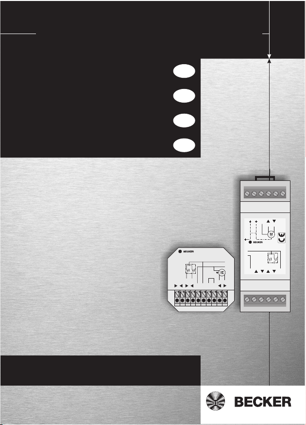
Centronic UnitControl UC42/UC45
Bedienungsanleitung
Operating Instructions
Notice d utilisation
Gebruiksaanwijzing
DE
GB
FR
NL
Einzelsteuergerät UC42
Einzelsteuergerät
für Hutschiene UC45
Individual Controller UC42
Individual Controller
for Top-Hat Rail UC45
Commande individuelle UC42
Commande individuelle
pour rail UC45
Elektronische
relaisbesturing UC 42
Zentral
Zentral
Ind.
Centronic UnitControl UC42
4031 200 010 0
230V / 50Hz / 4VA
Ind.
L
L
N
LN
Imax 5A
M
M
C
Elektronische relaisbesturing
voor montage op DIN-rail UC45
Wichtige Informationen für den Elektroanschluss.
Important information about the electric supply connection.
Informations importantes pour le branchement électrique.
Belangrijke informaties voor de elektrische aansluitingen.
N
Centronic UnitControl UC45
4031 200 011 0
L
230V/50Hz/4VA
N
Zentral
Zentral
Ind.
N
Imax 5A
C
MM
Ind.
L
Page 2

Inhaltsverzeichnis
Gewährleistung ............................................................................................. 4
Sicherheitshinweise ...................................................................................... 4
Bestimmungsgemäße Verwendung ................................................................ 5
Montage UC42 .............................................................................................. 5
Montage UC45 .............................................................................................. 5
Funktion ....................................................................................................... 5
Anschlussplan UC42 / UC45 .......................................................................... 6
Anschlussbeispiel UC42 ................................................................................ 7
Anschlussbeispiel UC45 ................................................................................ 8
Technische Daten ......................................................................................... 9
Contents
Warranty ..................................................................................................... 10
Safety instructions ...................................................................................... 10
Designated use ........................................................................................... 11
Installation UC42 ......................................................................................... 11
Installation UC45 ......................................................................................... 11
Function ..................................................................................................... 11
Connection plan UC42 / UC45 ..................................................................... 12
Connection example for UC42 ..................................................................... 13
Connection example for UC45 ..................................................................... 14
Technical Data ............................................................................................ 15
2
Page 3
Sommaire
Prestation de Garantie ................................................................................. 16
Consignes de sécurité ................................................................................. 16
Utilisation conforme aux prescriptions .......................................................... 17
Montage UC42 ............................................................................................ 17
Montage UC45 ............................................................................................ 17
Fonctionnement .......................................................................................... 17
Exemple de branchement UC42 / UC45........................................................ 18
Exemple de branchement UC42 ................................................................... 19
Exemple de branchement UC45 ................................................................... 20
Caractéristiques techniques ........................................................................ 21
Inhoudsopgave
Garantieverlening........................................................................................ 22
Veiligheidsinstructies .................................................................................. 22
Reglementair gebruik .................................................................................. 23
Montage UC42 ............................................................................................ 23
Montage UC45 ............................................................................................ 23
Functie ....................................................................................................... 23
Voorbeeld aansluiting UC42 / UC45 ............................................................. 24
Voorbeeld aansluiting UC42......................................................................... 25
Voorbeeld aansluiting UC45......................................................................... 26
Technische gegevens .................................................................................. 27
3
Page 4

Bedienungsanleitung
Inhaltsverzeichnis
Gewährleistung ............................................................................................. 4
Sicherheitshinweise ...................................................................................... 4
Bestimmungsgemäße Verwendung ................................................................ 5
Montage UC42 .............................................................................................. 5
Montage UC45 .............................................................................................. 5
Funktion ....................................................................................................... 5
Anschlussplan UC42 / UC45 .......................................................................... 6
Anschlussbeispiel UC42 ................................................................................ 7
Anschlussbeispiel UC45 ................................................................................ 8
Technische Daten ......................................................................................... 9
Gewährleistung
Becker-Antriebe GmbH ist von der gesetzlichen und vertraglichen Gewährleistung für Sachmängel und Produkthaftung befreit, wenn ohne unsere vorherige
Zustimmung eigene bauliche Veränderungen und/oder unsachgemäße Installationen gegen unsere vorgegebenen Montagerichtlinien vorgenommen, ausgeführt
oder veranlasst werden.
Der Weiterverarbeiter hat darauf zu achten, dass alle für die Herstellung und
Kundenberatung erforderlichen gesetzlichen und behördlichen Vorschriften,
insbesondere die EMV-Vorschriften, eingehalten werden.
Das vorliegende Produkt unterliegt technischen Weiterentwicklungen und Verbesserungen, informieren Sie sich in den aktuellen Verkaufsunterlagen über die
genauen Produktspezifikationen.
Sicherheitshinweise
Vorsicht
Bitte bewahren Sie die Anleitung auf!
• Nur in trockenen Räumen verwenden.
• Verwenden Sie nur unveränderte Becker Originalteile.
• Halten Sie Personen aus dem Fahrbereich der Anlagen fern.
• Halten Sie Kinder von Steuerungen fern.
• Beachten Sie Ihre landesspezifischen Bestimmungen.
4
Page 5
Bedienungsanleitung
Bestimmungsgemäße Verwendung
Die Centronic UnitControl UC42 und Centronic UnitControl UC45 sind vielseitig
verwendbare Relaissteuerungen. Sie dienen zum Ansteuern eines Rohrantriebs
mit mechanischer oder elektronischer Endabschaltung (ohne Funkempfänger),
sowie zur Ansteuerung von weiteren Folgesteuerungen. Durch die Möglichkeit
der Potentialfreischaltung der Ausgänge kann die UC42 auch zur Ansteuerung im
Niederspannungsbereich eingesetzt werden.
Montage UC42
Der typische Einbau erfolgt in der Verteilerdose neben dem Antrieb. Die Montage
kann auch in einer tiefen Verteilerschalterdose (mit mindestens 60 mm vollflächiger Tiefe) hinter einem Auf/Ab Taster erfolgen. Die Verdrahtung erfolgt gemäß Anschlußplan.
Montage UC45
Die UC45 wird innerhalb eines Kabelkanals mit integriertem Hutschienensystem
oder innerhalb eines Verteilerschranks montiert. Die Verdrahtung erfolgt gemäß
Anschlussplan.
Funktion
Der Individualbefehl erfolgt als Tippbefehl (Dauer des Befehls < 1 Sek.) oder als
Selbsthaltungsbefehl (Dauer des Befehls > 1 Sek.).
In Verbindung mit Jalousien werden Tippbefehle als Wendebefehle ausgeführt.
Der Individualbefehl wird durch einen handelsüblichen Serientaster ausgelöst.
Der Individualbefehl setzt einen Fahrbefehl von maximal 3 Minuten ab.
Der Zentralbefehl wird im Totmannbetrieb ausgeführt. Die Ansteuerung erfolgt
über vorgeschaltete Steuerungen wie Zeitschaltuhren, Sonnenwindautomaten
usw. Durch das Überordnen einer weiteren UC42/UC45 kann der Zentralbefehl in
Selbsthaltung ausgeführt werden. Auch das Bilden verschiedener Gruppenbefehle ist durch das Überordnen weiterer UC42/UC45 beliebig möglich.
Eingehende Befehle werden in folgender Reihenfolge abgearbeitet:
1. Zentralbefehl AUF
2. Zentralbefehl AB
3. Individualbefehl AUF
4. Individualbefehl AB
5
Page 6
Bedienungsanleitung
Achtung
Niemals den Antrieb parallel zu den Eingängen der UC42/UC45 schalten!
Die Installation der Steuerung darf nur durch Fachpersonal erfolgen. Bei
Nichtbeachtung haftet der Hersteller oder Anbieter nicht für entstandene Personen- oder Sachschäden, sowie für Folgeschäden.
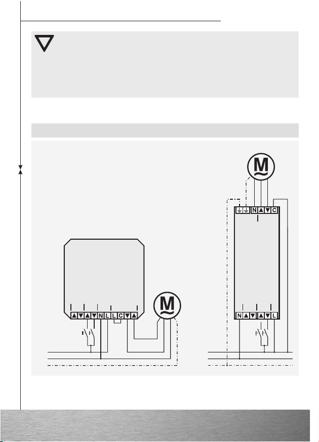
Anschlussplan UC42 / UC45
Motor
PE
UC42
Zentral
Individual
Individual
Zentral
L
N
Motor
PE
L
N
UC45
Zentral
Individual
6
Page 7
Bedienungsanleitung
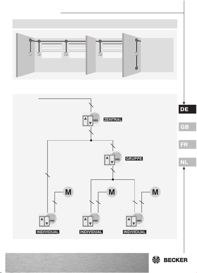
Anschlussbeispiel UC42
Individual Individual IndividualGruppe Zentral
NYM J
2
5x1,5mm
Netz
NYM J
3x1,5mm
NYM J
5x1,5mm
2
2
NYM J
5x1,5mm
NYM J
5x1,5mm
2
2
NYM J
4x1,5mm
NYM J
2
5x1,5mm
NYM J
2
4x1,5mm
NYM J
2
5x1,5mm
NYM J
4x1,5mm
2
2
7
Page 8
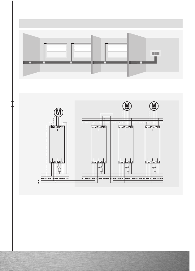
Gruppe
Zentralleitung
Gruppenleitung
Gruppe
Individual
Zentral
UC45
Motor
Individual
Zentral
UC45
Motor
Individual
Zentral
UC45
Motor
Individual
Zentral
UC45
Motor
L1
N
PE
L1
N
PE
L2
N
PE
Anschlussbeispiel UC45
Individual
Individual
Individual
Bedienungsanleitung
Schaltschrank
Zentral
Gruppe
Zentral
Individual
8
Page 9

Bedienungsanleitung
Technische Daten
CentronicCentronic
Centronic
CentronicCentronic
UnitControl UC42UnitControl UC42
UnitControl UC42
UnitControl UC42UnitControl UC42
Art.-Nr. 4031 000 003 0 4031 000 004 0
Gehäusemaße (B x H x T): 49 x 47 x 22 mm 36 x 95 x 58 mm
Schaltleistung: 5 A / 230 V AC ; 5 A / 30 V DC
Versorgungsspannung: 230 V / 50 Hz
Versorgungsstrom: 20 mA
Einsatzbereich: -40 °C ... +70 °C
Schutzart: IP30
Aufnahmeleistung: 4,6 VA
CentronicCentronic
Centronic
CentronicCentronic
UnitControl UC45UnitControl UC45
UnitControl UC45
UnitControl UC45UnitControl UC45
Technische Änderungen vorbehalten.
9
Page 10

Operating Instructions
Contents
Warranty ..................................................................................................... 10
Safety instructions ...................................................................................... 10
Designated use ........................................................................................... 11
Installation UC42 ......................................................................................... 11
Installation UC45 ......................................................................................... 11
Function ..................................................................................................... 11
Connection plan UC42 / UC45 ..................................................................... 12
Connection example for UC42 ..................................................................... 13
Connection example for UC45 ..................................................................... 14
Technical Data ............................................................................................ 15
Warranty
Becker-Antriebe GmbH will be released from all warranty and product liability obligations if the customer modifies the equipment without prior approval from
Becker-Antriebe GmbH or if the equipment is installed incorrectly and/or contrary
to the specified installation instructions, by the customer or a third party.
Any further processing must comply with all current statutory and official regulations governing manufacture and advice to customers, especially the EMC regulations.
This product is subject to technical developments and improvements. Please refer to the current sales brochure for the precise product specifications.
Safety instructions
Warning
Please keep these instructions in a safe place!
• For use in dry rooms only.
• Use unmodified Becker original parts only.
• Keep persons away from the systems guide track.
• Keep children away from controls.
• Always comply with relevant national stipulations.
10
Page 11

Operating Instructions
Designated use
The Centronic UnitControl UC42 and Centronic UnitControl UC45 are relay controls which can be used in a variety of applications. These controllers are used to
operate a tubular drive with mechanical or electronic limit switches (without radio
receiver), as well as to operate other sequential phase controls. The UC42 can
also be used in the low voltage range as the outputs can optionally be isolated.
(floating outputs)
Installation UC42
The unit is generally installed in the junction box next to the drive. Alternatively, it
can also be installed in a deep distribution circuit-breaker box (with a depth of at
least 60 mm over its entire area) behind an Up/Down switch. Wiring is effected
according to the wiring diagram.
Installation UC45
The UC45 is to be mounted in a cable duct with an integrated top-hat rail system
or inside a distribution box. Wiring must be carried out in accordance with the terminal diagram.
Function
The individual command is executed as a touch control command (duration of
command < 1 sec.) or as a self-locking command (duration of command > 1
sec.).
In conjunction with blinds, touch control commands are executed as reversing
commands. The individual command is triggered by a standard commercial serial
switch. The individual command operates in increments of 3 minutes running
time.
The central command is executed in dead man’s mode. Triggering occurs via
controls connected in series, such as programme timers, sun and wind units etc.
The connection of an additional superordinate UC42/UC45 controller allows the
central command to be executed in automatic mode. It is also possible to form
various groups by connecting further UC42/UC45 controllers.
Incoming commands are processed in the following order:
1. UP central command
2. DOWN central command
3. UP individual command
4. DOWN individual command
11
Page 12

Operating Instructions
Caution
The drive must NEVER be connected parallel to the UC42/UC45 inputs!
The control must be installed by qualified personnel. In the event of non-
observance, the manufacturer or supplier does not accept any liability
for possible personal injuries or damage to property that may arise, nor
for any consequential damages.
Connection plan UC42 / UC45
Drive
PE
UC42
Central
Individual
Individual
Central
L
N
Drive
PE
L
N
UC45
Central
Individual
12
Page 13

Operating Instructions
Connection example for UC42
Individual Individual IndividualGroup Central
NYM J
2
5x1,5mm
Mains
NYM J
3x1,5mm
NYM J
5x1,5mm
2
2
NYM J
5x1,5mm
NYM J
5x1,5mm
2
2
NYM J
4x1,5mm
NYM J
2
5x1,5mm
NYM J
2
4x1,5mm
NYM J
2
5x1,5mm
NYM J
4x1,5mm
2
2
13
Page 14

Operating Instructions
Central line
Group line
Group
Individual
Central
UC45
Drive
Individual
Central
UC45
Drive
Individual
Central
UC45
Drive
Individual
Central
UC45
Drive
L1
N
PE
L1
N
PE
L2
N
PE
Connection example for UC45
Group
Electrical Enclosure
Individual
Individual
Individual
Central
Central
Group
Individual
14
Page 15

Operating Instructions
Technical Data
CentronicCentronic
Centronic
CentronicCentronic
UnitControl UC42UnitControl UC42
UnitControl UC42
UnitControl UC42UnitControl UC42
Item no. 4031 000 003 0 4031 000 004 0
Housing dim. (WxHxD): 49 x 47 x 22 mm 36 x 95 x 58 mm
Rupturing capacity: 5 A / 230 V AC ; 5 A / 30 V DC
Supply voltage: 230 V / 50 Hz
Supply current: 20 mA
Operative range: -40 °C ... +70 °C
Protection type: IP30
Power input: 4,6 VA
CentronicCentronic
Centronic
CentronicCentronic
UnitControl UC45UnitControl UC45
UnitControl UC45
UnitControl UC45UnitControl UC45
Subject to technical changes without notice
15
Page 16

Notice d utilisation
Sommaire
Prestation de Garantie ................................................................................. 16
Consignes de sécurité ................................................................................. 16
Utilisation conforme aux prescriptions .......................................................... 17
Montage UC42 ............................................................................................ 17
Montage UC45 ............................................................................................ 17
Fonctionnement .......................................................................................... 17
Exemple de branchement UC42 / UC45........................................................ 18
Exemple de branchement UC42 ................................................................... 19
Exemple de branchement UC45 ................................................................... 20
Caractéristiques techniques ........................................................................ 21
Prestation de Garantie
Becker-Antriebe GmbH est dégagé de la garantie et de la responsabilité du fait du
produit si, sans notre autorisation préalable, des modifications de construction
sont effectuées et/ou des installations inadéquates sont exécutées ou engagées,
à l'encontre de nos directives de montage prescrites.
L'utilisateur / l'électricien doit veiller à ce que toutes les consignes et prescriptions en vigueur, particulièrement celles en matière de compatibilité électromagnétique, soient respectées.
Le présent produit est soumis à des développements et perfectionnements techniques, informez-vous dans les documents de vente actuels au sujet des spécifications de produit précises.
Consignes de sécurité
Prudence
Prière de conserver ces instructions d’utilisation!
• A utiliser uniquement dans des locaux secs.
• Utilisez uniquement des pièces originales de Becker n’ayant subi
aucune modification.
• Veillez à ce que personne ne se tienne dans la zone de déploiement des
installations
• Tenez les enfants à l’écart des commandes.
• Observez les directives spécifiques de votre pays.
16
Page 17

Notice d utilisation
Utilisation conforme aux prescriptions
La Centronic UnitControl UC42 et la Centronic UnitControl UC45 sont des commandes relais utilisables de façon multiple. Elles servent à commander un moteur
tubulaire avec fin de course mécanique ou électronique (sans récepteur radio),
ainsi qu’à commander d’autres commandes successives. Grâce à la possibilité
de libération de potentiel des sorties, la UC42 peut également être utilisée dans
une zone à basse tension.
Montage UC42
Le montage typique est effectué dans le distributeur placé à côté du moteur. Il
peut également être réalisé dans un distributeur-commutateur profond (profondeur minimale sur toute la surface: 60 mm) derrière une touche MONTÉE/ DESCENTE. Le câblage s’effectue conformément au plan des connexions.
Montage UC45
La commande UC45 est montée à l’intérieur d’une conduite de câbles avec rail
intégré ou à l’intérieur d’une armoire électrique. Le câblage s’effectue conformément au plan de branchement.
Fonctionnement
La commande individuelle s’effectue comme commande tapée (durée < 1 sec., mouvement aller-retour du moteur) ou comme commande automatique (durée >
1 sec. - le moteur marche jusqu’à la position finale).
Combinées avec des volets roulants, les commandes tapées ont pour effet un
changement de direction du volet roulant. La commande individuelle est déclenchée par une inverseur sériel. La commande individuelle reste active pendant 3
minutes.
La commande centrale est effectuée en mode homme mort (la touche doit être
maintenue appuyée). Le contrôle des moteurs s’effectue par des appareils
comme par exemple des horloges ou des automatismes soleil et vent associés.
En plaçant au niveau supérieur une autre UC42/UC45, la commande centrale
peut être exécutée en position de maintien maintenue. La formation de différents
groupes est également possible en plaçant au niveau supérieur autant de UC42/
UC45 que l’on souhaite.
Exécution des commandes dans l’ordre suivant :
1. Commande centrale MONTEE
2. Commande centrale DESCENTE
3. Commande individuelle MONTEE
4. Commande individuelle DESCENTE
17
Page 18

Notice d utilisation
Attention
Ne jamais brancher le moteur parallèlement aux entrées UC42/UC45 !
L’installation de la commande ne doit être réalisée que par du personnel
qualifié. En cas de non-respect, le fabricant ou le revendeur n’assument
aucune garantie pour les dommages corporels ou matériels, ainsi que
pour les dommages consécutifs.
Exemple de branchement UC42 / UC45
Moteur
PE
UC42
Central
Individuelle
Individuelle
Central
L
N
Moteur
PE
L
N
UC45
Central
Individuelle
18
Page 19

Notice d utilisation
Exemple de branchement UC42
Individuelle Individuelle IndividuelleGroupe Centrale
NYM J
2
5x1,5mm
Réseau
NYM J
3x1,5mm
NYM J
5x1,5mm
2
2
NYM J
5x1,5mm
NYM J
5x1,5mm
2
2
NYM J
4x1,5mm
NYM J
2
5x1,5mm
NYM J
2
4x1,5mm
NYM J
2
5x1,5mm
NYM J
4x1,5mm
2
2
19
Page 20

Notice d utilisation
Ligne centrale
Ligne de groupe
Groupe
Individuelle
Central
UC45
Moteur
Individuelle
Central
UC45
Moteur
Individuelle
Central
UC45
Moteur
Individuelle
Central
UC45
Moteur
L1
N
PE
L1
N
PE
L2
N
PE
Exemple de branchement UC45
Groupe
Individuelle
Armoire électrique
Individuelle
Individuelle
Centrale
Centrale
Groupe
Individuelle
20
Page 21

Notice d utilisation
Caractéristiques techniques
CentronicCentronic
Centronic
CentronicCentronic
UnitControl UC42UnitControl UC42
UnitControl UC42
UnitControl UC42UnitControl UC42
Réf. article: 4031 000 003 0 4031 000 004 0
Dim. de la boîte (lxHxP): 49 x 47 x 22 mm 36 x 95 x 58 mm
Puissance de rupture: 5 A / 230 V AC ; 5 A / 30 V DC
Tension d’alimentation: 230 V / 50 Hz
Intensité du courant d’alimentation: 20 mA
Plage d’utilisation: -40 °C ... +70 °C
Type de protection: IP30
Puissance absorbée: 4,6 VA
CentronicCentronic
Centronic
CentronicCentronic
UnitControl UC45UnitControl UC45
UnitControl UC45
UnitControl UC45UnitControl UC45
Sous réserve de modifications techniques
21
Page 22

Gebruiksaanwijzing
Inhoudsopgave
Garantieverlening ........................................................................................ 22
Veiligheidsinstructies .................................................................................. 22
Reglementair gebruik .................................................................................. 23
Montage UC42 ............................................................................................ 23
Montage UC45 ............................................................................................ 23
Functie ....................................................................................................... 23
Voorbeeld aansluiting UC42 / UC45 ............................................................. 24
Voorbeeld aansluiting UC42......................................................................... 25
Voorbeeld aansluiting UC45......................................................................... 26
Technische gegevens .................................................................................. 27
Garantieverlening
Becker-Antriebe GmbH is van de garantieverlening en de productaansprakelijkheid bevrijd, wanneer zonder onze voorafgaande toestemming eigen bouwkundige constructie-wijzigingen zijn aangebracht en/of onvakkundige
installaties worden doorgevoerd of in opdracht worden gegeven, die in strijd zijn
met onze voorgeschreven montagerichtlijnen.
De verdere verwerker dient erop toe te zien dat alle voor het tot stand brengen van
en het adviseren van de consument vereiste wettelijke en officiele voorschriften in
acht worden genomen.
Dit product is onderhevig aan technische ontwikkelingen en verbeteringen. Voor
de nadere productspecificaties verwijzen wij naar de actuele verkoopdocumentatie.
Veiligheidsinstructies
Voorzichtig
De handleiding goed bewaren!
• Uitsluitend in droge ruimte gebruiken.
• Gebruik uitsluitend niet veranderde originele onderdelen van Becker.
• Houd personen buiten het werkgebied van de installatie.
• Houd kinderen op afstand van besturingsapparaten.
• Neem de bepalingen in acht die specifiek voor uw land van toepassing
zijn.
22
Page 23

Gebruiksaanwijzing
Reglementair gebruik
De Centronic UnitControl UC42 en de Centronic UnitControl UC45 zijn veelzijdig
toepasbare relaisbesturingen. Deze besturingen dienen voor het aansturen van
een buismotor met mechanische of elektronische eindschakelaar (zonder draadloze ontvanger), alsmede voor het aansturen van toegevoegde besturingen.
Doordat het mogelijk is de uitgangen potentiaal vrij te schakelen, kan de UC42
ook worden gebruikt voor de aansturing in het laagspanningsbereik.
Montage UC42
De standaardinbouw gebeurt in een verdeeldoos naast de aandrijving. De montage kan ook gebeuren in een diepe inbouwdoos (met minstens 80 mm diepte
over het volledige oppervlak) achter een OMHOOG/OMLAAG-schakelaar. De bedrading gebeurt overeenkomstig het aansluitschema.
Montage UC45
Monteer de UC45 in een kabelgoot met geïntegreerd DIN-railsysteem of in een
verdelerkast. De bedrading wordt volgens aansluitschema aangelegd.
Functie
De individuele instructie gebeurt als tipinstructie (duur van de instructie < 1 sec.)
of als zelfvergrendelende instructie (duur van de instructie > 1 sec).
In combinatie met jaloezieën worden tipinstructies uitgevoerd als keerinstructies.
De individuele instructie wordt geactiveerd door een gangbare serieschakelaar.
Het individuele commando heeft een looptijd van 3 minuten.
De centrale instructie wordt uitgevoerd in dodemansmodus. De aansturing gebeurt via voorgeschakelde besturingen, zoals schakelklokken, zon-wind-automaten enz. Door het plaatsen van een tussenliggende UC42/UC45 kan het centrale
commando als duurcommando worden uitgevoerd. Naar wens is het ook mogelijk
om door het plaatsen van meer toegevoegde UC42/US45‘s meer groepen te vormen.
Binnenkomende instructies worden in onderstaande volgorde afgewerkt:
1. Centrale instructie OMHOOG
2. Centrale instructie OMLAAG
3. Individuele instructie OMHOOG
4. Individuele instructie OMLAAG
23
Page 24

Gebruiksaanwijzing
Opgelet
Schakel een motor nooit parallel aan de ingangen van een toegevoegde
UC42/UC45!
De installatie van de besturing mag uitsluitend uitgevoerd worden door
geschoold personeel. Bij niet-inachtneming kan de fabrikant of aanbieder niet aansprakelijk gesteld worden voor ontstane lichamelijke of
materiële schade of voor gevolgschade.
Voorbeeld aansluiting UC42 / UC45
Motor
PE
UC42
Centraal
Individueel
Individueel
Centraal
L
N
Motor
PE
L
N
UC45
Centraal
Individueel
24
Page 25

Gebruiksaanwijzing
Voorbeeld aansluiting UC42
Individueel Individueel IndividueelGroep Centraal
NYM J
2
5x1,5mm
NYM J
3x1,5mm
NYM J
5x1,5mm
Net
2
2
NYM J
5x1,5mm
NYM J
5x1,5mm
2
2
NYM J
4x1,5mm
NYM J
2
5x1,5mm
NYM J
2
4x1,5mm
NYM J
2
5x1,5mm
NYM J
4x1,5mm
2
2
25
Page 26

Groep
Centrale
ringleiding
Bekabeling
voor
groepsbesturing
Groep
Individueel
Centraal
UC45
Motor
Individueel
Centraal
UC45
Motor
Individueel
Centraal
UC45
Motor
Individueel
Centraal
UC45
Motor
L1
N
PE
L1
N
PE
L2
N
PE
Voorbeeld aansluiting UC45
Individueel
Individueel
Individueel
Gebruiksaanwijzing
Schakelkast
Central
Groep
Central
Individueel
26
Page 27

Gebruiksaanwijzing
Technische gegevens
CentronicCentronic
Centronic
CentronicCentronic
UnitControl UC42UnitControl UC42
UnitControl UC42
UnitControl UC42UnitControl UC42
Art.-nr.: 4031 000 003 0 4031 000 004 0
Behuizingsafmetingen (BxHxD): 49 x 47 x 22 mm 36 x 95 x 58 mm
Schakelvermogen: 5 A / 230 V AC ; 5 A / 30 V DC
Voedingsspanning: 230 V / 50 Hz
Voedingsstroom: 20 mA
Toepassingsgebied: -40 °C ... +70 °C
Isolatieklasse: IP30
Vermogensopname: 4,6 VA
CentronicCentronic
Centronic
CentronicCentronic
UnitControl UC45UnitControl UC45
UnitControl UC45
UnitControl UC45UnitControl UC45
Technische wijzigingen voorbehouden
27
Page 28

BeckerAntriebe GmbH
35764 Sinn/Germany
4031 630 007 0a 08/04 DE/GB/FR/NL
 Loading...