

Page 1

BECK-O-TRONIC 4
Version: Centronic
en Assembly and Operating Instructions
Door control unit
Important information for:
• Fitters / • Electricians / • Users
Please forward accordingly!
These instructions must be kept safe for future reference.
Becker-Antriebe GmbH
Friedrich-Ebert-Straße 2-4
35764 Sinn/Germany
www.becker-antriebe.com
Page 2

Table of contents
Contents .............................................................................................................. 3
General ............................................................................................................... 3
Warranty .............................................................................................................. 4
Safety instructions ................................................................................................ 5
Intended use ........................................................................................................ 6
Explanation of displays and buttons ....................................................................... 7
Programming the remote control ........................................................................... 8
Deleting transmitters ............................................................................................ 9
Overwriting the master transmitter ......................................................................... 9
Installation .......................................................................................................... 10
Wiring ................................................................................................................. 10
Configuration ...................................................................................................... 11
Maintenance ....................................................................................................... 15
Cleaning ............................................................................................................. 16
Technical data ..................................................................................................... 17
Connecting diagram ............................................................................................ 18
Declaration of conformity ..................................................................................... 19
2
Page 3
Contents
General
This control unit is a high-quality product with many features and advantages:
▪ simple, convenient connection
▪ easy to handle and highly flexible
▪ automatic limit position detection
▪ defined buttons for UP, STOP and DOWN, also on the hand-held transmitter
▪ modular system thanks to plug-in radio and sensors
▪ design with clear display of operating status and error messages
▪ optical safety edge connectable without external sensor
Please observe these Assembly and Operating Instructions when installing and setting
the equipment.
Caution
Denotes a potentially hazardous situation. If this is not
avoided, injuries may result.
Attention
Denotes a potentially hazardous situation. If this is not
avoided, the product or something in its vicinity may be
damaged.
Note
Denotes user tips and other useful information.
3
Page 4

Warranty
Structural modifications and incorrect installation which are not in accordance with
these and our other instructions can result in serious injuries, e.g., crushing of limbs.
Therefore, structural modifications may only be carried out with our prior approval and
strictly in accordance with our instructions, particularly the information contained in
these Assembly and Operating Instructions.
Any further processing of the products which does not comply with their intended use is
not permitted.
The end product manufacturer and fitter have to ensure that all the relevant current
statutory, official and, in particular, EMC regulations are adhered to during utilisation of
our products, especially with regard to end product manufacture, installation and cus‐
tomer advice.
4
Page 5

Safety instructions
The following safety instructions and warnings are intended to avert hazards and to
prevent property damage and personal injury.
Please keep the instruction manual safe!
Caution
▪ Work on the electrical equipment may only be carried out by a quali‐
fied electrician.
▪ Ensure compliance with legal provisions (safety, accident preven‐
tion), in particular the provisions of the employers’ liability insur‐
ance associations (BGR 232) and EN 12453 “Safety in use of power
operated doors” as well as the pertinent VDE and EN standards.
▪ The engineer responsible for fitting the system must ensure proper
installation, instruction of the operator in its use and issue of the CE
mark.
▪ The operator must ensure that the system is only operated in per‐
fect condition and that the safety devices are checked regularly by
an expert to ensure they are in full working order.
▪ A damaged mains connecting cable must be replaced immediately
by a qualified electrician.
▪ When using roller doors, the customer must ensure that the roller
shutter curtain is protected and cannot cause any dangerous situa‐
tions, e.g. by overrunning a limit position.
▪ The control unit is designed to have a service life of 100,000 operat‐
ing cycles.
▪ Drives with a H05VV-F connecting cable may only be used indoors. If
the cable is installed outdoors, it must be placed in a protective
conduit.
5
Page 6

Intended use
The type of control unit described in these instructions may only be used for the opera‐
tion of tubular drives in roller doors which have fixed stops at the limit positions or a
cover on the barrel (EN 12453). The radio receiver can be operated using any transmit‐
ter of the Centronic range of control units (with the exception of transmitters with a time
switching function and / or sun protection function). For travel in the DOWN direction in
maintained operation, a closing edge safety device is necessary.
This type of control unit must not be used in potentially explosive areas.
Other applications, uses and modifications are not permitted in order to protect the
safety of the users and others, since these actions can impair the system’s safety and
carry the risk of personal injury and property damage. The manufacturer does not ac‐
cept liability for damage or injury arising from such actions.
Always observe the information in these instructions when operating or repairing the
system. The manufacturer does not accept liability for damage or injury resulting from
improper use.
6
Page 7

Explanation of displays and buttons
FUNK
A
C
E
B
D
F
A) Radio-PRG button
B) Programming button on the radio re‐
ceiver
C) Programming button on the transmit‐
ter
D) LED
E) Channel selection button
F) DIP switch
(DIP ON: Defined travel buttons Up, Stop,
Down
DIP OFF: Pulse sequence Up – Stop –
Down – Stop etc.)
7
Page 8

Programming the remote control
Note
Operate the programming button on the transmitter using a suitable
cylindrical tool (e.g. a ballpoint pen).
Programming the first transmitter (master transmitter)
Press the programming button on the radio receiver (B) for 3 seconds.
[ The LED (D) flashes and the radio receiver goes into programming mode for 3
minutes.
Then press the programming button on the transmitter (C) for 3 seconds.
[ The LED on the hand-held transmitter lights up for 3 seconds and the LED (D)
goes out.
Æ Programming is thereby completed and the control unit switches back to the normal
operating status.
Now close the cover of the control unit again using the four cover screws.
Programming additional transmitters
Note
In addition to the master transmitter, up to 7 further transmitters can
be programmed in the radio receiver.
Press the programming button (C) of the master transmitter for 3 seconds.
[ The LED (D) lights up once to confirm.
Now press the programming button of a new transmitter which has not yet been pro‐
grammed in the radio receiver for 3 seconds. This activates the programming mode of
the radio receiver for a new transmitter for 3 minutes.
[ The LED (D) lights up once to confirm.
Now press the programming button of the new transmitter again for 3 seconds.
[ The LED (D) lights up twice to confirm.
Æ The new transmitter has now been programmed.
8
Page 9

Deleting transmitters
Deleting individual transmitters
Note
The programmed master transmitter cannot be deleted. It can only be
overwritten.
Press the programming button (C) on the master transmitter for 3 seconds.
[ The LED (D) lights up once to confirm.
Now press the programming button of the transmitter to be deleted for 3 seconds.
[ The LED (D) lights up once to confirm.
Then press the programming button of the transmitter to be deleted again for 10 sec‐
onds.
[ The LED (D) lights up twice to confirm.
Æ The transmitter has now been deleted from the radio receiver.
Deleting all transmitters (except the master transmitter)
Press the programming button (C) on the master transmitter for 3 seconds.
[ The LED (D) lights up once to confirm.
Press the programming button (C) on the master transmitter again for 3 seconds.
[ The LED (D) lights up once to confirm.
Press the programming button (C) on the master transmitter again for 10 seconds.
[ The LED (D) lights up twice to confirm.
Æ All transmitters (except the master transmitter) have now been deleted from the ra‐
dio receiver.
Overwriting the master transmitter
Press the programming button on the radio receiver (B) for 3 seconds.
[ The LED (D) flashes and the radio receiver goes into programming mode for 3
minutes.
Now press the programming button of the new master transmitter for 10 seconds.
[ This is confirmed by the LED (D) going out.
Æ The new master transmitter has now been programmed and the old master trans‐
mitter overwritten.
9
Page 10

Installation
Open the cover of the control unit. Unplug and remove the keyboard overlay from the
control unit and carefully place the cover to one side.
Remove the required cut-outs in the bottom part of the housing.
Note
Cut in at the edges to make the cut-outs easier to remove.
Use the enclosed cardboard drilling template to drill the holes for attaching the housing
to the wall.
Wiring
Connection of the motor, outdoor light/advance warning light, light barrier, ex‐
ternal key-operated push-button and bottom rail sensor
Connect the individual pieces of equipment as shown in the connecting diagram.
Caution
Electrical work may only be carried out by qualified electricians or
trained personnel. Always disconnect the safety mains plug before
connecting the equipment.
Note
First, pull the insert sleeves over the connecting cable and then push
the insert sleeves into the bottom part of the housing once all of the
wires have been connected.
10
Page 11

Configuration
1
1
4
72
5
83 6
ON
DIP
1
4
72
5
83 6
ON
DIP
1
2
3
1
4
7
2
5
83 6
ON
DIP
Using the 8 DIP switches (1), you can configure the con‐
trol unit according to your requirements:
▪ Mode
▪ Closing edge safety device
▪ Outdoor light or advance warning light
▪ Automatic closing
Factory settings
Dead-man operating mode factory setting:
Maintained operation mode factory setting:
(only with safety contact rail sensor):
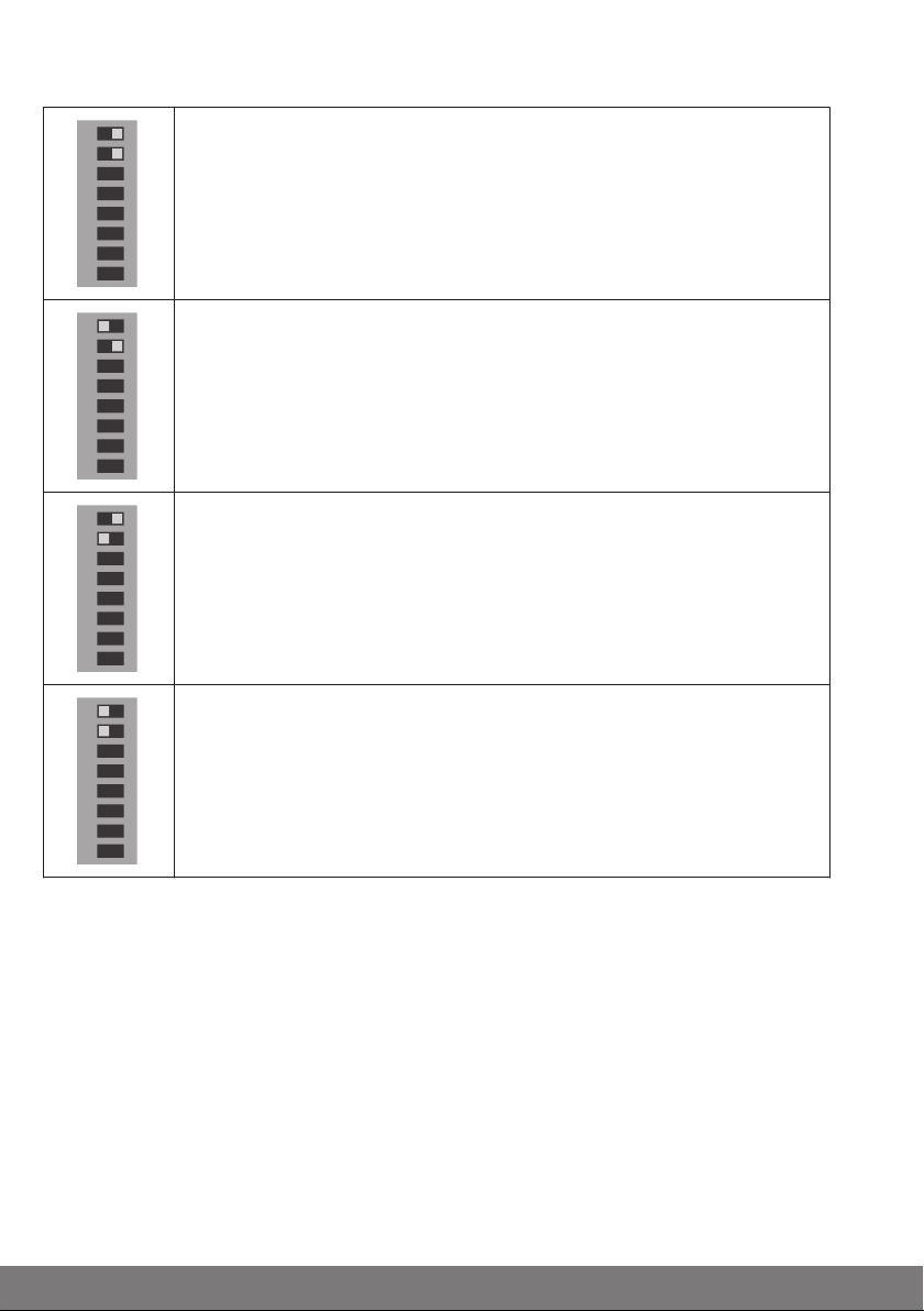
Operating mode
Setting mode
Limit position detection and running time monitoring are off. The con‐
trol unit does not switch off the power to the tubular drive once a limit
position has been reached, so the limit position of the door system can
be adjusted while it is live. This ensures that the door system directly
follows the settings of the limit switches. To disconnect from the power
supply, press the STOP button.
Attention
The setting mode is only suitable for tubular drives with mechanical
limit switching. Once the settings are complete, DIP switch 1 must be
set to OFF (door mode). Operating the door in the setting mode is not
permitted!
11
Page 12

1
4
7
2
5
83 6
ON
DIP
Door mode
1
4
7
2
5
83 6
ON
DIP
1
4
7
2
5
83 6
ON
DIP
1
4
7
2
5
83 6
ON
DIP
1
4
7
2
5
83 6
ON
DIP
The control unit is ready for operation. Limit position detection and run‐
ning time monitoring are on.
Closing edge safety device
Caution
In the maintained operation mode, the system must be equipped with a
safety contact rail. The sensor of the safety contact rail must be fitted.
Please ensure that main and auxiliary closing edges are adequately se‐
cured and that the permitted closing edge forces are not exceeded!
Dead-man mode
The door can only be controlled using hard-wired device (e.g. pushbutton). In the DOWN direction, the DOWN button must be permanently
held down. In the UP direction, the door travels in maintained opera‐
tion. The hand-held transmitter can only be used for travel in the UP di‐
rection.
Closing edge stop mode
While the door is closing, the light barrier or safety edge is activated.
The door stops as soon as the safety edge is activated or the light barri‐
er is interrupted. No function in the UP direction. After encountering an
obstruction, the door must first clear the obstruction before it can be
lowered again.
Closing edge reverse travel mode (clearing an obstruction)
While the door is closing, the light barrier or safety edge is activated.
The door stops and reverses as soon as the safety edge is activated or
the light barrier is interrupted. No function in the UP direction.
Closing edge reopening travel mode
While the door is closing, the light barrier or safety edge is activated.
The door stops and travels to the upper limit position as soon as the
safety edge is activated or the light barrier is interrupted. No function in
the UP direction.
12
Page 13

1
4
7
2
5
83 6
ON
DIP
1
4
7
2
5
83 6
ON
DIP
1
4
7
2
5
83 6
ON
DIP
1
4
7
2
5
83 6
ON
DIP
1
4
7
2
5
83 6
ON
DIP
1
4
7
2
5
83 6
ON
DIP
Outdoor light or advance warning light
Outdoor light mode
The light is switched on for 2 minutes at every door movement. The
light can also be switched on via the stop or radio light button (with the
4-channel hand-held transmitter).
Automatic staircase lighting
A connected automatic staircase light is triggered for 2 seconds at ev‐
ery door movement. The light can also be switched on via the stop or
remote light button (with the 4-channel hand-held transmitter).
General advance warning
An advance warning is given for 3 seconds before every door move‐
ment. The warning light is only switched off again once a limit position
has been reached.
Advance warning for automatic closing
An advance warning is given for 3 seconds before every automatic clo‐
sure. The warning light is only switched off again once a limit position
has been reached.
Type of warning light: Automatic flashing warning light
e.g.: Rotating beacon.
Type of warning light: Pulsed warning light
The warning light does not flash automatically, so in order to create a
flashing effect, the output is pulsed at 1 Hz.
13
Page 14
1
4
7
2
5
83 6
ON
DIP
1
4
7
2
5
83 6
ON
DIP
1
4
7
2
5
83 6
ON
DIP
1
4
7
2
5
83 6
ON
DIP
Automatic closing
Automatic closing deactivated.
Automatic closing without light barrier reduction
The door closes after a delay of 1 minute. If the door encounters an ob‐
struction, automatic closing is aborted after 5 unsuccessful attempts.
The door must then be moved to the lower limit position using the but‐
tons on the control unit or a hard-wired device.
Automatic closing with light barrier reduction to 3 seconds
The door is closed after a delay of 1 minute. This time is reduced to 3
seconds by passing the light barrier. If the door encounters an obstruc‐
tion, automatic closing is aborted after 5 unsuccessful attempts. The
door must then be moved to the lower limit position using the buttons
on the control unit or a hard-wired device.
Automatic closing with light barrier reduction to 15 seconds
The door is closed after a delay of 1 minute. This time can be reduced
to 15 seconds by passing the light barrier. If the door encounters an
obstruction, automatic closing is aborted after 5 unsuccessful at‐
tempts. The door must then be moved to the lower limit position using
the buttons on the control unit or a hard-wired device.
14
Page 15

Sensors for safety edges
12
1
2
3
1
2
3
1
2
3
1
2
3
1
2
3
1. DIP switch
USA (bottom rail sensor)
configuration
2. Sensor
Safety edge with 1k2 Ohm terminating resistor without testing
Safety edge with 1k2 Ohm terminating resistor with testing
The safety edge is tested during every closing movement: Once the
pre-limit switch is activated, the safety edge must be activated within 2
seconds (positive testing)
These settings are only possible if the plug-in sensor for
the safety edges is fitted.
Pneumatic safety edges are tested for safety-related
reasons during every downward movement. This proc‐
ess is called testing.
Safety edge with 8k2 Ohm terminating resistor without testing
Safety edge with 8k2 Ohm terminating resistor with testing
The safety edge is tested during every closing movement: Once the
pre-limit switch is activated, the safety edge must be activated within 6
seconds (positive testing)
Optical edge from Fraba
Note
With pneumatic safety edges (testing), a pre-limit switch (Item no.
4932 100 012 0) must always be connected.
Maintenance
This control unit is maintenance-free.
15
Page 16

Cleaning
Only clean the outside of the housing with a suitable cloth. Do not use cleaning agents,
as these may damage the plastic.
16
Page 17

Technical data
Dimensions of the housing (W x H x D) 155 x 130 x 50 mm
Housing material PC
Degree of protection IP54, only for installation indoors
Supply voltage 230 V / 50 Hz (connection type Y)
Input power 6 V A
Fuse 2 A slow-blow
Drive switching capacity 1 drive 230 V / 50 Hz maximum 260 V A
Light switching capacity 230 V / 50 Hz maximum 100 W
Control voltage 24 V maximum 100 mA
Temperature range -10°C to +50°C
Radio frequency 868.3 MHz
17
Page 18

Connecting diagram
Radio
USA sensor
Electric
safety edge
Pneumatic safety
edge contact
Pre-limit switch
Light barrier
Motor
white
green
brown
Outdoor light
Warning light
e.g.,
key switch
Emergency stop circuit
or anti-unrolling device
Optical safety edge
from FRABA
External pre-limit switch
for the initiation of testing
at the pneumatic safety edge contact.
Keypad
Radio PRG Em. Stp.
18
Page 19

Declaration of conformity
19
Page 20

4005 630 034 0 30/01/2013
 Loading...