

Page 1

CentralControl
CC51, CC31
en
Assembly and operating instructions for operation with the local interface
Central controller
Important information for:
• Fitters / • Electricians / • Users
Please forward accordingly!
These instructions must be kept safe for future reference.
4035 630 147 025/07/2017
Becker-Antriebe GmbH
Friedrich-Ebert-Straße 2-4
35764 Sinn/Germany
www.becker-antriebe.com
Page 2

Table of contents
General ................................................................................................................ 5
Warranty .............................................................................................................. 5
Items included ...................................................................................................... 6
Safety instructions ................................................................................................ 6
Intended use ........................................................................................................ 8
Dimensions .......................................................................................................... 9
Device overview ...................................................................................................10
Start / standard screen.........................................................................................13
Mains connection ................................................................................................14
Explanation of pictograms ....................................................................................14
Explanation of the operator controls ......................................................................16
Operating the house automation with other devices on the home network.................17
Operating the house automation through a device with mobile Internet access from
outside................................................................................................................18
Preparing to commission the CC31 .......................................................................18
Commissioning with the local interface ..................................................................20
Setting the language ...................................................................................... 20
Establishing a network connection................................................................... 21
Setting the time and date................................................................................ 21
Setting the location ........................................................................................ 22
Adding a Centronic receiver ............................................................................ 22
Adding a B-Tronic receiver ............................................................................. 23
Adding a room ............................................................................................... 23
Adding elements to a room ............................................................................. 23
End of commissioning .................................................................................... 23
Building wiring system settings .............................................................................24
Adding a Centronic receiver ............................................................................ 24
Adding a B-Tronic receiver ............................................................................. 24
Deleting a Centronic receiver .......................................................................... 25
Deleting a B-Tronic receiver............................................................................ 25
Renaming a receiver ...................................................................................... 26
Adding a Centronic or B-Tronic transmitter ...................................................... 26
Deleting a Centronic or B-Tronic transmitter .................................................... 26
Renaming a transmitter .................................................................................. 26
Adding a Centronic or B-Tronic sensor ............................................................ 26
Deleting a Centronic or B-Tronic sensor .......................................................... 26
Renaming a sensor ........................................................................................ 26
Adding an internal object ................................................................................ 26
Deleting an internal object .............................................................................. 26
Renaming an internal object............................................................................ 26
Linking a transmitter to a function (adding logic)............................................... 26
Linking a sensor to a function (adding logic) ..................................................... 26
Linking an internal object to a function (adding logic) ........................................ 26
2
Page 3

My Home settings ................................................................................................27
Adding a room ............................................................................................... 27
Sorting rooms................................................................................................ 27
Deleting a room ............................................................................................. 27
Renaming a room........................................................................................... 27
Allocating elements to a room ......................................................................... 28
Sorting elements in a room ............................................................................. 28
Deleting elements from a room ....................................................................... 28
Adding a group .............................................................................................. 28
Sorting groups............................................................................................... 29
Deleting a group ............................................................................................ 29
Renaming a group.......................................................................................... 29
Allocating elements to a group ........................................................................ 29
Deleting elements from a group ...................................................................... 30
Adding a scenario .......................................................................................... 30
Sorting scenarios........................................................................................... 31
Deleting a scenario ........................................................................................ 31
Renaming a scenario...................................................................................... 31
Allocating elements to a scenario .................................................................... 31
Deleting elements from a scenario .................................................................. 32
Adding a camera............................................................................................ 32
Sorting cameras ............................................................................................ 32
Deleting a camera .......................................................................................... 32
Changing camera settings .............................................................................. 33
Adding a radio ............................................................................................... 33
Sorting radios ................................................................................................ 33
Deleting a radio.............................................................................................. 33
Changing radio settings.................................................................................. 34
Automation settings .............................................................................................34
Setting the memory function (ON/OFF)............................................................ 34
Setting the automatic roof window................................................................... 35
Setting the holiday function............................................................................. 35
Setting the sun protection function .................................................................. 36
Adding a timer ............................................................................................... 36
Changing a timer............................................................................................ 36
Deleting a timer ............................................................................................. 37
Setting the heating functions........................................................................... 37
Access settings ...................................................................................................38
Generating a service code .............................................................................. 38
Setting up remote access for an existing account ............................................. 39
Setting up remote access for a new account .................................................... 40
View settings .......................................................................................................41
Setting the background colour ........................................................................ 41
Setting the visual background effects .............................................................. 41
3
Page 4

Resetting the background colour and the visual background effects to the factory
settings ......................................................................................................... 41
Information settings .............................................................................................41
System information ........................................................................................ 41
Reading out the error memory ........................................................................ 41
Reading update news ..................................................................................... 42
System settings ...................................................................................................42
Setting the language ...................................................................................... 42
Setting the location ........................................................................................ 42
Setting the time and date................................................................................ 43
Establishing a network connection................................................................... 43
Update.......................................................................................................... 44
Creating a backup.......................................................................................... 44
Restoring from backup ................................................................................... 45
Factory reset ................................................................................................. 45
Reboot.......................................................................................................... 45
Rooms ................................................................................................................46
Setting receivers to Automatic mode ............................................................... 46
Setting all the receivers in the room to Automatic mode..................................... 46
Setting all the receivers in the home to Automatic mode .................................... 46
Setting receivers to Manual mode ................................................................... 46
Setting all the receivers in the room to Manual mode......................................... 46
Setting all the receivers in the home to Manual mode ........................................ 47
Operating receivers........................................................................................ 47
Adding favourites ........................................................................................... 47
Deleting favourites ......................................................................................... 47
Groups................................................................................................................48
Operating groups........................................................................................... 48
Scenarios............................................................................................................48
Operating scenarios....................................................................................... 48
Cameras .............................................................................................................48
Calling up cameras ........................................................................................ 48
Radios ................................................................................................................48
Starting a radio .............................................................................................. 48
Stopping a radio ............................................................................................ 49
Weather forecast .................................................................................................49
Changing the batteries of an external keyboard ......................................................49
Cleaning..............................................................................................................49
Technical data .....................................................................................................50
Technical data for the CC51............................................................................ 50
Technical data for the CC31............................................................................ 51
What to do if...?....................................................................................................52
Simplified EU declaration of conformity..................................................................53
Annex .................................................................................................................53
Astronomical function..................................................................................... 53
4
Page 5

General
With the B-Tronic CentralControl you can operate the drives and control units with bidirectional KNX radio and the Centronic I and II range of controls.
This device uses free/open source software. The source code can be downloaded from
http://www.b-tronic.net/source/. On request, Becker Antriebe will make the source
code available on a CD-ROM at cost price. Please contact source@b-tronic.net if you
are interested.
As a result of continuous further development of the software, there can be differences
between the illustrations and your device.
This is not, however, important for any of the procedures described.
Please observe these Assembly and Operating Instructions when installing and setting
up the equipment.
Warranty
Structural modifications and incorrect installation which are not in accordance with
these and our other instructions can result in serious injuries, e.g., crushing of limbs.
Therefore, structural modifications may only be carried out with our prior approval and
strictly in accordance with our instructions, particularly the information contained in
these Assembly and Operating Instructions.
Any further processing of the products which does not comply with their intended use is
not permitted.
The end product manufacturer and fitter have to ensure that all the relevant current
statutory, official and, in particular, EMC regulations are adhered to during utilisation of
our products, especially with regard to end product manufacture, installation and customer advice.
5
Page 6
Items included
CC51 CC31
• B-Tronic CentralControl control unit
• USB WLAN stick
• USB Flash memory stick
• USB Centronic stick
• USB B-Tronic/KNX stick
• Mains adapter
• Fasteners for wall mounting
• Commissioning instructions
• B-Tronic CentralControl control unit
• Flash memory SD card
• USB Centronic stick
• USB B-Tronic/KNX stick
• Mains adapter
• Wireless keypad (incl. USB receiver
stick and batteries)
• Commissioning instructions
Safety instructions
General information
• Please keep the instructions safe!
• Only use in dry rooms.
• Keep people out of the system’s range of travel.
• Keep children away from control units.
• Observe all pertinent country-specific regulations.
• Do not place any objects on the control unit.
• Clean the control unit with a soft, dry, lint-free cloth, and do not use
any chemical cleaning agents.
Caution
• If the system is controlled by one or more transmitters,
the system’s range of travel must always be visible during operation.
• Keep packaging materials such as film away from chil-
dren. Misuse can create the risk of suffocation.
6
Page 7

• Switch the control unit off immediately if the mains ad-
apter and the plug to which it is connected is burnt or
damaged. If a mains adapter is damaged, replace it with
an original one. A faulty mains adapter must not under
any circumstances be repaired.
• Switch the control unit off immediately if the housing of
the control unit is damaged, or if liquids have penetrated.
Attention
• Do not let any objects fall onto the control unit.
• If a display is present, protect it against being scratched
by hard objects (e.g. rings, fingernails, wristwatches)
• Wait until the control unit has adjusted to ambient tem-
perature before connecting the control unit to the mains
adapter. Condensation that could lead to a short circuit
can be caused inside the control unit by large differences in temperature and air humidity.
7
Page 8

Intended use
The B-Tronic CentralControl may only be used for the operation of suitable drives and
control units with bidirectional KNX radio and with the Centronic I and II range of controls. You can operate a group, or multiple groups, of devices with this controller.
• Please note that radio-controlled systems may not be used in areas
with a high risk of interference (e.g. hospitals, airports).
• The remote control is intended solely for use with equipment and
systems in which malfunctions in the transmitter or receiver would
not pose any risk to persons, animals or property, or which contain
safety devices to eliminate such risks.
• The operator is not protected from interference from other telecom-
munications systems and terminal equipment (e.g. even from radiocontrolled systems which are properly operated in the same frequency range).
• Only connect radio receivers to devices and systems approved by
the manufacturer.
• Ensure that the control unit is not installed or operated
close to metal surfaces or magnetic fields.
• Radio-controlled systems transmitting on the same fre-
quency may cause reception interference.
• Note that the range of the radio signal is limited by legis-
lation as well as by design.
8
Page 9
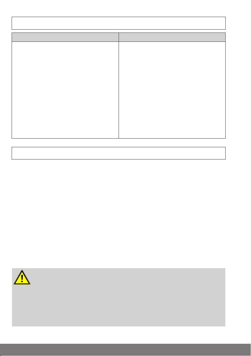
All dimensions in mm.
156
197 32
28,5 118
118
CC51 CC31
Dimensions
9
Page 10
CentralControl CC51
5
1
2
3
6
4
109
8
7
13
12 11
14
15
111213
14
16
17
10987
Device overview
1. Integrated front camera
2. Light sensor
3. Loudspeaker
4. Touchscreen
5. Operating status LED
6. Microphone
7. USB backup memory
8. Free USB connector
9. Centronic stick
10
10. B-Tronic KNX stick
11. Connection for mains adapter
12. Audio output (3.5 mm jack)
13. WLAN stick
14. Network connection (RJ45)
15. Reset button
16. Cover
17. Feet
Page 11
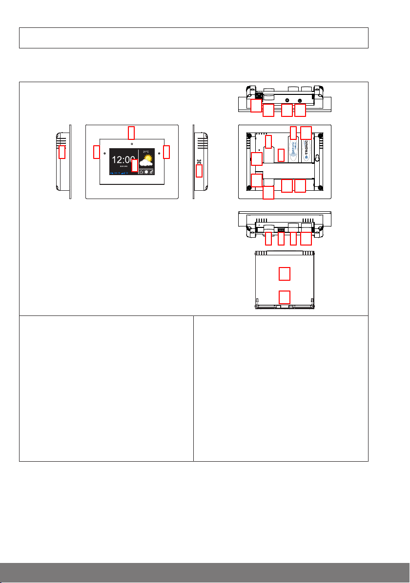
CentralControl CC31
2
1
3
4
5
7 6
8
9
10
11
MAC-ETH: b4:4a:bc:03:09:aa
Serial: 256854214587
4035 645 019 0
B-Tronic CentralControl CC31
4035 200 019 0
SSID: CC31-XXXX
: WPACC31-YYY
IP: 192.168.31.1
IP20
1
2
Connections/slots
1. Mains connection
2. LAN connection
3. HDMI connection
4. AV connection
5. YUV connection
7. USB connection for B-Tronic KNX stick
8. USB connection for Centronic stick
9. USB connection for keypad stick
10. Card slot for SD card
11. Operating status LED
6. Free USB 2.0 connection
Rear of the device
1. WLAN wireless network (SSID) 2. WLAN network key (KEY)
11
Page 12
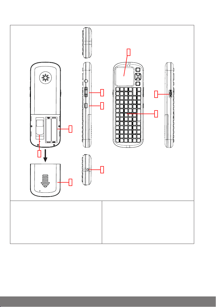
External keypad
1
2
3
4
5
6
7
9
8
1. Touchpad
2. ON/OFF switch
3. Keypad
4. No function
5. Light button
12
6. LED light
7. Battery compartment
8. Compartment for keypad receiver
9. Battery compartment cover
Page 13
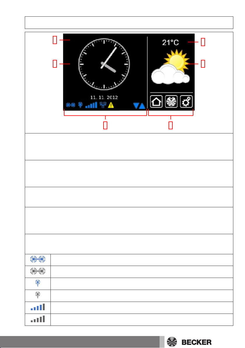
Start / standard screen
1
3
2
4
65
1 Main screen area
The time and date, and in some cases the weather forecast, are displayed on the main
screen area.
2 Navigation and status area
The current weather, status information, and the navigation elements for the programmed receivers are shown in the navigation and status area.
3 Time / date
Display of date and time. The time can be displayed in digital or analogue format.
4 Weather
Display of the current weather at the selected weather location. Displaying the
weather data requires an Internet connection.
5 Device status bar
The statuses of various device-specific functions are displayed on this status bar:
B-Tronic KNX stick is available in the device.
B-Tronic KNX stick is not available in the device.
Centronic RF stick is available in the device.
Centronic RF stick is not available in the device.
WLAN signal strength
No WLAN available
13
Page 14
Network via cable
No network via cable
Access point available
Fault indication
An update is available
The display of blue triangles indicates that more content is available in the
main screen area by scrolling up or down.
6 Main navigation
The main navigation is visible, with an identical format, on all the screens. It consists
of the following three navigation panes:
Clicking this button will always take you back to the start screen.
Clicking this button takes you to the operating facilities for the receivers,
rooms, groups and scenarios.
Clicking this button will take you to the settings.
Mains connection
1. If necessary, pull the cover off the control unit.
2. First connect the mains adapter to the control unit, then plug it into the socket.
3. If you removed the cover, place it back onto the control unit now.
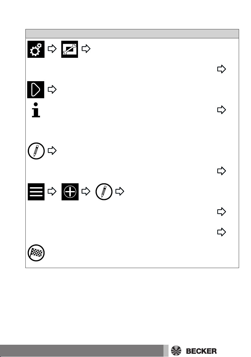
Explanation of pictograms
CAUTION
ATTENTION
14
CAUTION indicates a hazardous situation which, if not
avoided, could result in injury.
ATTENTION indicates measures that must be taken to
avoid damage to property.
Denotes user tips and other useful information.
Page 15
All the symbols in square boxes can be found on the screen and should be
!
operated there using the mouse or touchscreen.
All the symbols in circles provide operating information that should be implemented if a symbol is illustrated in a circle.
Continue with the entries at the point indicated.
Select one or more options from a preset list.*
Fill in one or more text boxes.*
Fill in the text boxes and select the desired options.*
Please note the information on the screen.*
The task is complete.
Perform the next step (with and without identification)
Continue, depending on the result of the previous action
“Action not completed successfully” or “Action completed successfully”
*) It may be necessary to scroll down the page to reach all the information, options, input fields, etc.
15
Page 16
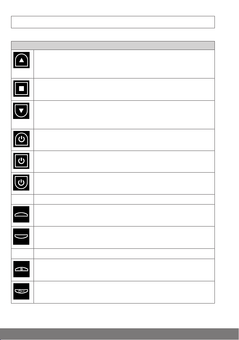
Explanation of the operator controls
1
2
The operator controls may execute different functions depending on the receiver type.
Local interface
Move UP/move IN
Switch on the light and increase the brightness
Manually set the temperature higher
STOP button
Switch off the light
Move DOWN, move OUT
Switch on the light and reduce the brightness
Manually set the temperature lower
ON button
OFF button
ON button
Switch on the anti-freeze mechanism/battery energy-saving mode
Intermediate position 1 (optional)
Saved light value 1 (optional)
Intermediate position 2 (optional)
Saved light value 2 (optional)
Intermediate position with optional closing
Comfort temperature
Eco temperature
16
Page 17
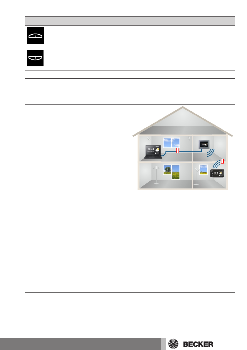
Local interface
a
b
Fold out the foldable roller shutter
Fold up the foldable roller shutter
Operating the house automation with other devices on
the home network
You can use the B-Tronic CentralControl
to “remotely control” home automation
functions using a large number of end
devices that are in your home network.
The devices can be integrated into the
network by means of a network cable a or
WLAN b.
The operating system on which your end
device is based is of no importance. Microsoft Windows (from XP/Internet Explorer 8), Android and Apple iOS (Mac,
iPad, iPhone) are amongst the supported
systems.
To communicate with the central controller over the network, please start your Internet browser and enter the IP number into your browser’s address field.
The entry always starts with “http://” followed by the IP number. This is always represented by four numbers with at most three digits each, separated by dots.
The entry in the example is: http://192.168.0.52/
You can call up the IP number assigned for your central controller by the network on
the “System information” page:
To access your CentralControl quickly at any time, you can save the page you called
up using the IP address as a favourite or store it on your device’s desktop. To ensure
that a different IP address is not used each time the CentralControl is rebooted, it
should be assigned a fixed IP address (see Establishing a network connection).
17
Page 18

Operating the house automation through a device with
mobile Internet access from outside
You need to register with the Becker Gateway Service for easy remote control of
your central controller over the Internet. A
login code is required once in order to set
up gateway access at www.beckercontrol.de.
You will find out how to receive a login
code in the chapter entitled Setting up remote access for a new account or Setting
up remote access for an existing account.
Please note that an Internet connection
and an email account are necessary in order to request a login code. After you
have successfully logged into the Becker
Gateway Service, it is no longer possible
to generate another login code with the
same central controller. You can, of
course, assign a number of central controllers to one user account.
Preparing to commission the CC31
Insert the supplied stick into the B-Tronic CentralControl in accordance with the Device
overview.
There are a number of display options:
• Via television or screen
• Via PC, notebook or tablet
Via television or screen
1. Connect the B-Tronic CentralControl to the television or screen using the HDMI
cable or the AV cable.
2. First connect the mains adapter to the control unit, then plug it into the socket.
Caution
Lay the mains connecting cable in such a way that nobody
can tread on it or trip over it.
18
Page 19
3. The Start / standard screen [}13] appears.
4. You can now input further entries via the internal keypad, or via the external keypad
supplied.
Via PC, notebook or tablet
There are a number of options:
• WLAN
• Ethernet (an Ethernet cable is not included in the scope of supply)
WLAN
The configuration WLAN of the B-Tronic CentralControl
(access point) is used to make the first connection with
your input device.
1. Make a note of the name of the WLAN wireless network (SSID) and of the WLAN
network key (KEY). Both can be found on the back of the B-Tronic CentralControl.
2. Have the wireless networks shown to you by your input device (PC, notebook or
tablet).
3. Select the WLAN wireless network (SSID) that you noted previously from the list of
available connections and start the connection request.
4. Now enter the WLAN network key (KEY) that you noted previously into the field
provided and connect to the B-Tronic CentralControl. Wait until the WLAN connection is established.
5. Then open your browser via the input device.
6. Now type the following address into the browser’s address bar:
http://192.168.31.1/ and confirm it by pressing Enter.
7. The start/standard screen appears.
8. Select
9. Now make the settings for your private network.
10. Then set your input device back to the private network.
If you cannot find your CC31 in your network, you must reset the CC31 to Hot Spot mode. To do so, press the following key combination on the external keypad supplied: ESC
+ Shift + Ctrl. Then repeat the above process.
19
Page 20

Ethernet (an Ethernet cable is not included in the scope of
Language
supply)
1. Connect the B-Tronic CentralControl to your input device (PC, notebook or tablet)
using the Ethernet cable. Wait until the Ethernet connection is established.
Caution
Lay the Ethernet cable in such a way that nobody can tread
on it or trip over it.
2. Then open your browser via the input device.
3. Now type the following address into the browser’s address bar: http://cc31.local/
and confirm it by pressing Enter.
4. The Start / standard screen [}13] appears.
5. Select
6. You can now input further entries via your input device.
Commissioning with the local interface
The following pages will guide you step-by-step through the installation and configuration of the B-Tronic CentralControl. When all the steps described have been carried
out, your rooms and receivers will be configured and you will be able to centrally control
your home.
However, the B-Tronic CentralControl has significantly more convenience and automation options available that you can use to adapt your home automation to suit your individual needs. These functions are described in detail under the menu items from the
chapter entitled Building wiring system settings [}24].
Setting the language
20
Local interface
Page 21

Establishing a network connection
Network settings
Date/time
The full home automation functionality of the B-Tronic CentralControl is naturally available even when it is not connected to a network. However, some additional functions
and access options are only possible with network or Internet access.
To be able to use these functions, please ensure that the B-Tronic CentralControl is
connected to your network, that there is an Internet connection and that the time is set
correctly. The central controller can only be integrated in a network by means of WiFi/
WLAN if the WPA2 encryption is switched on at the router. Please note that this may result in charges depending on your Internet provider’s contractual conditions.
Local interface
To ensure that a different IP address is not used every time the CentralControl reboots, a fixed IP address should be assigned to the CentralControl. The
network configuration must be switched from “Automatic” to “Manual” in this
case. Ask your network administrator for the additional information required
for this purpose.
Setting the time and date
Local interface
21
Page 22

Setting the location
Location
!
This setting affects the weather information used, the time
zone and the Astro function.
Adding a Centronic receiver
Local interface
Local interface
22
Page 23

Adding a B-Tronic receiver
!!!
Adding a room
Local interface
Local interface
Adding elements to a room
End of commissioning
Local interface
23
Page 24

Building wiring system settings
!
!!!
Adding a Centronic receiver
Adding a B-Tronic receiver
Local interface
Local interface
24
Page 25

Deleting a Centronic receiver
!
!
!
!
Local interface
Deleting a B-Tronic receiver
Local interface
25
Page 26
Renaming a receiver
Local interface
The following functions are unavailable on the local interface.
Please make this setting on the web interface.
Adding a Centronic or B-Tronic transmitter
Deleting a Centronic or B-Tronic transmitter
Renaming a transmitter
Adding a Centronic or B-Tronic sensor
Deleting a Centronic or B-Tronic sensor
Renaming a sensor
Adding an internal object
Deleting an internal object
Renaming an internal object
Linking a transmitter to a function (adding logic)
Linking a sensor to a function (adding logic)
Linking an internal object to a function (adding logic)
26
Page 27

Adding a room
Sorting rooms
Deleting a room
My Home settings
Local interface
Local interface
Local interface
Renaming a room
Local interface
27
Page 28

Allocating elements to a room
Local interface
Sorting elements in a room
Local interface
Deleting elements from a room
Local interface
Adding a group
A “group” is a number of receivers combined on one of the transmitter’s channels. All
the receivers in a group respond jointly to signals from the transmitter.
It is important to note that only receivers of the same type – e.g. roller shutter drives or
switching receivers – can be combined in one group.
Local interface
28
Page 29

Local interface
The list of receivers also contains groups and scenarios, and these can also
be assigned to rooms in the exact same way as individual receivers.
Sorting groups
Local interface
Deleting a group
Local interface
Renaming a group
Local interface
Allocating elements to a group
Local interface
29
Page 30

Deleting elements from a group
Local interface
Adding a scenario
Several receivers are combined in one scenario. All the receivers in a scenario respond
jointly to the commands for starting or stopping the scenario. In contrast to the group,
devices combined in one scenario do not have to consist of receivers of the same type.
They can approach positions that have been individually defined beforehand, or can assume switching states.
Confirmation (positive/negative) is only provided once the last scenario participant has
issued a status message.
To ensure correct execution of scenarios that involve several receivers of the same type, (i.e. several roller shutter
drives), please create a shared group for them. This group
can then be applied in the scenario. This measure ensures
that the receivers all receive the travel/switching commands at the same time.
Local interface
The list of receivers also contains groups and scenarios, and these can also
be assigned to rooms in the exact same way as individual receivers.
30
Page 31

Sorting scenarios
Deleting a scenario
Renaming a scenario
Local interface
Local interface
Local interface
Allocating elements to a scenario
Local interface
31
Page 32

Deleting elements from a scenario
Local interface
Adding a camera
It is possible to integrate up to 25 network-enabled cameras that make an MJPEG
stream available. You can find out whether your camera model makes such a stream
available from your camera’s manufacturer. Please note that the central controller can
only display native MJPEG/MJPG streams.
You can find a list of the cameras that Becker has already tested and incorporated at
http://www.becker-antriebe.net/centralcontrol/. You will also find a list of the cameraspecific settings there.
Local interface
Sorting cameras
Deleting a camera
32
Local interface
Local interface
Page 33

Changing camera settings
Adding a radio
Sorting radios
Local interface
Local interface
Local interface
Deleting a radio
Local interface
33
Page 34

Changing radio settings
Automation options
Receiver memory function
Local interface
Automation settings
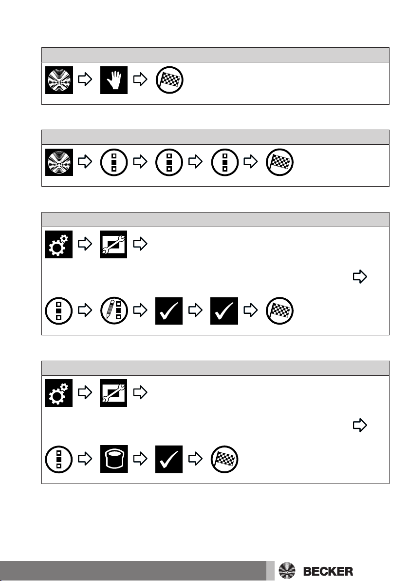
Setting the memory function (ON/OFF)
The CentralControl enables configuration of a number of timer functions. Particularly in
installations where the central controller is installed at a later time, memory functions
that have been set in the drives may already exist.
To completely set all the times through the central controller, the memory times stored
in the drives can be switched off using the “Internal memory function” option.
Please note that the memory function in any given drive is only finally deactivated when
the central controller has once switched it to manual mode (the drive confirms this by
clicking). Switching off in this way occurs at every change to manual mode.
The drives’ memory function can be reactivated at any time using a memory hand-held
transmitter.
34
Local interface
Page 35

Setting the automatic roof window
Automation options
Automatic roof window
Automation options
Holiday function
Local interface
Setting the holiday function
Your CentralControl includes a holiday function, so that even when you are not there,
any possible observer would be given the impression that the drives are not controlled
automatically, but manually. If this function is activated, programmed switching times
are shifted every day by a time determined by a random generator. You can define this
time shift in the “Holiday function” menu. The time that you save is the maximum time
by which the switching time will be moved forwards or backwards.
Local interface
35
Page 36

Setting the sun protection function
Local interface
Adding a timer
To ensure that time commands are executed correctly,
you need to create a shared group for receivers of the
same type. This group can then be applied to the timers.
This measure ensures that the receivers all receive the
travel/switching commands at the same time. All the receivers must be in Automatic mode.
Local interface
You will find a more detailed explanation of the Astro function under Astronomical
function [}53].
Changing a timer
To ensure that time commands are executed correctly,
you need to create a shared group for receivers of the
same type. This group can then be applied to the timers.
This measure ensures that the receivers all receive the
travel/switching commands at the same time. All the receivers must be in Automatic mode.
36
Page 37

Local interface
You will find a more detailed explanation of the Astro function under Astronomical
function [}53].
Deleting a timer
Local interface
Setting the heating functions
Please note that all the heating actuators in a room automatically form a joint climate zone and are controlled together. Individual control is only possible via the “+” and
“–” buttons on the heating actuator.
Local interface
37
Page 38

Access settings
Service
Generate service code
!
Generating a service code
Local interface
38
Page 39
Setting up remote access for an existing account
Remote access
Please take note of the code and complete the registration
process in the web browser using a computer, tablet or mobile
phone. Then enter the following address in the web browser:
www.beckercontrol.de/
Log in
Activate device
No
Local interface
39
Page 40

Setting up remote access for a new account
Please take note of the code and complete the registration
process in the web browser using a computer, tablet or mobile
phone. Then enter the following address in the web browser:
www.beckercontrol.de/
Create new account.
Create account.
Confirm the account. Then enter the following address in the
web browser: www.beckercontrol.de/
Log in.
Remote access
Local interface
40
Page 41

View settings
!
!
Setting the background colour
This function is unavailable on the local interface. Please
make this setting on the web interface.
Setting the visual background effects
This function is unavailable on the local interface. Please
make this setting on the web interface.
Resetting the background colour and the visual background effects to the factory settings
This function is unavailable on the local interface. Please
make this setting on the web interface.
Information settings
System information
Local interface
Reading out the error memory
Local interface
41
Page 42

Reading update news
News
!
Language
Location
Setting the language
Local interface
System settings
Local interface
Setting the location
This setting affects the weather information used, the time
zone and the Astro function.
42
Local interface
Page 43

Setting the time and date
Date/time
Network settings
Local interface
Establishing a network connection
The full home automation functionality of the B-Tronic CentralControl is naturally available even when it is not connected to a network. However, some additional functions
and access options are only possible with network or Internet access.
To be able to use these functions, please ensure that the B-Tronic CentralControl is
connected to your network, that there is an Internet connection and that the time is set
correctly. The central controller can only be integrated in a network by means of WiFi/
WLAN if the WPA2 encryption is switched on at the router. Please note that this may result in charges depending on your Internet provider’s contractual conditions.
Local interface
To ensure that a different IP address is not used every time the CentralControl reboots, a fixed IP address should be assigned to the CentralControl. The
network configuration must be switched from “Automatic” to “Manual” in this
case. Ask your network administrator for the additional information required
for this purpose.
43
Page 44

Update
Update
!
Download and install now
!
Backup + Restore
Carry out backup now
Local interface
Even if you decide not to connect your central controller to the Internet, you are still
able to download current software updates and, in that way, install additional functionalities or bug fixes at a later time. To do so, please download the “CC Updater”
onto your PC by using the following link: https://www.becker-antriebe.de/produktuebersicht/hausautomatisierung-centralcontrol/manuelles-update.html
Then start the “CC Updater” and follow the instructions on the screen.
Creating a backup
44
Local interface
Page 45

Restoring from backup
Backup + Restore
Restore settings
Factory settings
Reboot
Factory reset
All settings will be reset, and all rooms, scenarios, groups,
receivers and so forth will be deleted.
Local interface
Local interface
Reboot
Local interface
45
Page 46

Rooms
Setting receivers to Automatic mode
The B-Tronic CentralControl enables you to control receivers, groups or scenarios according to time.
All the control tasks carried out by the CentralControl based on programmed specifications (such as switching times) are referred to as “Automatic functions”.
Automatic functions can be activated or deactivated for either one single receiver or for
several receivers (the entire home or one room) at the same time. Receivers for which
no automatic options have been defined remain unaffected by this change.
Local interface
Setting all the receivers in the room to Automatic mode
Local interface
Setting all the receivers in the home to Automatic mode
Local interface
Setting receivers to Manual mode
Local interface
Setting all the receivers in the room to Manual mode
Local interface
46
Page 47
Setting all the receivers in the home to Manual mode
Favourites
Favourites
Local interface
Operating receivers
Local interface
Adding favourites
Local interface
Deleting favourites
Local interface
47
Page 48

Operating groups
Operating scenarios
Calling up cameras
Groups
Local interface
Scenarios
Local interface
Cameras
Local interface
Starting a radio
48
Radios
Local interface
Page 49

Stopping a radio
Local interface
Weather forecast
Local interface
Changing the batteries of an external keyboard
Dispose of exhausted batteries properly. Only replace
batteries with ones of the identical type (LR03; AAA).
1. Open the cover of the battery compartment.
2. Take out the batteries.
3. Insert the new batteries correctly.
4. Close the cover of the battery compartment.
Cleaning
Only clean the device with a suitable cloth. Do not use aggressive cleaning agents that
may damage the surface.
49
Page 50

Technical data
Technical data for the CC51
Supply voltage 230 V/50 Hz
Degree of protection IP 20
Permissible ambient temperature and air humidity
Maximum emitted transmission output ≤ 25 mW
Radio frequency 868.3 MHz
CPU ARM9 454 MHz
Memory 128 MB
Display 10.9 cm/4.3 inch touchscreen
Camera 640 x 480 pixels, VGA RGB
Operating system Linux
Dimensions (W x H x D) 197 x 156 x 34 mm
0°C to +55°C at a relative humidity
of between 20% and 80% (noncondensing)
Resolution: 480 x 272 pixels
Connections
USB WLAN stick IEEE802.11n
WPA/WPA2
Flash memory USB stick
USB Centronic RF stick 868.3 MHz
USB B-Tronic KNX stick 868.3 MHz
Ethernet 10/100 Mbit, standard RJ45
Audio output 3.5 mm jack
The maximum transmitter range on and in the building is up to 25m, and up to 350m in
the open.
50
Page 51

Technical data for the CC31
Supply voltage 230 V/50 Hz
Degree of protection IP 20
Permissible ambient temperature and air humidity
Maximum emitted transmission output ≤ 25 mW
Radio frequency 868.3 MHz/2.4 GHz
CPU ARM9 454 MHz
Memory 128 MB
Operating system Linux
Dimensions (W x H x D) 118 x 118 x 28.5 mm
0°C to +40°C at a relative humidity
of between 20% and 80% (noncondensing)
Connections
Integrated WLAN IEEE802.11n
WPA/WPA2
Flash memory SD card
USB Centronic RF stick 868.3 MHz
USB KNX stick 868.3 MHz
Ethernet 10/100 Mbit, standard RJ45
HDMI
Audio output 3.5 mm jack
The maximum transmitter range on and in the building is up to 25m, and up to 350m in
the open.
51
Page 52

What to do if...?
Problem Remedy
B-Tronic CentralControl is not working/
does not start.
Weather is not displayed. Connect the B-Tronic CentralControl to
Radio does not work. Connect the B-Tronic CentralControl to
Time and date are not set automatically. Change the automatic time check from
Programming a receiver does not work. Reduce distance from receiver.
Check the mains connection (see Device
overview).
the network and Internet (see Establishing
a network connection [}43]).
the network and Internet (see Establishing
a network connection [}43]).
Increase the volume. (see Starting a radio
[}48]).
Internet speed is insufficient.
Manual to Automatic (see Setting the time
and date [}43]).
Connect the B-Tronic CentralControl to
the network and Internet (see Establishing
a network connection [}43]).
52
Deactivate all repeaters.
Reprogram the receiver according to the
receiver’s instructions.
Select the correct receiver type (KNX/
CENTRONIC) (see Adding a Centronic receiver [}24] or Adding a B-Tronic receiver [}24]).
Select the correct device type (tubular
drive/switching actuator/dimming actuator, etc.) (see Adding a Centronic receiver [}24] or Adding a B-Tronic receiver [}24]).
Make free storage space available according to the receiver’s instructions.
Page 53

Problem Remedy
Switching/movement of a receiver does
not work.
You will find further information at http://www.becker-antriebe.net/centralcontrol/.
Check the receiver’s mains connection.
Reprogram the receiver.
Reduce the distance from the receiver, or
use a repeater.
Reduce the number of repeaters if using
several of them.
Simplified EU declaration of conformity
Becker-Antriebe GmbH hereby declares that this radio control system complies with
Directive 2014/53/EU.
The full text of the EU declaration of conformity is available at the following web address:
www.becker-antriebe.com/ce
Subject to technical changes without notice.
Annex
Astronomical function
To execute Astro functions the location of the CentralControl must be entered correctly. This can be specified in the
Select location menu.
The B-Tronic CentralControl controls your home automation systems as required via
the Astro function, according to the calculated sunrise and sunset times.
You can assign one of the two Astro versions to each timer:
- Astro dawn - depending on sunrise
- Astro evening - depending on sunset
For each of these two variants there are two more possible settings, described in more
detail below.
Diagram notes:
- Each of the yellow lines represents the time of sunrise or sunset.
- Each of the blue lines represents the time at which the desired action is to be performed by the timer.
53
Page 54

ASTRO DAWN
Winter time Summer time Winter time
Jan. Feb. Mar.
Apr. May June July Aug.
Sep.
Oct. Nov. Dec.
Winter time Summer time Winter time
Jan. Feb. Mar.
Apr. May June July Aug.
Sep.
Oct. Nov. Dec.
Blocking time
Winter time Summer time Winter time
Jan. Feb. Mar.
Apr. May June July Aug.
Sep.
Oct. Nov. Dec.
Winter time Summer time Winter time
Jan. Feb. Mar.
Apr. May June July Aug.
Sep.
Oct. Nov. Dec.
Winter time Summer time Winter time
Jan. Feb. Mar.
Apr. May June July Aug.
Sep.
Oct. Nov. Dec.
Blocking time
Astro dawn without any additional settings:
The desired action is performed at the
time of sunrise.
Astro dawn with blocking time:
The desired action is carried out at the
time of sunrise, but not before the set
blocking time (which is 6:00 AM in the example).
Astro dawn with shift:
The desired action is not carried out at
dawn itself, but is shifted by whatever "Astro shift" has been set.
In the example, 1 hour has been set as the
Astro shift.
The action is not, for example, carried out
at 7:00 AM (sunrise), but an hour later at
8:00 AM.
ASTRO EVENING
Astro evening without any additional
settings:
The desired action is performed at the
time of sunset.
Astro evening with blocking time:
The desired action is carried out at the
time of sunset, but not after the set blocking time (which is 6:00 PM in the example).
54
Page 55

Astro evening with shift:
Winter time Summer time Winter time
Jan. Feb. Mar.
Apr. May June July Aug.
Sep.
Oct. Nov. Dec.
The desired action is not carried out at
evening itself, but is shifted by whatever
"Astro shift" has been set.
In the example, 1 hour has been set as the
Astro shift.
The action is not, for example, carried out
at 7:00 PM (sunset), but an hour earlier at
6:00 PM.
55
Page 56

 Loading...