

Page 1

CentralControl
CC31
en
Commissioning instructions
Central Controller
Important information for:
• Fitters / • Electricians / • Users
Please forward accordingly!
These instructions must be kept safe for future reference.
4035 630 087 0a21/07/2017
Becker-Antriebe GmbH
Friedrich-Ebert-Straße 2-4
35764 Sinn/Germany
www.becker-antriebe.com
Page 2

Table of contents
General ................................................................................................................ 3
Warranty .............................................................................................................. 3
Items included ...................................................................................................... 4
Safety instructions ................................................................................................ 4
Intended use ........................................................................................................ 5
Dimensions .......................................................................................................... 6
Device overview .................................................................................................... 6
Online documentation ........................................................................................... 8
Preparation for Commissioning .............................................................................. 9
Start / standard screen.........................................................................................11
Commissioning, step-by-step ...............................................................................12
Selecting a language...................................................................................... 13
Network settings............................................................................................ 14
Date / time .................................................................................................... 16
Select weather location .................................................................................. 18
Programming receivers .................................................................................. 20
Creating rooms.............................................................................................. 23
Add receivers to rooms................................................................................... 25
Creating groups............................................................................................. 27
Program receivers for groups.......................................................................... 29
Operation............................................................................................................32
Operating receivers........................................................................................ 32
Tubular drive receivers .............................................................................. 32
Dimmer receiver ....................................................................................... 33
Switch receivers........................................................................................ 34
Operating groups........................................................................................... 34
Additional configuration and operation options .......................................................35
Changing batteries...............................................................................................36
Cleaning..............................................................................................................36
Technical data .....................................................................................................37
Simplified EU declaration of conformity..................................................................38
2
Page 3
General
With the B-Tronic CentralControl you can operate the drives and control units with bidirectional KNX radio and the Centronic I and II range of controls.
This device uses free/open source software. The source code can be downloaded from
http://www.b-tronic.net/source/. On request, Becker Antriebe will make the source
code available on a CD-ROM at cost price. Please contact source@b-tronic.net if you
are interested.
As a result of continuous further development of the software, there can be differences
between the illustrations and your device.
This is not, however, important for any of the procedures described.
Please observe these Assembly and Operating Instructions when installing and setting
up the equipment.
Explanation of pictograms
CAUTION
ATTENTION
CAUTION indicates a hazardous situation
which, if not avoided, could result in injury.
ATTENTION indicates measures that must be
taken to avoid damage to property.
Denotes user tips and other useful information.
Warranty
Structural modifications and incorrect installation which are not in accordance with
these and our other instructions can result in serious injuries, e.g., crushing of limbs.
Therefore, structural modifications may only be carried out with our prior approval and
strictly in accordance with our instructions, particularly the information contained in
these Assembly and Operating Instructions.
Any further processing of the products which does not comply with their intended use is
not permitted.
The end product manufacturer and fitter have to ensure that all the relevant current
statutory, official and, in particular, EMC regulations are adhered to during utilisation of
our products, especially with regard to end product manufacture, installation and customer advice.
3
Page 4
Items included
• B-Tronic CentralControl controller
• USB WLAN stick
• USB Flash memory stick
• USB Centronic stick
• USB B-Tronic/KNX stick (optional)
• Mains adapter
• Radio keypad
• Commissioning instructions
Safety instructions
General information
• Please keep the instructions safe!
• Only use in dry rooms.
• Keep people out of the system’s range of travel.
• Keep children away from control units.
• Observe all pertinent country-specific regulations.
• Do not place any objects on the control unit.
• Clean the control unit with a soft, dry, lint-free cloth, and do not use any chemical
cleaning agents.
Caution
• If the system is controlled by one or more transmitters, the system’s
range of travel must always be visible during operation.
• Keep packaging materials such as film away from children. Misuse
can create the risk of suffocation.
• Switch the control unit off immediately if the mains adapter and the
plug to which it is connected is burnt or damaged. If a mains adapter
is damaged, replace it with an original one. A faulty mains adapter
must not under any circumstances be repaired.
• Switch the control unit off immediately if the housing of the control
unit is damaged, or if liquids have penetrated.
4
Page 5
Attention
• Do not let any objects fall onto the control unit.
• If a display is present, protect it against being scratched by hard ob-
jects (e.g. rings, fingernails, wristwatches)
• Wait until the control unit has adjusted to ambient temperature be-
fore connecting the control unit to the mains adapter. Condensation
that could lead to a short circuit can be caused inside the control unit
by large differences in temperature and air humidity.
Intended use
The B-Tronic CentralControl may only be used for the operation of suitable drives and
control units with bidirectional KNX radio and with the Centronic I and II range of controls. You can operate a group, or multiple groups, of devices with this controller.
• Please note that radio-controlled systems may not be used in areas with a high risk
of interference (e.g. hospitals, airports).
• The remote control is intended solely for use with equipment and systems in which
malfunctions in the transmitter or receiver would not pose any risk to persons, animals or property, or which contain safety devices to eliminate such risks.
• The operator is not protected from interference from other telecommunications
systems and terminal equipment (e.g. even from radio-controlled systems which
are properly operated in the same frequency range).
• Only connect radio receivers to devices and systems approved by the manufac-
turer.
• Ensure that the control unit is not installed or operated close to metal
surfaces or magnetic fields.
• Radio-controlled systems transmitting on the same frequency may
cause reception interference.
• Note that the range of the radio signal is limited by legislation as well
as by design.
5
Page 6
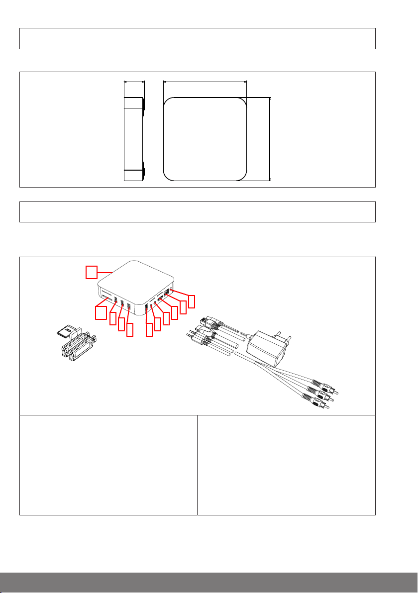
All dimensions in mm.
28,5 118
118
2
1
3
4
5
7 6
8
9
10
11
Connections / slots
Dimensions
Device overview
1. Mains connection
2. LAN connection
3. HDMI connection
4. AV connection
5. YUV connection
6. Free USB 2.0 connection
6
7. USB connection for KNX stick
8. USB connection for Centronic stick
9. USB connection for keypad stick
10. Card slot for SD card
11. Operating status LED
Page 7
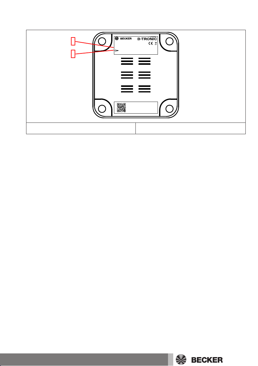
Rear of the device
MAC-ETH: b4:4a:bc:03:09:aa
Serial: 256854214587
4035 645 019 0
B-Tronic CentralControl CC31
4035 200 019 0
SSID: CC31-XXXX
: WPACC31-YYY
IP: 192.168.31.1
IP20
1
2
1. WLAN wireless network (SSID) 2. WLAN network key (KEY)
7
Page 8
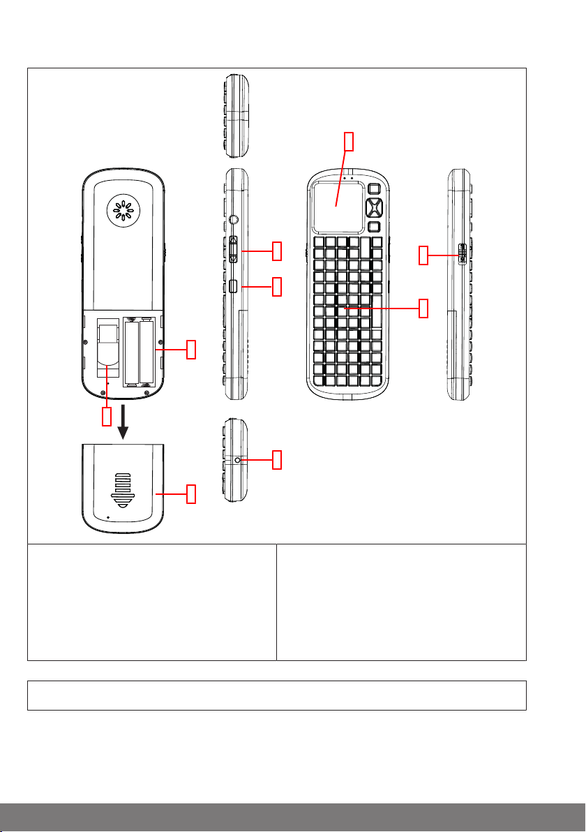
External keypad
1
2
3
4
5
6
7
9
8
1. Touchpad
2. ON / OFF switch
3. Keypad
4. No function
5. Light button
6. LED light
7. Battery compartment
8. Compartment for keypad receiver
9. Battery compartment cover
Online documentation
In addition to the present commissioning instructions, we make comprehensive documentation available to you online.
Please visit the following Internet site:
http://www.becker-antriebe.net/centralcontrol/.
8
Page 9

Preparation for Commissioning
Insert the supplied stick into the B-Tronic CentralControl in accordance with the Device
overview [}6].
There are a number of display options:
• Via television or screen
• Via PC, notebook or tablet
Via television or screen
1. Connect the B-Tronic CentralControl with the HDMI cable or the AV cable to the
television or screen.
2. First connect the mains adapter to the control unit, then plug it into the socket.
Caution
Lay the mains connecting cable in such a way that nobody can tread on
it or trip over it.
3. The Start / standard screen [}11] appears.
4. You can now input further entries via the internal keypad, or via the external keypad
supplied.
Via PC, notebook or tablet
There are a number of options:
• WLAN
• Ethernet (an Ethernet cable is not included in the scope of supply)
WLAN
The configuration WLAN of the B-Tronic CentralControl (access point)
is used to make the first connection with your input device.
1. Take a note of the name of the WLAN wireless network (SSID) and of the WLAN network key (KEY). Both can be found on the back of the B-Tronic CentralControl.
2. Have the wireless networks shown to by your input device (PC, notebook or tablet).
3. Select the WLAN wireless network (SSID) that you noted previously from the list of
available connections, and start the connection request.
4. Now enter the WLAN network key (KEY) that you noted earlier into the field
provided, and connect to the B-Tronic CentralControl. Wait until the WLAN connection is established.
9
Page 10
5. Now open your browser via the input device.
6. Type the following address into the browser's address bar: http://192.168.31.1/
and confirm it by pressing Enter.
7. Now click on the cogwheel in the top right-hand corner with the arrow.
8. Select the VNC interface.
9. The Start / standard screen [}11] appears.
10. Now make the settings for your private network, as described under Network settings [}14].
11. Then set your input device back to the private network.
Ethernet (an Ethernet cable is not included in the scope of
supply)
1. Connect the B-Tronic CentralControl via the Ethernet cable to your input device
(PC, notebook or tablet). Wait until the Ethernet connection is established.
Caution
Lay the Ethernet cable in such a way that nobody can tread on it or trip
over it.
2. Now open your browser via the input device.
3. Type the following address into the browser's address bar: http://cc31.local/ and
confirm it by pressing Enter.
4. Now click on the cogwheel in the top right-hand corner with the arrow.
5. Select the VNC interface.
6. The Start / standard screen [}11] appears.
7. You can now input further entries through your input device.
10
Page 11
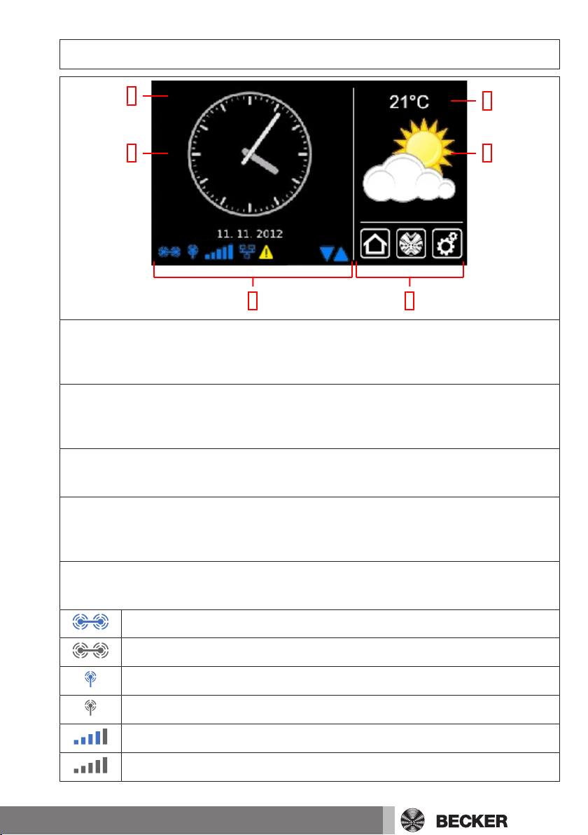
Start / standard screen
1
3
2
4
65
1 Main screen area
The time and date, and in some cases the weather forecast, are displayed on the main
screen area.
2 Navigation and status area
The current weather, status information, and the navigation elements for the programmed receivers are shown in the navigation and status area.
3 Time / date
Display of date and time. The time can be displayed in digital or analogue format.
4 Weather
Display of the current weather at the selected weather location. Displaying the
weather data requires an Internet connection.
5 Device status bar
The statuses of various device-specific functions are displayed on this status bar:
B-Tronic KNX stick is available in the device.
B-Tronic KNX stick is not available in the device.
Centronic RF stick is available in the device.
Centronic RF stick is not available in the device.
WLAN signal strength
No WLAN available
11
Page 12
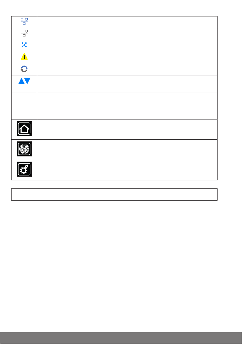
Network via cable
No network via cable
Access point available
Fault indication
An update is available
The display of blue triangles indicates that more content is available in the
main screen area by scrolling up or down.
6 Main navigation
The main navigation is visible, with an identical format, on all the screens. It consists
of the following three navigation panes:
Clicking this button will always take you back to the start screen.
Clicking this button takes you to the operating facilities for the receivers,
rooms, groups and scenarios.
Clicking this button will take you to the settings.
Commissioning, step-by-step
• Selecting a language [}13]
• Network settings [}14]
• Date / time [}16]
• Select weather location [}18]
• Programming receivers [}20]
• Creating rooms [}23]
• Add receivers to rooms [}25]
• Creating groups [}27]
• Program receivers for groups [}29]
12
Page 13

Selecting a language
1
Radio
Cameras
House installation
Settings
Configuration
Select an
application
2
System information
Select weather location
Date / time
Network settings
Configuration
Selecting a language
Please select the
desired menu item
3
Screen settings
Language
Deutsch
Please select
your
language
English
Francais
Nederlands
4
5
Italiano
1 Please press the "Programs and settings" button.
2 On the "Programs and settings" screen
you should now select the "Configuration"
menu item.
3 Now select "Selecting a language" in
the configuration menu.
4 Choose the language you want in the
language menu.
5 You confirm your input and close the
menu with the green tick.
13
Page 14

Network settings
1
Radio
Cameras
House installation
Settings
Configuration
Select an
application
2
System information
Select weather location
Date / time
Network settings
Configuration
Selecting a language
Please select the
desired menu item
3
Screen settings
The full home automation functionality of the B-Tronic CentralControl is available even
when it is not connected to a network. However, some additional functions and access
options are only possible with network or Internet access.
In order to be able to use these functions, make sure that the B-Tronic CentralControl is
connected to your network, that there is an Internet connection, and that the time is set
correctly. Do remember that this may result in charges, depending on the contractual
conditions of your Internet supplier.
1 Please press the "Programs and settings" button.
2 On the "Programs and settings" screen
you should now select the "Configuration"
menu item.
3 Now select "Network settings" in the
configuration menu.
14
Page 15

4 You can change the name of the B-
Network
Network
configuration
Ethernet
Interface
5
WiFi
WiFi access data
SSID / network name
6
Host name
4
beckernet
CentralControl
Activate access point
Network
Manual input
Select
network
Tronic CentralControl here.
5 Selection for access point (configuration WLAN of the B-Tronic CentralControl.
Only available on the CC31) Ethernet
(wired network installation) or WiFi
(WLAN / radio network installation).
6 SSID = network identifier
(this is only needed for WiFi / WLAN connections)
You will only be able to select the networks flagged with a green symbol.
15
Page 16

7 Key = password
Network configuration
Key / password (PSK)
Automatic (DHCP)
Manual
IP address
Net mask
Gateway
Name server
7
8
9
10
11
12
14
WLAN driver version
Modification requires restart
Standard
Alternative
13
1
(this is only needed for WiFi / WLAN connections)
Please note that the central control can
only be linked into a network by means of
WiFi / WLAN if the WPA2 encryption is
switched on at the router.
An automatic DHCP is usually activated in
private networks. If this is not the case,
please ask your network administrator for
the entries required for the fields 9, 10,
11 and 12.
To ensure that a different IP address
is not used every time the CentralControl reboots, a fixed IP address should
be assigned to the CentralControl.
(Select 8 = Manual, and input the information needed for the fields 9, 10,
11 and 12).
After configuration has been finished,
some of the data can also be seen under
"System information".
13 If you are unable to establish a connection to your WLAN network using the
standard WLAN driver you should test the
alternative WLAN driver. Only available on
the CC51.
14 You confirm your input and close the
menu with the green tick.
Date / time
1 Please press the "Programs and set-
tings" button.
16
Page 17

2 On the "Programs and settings" screen
Radio
Cameras
House installation
Settings
Configuration
Select an
application
2
System information
Select weather location
Date / time
Network settings
Configuration
Selecting a language
Please select the
desired menu item
3
Screen settings
Date / time
Settings
4
automatic (NTP)
Time
5
6
7
Time
manual
Date
Time format
Date format
Time zone
Berlin
8
9
10
you should now select the "Configuration"
menu item.
3 Now select "Date / time" in the configuration menu.
4 Now please choose whether you want
the time to be obtained automatically from
the Internet, or whether you want to set it
manually.
The central controller needs an Internet
connection if it is to obtain the time and
date information automatically.
5 Setting the time manually.
This menu item is omitted if "Automatic" is
selected under Point 4.
6 Setting the date manually.
This menu item is omitted if "Automatic" is
selected under Point 4.
7 Setting the format in which the time will
be displayed.
8 Setting the format in which the date will
be displayed.
9 Setting the time zone.
10 You confirm your input and close the
menu with the green tick.
17
Page 18

Select weather location
1
Radio
Cameras
House installation
Settings
Configuration
Select an
application
2
System information
Select weather location
Date / time
Network settings
Configuration
Selecting a language
Please select the
desired menu item
3
Screen settings
Displaying the weather data requires an Internet connection.
In order to be able to display the correct weather data on your B-Tronic CentralControl
it is necessary to provide the location for which the weather data is to be displayed.
If the place you want is not available in the selection list, choose the nearest larger city.
1 Please press the "Programs and settings" button.
2 On the "Programs and settings" screen
you should now select the "Configuration"
menu item.
3 Now select "Select weather location" in
the configuration menu.
18
Page 19

4 The location that is currently set for the
Weather
Location:
Location for weather
information
4
Sinn, Germany
5
Set using location data
Options
Search locations
Paris
Please enter your location
6
7
Locations found
Select your
location
8
9
Weather
Location:
Location for weather
information
Paris
Set using location data
Options
11
10
weather data is shown on the display.
5 To change the location, click the field
where the name is displayed.
6 Now enter the location that you want.
Please make sure that you don't use any
special national characters.
For example:
- München should be written Muenchen
- Orléans should be written Orleans
7 Confirm your input by clicking the green
tick.
8 If your entry results in more than one hit,
a selection list of possible locations will be
displayed.
Select the location you want.
To execute Astro functions the location of the CentralControl must be
entered correctly. This can be specified in the Select location menu.
9 You confirm your input and close the
menu with the green tick.
10 Alternatively, you can also choose your
current location as the weather location.
To do this, simply click the "Set using location data" button.
11 Confirm your input by clicking the
green tick.
19
Page 20

12 After the central controller has entered
Select weather location
Date / time
Network settings
Configuration
Please select the
desired menu item
12
Location
1
Radio
Cameras
House installation
Settings
Configuration
Select an
application
2
System information
Rooms
Scenarios
Groups
Setup
Receiver
Please select
a function
3
Timers
the weather location according to your
specifications, the screen returns automatically to the previous menu.
Programming receivers
1 Please press the "Programs and set-
tings" button.
2 On the "Programs and settings" screen
you should now select the "House installation" menu item.
3 On the "House installation" screen you
should now select the "Receivers" menu
item.
20
Page 21

4 Select the [ + ] button in order to add a
Receiver
installation
Add / select
receiver
4
Drive Centronic
Dimmer KNX
Socket switch KNX
Switch KNX
Receiver name:
Receiver type:
Device type:
Tubular drive / ext.
Switching actuator
Add
receiver
Configure
settings
Dimming actuator
Centronic
B-Tronic / KNX-RF
5
Awning
Blind
Screen
Shade sail
Awning heater
Door
Door (impulse)
Heating actuator
New
receiver
Please enter
a name
7
Receiver
6
receiver.
A name is first assigned to a new receiver.
Do please make sure that you name the
receivers in a meaningful way, so that
when they have all been added they can
be distributed around the rooms according to their names.
5 Tap the name field.
6 The keyboard opens. Enter the name of
the new receiver here.
The name "Receiver" has been used in
the example.
7 You confirm your input and close the
keyboard with the green tick.
21
Page 22

8 Selecting the receiver type.
8
9
Receiver
10
Receiver name:
Receiver type:
Device type:
Tubular drive / ext.
Switching actuator
Add
receiver
Configure
settings
Dimming actuator
Centronic
B-Tronic / KNX-RF
Awning
Blind
Screen
Shade sail
Awning heater
Door
Door (impulse)
Heating actuator
Put the receiver into
programming mode now!
Programming mode
active?
Add
receiver
11
12
Two options are available:
- B-Tronic / KNX (bidirectional - with confirmation function)
- Centronic (unidirectional - without confirmation function)
Only certain device types are available for
selection, depending on the selected receiver type.
9 Selecting the device type.
Several options are available:
For device types "Door" and "Door (impulse)", please note the following:
Depending on the functions available on
the door drive being programmed, "Door"
must be selected for door control units
with defined UP/STOP/DOWN commands
and Door (impulse) for door control units
with impulse sequences (UP/STOP/
DOWN/STOP etc.).
10 You confirm your input and move on to
the next screen with the green tick.
11 The receiver must now be made ready
for programming.
B-Tronic / KNX devices:
Please find the procedure for the receiver
in the operating instructions for the device
that is to be programmed.
Centronic devices:
A Centronic receiver can only be programmed when it is put into programming
mode by its master transmitter. Here
again you can find the exact procedure in
the operating instructions for the particular receiver.
12 You confirm your input and move on to
the next screen with the green tick.
22
Page 23

13 In addition to the information on the
The receiver has been
successfully programmed
and can now be added
to groups or rooms.
Program
13
14
B-Tronic / KNX-RF
Testen
B-Tronic / KNX-RF
A
15
B
C
Receiver
installation
Add / select
receiver
16
Receiver
Drive Centronic
Switch KNX
Dimmer KNX
1
screen saying that the programming has
been completed successfully, many receivers also confirm correct programming. This is often done by "clicking" at
motors, or by flashing the status LED at
the receiver. The manual for the receiver
concerned will tell you whether the receiver you are programming provides
confirmation, and if so, how.
14 You confirm your input and close the
menu with the green tick.
You can now test the drive by operating it
with the following buttons.
A UP button
B STOP button
C DOWN button
15 You close the test menu with the green
tick.
16 The new receiver can now be seen in
the receiver selection menu.
Creating rooms
1 Please press the "Programs and set-
tings" button.
23
Page 24

2 On the "Programs and settings" screen
Radio
Cameras
House installation
Settings
Configuration
Select an
application
2
System information
Rooms
Scenarios
Groups
Setup
Receiver
Please select
a function
3
Timers
Rooms
Add / select
room
Living room
4
New room
Please enter
a name
5
you should now select the "House installation" menu item.
3 On the "House installation" screen you
should now select the "Rooms" menu
item.
4 Select the [ + ] button in order to add a
room.
5 Tap the name field.
24
Page 25

6 The keyboard opens. Enter the name of
New room
Please enter
a name
6
Bedroom
7
Rooms
Add / select
room
Living room
8
Bedroom
1
Radio
Cameras
House installation
Settings
Configuration
Select an
application
2
System information
the new room here.
The name "Bedroom" has been used in
the example.
7 You confirm your input and close the
keyboard with the green tick.
8 The new room can now be seen in the
room selection menu.
Add receivers to rooms
1 Please press the "Programs and set-
tings" button.
2 On the "Programs and settings" screen
you should now select the "House installation" menu item.
25
Page 26

3 On the "House installation" screen you
Rooms
Scenarios
Groups
Setup
Receiver
Please select
a function
3
Timers
Rooms
Add / select
room
Living room
4
Bedroom
Bedroom
Add / select
receiver
or edit room
5
6
Add
receiver
Choose a
receiver to add
Switch
Drives
Drive Centronic
Dimmer KNX
7
should now select the "Rooms" menu
item.
4 Choose the room in which you want to
add receivers.
For example: Bedroom
5 No receiver has yet been assigned to
the chosen room (Bedroom) in the example. For this reason, the list of receivers contained in the room is still empty.
6 Select the [ + ] button in order to add a
receiver to the chosen room.
7 The list that is now shown displays all
the available receivers, i.e. those that
have not yet been assigned to a room.
You add this receiver to the room by tapping it.
The list of receivers also contains
groups and scenarios, and these can
also be assigned to rooms in just the
same way as individual receivers.
26
Page 27

8 The chosen receiver (switch) has now
Bedroom
Add / select
receiver
or edit room
Switch
8
1
Radio
Cameras
House installation
Settings
Configuration
Select an
application
2
System information
been assigned to the room (Bedroom),
and appears in the list of receivers contained in the room.
Creating groups
A "group" is a number of receivers combined on one channel of the transmitter. All receivers in a group respond jointly to signals from the transmitter.
It is important to bear in mind that only receivers of the same type – e.g. roller shutter
drives or switching receivers for example – can be combined in one group.
A 1-channel hand-held transmitter can also control groups, although only one group
per hand-held transmitter.
With bidirectional devices, confirmation (positive/negative) is only provided once the
last participant in the group has issued a status message.
1 Please press the "Programs and settings" button.
2 On the "Programs and settings" screen
you should now select the "House installation" menu item.
27
Page 28

3 On the "House installation" screen you
Rooms
Scenarios
Groups
Setup
Receiver
Please select
a function
3
Timers
Switch
4
Drives
Group
setup
Add / select
group
Tubular drive / ext.
6
Add
group
Adjust
settings
Switching actuator
Dimming actuator
5
Name
new group
7
New group
Please enter
a name
8
should now select the "Groups" menu
item.
4 Select the [ + ] button in order to add a
group.
5 Groups can only consist of receivers of
the same type.
Please choose the desired receiver type
for the group that is to be created.
6 Tap the name field.
7 The keyboard opens. Enter the name of
the new group here.
The name "New group" has been used in
the example.
8 You confirm the name you have entered
and close the keyboard with the green
tick.
28
Page 29

9 You confirm your entries about the new
Tubular drive / ext.
Add
group
Adjust
settings
Switching actuator
Dimming actuator
9
Name
new group
Group
setup
Add / select
group
new group
Switch
Drives
10
1
Radio
Cameras
House installation
Settings
Configuration
Select an
application
2
System information
group and close the menu with the green
tick.
10 The new group is now visible in the list
of all groups.
The list of receivers also contains
groups and scenarios, and these can
also be assigned to rooms in just the
same way as individual receivers.
Program receivers for groups
1 Please press the "Programs and set-
tings" button.
2 On the "Programs and settings" screen
you should now select the "House installation" menu item.
29
Page 30

3 On the "House installation" screen you
Rooms
Scenarios
Groups
Setup
Receiver
Please select
a function
3
Timers
Group
setup
Add / select
group
new group
Switch
Drives
4
New group
Add / select
receiver
5
6
Add
receiver
Choose a receiver
to add
Drives
Drive Centronic
Drive B-Tronic
7
should now select the "Groups" menu
item.
4 Select the group to which you want to
assign receivers.
For example: "New group"
5 No receivers have yet been assigned to
the chosen group (New group) in the example. For this reason, the list of receivers contained in the group is still empty.
6 Select the [ + ] button in order to add a
receiver to the group.
7 All the receivers are visible in the list that
is now displayed.
You add this receiver to the group by tapping it.
30
Page 31

8 The chosen receiver (B-Tronic drive)
New group
Add / select
receiver
Drive B-Tronic
8
has now been assigned to the group (New
group), and appears in the list of receivers
contained in the group.
31
Page 32

Operation
11
22
121
2
11
22
Operating receivers
1. Press the button in order to open the "My house" menu.
2. Now select the room you want.
3. Then choose the receiver that is to be operated.
4. You can now operate the receiver.
5. Press the " " button when you want to close the menu.
Tubular drive receivers
With B-Tronic receivers you get feedback on the current status and
have the option of tapping the desired position on the status display in
order to initiate a corresponding drive command.
UP button
STOP button
DOWN button
Intermediate position 1
Intermediate position 2
Status display
32
Page 33

Dimmer receiver
121
2
121
2
11
22
With B-Tronic receivers you get feedback on the current status and
have the option of tapping the desired position on the status display in
order to initiate a corresponding dimming command.
UP button
STOP button
DOWN button
Intermediate position 1
Intermediate position 2
Status display
33
Page 34

Switch receivers
With B-Tronic receivers you get feedback on the current status.
Operating groups
ON button
OFF button
Status display
Groups can only consist of receivers of the same type.
Just like receivers, groups can be assigned to rooms.
1. Press the button in order to open the "My house" menu.
2. Then press the "Groups" button.
3. Then select the group that you want.
4. You can now operate the group. Operation is performed as described for each receiver type.
5. Press the " " button when you want to close the menu.
34
Page 35

Additional configuration and operation options
The B-Tronic CentralControl offers many further options for the individual and userfriendly operation of your house automation:
• Creating and controlling scenarios
• Time control functions
• Holiday function
• Internet radio
• Update service
• Linking webcams
• Weather and the forecast
• Operation via other devices in the home network or via mobile devices away from
home
Our richly illustrated Assembly and Operating Instructions offer detailed information on
the full range of available functions, their settings and operator controls and show you
how to optimise the configuration of your CentralControl. To download these instructions, please go to our homepage:
http://www.becker-antriebe.net/centralcontrol/.
35
Page 36

Changing batteries
Dispose of exhausted batteries properly. Only replace batteries with
ones of the identical type (LR03; AAA).
1. Open the cover of the battery compartment.
2. Take out the batteries.
3. Insert the new batteries correctly.
4. Close the cover of the battery compartment.
Cleaning
Only clean the device with a suitable cloth. Do not use aggressive cleaning agents that
may damage the surface.
36
Page 37

Technical data
Supply voltage 230V/50Hz
Degree of protection IP20
Permissible ambient temperature and air humidity
Maximum emitted transmission output ≤ 25 mW
Radio frequency 868.3MHz/2.4GHz
CPU ARM9454MHz
Memory 128MB
Operating system Linux
Dimensions (W x H x D) 118 x 118 x 28.5mm
0°C to +40°C at a relative humidity
of between 20% and 80% (noncondensing)
Connections
Integrated WLAN IEEE802.11n
WPA / WPA2
USB Flash stick 1GB
USB Centronic RF stick 868.3MHz
USB KNX stick 868.3MHz
Ethernet 10 / 100Mbit, standard RJ-45
HDMI
Headset 3.5mm jack
The maximum transmitter range on and in the building is up to 25m, and up to 350m in
the open.
37
Page 38

Simplified EU declaration of conformity
Becker-Antriebe GmbH hereby declares that this radio control system complies with
Directive 2014/53/EU.
The full text of the EU declaration of conformity is available at the following web address:
www.becker-antriebe.com/ce
Subject to technical changes without notice.
38
Page 39

39
Page 40

 Loading...