

Page 1

CentralControl
CC51
en Commissioning instructions
Central Controller
Important information for:
• Fitters / • Electricians / • Users
Please forward accordingly!
These instructions must be kept safe for future reference.
Becker-Antriebe GmbH
Friedrich-Ebert-Straße 2-4
35764 Sinn/Germany
www.becker-antriebe.com
Page 2

Table of contents
Contents .............................................................................................................. 3
General ............................................................................................................... 3
Warranty .............................................................................................................. 3
Items included ..................................................................................................... 3
Safety instructions ................................................................................................ 4
Intended use ........................................................................................................ 5
Dimensions .......................................................................................................... 6
Device overview ................................................................................................... 7
Online documentation ........................................................................................... 8
Mains connection ................................................................................................. 8
Menu structure ..................................................................................................... 8
Commissioning, step-by-step .............................................................................. 10
Set the language ....................................................................................... 10
Establishing the network and Internet connections ....................................... 10
Set the date and time ................................................................................. 11
Weather location ....................................................................................... 11
Add a B-Tronic / KNX receiver .................................................................... 11
Add a Centronic receiver ............................................................................ 12
Create rooms ............................................................................................ 12
Add receivers to rooms .............................................................................. 12
Create groups ........................................................................................... 13
Add receivers to groups ............................................................................. 13
Operation ........................................................................................................... 14
Operating receivers ................................................................................... 14
Tubular drive receivers .............................................................................. 14
Dimmer receiver ........................................................................................ 15
Switch receivers ........................................................................................ 15
Operating groups ...................................................................................... 16
Extended configuration ........................................................................................ 17
Screen settings ......................................................................................... 17
Backing up and restoring ........................................................................... 17
Updating the system software .................................................................... 17
Factory default settings ............................................................................. 18
Restart ..................................................................................................... 18
Access data .............................................................................................. 18
Installation .......................................................................................................... 19
Cleaning ............................................................................................................. 19
Technical data ..................................................................................................... 20
General Declaration of Conformity ........................................................................ 21
2
Page 3
Contents
General
With the CC51 you can operate the drives and control units with bidirectional KNX radio
and the Centronic I and II range of controls.
Free open source software is used in this device. The source code can be downloaded
from http://www.b-tronic.net/source/. On request, Becker Antriebe will make the
source code available on a CD-ROM at cost price. Please contact source@b-tronic.net
if you are interested in this.
Please observe these Assembly and Operating Instructions when installing and setting
the equipment.
Warranty
Structural modifications and incorrect installation which are not in accordance with
these and our other instructions can result in serious injuries, e.g., crushing of limbs.
Therefore, structural modifications may only be carried out with our prior approval and
strictly in accordance with our instructions, particularly the information contained in
these Assembly and Operating Instructions.
Any further processing of the products which does not comply with their intended use is
not permitted.
The end product manufacturer and fitter have to ensure that all the relevant current
statutory, official and, in particular, EMC regulations are adhered to during utilisation of
our products, especially with regard to end product manufacture, installation and cus‐
tomer advice.
Items included
▪ CC51 control unit
▪ USB WLAN stick
▪ USB Flash memory stick
▪ USB Centronic stick
▪ USB B-Tronic/KNX stick (optional)
▪ Mains adapter
▪ Fastening material for wall mounting.
▪ Documentation for commissioning
3
Page 4

Safety instructions
Caution
▪ Please keep the instruction manual safe!
▪ Only use in dry rooms.
▪ Keep people out of the system’s range of movement.
▪ Keep children away from the control units.
▪ Observe all pertinent country-specific regulations.
▪ If the system is controlled by one or several transmitters, the sys‐
tem’s range of travel must always be visible during operation.
▪ Keep packaging materials such as film away from children. Misuse
can create the risk of suffocation.
▪ Do not put any objects that could put pressure on the LCD display
onto the control unit.
▪ Do not let any object fall onto the display.
▪ To avoid damage, do not touch the display with sharp objects.
▪ Only clean the display with a soft, dry, lint-free cloth, and do not use
any chemical cleaning agents.
▪ Do not scratch the display with fingernails or hard objects (e.g.
rings, wristwatches).
▪ Wait until the controller has adjusted to ambient temperature before
connecting the control unit to the mains adapter. Condensation that
could lead to a short circuit can be caused inside the control unit by
large differences in temperature and air humidity.
▪ Switch the control unit off immediately if the mains adapter and the
plug to which it is connected is burnt or damaged. If a mains adapter
is damaged, replace it with an original one. A faulty mains adapter
must not under any circumstances be repaired.
▪ Switch the control unit off immediately if the housing of the control
unit is damaged, or if liquids have penetrated.
4
Page 5

Intended use
The CC51 may only be used for the operation of suitable drives and control units with
bidirectional KNX radio and with the Centronic I and II range of controls. You can oper‐
ate a group, or multiple groups, of devices with this hand-held transmitter.
▪ Please note that radio-controlled systems may not be used in areas with a high risk of
interference (e.g., hospitals, airports).
▪ The remote control is intended solely for use with equipment and systems in which
malfunctions in the hand-held transmitter or receiver would not pose any risk to per‐
sons, animals or property, or which contain safety devices to eliminate such risks.
▪ The operator is not protected from interference from other telecommunications sys‐
tems and terminal equipment (e.g., even from radio-controlled systems which are
properly operated in the same frequency range).
▪ Only connect radio receivers to devices and systems approved by the manufacturer.
Note
▪ Ensure that the control unit is not installed or operated close to met‐
al surfaces or magnetic fields.
▪ Radio-controlled systems transmitting on the same frequency may
cause reception interference.
▪ Note that the range of the radio signal is limited by legislation as
well as by design.
5
Page 6
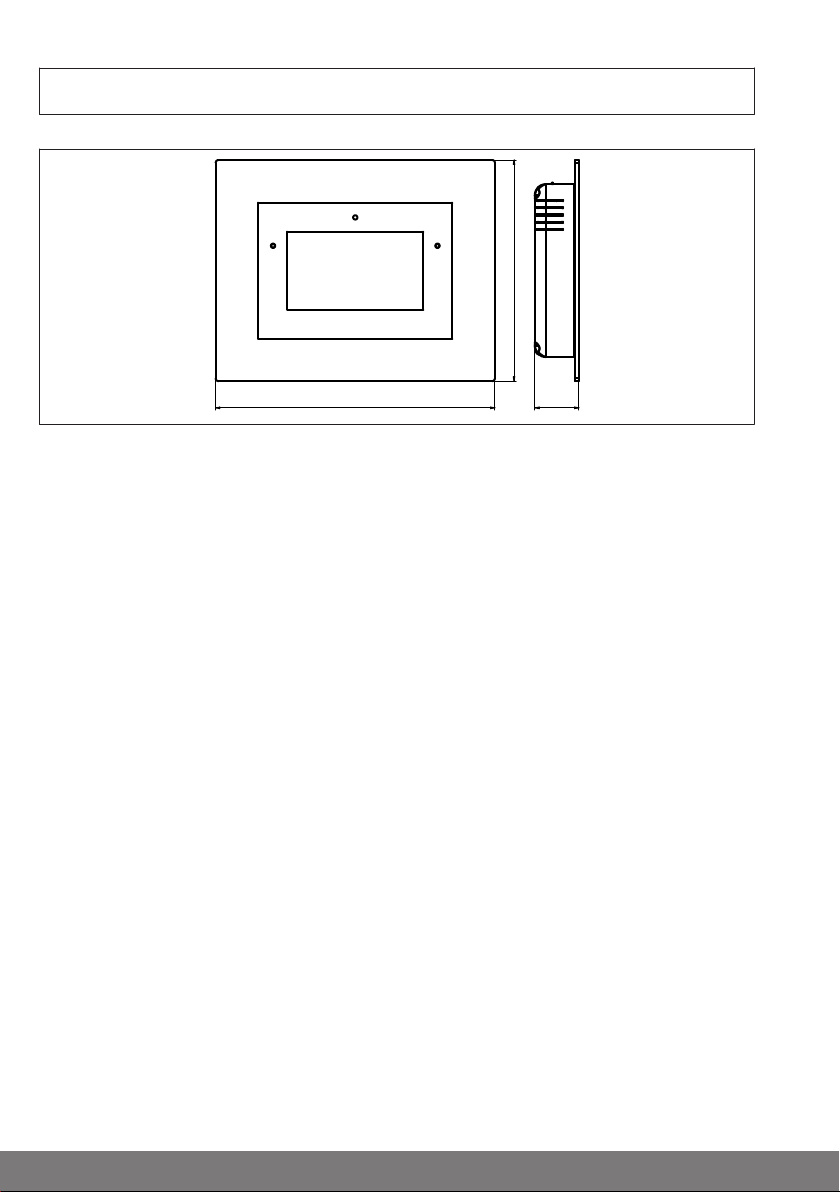
All dimensions in mm.
156
197 32
Dimensions
6
Page 7
1
2345
6
7 8 9
10
11
12
13
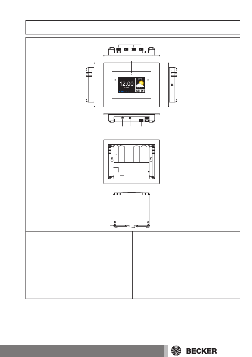
Device overview
1. Loudspeaker
2. LAN connection
3. WLAN connection
4. Headphone output, 3.5 mm
5. Mains connection
6. Microphone
7. Operating status LED
8. Integrated front camera
9. Light sensor
10. USB connections for:
- KNX stick
- Centronic stick
- Flash memory
- Free
11. Reset button
12. Cover
13. Feet
7
Page 8
Online documentation
In addition to the present commissioning instructions, we make comprehensive docu‐
mentation available to you online.
Please visit the following Internet site:
http://www.becker-antriebe.net/cc51-manual.
Mains connection
1. Pull the cover off the control unit.
2. First connect the mains adapter to the control unit, then plug it into the socket.
3. The starting screen appears.
4. Now put the cover back onto the control unit.
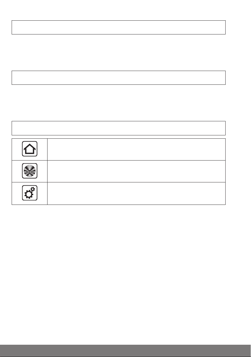
Menu structure
Home screen
My house
Settings and applications
8
Page 9

Home screen
1
2
4
3
1. Display the current weather
2. Basic menu
3. Status indications
4. Time / date
My house
▪ Rooms
▪ Groups
▪ Scenarios
Settings and applications
▪ Cameras
▪ Radio
▪ Configuration
▪ Installation
▪ System information
9
Page 10

Commissioning, step-by-step
Set the language
1. Press the button in order to open the "Settings and applications" menu.
2. Now press the " Configuration" button followed by the "Set language" button.
3. Then select the desired language.
4. Now confirm your input with .
5. Press the " " button to close the menu.
Establishing the network and Internet connections
Note
An Internet connection is necessary for some functions.
In order to be able to use these functions, make sure that the CC51 is
connected to your network, that there is an Internet connection, and
that the time and date are set correctly.
Do remember that this may result in charges, depending on the con‐
tractual conditions of your Internet supplier.
1. Press the button in order to open the "Settings and applications" menu.
2. Now press the " Configuration" button followed by the "Network settings" button.
3. If you want to make the connection to your network over a LAN cable, then select
"Ethernet". Otherwise, select "Wi-Fi", and enter the necessary access data for your
wireless network.
4. Under network configuration, select whether this should be done by means of
DHCP or manually. If configuring manually, enter the following data: IP address,
subnet mask, gateway and name server
5. Now confirm your entries with .
Making a connection via LAN
1. Pull the cover off the control unit.
2. Connect the LAN cable to the control unit.
3. The LAN symbol appears on the main display when the connection is successful.
4. Now put the cover back onto the control unit.
Caution
Lay the LAN cable in such a way that nobody can tread on it or trip over
it.
Making a connection via WLAN
1. Press the button in order to open the "Settings and applications" menu.
2. Now press the " Configuration" button followed by the "Network settings" button.
10
Page 11

3. Then select Wi-Fi under "Interface".
4. Now enter the SSID of the selected route, and confirm the entry with .
5. Then enter the key (PSK) and confirm the entry with .
6. Now close the menu using the button.
7. Now enter the "Restart" button, and confirm the entry with .
8. The WLAN symbol appears on the main display when the connection is
successful.
Set the date and time
1. Press the button in order to open the "Settings and applications" menu.
2. Now press the " Configuration" button followed by the "Date and time" button.
3. If an Internet connection is available, select "Automatic (NTP)". Otherwise, choose
"Manual", and enter the date and the time.
4. Select the time and date formats and the time-zone that you want.
5. Now confirm your input with .
6. Press the " " button when you want to close the menu.
Weather location
Note
An Internet connection is necessary for this function.
1. Press the button in order to open the "Settings and applications" menu.
2. Now press the " Configuration" button followed by the "Weather location" button.
3. Enter the desired weather location.
4. Confirm your input with .
5. If applicable, enter the desired location from the displayed list.
6. Now confirm your input with .
7. Press the " " button when you want to close the menu.
Add a B-Tronic / KNX receiver
1. Press the button in order to open the "Settings and applications" menu.
2. Now press the " House installation" button followed by the "Receivers" button.
3. Press the "+" button.
4. Now enter the name of the receiver.
5. Then select the receiver type and the device type.
6. Confirm your entries with .
7. Now put the receiver into programming mode as described in the receiver's in‐
structions.
8. Then start programming with .
9. Successful programming is shown on the display.
11
Page 12

10. It may be necessary to confirm the receiver, depending on which functions are
available. Please see the receiver's instructions for the type and extent of the con‐
firmation.
11. Continue with all the other B-Tronic / KNX receivers as described above.
12. Press the " " button when you want to close the menu.
Add a Centronic receiver
1. Press the button in order to open the "Settings and applications" menu.
2. Now press the " House installation" button followed by the "Receivers" button.
3. Press the "+" button.
4. Now enter the name of the receiver.
5. Then select the receiver type and the device type.
6. Confirm your entries with .
7. Now put the receiver with the programmed master transmitter into programming
mode as described in the receiver's instructions.
8. Then start programming with .
9. Successful programming is confirmed on the display.
10. It may be necessary to confirm the receiver, depending on which functions are
available. Please see the receiver's instructions for the type and extent of the con‐
firmation.
11. Continue with all the other Centronic receivers as described above.
12. Press the " " button when you want to close the menu.
Create rooms
1. Press the button in order to open the "Settings and applications" menu.
2. Now press the " House installation" button followed by the "Rooms" button.
3. Press the "+" button.
4. Now give the room a name.
5. Confirm your entries with .
6. Continue with all the rooms that are to be set up as described above.
7. Press the " " button when you want to close the menu.
Add receivers to rooms
1. Press the button in order to open the "Settings and applications" menu.
2. Now press the " House installation" button followed by the "Rooms" button.
3. Select the room you want.
4. Press the "+" button in order to see the list of receivers that have not yet been as‐
signed to the rooms.
5. Select the receiver that you want to be assigned to the room.
6. Continue with all the receivers that are to be included in this room as described
above.
7. Press the " " button when you want to close the menu.
12
Page 13

Create groups
Note
Groups can only consist of receivers of the same type.
Just like receivers, groups can be assigned to rooms.
1. Press the button in order to open the "Settings and applications" menu.
2. Now press the " House installation" button followed by the "Groups" button.
3. Press the "+" button.
4. Select the type of receiver that you want.
5. Now give the group a name.
6. Confirm your entries twice by pressing .
7. Continue with all the groups that are to be created as described above.
8. Press the " " button when you want to close the menu.
Add receivers to groups
Note
Groups can only consist of receivers of the same type.
1. Press the button in order to open the "Settings and applications" menu.
2. Now press the " House installation" button followed by the "Groups" button.
3. Select the group that you want.
4. Press the "+" button in order to see the list of receivers.
5. Select the receivers that you want to be assigned to the group.
6. Continue with all the receivers that are to be included in this group as described
above.
7. Press the " " button when you want to close the menu.
13
Page 14

Operation
11
22
121
2
11
22
Operating receivers
1. Press the button in order to open the "My house" menu.
2. Now select the room you want.
3. Then choose the receiver that is to be operated.
4. You can now operate the receiver.
5. Press the " " button when you want to close the menu.
Tubular drive receivers
Note
With B-Tronic receivers you get feedback on the current status and
have the option of tapping the desired position on the status display in
order to initiate a corresponding drive command.
UP button
STOP button
DOWN button
Intermediate position 1
Intermediate position 2
Status display
14
Page 15

Dimmer receiver
121
2
121
2
11
22
Note
With B-Tronic receivers you get feedback on the current status and
have the option of tapping the desired position on the status display in
order to initiate a corresponding dimming command.
UP button
STOP button
DOWN button
Intermediate position 1
Intermediate position 2
Status display
Switch receivers
Note
With B-Tronic receivers you get feedback on the current status.
15
Page 16

ON button
OFF button
Status display
Operating groups
Note
Groups can only consist of receivers of the same type.
Just like receivers, groups can be assigned to rooms.
1. Press the button in order to open the "My house" menu.
2. Then press the "Groups" button.
3. Then select the group that you want.
4. You can now operate the group. Operation is performed as described for each re‐
ceiver type.
5. Press the " " button when you want to close the menu.
16
Page 17

Extended configuration
Screen settings
1. Press the button in order to open the "Settings and applications" menu.
2. Now press the " Configuration" button followed by the "Screen settings" button.
3. You can make the following settings in this menu:
▪ Display the time
▪ Display the weather
▪ LCD brightness
▪ Starting screen (time before returning to the starting screen)
▪ Screen off (time until the screen is switched off)
1. Confirm your entries with .
2. Press the " " button when you want to close the menu.
Backing up and restoring
Note
Make sure that the supplied Flash memory is plugged into the slot
provided for it.
1. Press the button in order to open the "Settings and applications" menu.
2. Now press the " Configuration" button followed by the "Backup and restore"
button.
3. In this menu you can backup the current configurations or, if one exists, restore an
existing backup.
4. Press the appropriate button.
5. Confirm your entries with .
6. Press the " " button when you want to close the menu.
Updating the system software
Note
Make sure that the supplied Flash memory is plugged into the slot
provided for it.
An Internet connection is necessary for this function.
1. Press the button in order to open the "Settings and applications" menu.
2. Now press the " Configuration" button followed by the "Update" button.
3. If a new version is available, you can download it through the "Download now and
install?" button. The new version is installed automatically.
4. The device automatically restarts.
17
Page 18

Factory default settings
1. Press the button in order to open the "Settings and applications" menu.
2. Now press the " Configuration" button followed by the "Factory settings" button.
3. In this menu you can reset ALL the settings to the factory default.
4. Confirm your entries with .
5. ALL settings are reset. The device must now be restarted. Do this by pressing the
"Restart" button.
Restart
1. Press the button in order to open the "Settings and applications" menu.
2. Now press the " Configuration" button followed by the "Restart" button.
3. You can restart the device in this menu.
4. Confirm your input with .
5. Press the " " button when you want to close the menu.
Access data
Note
An Internet connection is necessary for this function.
Request a login code
A login code is required in order to set up gateway access.
1. Open the "Access data" menu ( -> -> Access data)
2. Now press the "Request and display login code?" button.
Note
The code that is displayed is valid for the next 30 minutes.
First login over the Internet
1. Enter the following address in your browser: http://gw.b-tronic.net
2. Then click on "No access data yet?"
3. Now complete "Your registration" fully.
4. Now press the "Save" button.
5. A confirmation e-mail will be sent to the e-mail address that you have entered. You
must confirm this.
6. You can now login at "http://gw.b-tronic.net " using your e-mail address or your
name, and your password.
18
Page 19

Caution
138
66
73
Lay the mains connecting cable in such a way that nobody can tread on
it or trip over it.
Wall mounting
Table stand
Installation
1. Check that the transmitter and receiv‐
er, and the WLAN if present, are
working properly before mounting in
the desired position.
2. Fasten the bracket to the wall using
the two enclosed screws.
1. Check that the transmitter, receiver
and, if present, WLAN function proba‐
bly at the mounting position.
2. Open the feet of the stand to 90°.
Cleaning
Only clean the device with a damp cloth. Do not use cleaning agents, as they may dam‐
age the plastic.
19
Page 20

Technical data
Supply voltage 230 V/50 Hz
Degree of protection IP 20
Permissible ambient temperature and air humidi‐ty0 °C to +55 °C at a relative humidity
of between 20 % and 80 % (noncondensing)
Radio frequency 868.3 MHz
CPU ARM9 454 MHz
Memory 128 MB
Display 10.9 cm / 4.3 inch touchscreen
Resolution: 480 x 272 pixels
Camera 640 x 480 pixels, VGA RGB
Operating system Linux
Dimensions (W x H x D) 197 x 156 x 34 mm
Connections
USB WLAN stick IEEE802.11n
WPA / WPA2
USB Flash stick 1 GB
USB Centronic RF stick 868.3 MHz
USB KNX stick 868.3 MHz
Ethernet 10 / 100 TBase
Headset 3.5 mm jack
The maximum radio range on and in the building is 25 m and in the open 350 m.
20
Page 21

General Declaration of Conformity
Becker-Antriebe GmbH declares that the B-Tronic CentralControl CC51 device com‐
plies with the fundamental requirements and other relevant guidelines of Directive
R&TTE 1999/5/EC.
Intended for use in the following countries: EU, CH, NO, IS, LI
Subject to technical changes without notice
21
Page 22

22
Page 23

Page 24

4035 630 029 0 04/02/2013
 Loading...