

Becker BXP6402-1R-01, BXP6402-2R-02 Installation And Operation Manual

Remote Controlled
Manual DV69802.03
Transponder
Mode S Level 2es
BXP6402
BXP6402-1R-(XX) Class 1
BXP6402-2R-(XX) Class 2
Software Versions:
upwards from Software Version
DSP: SCI1026S305 Version 47
FPGA: SCI1039S305 Version 55
Becker Avionics GmbH • Baden-Airpark B108 • 77836 Rheinmünster • Germany
Installatio n and Operation
Issue 04 June 2018
Article-No. 0584.071-071
+49 (0) 7229 / 305-0 • Fax +49 (0) 7229 / 305-217
http://www.becker-avionics.com • E-mail: info@becker-avionics.com
Installation and Operation
Contact data for:
Europe, Asia,
Becker Avionics GmbH
Contact data for:
America,
Becker Avionics Inc
industry standards and the requirements of the responsible aviation authority. The product
Approved Production and Maintenance Organization
Certificates see: http://www.becker-avionics.com/company-about/ →Certificates
Oceania and
Africa
Australia, Japan
Baden-Airpark B108
77836 Rheinmünster (Germany)
Tel.: + 49 (0) 7229 / 305-0
Fax: + 49 (0) 7229 / 305-217
Internet: www.becker -avionics.com
Email: info@becker-avionics.com
Customer Service:
Email: support@becker-avionics.com
Email: info@beckerusa.com
WARNING - USER RESPONSIBILITY
FAILURE OR IMPROPER SELECTION OR IMPROPER USE OF THE PRODUCTS DESCRIBED
HEREIN OR RELATED ITEMS CAN CAUSE DEATH, PERSONAL INJURY AND PROPERTY
DAMAGE.
This document and ot her inform ation from Becker Avionics GmbH prov ide produc t or system opti ons
for further investigation by users having technical knowledge.
The user is responsib le for m ak ing the final se lect ion of the s ystem and com ponents . The us er has to
assure that all perform ance, endurance, m aintenance, safety requirem ents of the app lication are met
and warnings be observed.
For this the user has to include all aspects of the application to be compliant with the applicable
documentations from Becker Avionics GmbH have to be observed.
To the extent that Bec ker Avionics G mbH provide co mponent or system options based up on data or
specifications provided by the user, the user is responsible for determining that such data and
specifications are suit able and sufficient for all applic ations and reasonably fores eeable uses of the
components or systems.
Term definition: User in the sense of user, installer, installation company.
2 BXP6402 DV69802.03 Issue 04 June 2018
Installation and Operation
Preface
Dear Customer,
Thank you for purchasing a Becker Avionics product.
We are pleased that you have chosen our product and we are confident that it will meet your
expectations.
For development and m anufacturing of our product, the guidelines for highest quality and reliability
have been borne in m ind, supplemented by selection of high quality material, re sponsible production
and testing in accordance to the corresponding standards.
Our competent customer support department will respond on any technical question you may have.
Please do not hesitate to contact us at any time.
Transponder Design
BXP6402
(Remote controlled Transponder)
DV69802.03 Issue 04 June 2018 BXP6402 3

Installation and Operation
Document: DV69802.03 / issue 04 Article Number 0584.071-071
Added: Address box, User responsibility.
List of Effective Pages and Changes
Only technical relevant modifications are described in this table.
Cover Page 06/2018
Introduction 06/2018
Chapter 1 –4 06/2018
Issue Page No.:
Section /
Chapter
Description
04 all all Changed: Editorial adjustments.
-- Introduction
Updated: User information.
-- 2.4.3 Changed: Dimension drawing AM6400.
-- 2.5.12 Updated: GPS Configuration.
--
--
--
--
--
--
--
--
--
--
--
© by Becker Avionics GmbH / all rights reserved
4 BXP6402 DV69802.03 Issue 04 June 2018

Installation and Operation
Table of Contents
1. General Description .................................................................................................................... 11
1.1. Introduction.................................................................................................................................. 12
1.2. Purpose of Equipment ................................................................................................................. 13
1.3. Variants Overview ....................................................................................................................... 14
1.3.1. Software Status ................................................................................................................. 14
1.4. Safety-Conscious Utilization ....................................................................................................... 15
1.5. Restriction for Use ....................................................................................................................... 15
1.6. Technical Data ............................................................................................................................ 16
1.6.1. Electrical Characteristics................................................................................................... 16
1.6.2. Transmitter Data ............................................................................................................... 17
1.6.3. Receiver Data ................................................................................................................... 18
1.6.4. Dimensions & Weight........................................................................................................ 18
1.6.5. Software ............................................................................................................................ 18
1.6.6. Environmental Condition ................................................................................................... 19
1.6.7. Certifications ..................................................................................................................... 20
1.7. Order Code.................................................................................................................................. 21
1.7.1. BXP6402 ........................................................................................................................... 21
1.7.2. Accessories ....................................................................................................................... 21
2. Installation .................................................................................................................................... 23
2.1. Packaging, Transport, Storage ................................................................................................... 24
2.1.1. Packaging Material and Transport .................................................................................... 24
2.2. Device Assignment ..................................................................................................................... 24
2.2.1. Scope of Delivery .............................................................................................................. 24
2.2.2. Additional Required Equipment ........................................................................................ 24
2.2.3. Type Plate ......................................................................................................................... 25
2.2.4. Software/Firmware Status – Functionality ........................................................................ 25
2.3. Mounting Requirements .............................................................................................................. 26
2.3.1. Order of Installation ........................................................................................................... 26
2.3.2. Blind Encoder (BE6400) ................................................................................................... 26
2.3.3. Antenna 1A032 ................................................................................................................. 26
2.4. Dimensions.................................................................................................................................. 27
2.4.1. Transponder BXP6402-XR-(XX) ....................................................................................... 27
2.4.2. Transponder BXP6402-XR-(XX) with Mounting Kit MK4401............................................ 28
2.4.3. Address Module AM6400-1-(01) ....................................................................................... 29
2.4.4. Blind Encoder BE6400 ...................................................................................................... 29
2.4.5. Antenna 1A032 ................................................................................................................. 30
2.5. Electrical Installation ................................................................................................................... 31
2.5.1. Grounding ......................................................................................................................... 31
2.5.2. BXP6402 Connector Layout ............................................................................................. 32
2.5.3. Connector J6 ..................................................................................................................... 32
2.5.4. Connector P9 (Dsub 25-pol male) .................................................................................... 32
2.5.5. Connector J8 (Dsub 25-pol female) .................................................................................. 33
2.5.6. Connector J7 (5-pol female) ............................................................................................. 35
2.5.7. External Suppression ........................................................................................................ 35
2.5.8. External IDENT Push-Button ............................................................................................ 35
2.5.9. Ground Switch .................................................................................................................. 35
2.5.10. Programming of the Address Module ............................................................................... 36
2.5.11. Avionics Data Transfer...................................................................................................... 36
2.5.12. GPS Configuration ............................................................................................................ 37
2.5.13. Remote Control ................................................................................................................. 38
2.6. Settings after Installation ............................................................................................................. 39
2.7. Warning and Failure Indications ................................................................................................. 40
2.8. Aircraft Wiring .............................................................................................................................. 40
2.8.1. BXP6402 with Parallel Encoding Altimeter & GPS Receiver............................................ 41
2.8.2. BXP6402 with Serial Encoding Altimeter & GPS Receiver .............................................. 42
DV69802.03 Issue 04 June 2018 BXP6402 5

Installation and Operation
2.8.3. BXP6402 with Serial Encoding Altimeter (Cutout) ............................................................ 43
2.8.4. BXP6402 with RS232 GPS Receiver (Cutout) .................................................................. 43
2.9. Check after Installation ................................................................................................................ 44
2.9.1. Pre-Flight Check Using Self -Test ...................................................................................... 44
2.9.2. Check of the Address Module ........................................................................................... 44
2.9.3. Test and Adjustment of Transmit Frequency .................................................................... 44
2.9.4. Check of Transmit Power .................................................................................................. 44
3. Operating Instructions ................................................................................................................ 45
3.1. Device Description....................................................................................................................... 45
3.1.1. Device Assignment ........................................................................................................... 45
3.1.2. Packing, Transport, Storage ............................................................................................. 45
3.1.3. Scope of Delivery .............................................................................................................. 45
3.1.4. Type Plate ......................................................................................................................... 45
3.2. Operating with CU6401 Control ler .............................................................................................. 45
3.3. Operating with OEM Controller ................................................................................................... 45
4. Index .............................................................................................................................................. 48
List of Figures
Figure 1: Type Plate (example) .............................................................................................................................. 25
Figure 2: Transponder BXP6402-XR-(XX) ............................................................................................................. 27
Figure 3: Mounting Kit MK4401 .............................................................................................................................. 28
Figure 4: Address Module AM6400-1-(01) ............................................................................................................. 29
Figure 5: Blind Encoder BE6400 ............................................................................................................................ 29
Figure 6: Antenna 1A032 ....................................................................................................................................... 30
Figure 7: BXP6402 Connector Layout .................................................................................................................... 32
Figure 8: BXP6402 with Parallel Encoding Altimeter & GPS Receiver ................................................................... 41
Figure 9: BXP6402 with Serial Encoding Altimeter & GPS Receiver ..................................................................... 42
Figure 10: BXP6402 - Serial Encoding Altimeter Connection (not for BE6400) ..................................................... 43
Figure 11: BXP6402 - RS232 GPS Receiver Connection (not with BE6400) ......................................................... 43
6 BXP6402 DV69802.03 Issue 04 June 2018

List of Abbreviations
AA
Aircraft Address (24-bit ICAO)
ACAS
Airborne Collision Avoidance System
A/D
Analog/Digital
ADLP
Avionics Data Link Processor
ADS
Comm-A Definition Subfield
ADS-B
Automatic Dependent Surveillance-Broadcast
AI
Aircraft Identifier
AICB
Air Initiated Comm-B
ALT
Altitude or Transponder ALT Mode
AM
Address Module
ARINC
Aeronautical Radio Incorpo rat ed
ATC
Air Traffic Control
ATCRBS
Air Traffic Control Radar Beacon System (US only)
BIT
Built-In Test
BITE
Built-In Test Equipment
CBIT
Continuous Built-In Test
Comm-A
112-bit interrogation containing the 56-bit message field (uplink)
Comm-B
112-bit reply containing the 56-bit message field (downlink)
Class 1
XPDR with transmit power ≥ +21 dBW (125 W) at antenna foot and ≥ 250 W at
Class 2
XPDR with transmit power ≥ +18.5 dBW (70 W) at antenna foot and ≥ 140 W at
CU
Control Unit
DC
Direct Current
Diversity
Diversity receiving and transmitting with two antennas
DME
Distance Measurement Equipment
DPSK
Differential Phase Shift Keying
DV
Document Identification Number
EASA
European Aviation Safety Agency
ELS
Elementary Surveillance, XPDR mode S supports the altitude and the downlinked
EHS
Enhanced Surveillance, XPDR mode S supports additional parameters to
es
e = Extended squitter and s = SI capability
ETSO
European Technical Standard Order
EUROCAE
European Organization for Civil Aviation Equipment
FAA
Federal Aviation Administration
FL
Flight Level
FMS
Flight Management System
FN
Flight Number
List of Abbreviations
Installation and Operation
equipment output, altitude up to 50 000 ft., aircraft speed > 175 kt.
equipment output, altitude up to 15 000 ft., aircraft speed > 175 kt.
aircraft identification (unique ICAO-24-bit-address)
e.g. heading, speed and selected vertical intention
DV69802.03 Issue 04 June 2018 BXP6402 7

Installation and Operation
List of Abbreviations
GICB
Ground Initiated Comm-B
GND
Ground
GPS
Global Positioning System
IBIT
Initiated Built-In Test
IC
Integrated Circuit
ICAO
International Civil Aviation O r ganizat io n
ID
Identifier
IDT
Ident (Identification)
IFR
Instrument Flight Rules
I/O
Input and/or Output
Level 2es
Surveillance with Comm A/B capability (transmitting and receiving with data block
LCD
Liquid Crystal Display
Mode S
S = Selective Interrogation of the Transponder
MTL
Minimum Triggering Level
ON
Transponder ON mode (without altitude transmission)
PAM
Pulse Amplitude Modulation
PBIT
Power-on Built-In Test
PN
Part Number
PS
Power Supply
R
Reply
RF
Radio Frequency
RX
Receiver
SBY
Standby mode
SEL
Selection
SI
Surveillance Identifier
SPI
Special Position Identification Pulse
SSR
Secondary Surveillance Radar
STO
Store
SUPP
Supply Voltage DC
TCAS
Traffic Alert and Collision Avoidance System (US)
TIS
Traffic Information Service
TIS-B
Traffic Information Service-Broadcast
TNC
Threaded Naval Connector (coaxial)
TSO
Technical Standards Order
TX
Transmitter
VFR
Visual Flight Rules
VSWR
Voltage Standing Wave Ratio
XPDR
Transponder
up to 112 bit). e = Extended squitter and s = SI capability
8 BXP6402 DV69802.03 Issue 04 June 2018
Units
Units
A
Ampere
mA
Milliampere
°C
Degree Celsius
cm
Centimetre
dBm
Power Ratio In Decibel referenced to 1 mW
dB
Decibel
g
Gram
kg
Kilogram
Hz
Hertz
kHz
Kilohertz
MHz
Megahertz
mm
Millimetre
Nm
Nautical Mile
Ohm (Ω)
Resistance
s
Second
V
Volt
mV
Millivolt
W
Watt
"
Inch
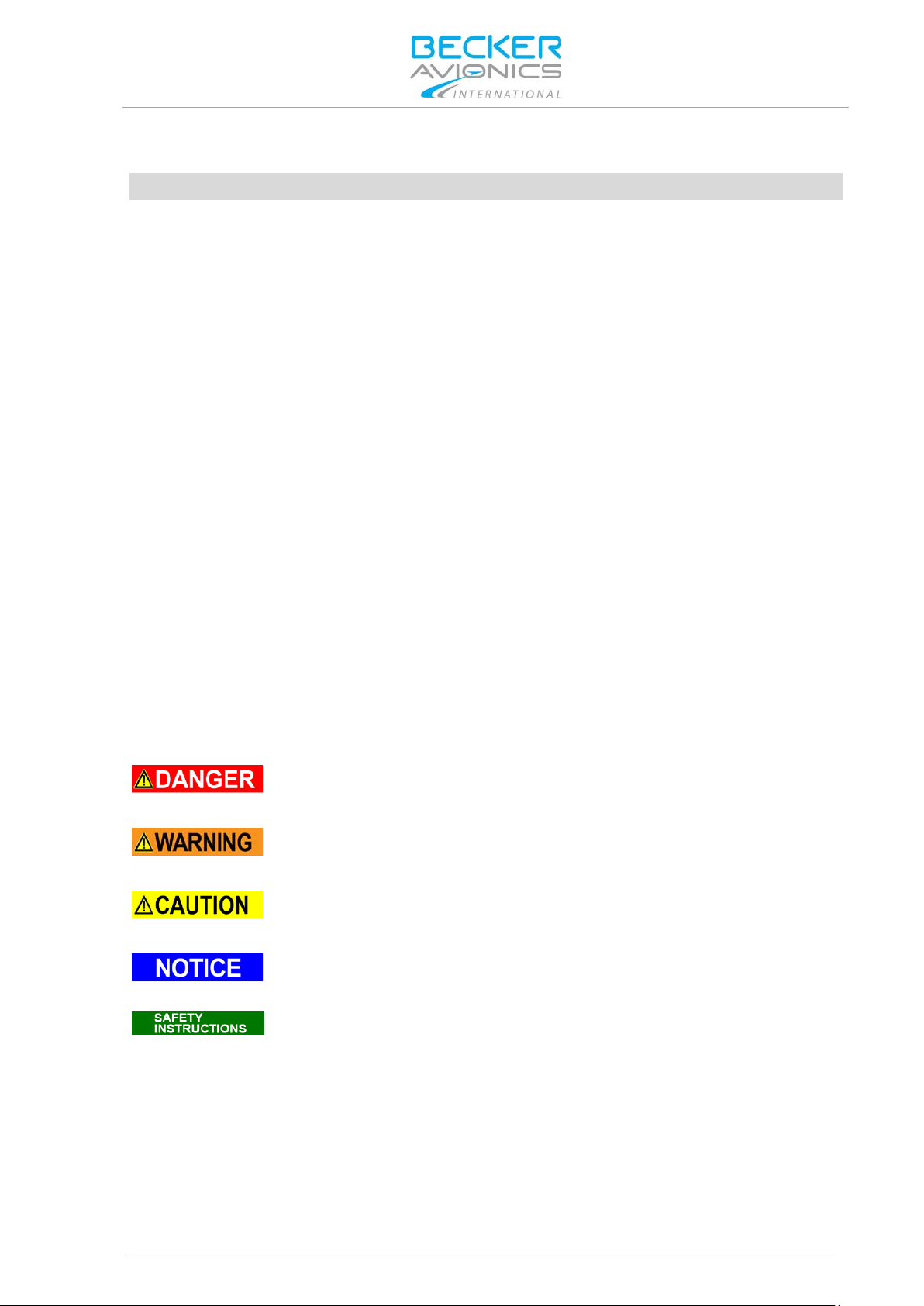
Indicates a hazardous situation which, if not avoided, will result in death or
Indicates a hazardous situation which, if not avoided, could result in death or
Indicates a hazardous situation which, if not avoided, could result in minor or
Is used to address practices not related to physical injury.
Safety instructions (or equivalent) signs indicate specific safety-related
Installation and Operation
General Safety Definitions
serious injury.
serious injury.
moderate injury.
instructions or procedures.
DV69802.03 Issue 04 June 2018 BXP6402 9
Installation and Operation
The packaging material is inflammable, if it is disposed of improperly by
The device(s) may be installed on an aircraft only by an approved aer on aut ical
The user is responsible for protective covers and/or additional safety measures in
Disposal
burning, toxic fumes may develop.
This product contains materials that fall under the special disposal regulation, which corresponds to
the EC directive for dangerous disposal material. We recommend disposing of the respective materials
in accordance with the respectively valid environmental laws.
Dispose circuit boards via a technical waste dump which is allowed to take on e.g. electrolytic
aluminium capacitors. Do under no circumstances dump the circuit boards with normal waste dump.
Warranty Conditions
company (e.g. EASA Part 145) which shall also examine and verify the
User conversions and changes are not permitted.
Any change made by the u ser excludes any liabilit y on our part (excluding th e work described in th is
manual).
• The device must not be opened.
• Do not make any modifications to the device, except for those described in the manual.
• Make connections to the inputs, outputs and interfaces only in the manner described in
the manual.
• Fix the devices according to the mounting instructions.
We cannot provide any guarantee for other mounting methods.
installation.
Conditions of Utilization
General introductory notes
With this device you bought a product whic h was manufactured and tes ted before delivery with th e
utmost care.
Please take your tim e to read the follo wing notes which you ought to follo w closely during ins tallation
and operation.
Otherwise all claim s under the warranty wi ll becom e void and a reduced s ervice life or even d am ages
must be expected.
order to prevent damages to persons and electric accidents.
Additional Conditions of Utilization
Please refer to "Safety-Conscious Utilization", page 15.
Non-Warranty Clause
We checked the co nte nts o f this publication for com pli anc e with th e as soc ia ted h ar d a nd s of t ware. We
can, however, not exclude discrepancies and do therefore not accept any liability for the exact
compliance. The inf orm atio n in this p ublic ation is r egular ly chec ked, neces sar y co rrec tions will be par t
of the subsequent publications.
10 BXP6402 DV69802.03 Issue 04 June 2018

General Description
Introduction
1. General Description
In this chapter you can read about:
1.1. Introduction.................................................................................................................................. 12
1.2. Purpose of Equipment ................................................................................................................. 13
1.3. Variants Overview ....................................................................................................................... 14
1.3.1. Software Status ................................................................................................................. 14
1.4. Safety-Conscious Utilization ....................................................................................................... 15
1.5. Restriction for Use ....................................................................................................................... 15
1.6. Technical Data ............................................................................................................................ 16
1.6.1. Electrical Characteristics................................................................................................... 16
1.6.2. Transmitter Data ............................................................................................................... 17
1.6.3. Receiver Data ................................................................................................................... 18
1.6.4. Dimensions & Weight........................................................................................................ 18
1.6.5. Software ............................................................................................................................ 18
1.6.6. Environmental Condition ................................................................................................... 19
1.6.7. Certifications ..................................................................................................................... 20
1.7. Order Code.................................................................................................................................. 21
1.7.1. BXP6402 ........................................................................................................................... 21
1.7.2. Accessories ....................................................................................................................... 21
The remote controlled Mode S transponder BXP6402-XR-(XX) forms together with a control unit
(e.g. CU6401) an airborne component of the Air Traffic Control (ATC). It works as a Mode S
Secondary Surveillance Radar system with added ADS-B Transmitting Subsystem functionality.
In the selective m ode (Mode S), the Ground Co ntrol c an inter rogate the transp onder ind ividually using
an ICAO 24-bit address, which is unique to the particular aircraft.
BXP6402-XR-(XX) works as a part of the surveillance system in two ways:
• As Mode S transponder which provides responses to ground station interrogations and
allows air traffic control (ATC) to locate, identify and track aircraft.
• As ADS-B Broadcast-Only System which continuously transmits aircraft information.
DV69802.03 Issue 04 June 2018 BXP6402 11

General Description
DV69802.04
DV69802.03
General X X
Installation X X
Operation X X
Theory of Operation
X
N/A
Maintenance and Repair
X
N/A
Illustrated Parts List
X
N/A
Modification and Changes
X
N/A
Circuit Diagrams
X
N/A
Certifications X N/A
Attachments X N/A
Introduction
1.1. Introduction
This manual describes the installation and operation of the Mode S transponder BXP6 402-XR-(XX).
The ID label on your device shows the part number for identification purposes (see "Type Plate",
page 25).
Before starting operation of the unit(s) please read this manual carefully, with particular attention to the
description referring to your device(s). This manual also contains several optional elements of the
system (Blin d encoder for example) that m ay not be contained in your delivery package and in t hat
case are not applicable.
For further descriptions we are using the term BXP6402 instead of writing the complete model
number.
The manuals “Maintenance and Repair” (M&R) and “Installation and Operation (I&O) contain the
following sections:
Section
M&R
I&O
12 BXP6402 DV69802.03 Issue 04 June 2018

Actual generation of each ADS-B message type and data within each message
General Description
Purpose of Equipment
1.2. Purpose of Equipment
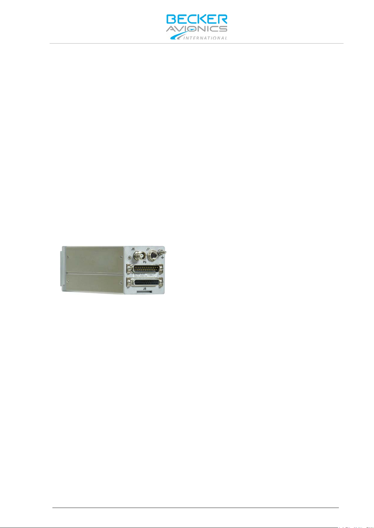
The BXP6402 transponder is a remote controlled unit designed for installation in the avionic
compartment of aircraft.
• All connectors for connection to the aircraft interwiring, adddress module, antenna and
altitude encoder are located at the rear side of the unit.
• Serial interfaces RS422 are available at the unit connectors.
o Control via: Control unit CU6401.
o Control via: "External" unit (e.g. ADLP).
• Easy mounting; to meet the conditions for certification use the mounting method with
Mode S features:
mounting kit MK4401.
• Individual interrogation of the transponder ICAO 24-bit address.
• Support of the SI code (Surveillance Identifier).
• Register capability for elementary surveillance (ELS) and enhanced surveillance (EHS).
• Extended squitters transmission.
• Data link capability.
• GPS receiver connection capability.
• ADS-B Broadcast-Only System Class B0 e.g. broadcasts following data:
o Airborne Position Message
o Surface Position Message
o Airborne Velocity Message
o Extended Squitter Aircraft Status Message
Inherent features:
• Mode A - in this mode, the 4096 character code set on the control head is sent as a reply
to interrogation from a ground station.
• Mode C - in this mode, the encoded altitude is sent in addition to the mode A reply.
The altitude information must be delivered from an external device (e.g. Becker Blind
Encoder BE6400).
• A special identifier pulse (SPI) can be activated by pressing the IDT button in Mode A/C
and Mode S.
• Selftests (BITs). The Initiated Built-In Test (IBIT), the Continuous Built-In Test (CBIT) and
the Power-on Built-In Test (PBIT) are integrated in the transponder.
depends on availability of navigation data and GPS engine capabilities.
DV69802.03 Issue 04 June 2018 BXP6402 13
General Description
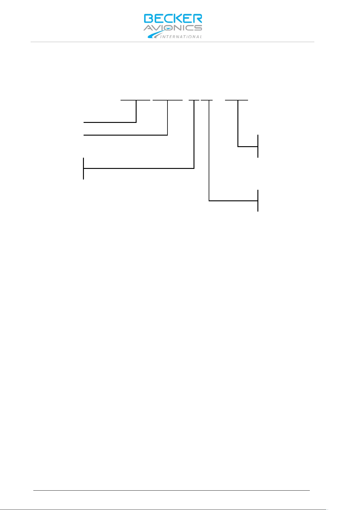
BXP
6402
-
X R - (
X X
)
Identifier
Model Number
01= Standard
XPDR Class
1= Class 1
2= Class 2
Design
Variants Overview
1.3. Variants Overview
Within the part number, the meaning of "-XR-(XX) " is:
1.3.1. Software Status
Descriptions see "Software/Firmware Status – Functionality", page 25.
Options
R= Remote Controlled
14 BXP6402 DV69802.03 Issue 04 June 2018

Excessive pulses on the DC bus of the aircraft may cause damage on electrical
The BXP6402 is to be used inside the declared limits.
1.4. Safety-Conscious Utilization
For safe operation of the product the following notes have to be observed:
• The installation of the Mode S transponder into an aircraft may be carried
out only by an authorized installation company. The country regulations
always have to be observed.
• Use the product only within the specified conditions, see "Technical Data"
page 16.
Power supply:
• Do not connect the unit to AC sources.
• Make sure that the unit is connected to the mandatory DC source, see
"Technical Data" page 16.
• Do not connect the unit with reversed polarity to the DC source.
Circuit breaker:
• If no load is connected to connector P9, pin 6, the unit should be protected
from the aircraft power supply by a dedicated 3 A circuit breaker.
• If an external load is connected to connector P9, pin 6, the circuit breaker
should be a 5 A type.
Address module:
• The programming of the address module AM6400-1 with the ICAO 24-bit
address of the aircraft must be carried out at an installation company or in
the manufacturer factory. A programming kit is available see "Order Code"
page 21.
General Description
Safety-Conscious Utilization
circuits of any installed instrument.
Do not switch ON the device during engine start or shutdown.
1.5. Restriction for Use
DV69802.03 Issue 04 June 2018 BXP6402 15
 Loading...