

Page 1

Remote Controlled
Manual DV69802.03
Transponder
Mode S Level 2es
BXP6402
BXP6402-1R-(XX) Class 1
BXP6402-2R-(XX) Class 2
Software Versions:
upwards from Software Version
DSP: SCI1026S305 Version 47
FPGA: SCI1039S305 Version 55
Becker Avionics GmbH • Baden-Airpark B108 • 77836 Rheinmünster • Germany
Installatio n and Operation
Issue 04 June 2018
Article-No. 0584.071-071
+49 (0) 7229 / 305-0 • Fax +49 (0) 7229 / 305-217
http://www.becker-avionics.com • E-mail: info@becker-avionics.com
Page 2
Installation and Operation
Contact data for:
Europe, Asia,
Becker Avionics GmbH
Contact data for:
America,
Becker Avionics Inc
industry standards and the requirements of the responsible aviation authority. The product
Approved Production and Maintenance Organization
Certificates see: http://www.becker-avionics.com/company-about/ →Certificates
Oceania and
Africa
Australia, Japan
Baden-Airpark B108
77836 Rheinmünster (Germany)
Tel.: + 49 (0) 7229 / 305-0
Fax: + 49 (0) 7229 / 305-217
Internet: www.becker -avionics.com
Email: info@becker-avionics.com
Customer Service:
Email: support@becker-avionics.com
Email: info@beckerusa.com
WARNING - USER RESPONSIBILITY
FAILURE OR IMPROPER SELECTION OR IMPROPER USE OF THE PRODUCTS DESCRIBED
HEREIN OR RELATED ITEMS CAN CAUSE DEATH, PERSONAL INJURY AND PROPERTY
DAMAGE.
This document and ot her inform ation from Becker Avionics GmbH prov ide produc t or system opti ons
for further investigation by users having technical knowledge.
The user is responsib le for m ak ing the final se lect ion of the s ystem and com ponents . The us er has to
assure that all perform ance, endurance, m aintenance, safety requirem ents of the app lication are met
and warnings be observed.
For this the user has to include all aspects of the application to be compliant with the applicable
documentations from Becker Avionics GmbH have to be observed.
To the extent that Bec ker Avionics G mbH provide co mponent or system options based up on data or
specifications provided by the user, the user is responsible for determining that such data and
specifications are suit able and sufficient for all applic ations and reasonably fores eeable uses of the
components or systems.
Term definition: User in the sense of user, installer, installation company.
2 BXP6402 DV69802.03 Issue 04 June 2018
Page 3
Installation and Operation
Preface
Dear Customer,
Thank you for purchasing a Becker Avionics product.
We are pleased that you have chosen our product and we are confident that it will meet your
expectations.
For development and m anufacturing of our product, the guidelines for highest quality and reliability
have been borne in m ind, supplemented by selection of high quality material, re sponsible production
and testing in accordance to the corresponding standards.
Our competent customer support department will respond on any technical question you may have.
Please do not hesitate to contact us at any time.
Transponder Design
BXP6402
(Remote controlled Transponder)
DV69802.03 Issue 04 June 2018 BXP6402 3
Page 4

Installation and Operation
Document: DV69802.03 / issue 04 Article Number 0584.071-071
Added: Address box, User responsibility.
List of Effective Pages and Changes
Only technical relevant modifications are described in this table.
Cover Page 06/2018
Introduction 06/2018
Chapter 1 –4 06/2018
Issue Page No.:
Section /
Chapter
Description
04 all all Changed: Editorial adjustments.
-- Introduction
Updated: User information.
-- 2.4.3 Changed: Dimension drawing AM6400.
-- 2.5.12 Updated: GPS Configuration.
--
--
--
--
--
--
--
--
--
--
--
© by Becker Avionics GmbH / all rights reserved
4 BXP6402 DV69802.03 Issue 04 June 2018
Page 5

Installation and Operation
Table of Contents
1. General Description .................................................................................................................... 11
1.1. Introduction.................................................................................................................................. 12
1.2. Purpose of Equipment ................................................................................................................. 13
1.3. Variants Overview ....................................................................................................................... 14
1.3.1. Software Status ................................................................................................................. 14
1.4. Safety-Conscious Utilization ....................................................................................................... 15
1.5. Restriction for Use ....................................................................................................................... 15
1.6. Technical Data ............................................................................................................................ 16
1.6.1. Electrical Characteristics................................................................................................... 16
1.6.2. Transmitter Data ............................................................................................................... 17
1.6.3. Receiver Data ................................................................................................................... 18
1.6.4. Dimensions & Weight........................................................................................................ 18
1.6.5. Software ............................................................................................................................ 18
1.6.6. Environmental Condition ................................................................................................... 19
1.6.7. Certifications ..................................................................................................................... 20
1.7. Order Code.................................................................................................................................. 21
1.7.1. BXP6402 ........................................................................................................................... 21
1.7.2. Accessories ....................................................................................................................... 21
2. Installation .................................................................................................................................... 23
2.1. Packaging, Transport, Storage ................................................................................................... 24
2.1.1. Packaging Material and Transport .................................................................................... 24
2.2. Device Assignment ..................................................................................................................... 24
2.2.1. Scope of Delivery .............................................................................................................. 24
2.2.2. Additional Required Equipment ........................................................................................ 24
2.2.3. Type Plate ......................................................................................................................... 25
2.2.4. Software/Firmware Status – Functionality ........................................................................ 25
2.3. Mounting Requirements .............................................................................................................. 26
2.3.1. Order of Installation ........................................................................................................... 26
2.3.2. Blind Encoder (BE6400) ................................................................................................... 26
2.3.3. Antenna 1A032 ................................................................................................................. 26
2.4. Dimensions.................................................................................................................................. 27
2.4.1. Transponder BXP6402-XR-(XX) ....................................................................................... 27
2.4.2. Transponder BXP6402-XR-(XX) with Mounting Kit MK4401............................................ 28
2.4.3. Address Module AM6400-1-(01) ....................................................................................... 29
2.4.4. Blind Encoder BE6400 ...................................................................................................... 29
2.4.5. Antenna 1A032 ................................................................................................................. 30
2.5. Electrical Installation ................................................................................................................... 31
2.5.1. Grounding ......................................................................................................................... 31
2.5.2. BXP6402 Connector Layout ............................................................................................. 32
2.5.3. Connector J6 ..................................................................................................................... 32
2.5.4. Connector P9 (Dsub 25-pol male) .................................................................................... 32
2.5.5. Connector J8 (Dsub 25-pol female) .................................................................................. 33
2.5.6. Connector J7 (5-pol female) ............................................................................................. 35
2.5.7. External Suppression ........................................................................................................ 35
2.5.8. External IDENT Push-Button ............................................................................................ 35
2.5.9. Ground Switch .................................................................................................................. 35
2.5.10. Programming of the Address Module ............................................................................... 36
2.5.11. Avionics Data Transfer...................................................................................................... 36
2.5.12. GPS Configuration ............................................................................................................ 37
2.5.13. Remote Control ................................................................................................................. 38
2.6. Settings after Installation ............................................................................................................. 39
2.7. Warning and Failure Indications ................................................................................................. 40
2.8. Aircraft Wiring .............................................................................................................................. 40
2.8.1. BXP6402 with Parallel Encoding Altimeter & GPS Receiver............................................ 41
2.8.2. BXP6402 with Serial Encoding Altimeter & GPS Receiver .............................................. 42
DV69802.03 Issue 04 June 2018 BXP6402 5
Page 6

Installation and Operation
2.8.3. BXP6402 with Serial Encoding Altimeter (Cutout) ............................................................ 43
2.8.4. BXP6402 with RS232 GPS Receiver (Cutout) .................................................................. 43
2.9. Check after Installation ................................................................................................................ 44
2.9.1. Pre-Flight Check Using Self -Test ...................................................................................... 44
2.9.2. Check of the Address Module ........................................................................................... 44
2.9.3. Test and Adjustment of Transmit Frequency .................................................................... 44
2.9.4. Check of Transmit Power .................................................................................................. 44
3. Operating Instructions ................................................................................................................ 45
3.1. Device Description....................................................................................................................... 45
3.1.1. Device Assignment ........................................................................................................... 45
3.1.2. Packing, Transport, Storage ............................................................................................. 45
3.1.3. Scope of Delivery .............................................................................................................. 45
3.1.4. Type Plate ......................................................................................................................... 45
3.2. Operating with CU6401 Control ler .............................................................................................. 45
3.3. Operating with OEM Controller ................................................................................................... 45
4. Index .............................................................................................................................................. 48
List of Figures
Figure 1: Type Plate (example) .............................................................................................................................. 25
Figure 2: Transponder BXP6402-XR-(XX) ............................................................................................................. 27
Figure 3: Mounting Kit MK4401 .............................................................................................................................. 28
Figure 4: Address Module AM6400-1-(01) ............................................................................................................. 29
Figure 5: Blind Encoder BE6400 ............................................................................................................................ 29
Figure 6: Antenna 1A032 ....................................................................................................................................... 30
Figure 7: BXP6402 Connector Layout .................................................................................................................... 32
Figure 8: BXP6402 with Parallel Encoding Altimeter & GPS Receiver ................................................................... 41
Figure 9: BXP6402 with Serial Encoding Altimeter & GPS Receiver ..................................................................... 42
Figure 10: BXP6402 - Serial Encoding Altimeter Connection (not for BE6400) ..................................................... 43
Figure 11: BXP6402 - RS232 GPS Receiver Connection (not with BE6400) ......................................................... 43
6 BXP6402 DV69802.03 Issue 04 June 2018
Page 7

List of Abbreviations
AA
Aircraft Address (24-bit ICAO)
ACAS
Airborne Collision Avoidance System
A/D
Analog/Digital
ADLP
Avionics Data Link Processor
ADS
Comm-A Definition Subfield
ADS-B
Automatic Dependent Surveillance-Broadcast
AI
Aircraft Identifier
AICB
Air Initiated Comm-B
ALT
Altitude or Transponder ALT Mode
AM
Address Module
ARINC
Aeronautical Radio Incorpo rat ed
ATC
Air Traffic Control
ATCRBS
Air Traffic Control Radar Beacon System (US only)
BIT
Built-In Test
BITE
Built-In Test Equipment
CBIT
Continuous Built-In Test
Comm-A
112-bit interrogation containing the 56-bit message field (uplink)
Comm-B
112-bit reply containing the 56-bit message field (downlink)
Class 1
XPDR with transmit power ≥ +21 dBW (125 W) at antenna foot and ≥ 250 W at
Class 2
XPDR with transmit power ≥ +18.5 dBW (70 W) at antenna foot and ≥ 140 W at
CU
Control Unit
DC
Direct Current
Diversity
Diversity receiving and transmitting with two antennas
DME
Distance Measurement Equipment
DPSK
Differential Phase Shift Keying
DV
Document Identification Number
EASA
European Aviation Safety Agency
ELS
Elementary Surveillance, XPDR mode S supports the altitude and the downlinked
EHS
Enhanced Surveillance, XPDR mode S supports additional parameters to
es
e = Extended squitter and s = SI capability
ETSO
European Technical Standard Order
EUROCAE
European Organization for Civil Aviation Equipment
FAA
Federal Aviation Administration
FL
Flight Level
FMS
Flight Management System
FN
Flight Number
List of Abbreviations
Installation and Operation
equipment output, altitude up to 50 000 ft., aircraft speed > 175 kt.
equipment output, altitude up to 15 000 ft., aircraft speed > 175 kt.
aircraft identification (unique ICAO-24-bit-address)
e.g. heading, speed and selected vertical intention
DV69802.03 Issue 04 June 2018 BXP6402 7
Page 8

Installation and Operation
List of Abbreviations
GICB
Ground Initiated Comm-B
GND
Ground
GPS
Global Positioning System
IBIT
Initiated Built-In Test
IC
Integrated Circuit
ICAO
International Civil Aviation O r ganizat io n
ID
Identifier
IDT
Ident (Identification)
IFR
Instrument Flight Rules
I/O
Input and/or Output
Level 2es
Surveillance with Comm A/B capability (transmitting and receiving with data block
LCD
Liquid Crystal Display
Mode S
S = Selective Interrogation of the Transponder
MTL
Minimum Triggering Level
ON
Transponder ON mode (without altitude transmission)
PAM
Pulse Amplitude Modulation
PBIT
Power-on Built-In Test
PN
Part Number
PS
Power Supply
R
Reply
RF
Radio Frequency
RX
Receiver
SBY
Standby mode
SEL
Selection
SI
Surveillance Identifier
SPI
Special Position Identification Pulse
SSR
Secondary Surveillance Radar
STO
Store
SUPP
Supply Voltage DC
TCAS
Traffic Alert and Collision Avoidance System (US)
TIS
Traffic Information Service
TIS-B
Traffic Information Service-Broadcast
TNC
Threaded Naval Connector (coaxial)
TSO
Technical Standards Order
TX
Transmitter
VFR
Visual Flight Rules
VSWR
Voltage Standing Wave Ratio
XPDR
Transponder
up to 112 bit). e = Extended squitter and s = SI capability
8 BXP6402 DV69802.03 Issue 04 June 2018
Page 9
Units
Units
A
Ampere
mA
Milliampere
°C
Degree Celsius
cm
Centimetre
dBm
Power Ratio In Decibel referenced to 1 mW
dB
Decibel
g
Gram
kg
Kilogram
Hz
Hertz
kHz
Kilohertz
MHz
Megahertz
mm
Millimetre
Nm
Nautical Mile
Ohm (Ω)
Resistance
s
Second
V
Volt
mV
Millivolt
W
Watt
"
Inch
Indicates a hazardous situation which, if not avoided, will result in death or
Indicates a hazardous situation which, if not avoided, could result in death or
Indicates a hazardous situation which, if not avoided, could result in minor or
Is used to address practices not related to physical injury.
Safety instructions (or equivalent) signs indicate specific safety-related
Installation and Operation
General Safety Definitions
serious injury.
serious injury.
moderate injury.
instructions or procedures.
DV69802.03 Issue 04 June 2018 BXP6402 9
Page 10

Installation and Operation
The packaging material is inflammable, if it is disposed of improperly by
The device(s) may be installed on an aircraft only by an approved aer on aut ical
The user is responsible for protective covers and/or additional safety measures in
Disposal
burning, toxic fumes may develop.
This product contains materials that fall under the special disposal regulation, which corresponds to
the EC directive for dangerous disposal material. We recommend disposing of the respective materials
in accordance with the respectively valid environmental laws.
Dispose circuit boards via a technical waste dump which is allowed to take on e.g. electrolytic
aluminium capacitors. Do under no circumstances dump the circuit boards with normal waste dump.
Warranty Conditions
company (e.g. EASA Part 145) which shall also examine and verify the
User conversions and changes are not permitted.
Any change made by the u ser excludes any liabilit y on our part (excluding th e work described in th is
manual).
• The device must not be opened.
• Do not make any modifications to the device, except for those described in the manual.
• Make connections to the inputs, outputs and interfaces only in the manner described in
the manual.
• Fix the devices according to the mounting instructions.
We cannot provide any guarantee for other mounting methods.
installation.
Conditions of Utilization
General introductory notes
With this device you bought a product whic h was manufactured and tes ted before delivery with th e
utmost care.
Please take your tim e to read the follo wing notes which you ought to follo w closely during ins tallation
and operation.
Otherwise all claim s under the warranty wi ll becom e void and a reduced s ervice life or even d am ages
must be expected.
order to prevent damages to persons and electric accidents.
Additional Conditions of Utilization
Please refer to "Safety-Conscious Utilization", page 15.
Non-Warranty Clause
We checked the co nte nts o f this publication for com pli anc e with th e as soc ia ted h ar d a nd s of t ware. We
can, however, not exclude discrepancies and do therefore not accept any liability for the exact
compliance. The inf orm atio n in this p ublic ation is r egular ly chec ked, neces sar y co rrec tions will be par t
of the subsequent publications.
10 BXP6402 DV69802.03 Issue 04 June 2018
Page 11

General Description
Introduction
1. General Description
In this chapter you can read about:
1.1. Introduction.................................................................................................................................. 12
1.2. Purpose of Equipment ................................................................................................................. 13
1.3. Variants Overview ....................................................................................................................... 14
1.3.1. Software Status ................................................................................................................. 14
1.4. Safety-Conscious Utilization ....................................................................................................... 15
1.5. Restriction for Use ....................................................................................................................... 15
1.6. Technical Data ............................................................................................................................ 16
1.6.1. Electrical Characteristics................................................................................................... 16
1.6.2. Transmitter Data ............................................................................................................... 17
1.6.3. Receiver Data ................................................................................................................... 18
1.6.4. Dimensions & Weight........................................................................................................ 18
1.6.5. Software ............................................................................................................................ 18
1.6.6. Environmental Condition ................................................................................................... 19
1.6.7. Certifications ..................................................................................................................... 20
1.7. Order Code.................................................................................................................................. 21
1.7.1. BXP6402 ........................................................................................................................... 21
1.7.2. Accessories ....................................................................................................................... 21
The remote controlled Mode S transponder BXP6402-XR-(XX) forms together with a control unit
(e.g. CU6401) an airborne component of the Air Traffic Control (ATC). It works as a Mode S
Secondary Surveillance Radar system with added ADS-B Transmitting Subsystem functionality.
In the selective m ode (Mode S), the Ground Co ntrol c an inter rogate the transp onder ind ividually using
an ICAO 24-bit address, which is unique to the particular aircraft.
BXP6402-XR-(XX) works as a part of the surveillance system in two ways:
• As Mode S transponder which provides responses to ground station interrogations and
allows air traffic control (ATC) to locate, identify and track aircraft.
• As ADS-B Broadcast-Only System which continuously transmits aircraft information.
DV69802.03 Issue 04 June 2018 BXP6402 11
Page 12

General Description
DV69802.04
DV69802.03
General X X
Installation X X
Operation X X
Theory of Operation
X
N/A
Maintenance and Repair
X
N/A
Illustrated Parts List
X
N/A
Modification and Changes
X
N/A
Circuit Diagrams
X
N/A
Certifications X N/A
Attachments X N/A
Introduction
1.1. Introduction
This manual describes the installation and operation of the Mode S transponder BXP6 402-XR-(XX).
The ID label on your device shows the part number for identification purposes (see "Type Plate",
page 25).
Before starting operation of the unit(s) please read this manual carefully, with particular attention to the
description referring to your device(s). This manual also contains several optional elements of the
system (Blin d encoder for example) that m ay not be contained in your delivery package and in t hat
case are not applicable.
For further descriptions we are using the term BXP6402 instead of writing the complete model
number.
The manuals “Maintenance and Repair” (M&R) and “Installation and Operation (I&O) contain the
following sections:
Section
M&R
I&O
12 BXP6402 DV69802.03 Issue 04 June 2018
Page 13

Actual generation of each ADS-B message type and data within each message
General Description
Purpose of Equipment
1.2. Purpose of Equipment
The BXP6402 transponder is a remote controlled unit designed for installation in the avionic
compartment of aircraft.
• All connectors for connection to the aircraft interwiring, adddress module, antenna and
altitude encoder are located at the rear side of the unit.
• Serial interfaces RS422 are available at the unit connectors.
o Control via: Control unit CU6401.
o Control via: "External" unit (e.g. ADLP).
• Easy mounting; to meet the conditions for certification use the mounting method with
Mode S features:
mounting kit MK4401.
• Individual interrogation of the transponder ICAO 24-bit address.
• Support of the SI code (Surveillance Identifier).
• Register capability for elementary surveillance (ELS) and enhanced surveillance (EHS).
• Extended squitters transmission.
• Data link capability.
• GPS receiver connection capability.
• ADS-B Broadcast-Only System Class B0 e.g. broadcasts following data:
o Airborne Position Message
o Surface Position Message
o Airborne Velocity Message
o Extended Squitter Aircraft Status Message
Inherent features:
• Mode A - in this mode, the 4096 character code set on the control head is sent as a reply
to interrogation from a ground station.
• Mode C - in this mode, the encoded altitude is sent in addition to the mode A reply.
The altitude information must be delivered from an external device (e.g. Becker Blind
Encoder BE6400).
• A special identifier pulse (SPI) can be activated by pressing the IDT button in Mode A/C
and Mode S.
• Selftests (BITs). The Initiated Built-In Test (IBIT), the Continuous Built-In Test (CBIT) and
the Power-on Built-In Test (PBIT) are integrated in the transponder.
depends on availability of navigation data and GPS engine capabilities.
DV69802.03 Issue 04 June 2018 BXP6402 13
Page 14
General Description
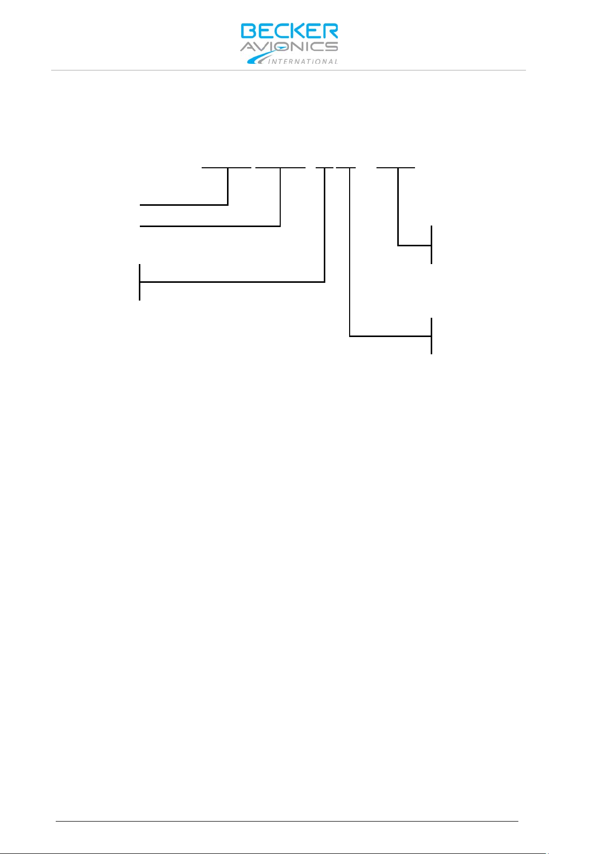
BXP
6402
-
X R - (
X X
)
Identifier
Model Number
01= Standard
XPDR Class
1= Class 1
2= Class 2
Design
Variants Overview
1.3. Variants Overview
Within the part number, the meaning of "-XR-(XX) " is:
1.3.1. Software Status
Descriptions see "Software/Firmware Status – Functionality", page 25.
Options
R= Remote Controlled
14 BXP6402 DV69802.03 Issue 04 June 2018
Page 15

Excessive pulses on the DC bus of the aircraft may cause damage on electrical
The BXP6402 is to be used inside the declared limits.
1.4. Safety-Conscious Utilization
For safe operation of the product the following notes have to be observed:
• The installation of the Mode S transponder into an aircraft may be carried
out only by an authorized installation company. The country regulations
always have to be observed.
• Use the product only within the specified conditions, see "Technical Data"
page 16.
Power supply:
• Do not connect the unit to AC sources.
• Make sure that the unit is connected to the mandatory DC source, see
"Technical Data" page 16.
• Do not connect the unit with reversed polarity to the DC source.
Circuit breaker:
• If no load is connected to connector P9, pin 6, the unit should be protected
from the aircraft power supply by a dedicated 3 A circuit breaker.
• If an external load is connected to connector P9, pin 6, the circuit breaker
should be a 5 A type.
Address module:
• The programming of the address module AM6400-1 with the ICAO 24-bit
address of the aircraft must be carried out at an installation company or in
the manufacturer factory. A programming kit is available see "Order Code"
page 21.
General Description
Safety-Conscious Utilization
circuits of any installed instrument.
Do not switch ON the device during engine start or shutdown.
1.5. Restriction for Use
DV69802.03 Issue 04 June 2018 BXP6402 15
Page 16

General Description
BXP6402
Specifications
Power supply
10...33 VDC
Typical consumption
50 Mode S replies/s + Squitter
Serial interfaces
RS422
Data link capability
255 GICB registers
DME suppression
input voltage:
< 2 V (no suppression)
output voltage
< 0.5 V (not active)
External Ident input
"0" (active) ≤ 3.5 V
Ground detection input
"ground" ≤ 0.5 V
Power-up time
2 s (including internal self-test)
Internal fuse protection
F 5 A
External fuse protection
T 3 A (circuit breaker)
Operating temperature
Class 1: -40...+55 °C (short-time +70 °C)
Storage temperature
-55...+85 °C
Operating altitude
50 000 ft. max. (class 1)
Mode S
Class 1 or 2, Level 2es
• surveillance identifier (SI code)
Technical Data
1.6. Technical Data
1.6.1. Electrical Characteristics
0.35 A at 14 V
0.20 A at 28 V
in standby Mode:
0.18 A at 14 V
0.13 A at 28 V
> 8 V (suppression)
> 18 V (active)
"1" (not active) ≥ 4.0 V
Isource (shorted to GND) ≤ 10 mA
"airborne" ≥ 2 V
Isource (shorted to GND) ≤ 10 mA
(5 A circuit breaker if an external load is connected to
P9 pin 6)
Class 2: -20...+55 °C (short-time +70 °C)
16 BXP6402 DV69802.03 Issue 04 June 2018
15 000 ft. max. (class 2)
(Class 1=250 W, Class 2=140 W at unit output)
• extended squitter capability
Page 17

BXP6402 (Transmitter Data)
Specifications
Transmit frequency
1090 MHz ± 1 MHz
Transmit modulation
12MOM1D PAM (Pulse Amplitude Modulation)
Transmitter type
Solid state
Transmit power (class 1)
≥ 125 W (+21 dBW) at antenna end terminal and
Transmit power (class 2)
≥ 70 W (+18.5 dBW) at antenna end terminal and
Reply rate capability
Mode A/C:
Mode S squitter rate (approx.)
Acquisition squitter 4/s
Reply code (mode A)
ICAO coding system with 4096 pulse reply possibilities
Altitude code (mode C)
ICAO coding system 100 ft
Altitude code (mode S)
25 ft. or 100 ft. steps
Transmit pulse shape
Pulse width 0.45 µs ± 0.1 µs (mode A/C)
Nominal output impedance
50 Ω
1.6.2. Transmitter Data
General Description
Technical Data
≥ 250 W at unit output
≥ 140 W at unit output
at least 1200 Mode A/C replies/s for a 15 pulse coded
reply, can be limited to 500...1200
Mode S:
at least 50 Mode S replies/s interval (thereof at least
16 long formats)
Extended squitter 1/s
(octal code)
steps from -1000...62700 ft.
(depending on source)
Pulse width 0.5 µs ± 0.05 µs (mode S)
Rise time 0.05...0.1 µs
Fall time 0.05...0.2 µs
DV69802.03 Issue 04 June 2018 BXP6402 17
Page 18

General Description
BXP6402 (Receiver Data)
Specifications
Operating modes
Mode A/C/S, depending on interrogation
Receive frequency
1030 MHz ± 0.1 MHz (mode A/C)
Sensitivity (MTL)
-74 dBm ± 3 dB (for 90% reply rate in mode A/C and
Selectivity
±15 MHz > 40 dB
Dynamic range
≥ 60 dB
Bandwidth
± 3 MHz < 3 dB
Modulation (mode A/C)
PAM (Pulse Amplitude Modulation)
Modulation (mode S)
DPSK (Differential Phase Shift Keying)
Side lobe suppression
3-pulse method (mode A/C),
Nominal impedance
50 Ω
Specifications
BXP6402-XR-(XX)
Front plate HxW
61x61 mm (2.4x2.4 inch)
Device depth (total)
187.7 mm (7.39 inch)
with antenna socket
186,5 mm (7.34 inch)
with address module
218.5 mm (8.6 inch)
Weight BXP6402
≤ 0.7 kg (1.54 lb)
Address module
01
approx. 0.018 kg (0.04 lb)
Technical Data
1.6.3. Receiver Data
1030 MHz ± 0.01 MHz (mode S)
99% in mode S)
±25 MHz > 60 dB
P5 (mode S)
1.6.4. Dimensions & Weight
Mounting kit MK4401
Blind encoder BE6400-
≤ 0.130 kg (0.27 lb)
approx. 0.1 kg (0.22 lb)
1.6.5. Software
The transponder BPX6402-XR-(XX) is controlled by a micro controller. The software criticality is
determined to be Level C in accordance with EUROCAE/RTCA document ED12B/DO-178B.
18 BXP6402 DV69802.03 Issue 04 June 2018
Page 19

Characteristics
Section
Cat.
Condition
Temperature and Altitude
4.0
D1
Equipment tested to Category D1
Low Ground Survival Temperature
4.5.1
D1
-55 C
Low Operating Temperature
4.5.1
D1
-20 C
High Ground Survival Temperature
4.5.2
D1
+85 C
High Short-Time Operating Temperature
4.5.2
D1
+70 C
High Operating Temperature
4.5.2
D1
+55 C
In-flight Loss of Cooling
4.5.4
Z
No auxiliary cooling required
4.6.1
D1
50 000 ft (class 1) for BXP6402-1R-(XX)
Decompression
4.6.2
X
No test performed
Overpressure
4.6.3
X
No test performed
Temperature Variation
5.0
B
5 °C minimum per minute
Humidity
6.0
A
Up to 95% humidity at 50 °C
Shock and Crash Safety
7.0
B
Equipment tested to Category B
8.0
S
Cat. S, vibration test curve M
Explosion Proofness
9.0
X
No test performed
Water Proofness
10.0
X
No test performed
Fluids Susceptibility
11.0
X
No test performed
Sand and Dust
12.0
X
No test performed
Fungus Resistance
13.0
X
No test performed
Salt Spray
14.0
X
No test performed
15.0
Z
Distance for a deflection of Dc = less
Power Input
16.0
B
Equipment tested to Category B
Voltage Spike
17.0
A
Equipment tested to Category A
Audio Freq. Conducted Susceptibility
18.0
B
Equipment tested to Category B
Induced Signal Susceptibility
19.0
A
Equipment tested to Category A
Radio Frequency Susceptibility
20.0
WW
Equipment tested to Category WW
Spurious RF Emission
21.0
B
Equipment tested to Category B
Lightning Induced Transients
22.0
A3E3X
Equipment tested to Category A3E3X
Lightning Direct Effect s
23.0
X
No test performed
Icing
24.0
X
No test performed
Electrostatic Discharge
25.0
A
Equipment tested to Category A
General Description
Technical Data
1.6.6. Environmental Condition
BXP6402-XR-(XX) was tested in accordance with EUROCAE/RTCA ED-14D/DO-160D under
consideration of below listed environmental categories and conditions:
Altitude
Vibration
Magnetic Effect
A1
15 000 ft (class 2) for BXP6402-2R-(XX)
U
Cat. U, vibration test curve G
than 0.3 m
Susceptibility
DV69802.03 Issue 04 June 2018 BXP6402 19
Page 20

General Description
Conformity
BXP6402-XR-(XX)
EASA.21O.322
ETSO-2C112a, class 1 or 2
FAA
TSO-C112, class 2A or 2B
RTCA
DO-181C
EUROCAE
ED-73B, Level 2es
Software
EUROCAE/RTCA ED12B/DO-178B Level C
In accordance with: EURO CAE/RTCA ED-14D/DO-160D
Operating altitude
50 000 ft. max. (class 1)
In-flight loss of cooling
Cat. Z, no auxiliary cooling required
Humidity
Cat. A/+50 °C; 95%, 48 h
Vibration resistance
Cat. S, test curve M
Operational shocks
6 g in any direction
Crash safety
20 g shocks
Magnetic effect
Category Z
Environmental categories
BXP6402-XR-(XX):
Technical Data
1.6.7. Certifications
15 000 ft. max. (class 2)
Cat. U, test curve G
20 g acceleration
[D1Z]BAB[(SM)(UG)]XXXXXXZBABA[WW]B[A3E3X]X
XA
20 BXP6402 DV69802.03 Issue 04 June 2018
Page 21

Qty
Mode S Transponder (remote controlled)
1 BXP6402-1R-(01), class 1
Article-No. 0588.695-915
1
BXP6402-2R-(01), class 2
Article-No. 0588.717-915
Qty
Control unit for BXP6402
1 CU6401-1-(01)
Article-No. 0572.896-915
Qty
Address module
1
AM6400-1-(01)
Article-No. 0572.942-915
Qty
Programming kit for Address module
1 AMP6400-1, parallel int erface
Article-No. 0584.843-954
1
AMP6400-2, USB interface
Article-No. 0604.054-954
Qty
Blind encoder (altitude encoder)
1 BE6400-1-(01)
Article-No. 0592.137-915
Qty
Antenna
1 1A032 Transponder antenna KEC-KC-89 (BNC)
Article-No. 0707.007-952
Qty
Mounting kit for BXP6402
1 Mounting kit MK4401
Article-No. 0556.726-284
Qty
Connector kit CK4401-S (soldering version)
Article-No. 0552.801-954
1
Connector Dsub 25-s
1 Connector housing
1 Label XPDR
Qty
Connector kit CK4401-C (crimp version)
Article-No. 0552.798-954
1
Connector Dsub 25-s
1 Connector housing
1 Label XPDR
Qty
Connector kit CK6400-S (soldering version)
Article-No. 0586.072-954
1
Connector Dsub 25-s
1 Connector Dsub 25-p
2 Connector housing
1 Label XPDR
Qty
Connector kit CK6400-C (crimp version)
Article-No. 0586.064-954
1
Connector Dsub 25-s
1 Connector Dsub 25-p
2 Connector housing
1 Label XPDR
1.7. Order Code
1.7.1. BXP6402
1.7.2. Accessories
General Description
Order Code
DV69802.03 Issue 04 June 2018 BXP6402 21
Page 22

General Description
Qty
Cable, connectors, ...
1 1K046 Cable harness, length 1 m
Article-No. 0604.615-276
1
1SK504 BNC connector for cable RG58U, soldering
Article-No. 0725.706-277
1
1SK503 TNC connector for cable RG58U, soldering
Article-No. 0725.900-277
1
TNC coaxial connector for RG-58C/U, crimp
Article-No. 0551.694-277
1
TNC coaxial connector for RG-223/U, crimp
Article-No. 0551.732-277
1
TNC coaxial connector for RG-58C/U, soldering
Article-No. 0552.781-277
1
BNC antenna connector for RG-58C/U, crimp
Article-No. 0551.708-277
1
BNC antenna connector for RG-223/U, crimp
Article-No. 0551.740-277
1
BNC antenna connector for RG-58C/U and RG-223/ U, s older ing
Article-No. 0552.771-277
Qty
Available Documentation
1 BXP6402 Installation and Operation Manual, English
Article-No. 0584.071-071
1
BXP6402 Maintenance and Repair Manual, English
Article-No. 0584.088-071
1
BXP6402-XR Control Interface Protocol
Article-No. 0590.241-071
1
BXP640X-XX-(XX) Data Transfer Interface Protocol
Article-No. 0590.258-071
Order Code
22 BXP6402 DV69802.03 Issue 04 June 2018
Page 23

Installation
Order Code
2. Installation
This manual must be available close to the device during the performance of all tasks.
Careful planning should be applied to achieve the desired per f ormance and reliability from the product.
Any deviations from the installation instructions prescribed in this document are under own
responsibility.
The BXP6402 transponder is a remote-controlled unit designed for installation in the avionic
compartment of aircraft. The installation of the BXP6402 depends on the type of aircraft and
equipment and therefore only general information can be given in this section.
In this chapter you can read about:
2.1. Packaging, Transport, Storage ................................................................................................... 24
2.1.1. Packaging Material and Transport .................................................................................... 24
2.2. Device Assignment ..................................................................................................................... 24
2.2.1. Scope of Delivery .............................................................................................................. 24
2.2.2. Additional Required Equipment ........................................................................................ 24
2.2.3. Type Plate ......................................................................................................................... 25
2.2.4. Software/Firmware Status – Functionality ........................................................................ 25
2.3. Mounting Requirements .............................................................................................................. 26
2.3.1. Order of Installation ........................................................................................................... 26
2.3.2. Blind Encoder (BE6400) ................................................................................................... 26
2.3.3. Antenna 1A032 ................................................................................................................. 26
2.4. Dimensions.................................................................................................................................. 27
2.4.1. Transponder BXP6402-XR-(XX) ....................................................................................... 27
2.4.2. Transponder BXP6402-XR-(XX) with Mounting Kit MK4401............................................ 28
2.4.3. Address Module AM6400-1-(01) ....................................................................................... 29
2.4.4. Blind Encoder BE6400 ...................................................................................................... 29
2.4.5. Antenna 1A032 ................................................................................................................. 30
2.5. Electrical Installation ................................................................................................................... 31
2.5.1. Grounding ......................................................................................................................... 31
2.5.2. BXP6402 Connector Layout ............................................................................................. 32
2.5.3. Connector J6 ..................................................................................................................... 32
2.5.4. Connector P9 (Dsub 25-pol male) .................................................................................... 32
2.5.5. Connector J8 (Dsub 25-pol female) .................................................................................. 33
2.5.6. Connector J7 (5-pol female) ............................................................................................. 35
2.5.7. External Suppression ........................................................................................................ 35
2.5.8. External IDENT Push-Button ............................................................................................ 35
2.5.9. Ground Switch .................................................................................................................. 35
2.5.10. Programming of the Address Module ............................................................................... 36
2.5.11. Avionics Data Transfer...................................................................................................... 36
2.5.12. GPS Configuration ............................................................................................................ 37
2.5.13. Remote Control ................................................................................................................. 38
2.6. Settings after Installation ............................................................................................................. 39
2.7. Warning and Failure Indications ................................................................................................. 40
2.8. Aircraft Wiring .............................................................................................................................. 40
2.8.1. BXP6402 with Parallel Encoding Altimeter & GPS Receiver............................................ 41
2.8.2. BXP6402 with Serial Encoding Altimeter & GPS Receiver .............................................. 42
2.8.3. BXP6402 with Serial Encoding Altimeter (Cutout) ............................................................ 43
2.8.4. BXP6402 with RS232 GPS Receiver (Cutout) ................................................................. 43
2.9. Check after Installation ................................................................................................................ 44
2.9.1. Pre-Flight Check Using Self Test ...................................................................................... 44
2.9.2. Check of the Address Module ........................................................................................... 44
2.9.3. Test and Adjustment of Transmit Frequency .................................................................... 44
2.9.4. Check of Transmit Power ................................................................................................. 44
DV69802.03 Issue 04 June 2018 BXP6402 23
Page 24

Installation
The packaging material is inf lamm able, if it is dispose d of im properl y by burni ng,
Do not use products with damages!
Packaging, Transport, Storage
2.1. Packaging, Transport, Storage
Visually inspect the package contents for signs of transport damage.
2.1.1. Packaging Material and Transport
The packaging materia l can be kept and reused in the cas e of a return shipment. Improper or f aulty
packaging may lead to transport damages.
Make sure to transport the device always in a safe manner and with the aid of suitable lifting
equipment if necess ary. Do nev er use th e elec tric c onnect ions f or lifting. Befor e the tr anspor t, a cl ean,
level surface should be prepared to place the device on. The electric connections may not be
damaged when placing the device.
First Device Checkup
• Check the device for signs of transport damages.
• Please verify if the indications on the type plate correspond to your purchase order.
• Check if the equipment is complete ("Scope of Delivery", page 24).
toxic fumes may develop.
Storage
If you do not wish to mount and insta ll the de vice im medi atel y, mak e sure to stor e it in a dr y and clean
environment. Make sure that the device is not stored near strong heat sources and that no metal
chippings can get into the device.
2.2. Device Assignment
This manual is valid for the following devices:
• BXP6402-1R-(01) + supplement
2.2.1. Scope of Delivery
2.2.2. Additional Required Equipment
Details see "Accessories", page 21.
• BXP6402-2R-(01) + supplement
• Manuals
o Operating Instructions
• Transponder
o BXP6402 (corresponding t o your ord ered ver sio n)
• Documents of Certifications if available
• Address module AM6400-1-(01) programmed
• Mounting kit
o MK4401
• Connector kit
• Antenna
• Antenna cable
• CU6401 control unit or OEM control unit
24 BXP6402 DV69802.03 Issue 04 June 2018
Page 25

PN:
Example Type designation: BXP6402-1R-(01)
SN:
Unique number of the particular device
AN:
Article number
Software
Compliance and Certifications
Software/Firmware Status
Functionality
CU VER 2x
CU VER 2x
2.2.3. Type Plate
The device type is defined by the type plate (on the housing):
Example:
Figure 1: Type Plate (example)
Explanation:
BXP6402 = Transponder, BXP640X family
Installation
Device Assignment
Options:
-1R-: class 1, remote controlled
-2R-: class 2, remote controlled
(01): standard
Corresponding to the displayed version
Corresponding to the displayed text and logos
2.2.4. Software/Firmware Status – Functionality
The implemented firmware version can be checked with the control unit:
• With control unit CU6401 please see in the "Operating with CU6401 Contro ller ", p age 45.
• With other control unit please see in corresponding user manual.
Units equipped with non-ADS B out capable software can be modified from our Customer Service
Department..
CORE VER 42
FPGA VER 50
CORE VER 47
DV69802.03 Issue 04 June 2018 BXP6402 25
FPGA VER 55
no ADS-B out
ADS-B out
not certified according to TSO-C166b; only
capable for GA Traffic Receiver e.g. FLARM(R)
Page 26

Installation
The device must not be opened.
The installation of the Mode S transponder into an aircraft may be carried out only
The transponder antenna 1A032 is provided with a silicone rubber gasket which
Mounting Requirements
2.3. Mounting Requirements
When installing the device, make sure the heat dissipators of the device receive
sufficient air. Keep an efficient distance of the devices with integrated venti lat or
fans in order to ensure free circulation of the cooling air.
Make sure that the mounting plate is not exposed to external temperature
influences.
The mounting place shall be at least 30 cm from the magnetic aircraft compass, to
avoid any interference to the magnetic compass by the transponder.
2.3.1. Order of Installation
• Installation with MK4401 (mounting kit), first install the mounting frame using three
countersunk screws.
• Loosen the securing-plate from mounting frame.
• Slide the transponder into the mounting.
• Push the security-plate into the locking slot and tighten the securing-plate.
• Carry out removal of the transponder in reversed order.
by an authorized installation company. The country regulations always have to be
observed.
2.3.2. Blind Encoder (BE6400)
For installation of the Becker Avionics Blind Encoder BE6400 the corresponding manual has to be
noticed (BE6400 I&O manual Article-No. 0594.547-071).
• The Blind Encoder BE6400 is intended to be connected to connector J8 of the
transponder.
• The Blind Encoder is direct connected without any interwiring.
• It can be used only in installations that do not require connection of other equipment
utilizing ADLP interface of the transponder.
2.3.3. Antenna 1A032
• Fit the transponder antenna to the bottom of the aircraft at a horizontal, flat location.
o This location should not be in the "shadow" of aircraft structure items.
o The highest range is achieved when the antenna is located at the lo west po int of
the aircraft fuselage.
must also be interposed between the skin of the aircraft and the antenna.
In aircraft having a wooden or plastic airframe an electric counterweight plate or
panel must be located within the fuselage at the antenna location with minimum
dimensions 400x400 mm (15.7x15.7 inch).
2.3.3.1. Antenna Cable
• Cable types RG-58C/U (0.9 dB/m) or RG-223/U (0.6 dB/m) can be used.
o With cable length >2 m between unit and antenna, we recommended cable type
RG-223/U.
• Recommended cable length ≤5 m.
• Complete loss of the antenna cable ≤3 dB.
26 BXP6402 DV69802.03 Issue 04 June 2018
Page 27

Allowable deviation for dimensions without tolerances: DIN ISO 2768 T1 C
xx...6 (±0.3)
>30...120 (±0.8)
>400...1000 (±2.0)
>6...30 (±0.5)
>120...400 (±1.2)
>1000...2000 (±3.0)
CENTER OF GRAVITY
1
61 (2.4 in)
3.4 (0.13 in)
169.8 (6.68 in)
76.8 (3.02 in)
45.3 (1.78 in)
14.5 (0.57 in)
13.3 (0.52 in)
30.65
(1.21 in)
30.5
(1.2 in)
61
(2.4 in)
J8
P9
J7
J6
1
14 25
13
13
25
14
1
2.4. Dimensions
2.4.1. Transponder BXP6402-XR-(XX)
Installation
Dimensions
Dimensions mm (in ch)
access to TX frequency adjustment
Figure 2: Transponder BXP6402-XR-(XX)
DV69802.03 Issue 04 June 2018 BXP6402 27
"Center of Gravity" without address module.
Page 28

Installation
Allowable deviation for dimensions without tolerances: DIN ISO 2768 T1 C
xx...6 (±0.3)
>30...120 (±0.8)
>400...1000 (±2.0)
>6...30 (±0.5)
>120...400 (±1.2)
>1000...2000 (±3.0)
CENTER OF GR AVITY
236 (9.29 in)
8 (0.31 in)
45 (1.77 in)
8.1 (0.32 in)
218.5 (8.60 in)
32.5
(1.28 in)
32.5
(1.28 in)
50 (1.97 in)
65 (2.56 in)
71.1 (2.8 in)
40.5
(1.59 in)
128 (5.04 in)
Ø5
(Ø0.19 in)
Ø10
(Ø0.39 in)
A
A
Dimensions
2.4.2. Transponder BXP6402-XR-(XX) with Mounting Kit MK4401
Dimensions mm (in ch)
"Center of Gravity" without address module.
28 BXP6402 DV69802.03 Issue 04 June 2018
Figure 3: Mounting Kit MK4401
Page 29

46.4 (1.83 in)
Ø4
(0.16 in)
Ø14
(0.55 in)
3
(0.12 in)
2.4.3. Address Module AM6400-1-(01)
Figure 4: Address Module AM6400-1-(01)
Installation
Dimensions
Dimensions mm (in ch)
2.4.4. Blind Encoder BE6400
Dimensions mm (in ch)
Figure 5: Blind Encoder BE6400
DV69802.03 Issue 04 June 2018 BXP6402 29
Page 30

Installation
Dimensions
2.4.5. Antenna 1A032
Dimensions mm (in ch)
30 BXP6402 DV69802.03 Issue 04 June 2018
Figure 6: Antenna 1A032
Page 31

Radiation risk:
Make sure that the grounding contact area is adequate and that the connection
2.5. Electrical Installat i on
• The installation of the Mode S transponder into an aircraft may be carried out
only by an authorized installation company. The country regulations always
have to be observed.
Power supply:
• Do not connect the unit to AC sources.
• Make sure that the unit is connected to the mandatory DC source, see
"Technical Data" page 16.
• Do not connect the unit with reversed polarity to the DC source.
Circuit breaker:
• If no load is connected to connector P9, pin 6, or if the unit is used with the
retrofit adapter, the unit should be protected from the aircraft power supply by
a dedicated 3 A circuit breaker.
• If an external load is connected to connector P9, pin 6, the circuit breaker
should be a 5 A type.
Address module:
• The programming of the address module AM6400-1 with the ICAO 24-bit
address of the aircraft must be carried out only at an installation company or
in the manufacturer factory.
For installations in a more severe electromagnetically environment use shielded
cable connectors and a common shielding for the transponder inter wiri ng.
Installation
Electrical Installation
A safe distance to the installed antenna must be ensured by corresponding
installation measures around human body damage (e.g. at the eyes) and/or avoid
the inflammation of combustible materials by radiated energy.
2.5.1. Grounding
The transponder has a thr e aded groun di ng b olt at the rear side of the unit. Use this point as grounding
contact.
has low resistance and low inductance. Never use a grounding point on paintcoated surfaces!
DV69802.03 Issue 04 June 2018 BXP6402 31
Page 32

Installation
P9
Pin name
Function
Source
Destination
Recommended
1
A1
Altitude A1
encoding altimeter
BXP6402
AWG24
2*
A2
Altitude A2
encoding altimeter
BXP6402
AWG24
GPS /Enable
aircraft DC supply
AWG26
3
A4
Altitude A4
encoding altimeter
BXP6402
AWG24
4
IDENT_N
IDENT button,
external IDENT
BXP6402
AWG26
5
EXT.
Aircraft suppression
bi-directional
bi-directional
Coaxial cable
6
SWITCHED
Switched supply
BXP6402
encoding
AWG22
7
REPLY OUT
Output for ext. reply
connected to positive
BXP6402
reply lamp
AWG26
8
RX+
RS422 interface
CU6401
BXP6402
AWG26 shielded
9
RX-
RS422 interface
CU6401
BXP6402
AWG26 shielded
11
SUPP
Supply voltage input,
DC supply voltage
BXP6402
AWG20
J8
P9
J7
J6
1
14
25
13
13
2514
1
Electrical Installation
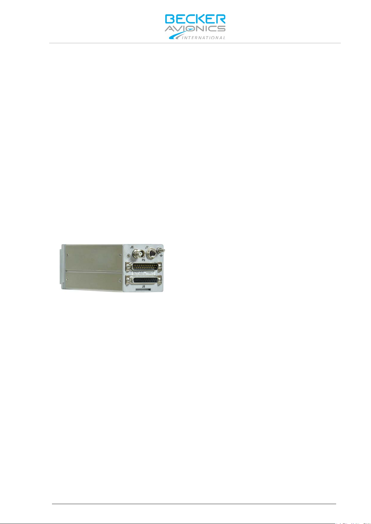
2.5.2. BXP6402 Connector Layout
Figure 7: BXP6402 Connector Layout
2.5.3. Connector J6
Antenna RF connector (from transponder via cable to antenna).
• Type: TNC female.
• Antenna cable: low-loss 50 Ω cable, RG 58C/U or RG 223/U type.
• Signal: bi-directional
J6: Antenna
J7: Address module
2.5.4. Connector P9 (Dsub 25-pol male)
Pin
or
external
SUPPRESSION
POWER OUT
system
voltage Imax = 1 A
lamp, lamp to be
illumination voltage
cable type
(parallel interface)
(parallel interface)
ground*
(parallel interface)
button
altimeter
32 BXP6402 DV69802.03 Issue 04 June 2018
external 5 A fuse for
source 10...33 V
Page 33

P9
Pin name
Function
Source
Destination
Recommended
current protection
12
SUPP
Supply voltage input,
DC supply voltage
BXP6402
AWG20
13
GND
DC supply ground,
DC supply voltage
BXP6402
AWG20
14
B1
Altitude B1
Encoding altimeter
BXP6402
AWG24
15
B2
Altitude B2
Encoding altimeter
BXP6402
AWG24
16
B4
Altitude B4
Encoding altimeter
BXP6402
AWG24
17
C1
Altitude C1
Encoding altimeter
BXP6402
AWG24
18
C2
Altitude C2
Encoding altimeter
BXP6402
AWG24
19
C4
Altitude C4
Encoding altimeter
BXP6402
AWG24
20
D4
Altitude D4
Encoding altimeter
BXP6402
AWG24
21
TX+
RS422 interface
BXP6402
CU6401
AWG26
22
TX-
RS422 interface
BXP6402
CU6401
AWG26
24
ON_N
ON/OFF signal
CU6401
BXP6402
AWG26
25
GND
Ground, additionally
DC supply voltage
BXP6402
AWG20
Note P9:
*If no parallel altimeter is used then pin2 serves as GPS Enable/Disable input (active LOW). If no GPS receiver is
J8
Pin name
Function
Source
Destination
Recommended
1
PSEL
Protocol selection
DC supply voltage
BXP6402
AWG26
2*
GPS_EN
GPS /Enable
Aircraft DC supply
BXP6402
AWG26
3
GND
Ground connection
Aircraft DC supply
BXP6402
AWG24
41)
BSUPP
Supply for BE6400
BXP6402
BE6400
-
5
Not connected
-
- - -
6
RX+
GPS receiver
GPS receiver
BXP6402
AWG26 shielded
Electrical Installation
Installation
Pin
external 5 A fuse for
current protection
additionally
connected to Pin25
cable type
source 10...33 V
ground
(parallel interface)
(parallel interface)
(parallel interface)
(parallel interface)
(parallel interface)
(parallel interface)
connected to Pin13
used Pin2 should be left not connected.
For details see "Aircraft Wiring", page 40.
2.5.5. Connector J8 (Dsub 25-pol female)
Pin
(parallel interface)
ground
cable type
ground
ground
ground
DV69802.03 Issue 04 June 2018 BXP6402 33
Page 34

Installation
J8
Pin name
Function
Source
Destination
Recommended
7
RX-
GPS receiver
GPS receiver
BXP6402
AWG26 shielded
8
Not connected
-
- - -
9
Not connected
-
- - -
10
Not connected
Reserved for SQ
- - -
11
GND SWITCH
"Weigth on wheel"
Aircraft
BXP6402
AWG26
122)
ALTS-
RS422 data interface
Serial encoding
BXP6402
AWG26 shielded
132)
ALTS+
RS422 data interface
Serial encoding
BXP6402
AWG26 shielded
14
TISRX-
RS422 data interface
Avionics Data Link
BXP6402
AWG26 twisted
15
TISRX+
RS422 data interface
Avionics Data Link
BXP6402
AWG26 twisted
16
Not connected
-
- - -
17
TISTX-
RS422 data interface
BXP6402
Avionics
AWG26 twisted
18
TISTX+
RS422 data interface
BXP6402
Avionics
AWG26 twisted
19
Not connected
-
- - -
20
Not connected
-
- - -
21
GND
ground connection
Aircraft DC supply
BXP6402
AWG24
22
Not connected
-
- - -
23
Not connected
-
- - -
24
Not connected
-
- - -
25
Not connected
-
- - -
Note J8:
Electrical Installation
Pin
sensor, active LOW
altimeter
altimeter
Processor
Processor
Data Link
Processor
cable type
pair, shielded all
together
pair, shielded all
together
pair, shielded all
together
ground
1) Do not connect if no BE6400 is used.
2) Serial encoding altimeter connection (not for BE6400).
*If no GPS receiver is used then Pin2 should be left not connected.
For details see "Aircraft Wiring", page 40.
Data Link
Processor
pair, shielded all
together
34 BXP6402 DV69802.03 Issue 04 June 2018
Page 35

J7 Pin
Pin name
Function
Source
Destination
1
VCC
Power supply
BXP6402
AM6400
2
I2C_CLK
Clock
AM6400
BXP6402
3
Not connected
Reserved
-
-
4
I2C_DAT
Data
AM6400
BXP6402
5
GND
Power supply return
BXP6402
AM6400
2.5.6. Connector J7 (5-pol female)
Electrical Installation
Installation
2.5.7. External Suppression
External suppression s hould be connected if another tr ansponder or DME is installed in t he aircraft.
The suppression pulses may not be compatible with all models of DME. In this case, leave the
suppression pin open (e.g. P9 pin 5).
In cases when the DME has onl y a suppression output ( e.g. Bendix/King KN62, KN64 and KNS80)
inserted a diode in the suppression line. Details see "Aircraft Wiring" page 40.
2.5.8. External IDENT Push-Button
If this input (unit c onn ector P9 pin 4) is br ief ly connected to GND (e. g. by an external push-button), the
IDENT function (SPI ) is started in the sam e way as when using the ID ENT push-button on the f ront
panel.
2.5.9. Ground Switch
• If required, connect an automatic ground switch ("Weight on Wheel" sensor) at unit
connector J8 pin 11.
DV69802.03 Issue 04 June 2018 BXP6402 35
Page 36

Installation
Electrical Installation
2.5.10. Programming of the Address Module
The 24-bit ICAO address once allocated b y the local authority is stored f or the assigned tr ansponder
in the Address Module AM6400.
The address module pr ogrammer kit AMP6400 is for reading a nd storing fixed aircraft data into th e
Address Module. This to ol is for service and maintenance only. The CD-ROM, which is part of the
address module programmer kit, includes a description of the programming procedure. Insert the
CD-ROM into a PC and follow the instructions. If auto start is disabled on your PC, please start
"setup.exe" manually.
2.5.11. Avionics Data Transfer
• The BXP6402 is a "data link transponder" according to RTCA DO-181C, respectively a
"level 2" transpo nder ac c ordin g to Eurocae ED-73B.This stands for the capability to
transfer data from the ground to a connected ADLP or a similar device and vice versa.
• The transponder transmits information as reply on a Ground Initiated Comm-B (GICB)
request or by means of the extended squitter function. In both cases the valid information
must be available in the GICB registers in the transponder.
• The transponder also transmits information by means of the Air Initiated Comm-B (AICB)
function. In this case the information must be available in a special register in the
transponder. The transponder announces the message and transmits it after authorisation
from the ground station.
• In the other direction, the transponder is able to receive information within a Comm-A
format from the ground station, which is then buffered and transfer red to the connected
device.
• In the BXP6402 a "storage design" is implemented for uplink- as well as for downlink
messages. This means that all information that might be transferred from the transponder
is buffered inside the transponder first.
• The buffers can be accessed from an ADLP or a similar device via the interface on the
rear connector J8. The interface is marked with "TISRX" and "TISTX" in the aircraft wiring
diagram (see page 40).
• The related protocol is specified in the attachment document "Data Transfer Interface
Protocol BXP640X-XX-(XX)". This manual is available at the Becker Product Support
under Article-No. 0590.258-071.
36 BXP6402 DV69802.03 Issue 04 June 2018
Page 37

FreeFlight 1201
NexNav
NMEA
Baud Rate:
19200 bps
19200 bps
4800 bps
#Data Bits: 8 8
8
Parity:
none
none
none
Stop Bits: 1 1
1
Code:
binary
binary
ASCII
Electrical Installation
Installation
2.5.12. GPS Configuration
• If a GPS receiver is used, connect “GPS_EN” to DC supply ground.
o BXP6402 “GPS_EN” J8 pin2 DC supply ground.
• GPS receiver data line connection to BXP6402 see:
o “BXP6402 with Parallel Encoding Altimeter & GPS Receiver” page 41.
o “BXP6402 with Serial Encoding Altimeter & GPS Receiver” page 42.
• GPS receiver supply connection to BXP6402:
BXP6402 “SWITCHED POWER OUT” P9 pin6* ≙ supply voltage P9 p in 11, 12.
(if its current consumption ≤1 A, otherwise it should be connected directly to aircraft
supply).
*when the BXP640X is switched ON the output voltage P9 pin6 corresponds to the supply voltage (P9 pin11, 12).
The equipment is capable to operate with following certified GPS receivers:
• FreeFlight System GPS/WAAS 1201 Sensor, part number 84100-02-XXXX
• NexNav miniGNSS/ GPS-SBAS Sensor/ Receiver.
The equipment is capable to operate with GPS receivers providing EIA-232C or EIA-422 interface with
serial asynchronous transmission parameters: 4800, n, 8, 1 and transmit data with continuous
NMEA-0183 protocol GGA and VTG sentences.
2.5.12.1. GPS Device Protocols
Electrical format – RS232 with the following characteristics:
DV69802.03 Issue 04 June 2018 BXP6402 37
Page 38

Installation
Electrical Installation
2.5.13. Remote Control
• BXP6402 is a remote-controlled transponder and needs an additional controlling device.
o Use the control unit CU6401 from Becker Avionics; a special designed control unit,
which offers the complete set of control functions and indications.
o Use another device (e.g. FMS).
• Two interfaces are available for that purpose.
o "RX", "TX" on connector P9 of the transponder.
The transponder accepts and transmits only control messages via this interface.
o "TISRX", "TISTX" on connector J8 of the transponder.
A combined interface which handles control and data transfer in parallel.
The protocol for both interfaces is described in the document: "BXP6400 Extended Protocol".
This document is available at the Becker Product Support.
38 BXP6402 DV69802.03 Issue 04 June 2018
Page 39

Select with button
Select with rotary encoder
Store button (STO)
ALTM SELECT
GARMIN / TRIMBLE
store
PARALLEL
default
store
DIMMING INPUT
None
default
store
+5 VDC
store
SQUITTER
Short ACQ SQU *
default on
off/on
REPLY RATE LIMIT
RPL RATE LMT
store
SPECIALS
DATA LINK **
store
Error Latch
LOW VOLT
view only
Settings after Installation
Installation
2.6. Settings after Installation
Following description is valid for the BXP6402 remote transponder with the control unit CU6401.
With another contr ol unit the control pr otocol se ttings must be car ried out as they are des cribed in the
document "Control Interface Protocol BXP6402-XR" see ”Order Code”, page 21.
Installation mode is available from SBY mode only.
• Press button SEL,
• Turn the rotary encoder until "INS" appears in the bottom line of the display.
• Select by pressing rotary encoder/push-button.
The installation setup is protected by password "6435".
• Enter password and press store button (STO).
Information front panel see "Operat i ng with CU6401 Cont rol l er", page 45
NORTHSTAR
UPS AT (BECKER BE6400)
UPS AT LORAN
MAGELLAN
SHADIN
ARNAV
(set illumination intensity manually in
the configuration menu)
+14 VDC
+28 VDC
500-1200 replies/s in Mode A/C (setting
in steps of 50)
DEFAULT CONFIG ***
ALT HIGH RESOL
store
store
store
store
store
store
store
store
store
store
*Transponders equ ipped for extended squitter operation should have a means to disab le acquisition
squitters to fac ilitate the s u ppr ess ion of ac quisit ion s q uitt ers when a ll T C AS units have been converted
to receive extended squitter.
DV69802.03 Issue 04 June 2018 BXP6402 39
HIGH TEMP
ANTENNA
RF POWER
DME ERR
SQRT ERR
CORE EE
RECEIVER
FIX DATA
ALTIMETER
DATA LINK
Clear latch
view only
view only
view only
view only
view only
view only
view only
view only
view only
view only
clear latch
Page 40

Installation
*** Default configuration:
Dimming input
none
Brightness
50%
Altitude displayed in ALT mode
AI in SBY
AI in ON
IIlumination characteristics
max. range
Code
0000
VFR
0000
Flight number
eight blanks
Flight number
not active
Installation of the unit varies according to aircraft and equipment design. It
Warning and Failure Indications
**Shall be disabled if no ADLP or similar device is connected.
2.7. Warning and Failure Indications
It is possible to read out t he error latches. If m ultiple failures are listed pleas e keep in your mind the
listed failures and delete the latches with the "Clear Latch" store sequence.
2.8. Aircraft Wiring
is therefore only possible to provide general guidelines in this section.
The following figures show exam ples of airc raft wiring with BXP 64 02. F or f ur ther i nf orm at ion of aircraft
wiring with other devices refer to the corresponding manuals.
Wiring diagram with CU6401
For detailed information refer to the manual CU6401 Installation and Operation DV69803.03
(Article No. 0584.096-071).
Wiring diagram with OEM Controller
For detailed information refer to the manual of the respective OEM product.
40 BXP6402 DV69802.03 Issue 04 June 2018
Page 41

11
12
**5
2xAWG26 shielded, twisted
2xAWG26 shielded, twisted
AWG26 shielded
2xAWG20
AWG26
AWG22
AWG26
2xAWG26 shielded, twisted
2xAWG26 shielded, twisted
2xAWG26 shielded, twisted
7
4
13
25
AWG26
AWG26
****
+10...33 VDC supply
11
14
15
17
18
3
21
Aircraft suppression
system
+10...33 VDC
supply
3 A (5 A if ext. load is connected to P9 pin6)
Control unit
CU6401
IDENT***
REPLY
„Weight on wheel” sensor
Coaxial cable RG58C/U or RG223/U 50 Ω
Antenna
11
12
5
7
4
13
25
11
14
15
17
18
3
21
RF
SUPP
SUPP
EXT.
SUPPR.
REPLY
6 ## 6
##
SWITCHED
POWER OUT
IDENT_N
GND
GND
SWITCH
GND
TISRXTISRX+
TISTXTISTX+
11
PSEL
GND
GND
BXP6402
grounding screw
AWG16
Address ModuleAM6400
P9
J8
J6
J7
connection to shell
connection to shell
2xAWG20
6
7
TX+
Supply (+)
TX-
GND
GPS receiver
6
7
RX+
*22
GPS_EN
RX-
8
9
8
9
RX+
2424
ON_N
RX-
21
22
21
22
TX+
TX-
1
2
3
14
15
16
17
18
19
20
10xAWG24
Parallel encoding
altimeter
#
GND
A1
A2
A4
B1
B2
B4
C1
C2
C4
D4
1
2
3
14
15
16
17
18
19
20
GND
ON_N
TX+
TX-
RX+
RX-
3
13
1
2
4
5
TXTX+
RXRX+
GND
Avionics Data
Link Processor
****
Note:
* Don´t connect J8 pin2 if no GPS receiver is used.
** P9 pin5 is EXT. SUPPR. input and output of the unit. If a
DME is used, which is not bi-directional, a diode (1N4001 or
equivalent) must be inserted in the EXT. SUPPR. line
*** External IDENT button can be connected to the Remote Unit
or the Control Unit.
**** Must be connected, when BXP6402 is controlled byADLP
(no CU6401).
# Select serial or parallel type of encoding altimeter.
## P9 pin6 output ≙ supply voltage P9 pin11,12.
2.8.1. BXP6402 with Parallel Encoding Altimeter & GPS Receiver
Installation
Aircraft Wiring
DV69802.03 Issue 04 June 2018 BXP6402 41
Figure 8: BXP6402 with Parallel Encoding Altimeter & GPS Receiver
Page 42

Installation
11
12
**5
2xAWG26 shielded, twisted
2xA
WG26 shielded, twisted
AWG26 shielded
2x
AWG20
AWG26
AWG26
2xA
WG26 shielded, twisted
2xAWG26 shielded, twisted
2xAWG26 shielded, twisted
2xAWG26 shielded, twisted
7
4
13
25
AWG26
AWG26
****
+10...33 VDC supply
11
14
15
17
18
3
21
Aircraft suppression
system
+10...33 VDC
supply
3
A (5 A if ext. load is connected to P9 pin6)
IDENT***
REP
LY
„Weight on wheel” sensor
Coaxial cable RG58C/U or RG223/U 50 Ω
Antenna
11
12
5
7
4
13
25
11
14
15
17
18
3
21
RF
SUPP
SUPP
EXT.
SUPPR.
REPLY
IDENT_N
GND
GND
SWITCH
GND
TISRXTISRX+
TISTXTISTX+
11
PSEL
GND
GND
BXP6402
grounding screw
AWG16
Address ModuleAM6400
P9
J8
J6
J7
connection to shell
connection to shell
2x
AWG20
12
13
TXTX+
GND
12
13
AL
TS-
ALTS+
8
9
8
9
RX+
24
24
ON_N
RX-
21
22
21
22
TX+
TX-
10x
AWG24
TXTX+
RXRX+
GND
Avionics Data
Link Processor
****
Note:
* Don´t connect J8 pin2 if no GPS receiver is used.
** P9 pin5 is EXT. SUPPR. input and output of the unit. If a
DME is used, which is not bi-directional, a diode (1N4001 or
equivalent) must be inserted in the EXT. SUPPR. line
*** External IDENT button can be connected to the Remote Unit
or the Control Unit.
**** M ust be connected, when BXP6402 is controlled byADLP
(no CU6401).
# Select serial or parallel type of encoding altimeter.
## P9 pin6 output ≙ supply voltage P9 pin11,12.
Serial encoding
altimeter
#
AWG22
6
## 6
##
SWITCHED
POWER OUT
6
7
TX+
Supply (+)
TXGND
GPS receiver
6
7
RX+
*2
2
GPS_EN
RX-
Control unit
CU6401
GND
ON_N
TX+
TX-
RX+
RX-
3
13
1
2
4
5
Aircraft Wiring
2.8.2. BXP6402 with Serial Encoding Altimeter & GPS Receiver
Figure 9: BXP6402 with Serial Encoding Altimeter & GPS Receiver
42 BXP6402 DV69802.03 Issue 04 June 2018
Page 43

If the blind encoder BE6400 is directly connected to J8 it is not possible to
P9
J8
TX
GND
Serial encoding
altimeter
12
13
21
ALTS-
ALTS+
GND
BXP640X
P9
J8
TX
GND
GPS receiver
6
7
2
21
RX+
RX-
GPS_EN
GND
BXP6402
2.8.3. BXP6402 with Serial Encoding Altimeter (Cutout)
Figure 10: BXP6402 - Serial Encoding Altimeter Connection (not for BE6400)
2.8.4. BXP6402 with RS232 GPS Receiver (Cutout)
Installation
Aircraft Wiring
Figure 11: BXP6402 - RS232 GPS Receiver Conn ec ti on (not with BE6 40 0)
connect a GPS receiver for ADSB-out function to J8.
DV69802.03 Issue 04 June 2018 BXP6402 43
Page 44

Installation
After the installation, check the transponder to ensure satisfactory
Radiation risk:
Check after Installation
2.9. Check after Installation
operation of the unit.
This should be done on the ground. Generally, this should not be used
during flight.
2.9.1. Pre-Flight Check Using Self-Test
2.9.1.1. Switch-on test:
• Switch the transponder operating mode switch from OFF to SBY.
• If the test was successful, the unit switches then to the mode set on the mode switch.
2.9.1.2. Test triggered (IBIT):
• Press the SEL button and STO button at the same time in mode ON or ALT.
• If the IBIT was successful, the transponder switches immediately into the normal operating
mode.
• In case of a fault appears the report "FAILURE" in the display.
• Switch OFF the transponder at the fault indication.
o A power-on built-in test (PBIT) then follows automatically for 1 second.
o During the test "WAIT is indicated.
o A test of all available test routines then follows for 1 second.
o During the test, "IBIT" is indicated on the display.
2.9.2. Check of the Address Module
The installation company has to make sure that the corresponding address module AM6400 is
installed with the transponder and that the address module is programmed correctly. Connect the
address module with the aircraft tightly.
2.9.3. Test and Adjustment of Transmit Frequency
• Set code 0000 on the transponder and mode A interrogation on the ramp test set.
• Check transmit frequency by means of the ramp test set.
• Transmit frequency must be 1090 ± 1 MHz.
o If out of range send the transponder to authorized service.
2.9.4. Check of Transmit Power
After installation of equipment and antenna the transm it power has to be check ed at the antenna end
of the feeder line. Requirement:
≥ 125 W (21 dBW) at class 1 transponder.
≥ 70 W (18.5 dBW) at class 2 transponder.
A safe distance to the installed antenna must be ensured by corresponding
installation measures around human body damage (e.g. at the eyes) and/or avoid
the inflammation of combustible materials by radiated energy.
44 BXP6402 DV69802.03 Issue 04 June 2018
Page 45

Operating Instructions
Device Description
3. Operating Instructions
In this chapter you can read about:
3.1. Device Description ...................................................................................................................... 45
3.1.1. Device Assignment ........................................................................................................... 45
3.1.2. Packing, Transport, Storage ............................................................................................. 45
3.1.3. Scope of Delivery .............................................................................................................. 45
3.1.4. Type Plate ......................................................................................................................... 45
3.2. Operating with CU6401 Control ler .............................................................................................. 45
3.3. Operating with OEM Controller ................................................................................................... 45
3.1. Device Description
The BXP6402 is intended for installation in an aircraft. It works in accordance with the secondary radar
principle and allows air traffic control to locate, identify and track aircraft.
BXP6402 is a rem ote-controlled transponder and ne eds an additional controllin g device. For further
information about Interface and protocol refer to the document "BXP6400 Extended Protocol" available
at the Becker Product Support.
3.1.1. Device Assignment
This manual is valid for the following devices:
• See page 24
3.1.2. Packing, Transport, Storage
• See page 24
3.1.3. Scope of Delivery
• See page 24
3.1.4. Type Plate
• See page 25
3.2. Operating with CU6401 Controller
For detailed information refer to the manual CU6401 Installation and Operation DV69803.03
(Article No. 0584.096-071).
3.3. Operating with OEM Controller
For detailed information refer to the manual of the respective OEM product.
DV69802.03 Issue 04 June 2018 BXP6402 45
Page 46

Operating Instructions
Operating with OEM Controller
Blank Page
46 BXP6402 DV69802.03 Issue 04 June 2018
Page 47

Operating Instructions
Operating with OEM Controller
Blank Page
DV69802.03 Issue 04 June 2018 BXP6402 47
Page 48

Index
4. Index
Accessories .................................................. 21
Additional Required Equipment .................... 24
Conditions of Utilization ................................ 10
Connector J6 ................................................ 32
Connector J7 ................................................ 35
Connector J8 ................................................ 33
Connector P9 ................................................ 32
Device Assignment ................................. 24, 45
Dimensions ................................................... 27
Electrical Installation ..................................... 31
Environmental Condition............................... 19
General Description ...................................... 11
Grounding ..................................................... 31
Installation ..................................................... 23
We reserve the right to make technical changes.
The data correspond to the current status at the time of printing.
© by Becker Avionics GmbH / all rights reserved
*** End of the Document ***
List of Abbreviat ions ........................................ 7
Mounting ....................................................... 26
Non-Warranty Clause ................................... 10
Operation Instructions ................................... 45
Packaging, transport, storage ....................... 24
Purpose of Equipment .................................. 13
Safety Definitions ............................................ 9
Type Plate ..................................................... 25
Units ................................................................ 9
Variants Overview ......................................... 14
Warning and Failure Indications ................... 40
Warranty Conditions ..................................... 10
Wiring Diagrams............................................ 41
48 BXP6402 DV69802.03 Issue 04 June 2018
 Loading...