

Page 1
Courtesy of:DiscountCarStereo.com
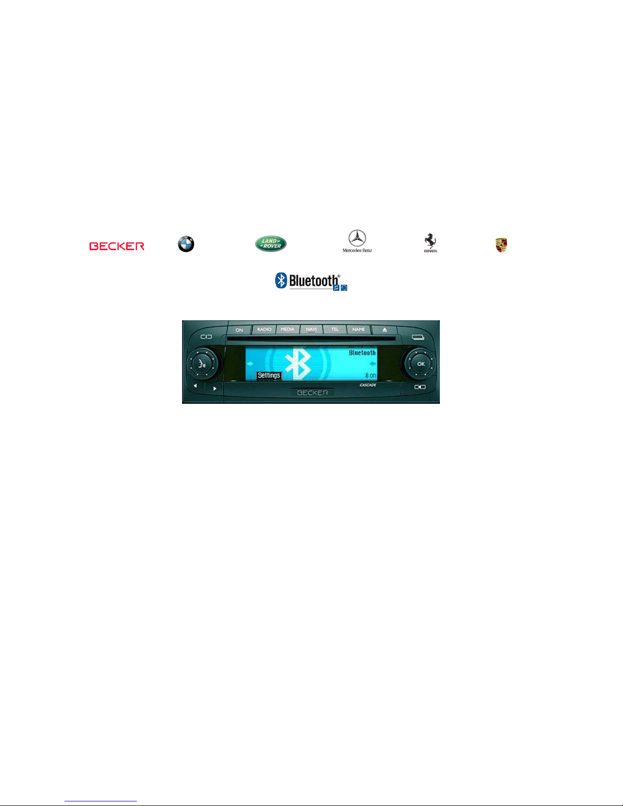
Radio shown for illustration purposes only
BT45-BKR
Quick Install Guide for
Quick Install Guide for Quick Install Guide for
Quick Install Guide for
Becker
Becker Becker
Becker Aux Ready
Aux Ready Aux Ready
Aux Ready Radios
RadiosRadios
Radios
Created December 22, 2016
Revised: July 23, 2017
Page 2
Introduction:
Introduction:Introduction:
Introduction:
Safety comes first when you’re on the road, so having an intuitive
and easy to use Bluetooth kit is essential to reducing driver
distraction. The new BT45-BKR kit is compatible with virtually all
Bluetooth phones, and sounds great whether using it for mobile
conversations or streaming music. The wireless remote control
button conveniently installed on the dash is used to launch Voice
Recognition application (Siri, Google Now, Assistant etc.) to initiate
phone calls and launch applications. Thanks to the BT45-BKR Kit
you can keep the radio and car you love
keep the radio and car you lovekeep the radio and car you love
keep the radio and car you love while enjoying Bluetooth
features only available on newer cars.
Installation:
Installation:Installation:
Installation:
Warning!
Warning!Warning!
Warning! Although not critical, we recommend disconnecting the car
battery. Keep in mind that most Becker radios are coded and will not
operate without the code. Radio code must be available for radio to operate
upon reconnection.
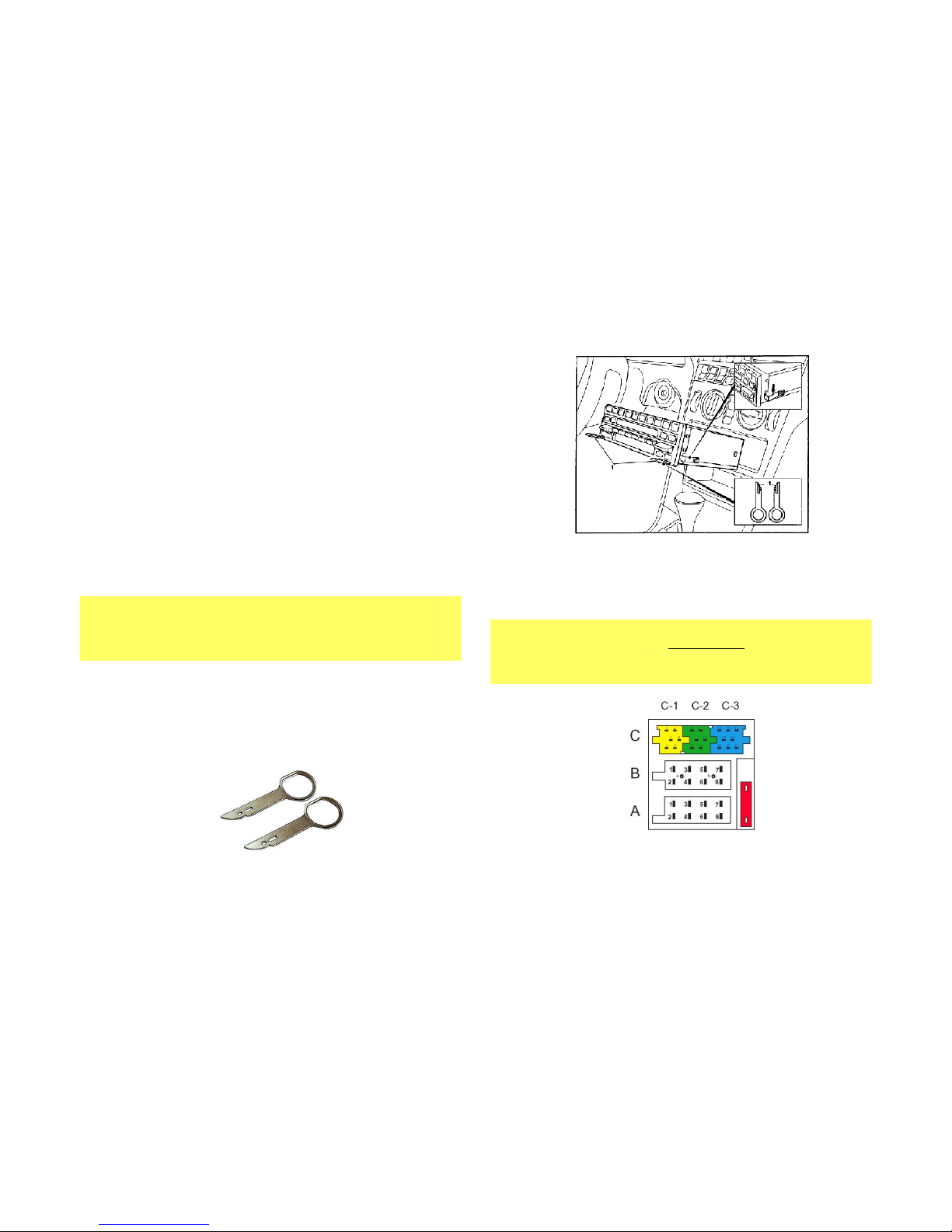
Remove radio from the dashboard to gain access to the
connectors. Special removal tools (See Fig. 1
Fig. 1Fig. 1
Fig. 1) are required to
remove the Becker radio.
Fig. 1
Fig. 1Fig. 1
Fig. 1
Radio removal Tools
1. To remove radio, slide tools into slots to detent position.
Withdraw the radio by pulling outwards. See Fig. 2
Fig. 2Fig. 2
Fig. 2
Fig. 2
Fig. 2Fig. 2
Fig. 2
2. Disconnect the blue, green and yellow plugs (C
CCC----111
1, CCCC----2 and
2 and 2 and
2 and
CCCC----3333) from radio as seen in Fig.
Fig. Fig.
Fig. 3333
Note
NoteNote
Note!!!!
These slots are empty if there is no Changer/amplifier installed. If
vehicle has CD Changer, both the
CD Changer, both the CD Changer, both the
CD Changer, both the bbbblue and green
lue and greenlue and green
lue and green plugs must be
plugs must be plugs must be
plugs must be
disconnected.
disconnected. disconnected.
disconnected. If vehicle has amplifier, the yellow plug must remain
If vehicle has amplifier, the yellow plug must remain If vehicle has amplifier, the yellow plug must remain
If vehicle has amplifier, the yellow plug must remain
connected to C1
connected to C1connected to C1
connected to C1.
Fig.
Fig. Fig.
Fig. 3333
Radio Connectors
Page 3
3. Connect blue plug from the Adapter harness (See Fig.
Fig. Fig.
Fig. 4444) to
slot C----3333 on Radio.
If vehicle has amplifier reconnect the yellow
plug to C-1.
Fig.
Fig. Fig.
Fig. 4444
Audio harness
4. Disconnect 8-way “A”
“A”“A”
“A” plug from Radio (See Fig.
Fig. Fig.
Fig. 3333)
5. Connect the 8-way “A
AAA”””
” plug (from step 4) to matting 8-way
connector on harness (See Fig.
Fig. Fig.
Fig. 5555)
Fig. 5
Fig. 5Fig. 5
Fig. 5
Power harness
6. Connect the 8-way plug from harness to 8-way “A
AAA””””
connector on Radio (vacated in step 4)
7.
Connect the 3.5mm plug from harness (See Fig. 6
Fig. 6Fig. 6
Fig. 6) to
“AUX1”.
Note: If you experienced engine noise connect 3.5mm plug to
“AUX2” on Module. (See Fig. 7
Fig. 7Fig. 7
Fig. 7)
Fig. 6
Fig. 6Fig. 6
Fig. 6
Fig.
Fig. Fig.
Fig. 7777
Module
8. Install the microphone (See Fig. 8
Fig. 8Fig. 8
Fig. 8) to visor and route the
microphone plug end down the side pillar, under the dash
and toward the center and under the dash and connect to the
“MIC” input on the Module (See Fig .
Fig . Fig .
Fig . 7777)
Page 4
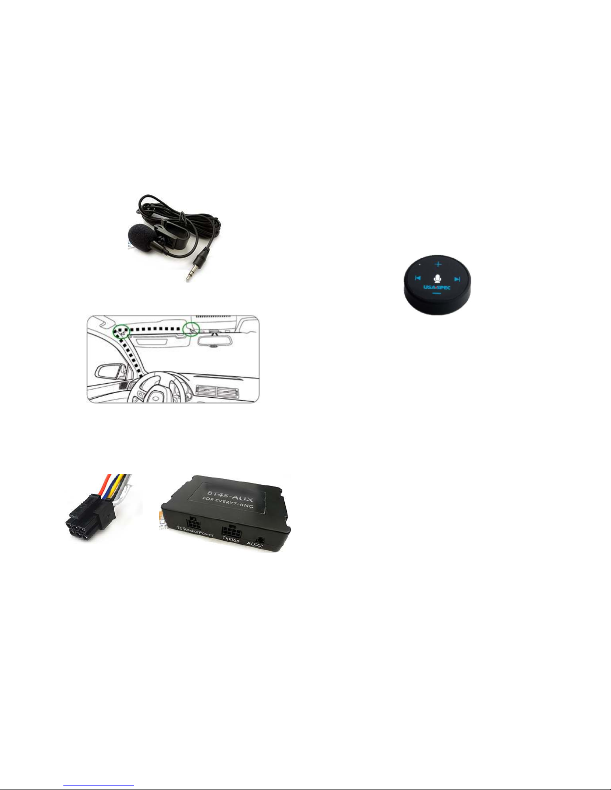
Fig. 8
Fig. 8Fig. 8
Fig. 8
microphone
Fig.
Fig. Fig.
Fig. 9999
9. Connect Bluetooth installation harness 6-pin plug to
“Radio/Power” on Module (See Fig. 1
Fig. 1Fig. 1
Fig. 10000 and 1
and 1and 1
and 11111)
Fig. 1
Fig. 1Fig. 1
Fig. 10000
Fig. 1
Fig. 1Fig. 1
Fig. 11111
10. Twist open control button top and remove battery clear
clear clear
clear
protective
protectiveprotective
protective film. Close cap. Use included double sided tape to
secure remote control button in a convenient location. Avoid
placing over or above airbags or in direct sunlight.
Fig. 9
Fig. 9Fig. 9
Fig. 9
Control button
9. Secure module and proceed to section “Initial Radio Setup
Initial Radio SetupInitial Radio Setup
Initial Radio Setup”.
Sound 5 Installations only
Sound 5 Installations only Sound 5 Installations only
Sound 5 Installations only
((((Mercedes Sprinter)
Mercedes Sprinter)Mercedes Sprinter)
Mercedes Sprinter)
Sound 5 radios do not have 12V
do not have 12V do not have 12V
do not have 12V ACC
ACCACC
ACC wire
wire wire
wire on harness and
because of that the power harness (See Fig. 5
Fig. 5Fig. 5
Fig. 5) is not included in
is not included in is not included in
is not included in
your Kit
your Kityour Kit
your Kit. The 5ft. red wire in your kit must be connected to a
12V ACC supply source i
12V ACC supply source i12V ACC supply source i
12V ACC supply source in vehicle.
n vehicle.n vehicle.
n vehicle. Accessory supply is
available from fuse box or other wiring looms in vehicle when
ignition is turned “ON”. Connect the black wire to radio chassis
as illustrated in Fig. 21
Fig. 21Fig. 21
Fig. 21
Page 5

Fig. 21
Fig. 21Fig. 21
Fig. 21
Ground wire to radio chassis
Initial Radio Setup
Initial Radio SetupInitial Radio Setup
Initial Radio Setup::::
One important step is enabling the AUX and Phone functions within
the Becker radio menu. Most Becker radios are pre-programmed to
recognize a CD Changer connection and because of that you must
perform the following steps and change that setting from CD
Changer to “AUX” otherwise the adapter will not perform as
intended.
Note:
Note:Note:
Note: Becker CDR210, CR210, PCM1 and others without “AUX” function
are not compatible.
Enabling the AUX
Enabling the AUXEnabling the AUX
Enabling the AUX and Phone
and Phoneand Phone
and Phone function
functionfunction
function
Radios with TP button: (e
Radios with TP button: (eRadios with TP button: (e
Radios with TP button: (e....gggg. CDR
. CDR. CDR
. CDR----220)
220)220)
220)
1. Turn radio "ON"
2. Press and hold the "TP" button for about 8 seconds until
Becker 1 is displayed.
3. Turn the Tuning Knob until AUX OFF is displayed.
4. Press either button located directly under the Arrows on the
display to change the present setting from OFF to ON.
Turn radio OFF.
5. Go to Tel
TelTel
Tel and select Ph On
Ph OnPh On
Ph On option
6. Turn Radio back “ON” Press “S
SS
S” button to enter AUX Mode.
This is the mode to use whenever you want to listen to the
device connected to the adapter.
Radios with
Radios with Radios with
Radios with ☼ button: (
button: (button: (
button: (eeee....gggg. BE6104)
. BE6104). BE6104)
. BE6104)
1. Turn Radio “ON”
2. Press and hold the ☼ button for about 8 seconds.
3. Select AUX “ON/OFF” option.
4. Press either button located directly under the Arrows on the
display to change the setting to ON.
5. Go to Tel and select Ph On
Ph OnPh On
Ph On option
6. Turn radio OFF.
7. Turn Radio back ON press the “☼” button until “AUX” is
displayed.
Page 6

Other Radio
Other RadioOther Radio
Other Radios with
s with s with
s with ☼button (e
button (ebutton (e
button (e....gggg. BE4602)
. BE4602). BE4602)
. BE4602)
1. Turn radio ON.
2. Press and hold the ☼ button for 8 seconds, until Becker 1 is
displayed.
3. Turn the Tuning Knob until AUX OFF is displayed.
4. Press either button located directly under the Arrows on the
display to change the present setting from OFF to ON
5. Go to Tel and select Ph On
Ph OnPh On
Ph On option. Turn Radio “OFF”
6. Turn Radio back “ON” Press “CD” button to enter AUX
Mode
Radios with 3 Function buttons (
Radios with 3 Function buttons (Radios with 3 Function buttons (
Radios with 3 Function buttons (eeee....gggg. BE4527)
. BE4527). BE4527)
. BE4527)
1. Turn radio ON.
2. Press and hold Function button #2 (center) for more than 4
seconds.
3. The accompanying menu appears on the display.
4. Press the multifunction button located directly under “AUX”
on the display to change the present setting from OFF to ON.
5. Go to Tel and select Ph On
Ph OnPh On
Ph On option
6. The Setting is stored automatically.
Nav Traffic Radios
Nav Traffic RadiosNav Traffic Radios
Nav Traffic Radios
1. Press the "Radio" button to enter Radio mode.
2. Press the "Navi" and "F10" simultaneously
3. Press "Next" until the AUX input, Changer Res screen
4. Press AUX to enable/disable.
5. Go to Tel and select Ph On
Ph OnPh On
Ph On option
Alternate method:
1. Press the “Sound” button for more than 2 seconds
2. To access user menu second level, press multifunction
button →
3. With multifunction button “AUX” select either “AUX mode
ON” or “AUX mode off”
4. The setting is stored automatically
5. In CD mode, multifunction button “AUX” must be pressed
to select “AUX” mode.
Becker 4775 (Land
Becker 4775 (LandBecker 4775 (Land
Becker 4775 (Land Rover) & Other Traffic Pro
Rover) & Other Traffic ProRover) & Other Traffic Pro
Rover) & Other Traffic Pro
1. With the Radio "ON" press and hold the Tone button until
the sub-menu comes up.
2. Press the soft-key labeled “Aux” until the screen displays
“AUX Mode on”.
3. Go to Tel and select Ph On
Ph OnPh On
Ph On option
4. Press the Tone button to exit the menu.
5. To enter "AUX" mode, press the "CD" button and select the
"AUX" soft-key.
Page 7

Sound 5 (BE7077 Sprinter Van)
Sound 5 (BE7077 Sprinter Van)Sound 5 (BE7077 Sprinter Van)
Sound 5 (BE7077 Sprinter Van)
1. Turn radio ON.
2. Press the
dp
dpdp
dp
repeatedly until EXT menu appear.
3. Turn Rotary control knob clockwise and select EXT AUX.
4. Go to Tel and select Ph On
Ph OnPh On
Ph On option
5. Press the CD button repeatedly until “AUX” is displayed
Cascade Pro (i.e. BE7941)
Cascade Pro (i.e. BE7941)Cascade Pro (i.e. BE7941)
Cascade Pro (i.e. BE7941)
To activate the External Device mode
To activate the External Device mode To activate the External Device mode
To activate the External Device mode
1. Turn radio ON.
2. Press the information button
3. Turn the rotary control/push (OK) button counterclockwise
until System Settings appears at the top right of the display
4. Press the rotary control/push (OK) button
5. Turn the rotary control /push (OK) button to select External
Device
6. Confirm selection by pressing the rotary control/push (OK)
button
7. Select “AUX” from list and turn it “ON”.
8. Go to Tel and select Ph On
Ph OnPh On
Ph On option
8. Exit menu
9. To listen to the “AUX” device, press the MEDIA button
10. Turn the rotary control /push (OK) button to “AUX” and
press the rotary control/push (OK) button
Becker BE7801 Infotainment (Ferrari, Maserati)
Becker BE7801 Infotainment (Ferrari, Maserati)Becker BE7801 Infotainment (Ferrari, Maserati)
Becker BE7801 Infotainment (Ferrari, Maserati)
1. Press the TP button for more than 2 seconds
2. Press multifunction button “AUX”
3. Select Ext audio source
4. press the right control knob to select “ON”
5. Go to Tel and select Ph On
Ph OnPh On
Ph On option
6. The setting is store automatically
Becker DTM /High speed (
Becker DTM /High speed (Becker DTM /High speed (
Becker DTM /High speed (eeee....gggg. BE
. BE. BE
. BE ----7892, BE7910)
7892, BE7910)7892, BE7910)
7892, BE7910)
1. Press the Sound
SoundSound
Sound button for more than 2 seconds
2. Press multifunction button “AUX”
3. Select Aux Mode on
Aux Mode onAux Mode on
Aux Mode on
4. Go to Tel and select Ph On
Ph OnPh On
Ph On option
5. The setting is stored automatically
In CD Operation, the multifunction button AUX must be
pressed to select AUX operation
Page 8

Enabling the
Enabling the Enabling the
Enabling the Phone
Phone Phone
Phone function
functionfunction
function
Pairing
PairingPairing
Pairing
Pairing varies from Phone to Phone but the basic steps are the same.
This process is done upon initial install and will not have to be
repeated
1. Turn Ignition and Radio “ON”
Blue LED in adapter peephole will flash (pairing mode)
2. On A2DP device: go to
Settings, Wireless & Networks,
Settings, Wireless & Networks, Settings, Wireless & Networks,
Settings, Wireless & Networks,
Bluetooth Settings
Bluetooth SettingsBluetooth Settings
Bluetooth Settings
3. Select
Bluetooth
BluetoothBluetooth
Bluetooth
and turn on, select Bluetooth settings
4. Tap
Scan for devices
Scan for devicesScan for devices
Scan for devices
.
5.
Wait for the Bluetooth device name to appear and select it.
Once paired the Blue LED inside peephole will blink once every 3
seconds and confirmation tone is heard on car speakers
Pairing
Pairing Pairing
Pairing second device
second devicesecond device
second device
To pair a second device you must un-pair the first by pressing/holding the
control button for 2 seconds or more, (listen for confirmation tone). Follow
pairing instructions to pair second device
Warning!
Warning!Warning!
Warning!
Voice Recognition applications (e.g. Siri, Google Play etc.) must
be enabled on device as you would in portable mode.
Test Operation
Test OperationTest Operation
Test Operation
BBBBluetoo th Pairing and Con nection
luetooth Pairing and Connectionluetooth Pairing and Connection
luetooth Pairing and Connection
This process is required the first time you use the BT45-BKR. After
initial pairing, the BT45-BKR will automatically reconnect with the
paired phone upon entering the vehicle.
1. Turn vehicle ignition “ON”.
2. Turn Radio “ON” and to “AUX” Mode
3. Access your Smartphone Bluetooth menu settings, and
search (scan) for available devices.
4. Select the BT45 and click “Connect”
5. Upon pairing you will hear “Connected” on car speakers
Page 9

Pairing a
Pairing a Pairing a
Pairing a second device (Multi
second device (Multisecond device (Multi
second device (Multi----point)
point) point)
point)
1. Turn vehicle ignition “OFF”.
2. Disable Bluetooth on fist phone (already paired)
3. Turn vehicle ignition “ON”
4. Turn Radio “ON” and to “AUX” Mode
5. Enable Bluetooth on second phone and search (scan) for
available devices
6. Select the BT45 and click “Connect”
7. Upon paired you will hear “Connected” on car speakers
8. Turn ignition “OFF”
9. Enable Bluetooth on First phone
10. Turn ignition back “ON”
11. Turn radio “ON” and to “AUX” mode
12. Both phones will automatically connect. You should hear
“Connected, Connected” confirming both devices have been
successfully connected
Wireless
Wireless Wireless
Wireless Remote Control
Remote ControlRemote Control
Remote Control
1. Twist open the remote control bottom cap (turn
counterclockwise)
2. Remove battery’s protective clear film so battery negative
terminal comes in direct contact with circuit board.
3. Blue LED will now flash when tapping remote buttons
4. Close cap
5. Use included double-side tape to place remote control at a
location that is most convenient. Avoid placing the remote
control over or around airbags or under direct sunlight.
Wireless Remote Control Battery
Wireless Remote Control BatteryWireless Remote Control Battery
Wireless Remote Control Battery
The LED on remote control will blink 10 times to indicate the battery
is low. Replace battery with a 3V CR2032 by following these steps:
1. Turn vehicles ignition to “OFF”
2. Twist open the remote control bottom cap and remove
battery (observe polarity)
3. Turn vehicles ignition to “ON” and radio to “AUX” mode
and within 60 seconds install new battery
4. You will hear a long beep through the radio at the same time
the remote control’s LED will turn solid blue followed by 10
flashes
5. If remote LED does not flash 10 time, repeat steps 2 -5
Wireless Remote Control Functions
Wireless Remote Control FunctionsWireless Remote Control Functions
Wireless Remote Control Functions
Page 10

To Enable/Disable Voice Prompt
To Enable/Disable Voice Prompt To Enable/Disable Voice Prompt
To Enable/Disable Voice Prompt
+Caller Announcement
+Caller Announcement+Caller Announcement
+Caller Announcement
1. Stop all active calls and or media streaming
2. Press button on remote control to enable feature: you will
hear “Voice Enabled”
3. Press button on remote control to disable feature: You will
hear “Voice Disabled”
Media
Media Media
Media Streaming Operation
Streaming OperationStreaming Operation
Streaming Operation
If you have 2 phones paired you can stream music from either one.
1. Set the radio to AUX mode
2. Launch your preferred music app
3. Use wireless remote control to adjust volume, change tracks etc.
4. To switch between phones, simply pause first phone and press
play on second device and vice versa
Hands
HandsHands
Hands----Free
FreeFree
Free Phone Call
Phone CallPhone Call
Phone Call
Operation
OperationOperation
Operation
Answer and end calls.
1. Set the radio to AUX mode (if not already set)
2. To answer call, press the button on remote control or
answer directly on phone*
3. To reject call or end press the button on remote control
4. Phone call audio can be adjusted by remote control, phone
control, radio volume or steering wheel control buttons
*
if you answered call directly from your phone, phone audio will go
through the phone. You must select BT45 from your phone screen to
redirect call
Placing Calls
Placing CallsPlacing Calls
Placing Calls
1. Tap the button on remote control to initiate voice
command or make call directly from phone
2. Press button on remote control to end call
Keep in mind that the environment inside a moving vehicle tends to be
noisier. This will directly affect how accurately the phone’s voice
recognition picks up your voice commands
Notes:
Notes:Notes:
Notes:
1.
If playback is distorted, adjust volume on Bluetooth device.
2.
Voice command compatible with Apple (Siri), Android (Google
Now), Blackberry (Assistant)
If successful go ahead and Reinstall the Radio
Congratulations, you’ve just updated your vehicle to support new
technology while preserving the original radio and dash components.
Enjoy!
Page 11

Bluetooth Adapter Comparison
Bluetooth Adapter Comparison Bluetooth Adapter Comparison
Bluetooth Adapter Comparison
Chart:
Chart:Chart:
Chart:
Feature
FeatureFeature
Feature
BLU-BKR A2D-BKR BT45-BKR A2DIY-BKR BKR-HF
CD Changer Retention × x x x x
3.5mm AUX input x x x ✓ ✓
USB Charging Port x x x ✓** ✓
Mute Audio System ✓* ✓* ✓ ✓* ✓*
Hands-Free Profile × × ✓ ✓ ✓
Streaming Audio ✓ ✓ ✓ ✓ ✓
Control button × × ✓ ✓ ✓
Plug-n-play ✓ ✓ ✓ ✓ ✓
* Radio must be in “AUX” Mode
** Optional
Frequent
FrequentFrequent
Frequent asked questions
asked questionsasked questions
asked questions
1. My
My My
My vehicle has a CD Changer. Do I have to disconnect it for this
vehicle has a CD Changer. Do I have to disconnect it for this vehicle has a CD Changer. Do I have to disconnect it for this
vehicle has a CD Changer. Do I have to disconnect it for this
adapter to work?
adapter to work?adapter to work?
adapter to work?
YES
YESYES
YES; CD Changer must be disconnected
must be disconnectedmust be disconnected
must be disconnected (both blue and green plugs)
(both blue and green plugs)(both blue and green plugs)
(both blue and green plugs)
2. Does the
Does the Does the
Does the BT45
BT45BT45
BT45----BKR work on all Becker Radios?
BKR work on all Becker Radios?BKR work on all Becker Radios?
BKR work on all Becker Radios?
NO
NONO
NO; works on Becker radios with “AUX” input
with “AUX” inputwith “AUX” input
with “AUX” input and “PHONE”
and “PHONE”and “PHONE”
and “PHONE”
capabilities
capabilitiescapabilities
capabilities.
. .
. Porsche
Porsche Porsche
Porsche CR
CRCR
CR----210, CDR
210, CDR210, CDR
210, CDR----210,
210, 210,
210, CR
CRCR
CR----1 etc.
1 etc. 1 etc.
1 etc. do not have aux
do not have aux do not have aux
do not have aux
inputs and
inputs and inputs and
inputs and requires the BKRCD
requires the BKRCDrequires the BKRCD
requires the BKRCD----HF
HF HF
HF + CD Changer
+ CD Changer+ CD Changer
+ CD Changer....
3. Can I control my Smartphone music from the radio buttons?
Can I control my Smartphone music from the radio buttons?Can I control my Smartphone music from the radio buttons?
Can I control my Smartphone music from the radio buttons?
NO;
NO;NO;
NO; you must
must must
must continue to use Phone
continue to use Phonecontinue to use Phone
continue to use Phone built
builtbuilt
built----in controls
in controlsin controls
in controls or the
or the or the
or the
wireless
wireless wireless
wireless remote
remote remote
remote control
controlcontrol
control and
andand
and////or voice commands
or voice commandsor voice commands
or voice commands.... Volume button on
the Becker radio can used to set playback level.
4. Can I play
Can I play Can I play
Can I play a non
a nona non
a non----Bluetooth device (e.g. MP3 Player, Satellite Radio
Bluetooth device (e.g. MP3 Player, Satellite Radio Bluetooth device (e.g. MP3 Player, Satellite Radio
Bluetooth device (e.g. MP3 Player, Satellite Radio
etc.
etc.etc.
etc. )?
)?)?
)?
NO;
NO;NO;
NO; unlike our BKRCD-HF, the BT45-BKR does not have a hard wired
input for non-Bluetooth devices.
5.
Will the stereo mute when I receive or make a phone call?
Will the stereo mute when I receive or make a phone call?Will the stereo mute when I receive or make a phone call?
Will the stereo mute when I receive or make a phone call?
YES
YESYES
YES;;;; the radio will mute when a call is initiated or received.
6. My second phone can’t pair or locate the Bluetooth device
My second phone can’t pair or locate the Bluetooth deviceMy second phone can’t pair or locate the Bluetooth device
My second phone can’t pair or locate the Bluetooth device????
In order to pair with another phone you must turn OFF Bluetooth on
first phone. Second phone will not pair.
DDDDisclaim er
isclaimerisclaimer
isclaimer
• This product has no affiliation with Porsche or Becker
• There are no warranties expressed or implied by purchase of this product
• We’re not liable for misuse of this product.
© 1995-Jul-17 Discount Car Stereo, Inc. All rights reserved. Information in this
document is subject to change without notice. Other products and companies referred
to herein are trademarks or registered trademarks of their respective companies or
mark holders.
 Loading...