

Page 1

BECK-O-TRONIC 6
Version: Centronic
en
Assembly and Operating Instructions
Door control unit
Important information for:
• Fitters / • Electricians / • Users
Please forward accordingly!
These instructions must be kept safe for future reference.
4005 630 202 0b09/08/2018
Becker-Antriebe GmbH
Friedrich-Ebert-Straße 2-4
35764 Sinn/Germany
www.becker-antriebe.com
Page 2

Table of contents
General ................................................................................................................ 3
Warranty .............................................................................................................. 3
Safety instructions ................................................................................................ 4
Intended use ........................................................................................................ 6
Product overview .................................................................................................. 7
Assembly ............................................................................................................. 8
Wiring .................................................................................................................. 9
Operator controls & functions/displays ..................................................................10
Parametrisation ...................................................................................................15
Menu table ..........................................................................................................16
Connections & functions.......................................................................................22
Reset / factory setting ..........................................................................................29
Functional description ..........................................................................................30
Remote control....................................................................................................34
Disposal ..............................................................................................................36
Maintenance .......................................................................................................36
Cleaning..............................................................................................................37
Error messages ...................................................................................................37
Complete connecting diagram ..............................................................................40
Electric safety edge and light barrier connecting diagram........................................41
Safety edge OSE connecting diagram ...................................................................42
Technical data .....................................................................................................42
Declaration of conformity .....................................................................................43
2
Page 3
General
This control unit is a high-quality product with many features and advantages:
• Simple, convenient connection
• Easy to handle and highly flexible
• Automatic limit position detection
• Defined buttons for OPEN, STOP and CLOSE, also on the hand-held transmitter
• Design with clear display of operating status and error messages
• Optical safety edge or electric safety edge and additional light barrier can be con-
nected
Please observe these Assembly and Operating Instructions when installing and setting
up the equipment.
Explanation of pictograms
CAUTION
ATTENTION
CAUTION indicates a hazardous situation
which, if not avoided, could result in injury.
ATTENTION indicates measures that must be
taken to avoid damage to property.
Denotes user tips and other useful information.
Warranty
Structural modifications and incorrect installation which are not in accordance with
these and our other instructions can result in serious injuries, e.g., crushing of limbs.
Therefore, structural modifications may only be carried out with our prior approval and
strictly in accordance with our instructions, particularly the information contained in
these Assembly and Operating Instructions.
Any further processing of the products which does not comply with their intended use is
not permitted.
The end product manufacturer and fitter have to ensure that all the relevant current
statutory, official and, in particular, EMC regulations are adhered to during utilisation of
our products, especially with regard to end product manufacture, installation and customer advice.
3
Page 4

Safety instructions
The following safety instructions and warnings are intended to avert hazards and to
prevent property damage and personal injury.
Please keep the instruction manual safe!
Caution
• Work on the electrical equipment may only be carried
out by a qualified electrician.
• The relevant safety and accident prevention regulations
for the specific application must be observed when carrying out assembly, installation, commissioning, testing
and maintenance of the control unit. The following regulations in particular must be observed (not an exhaustive
list):
- Machinery Directive 2006/42/EC
- EN 12453 (safety in use of power-operated doors, requirements)
- EN 12445 (safety in use of power-operated doors,
testing methods)
- EN 12978 (safety devices for power-operated doors,
requirements and testing methods)
- EN 60335 (safety of electrical devices for household or
similar purposes)
- Fire prevention regulations
- Accident prevention regulations ASR A1.7 (power-operated windows, doors and gates)
• The engineer responsible for fitting the system must en-
sure proper installation, instruction of the operator in its
use and issue of the CE mark.
• The operator must ensure that the system is only oper-
ated in perfect condition and that the safety devices are
checked regularly by an expert to ensure they are in full
working order.
• A damaged mains connecting cable must be replaced
immediately by a qualified electrician.
4
Page 5

• If there is no fixed stop, e.g., when using roller doors,
the customer must ensure that the roller shutter curtain
is protected and cannot cause any dangerous situations, e.g., by overrunning a limit position.
• The control unit is designed to have a service life of
100,000 operating cycles.
• Drives with a H05VV-F connecting cable may only be
used indoors. If the cable is installed outdoors, it must
be placed in a protective conduit.
• The person who installs, connects, commissions and
maintains this control unit must have read, understood
and observed these Assembly and Operating Instructions. The manufacturer will not accept liability for damage, consequential damage or malfunctions resulting
from non-compliance with these Assembly and Operating Instructions.
• Before working on the control unit, it must be discon-
nected from the power supply and measures must be
taken to ensure it cannot be inadvertently switched back
on.
• Following installation and commissioning, all users must
receive instruction in the functions and operation of the
system. All users must be briefed on the dangers posed
by the system, as well as the risks and their testing obligations as users. Documentation of these points is recommended.
• Operating personnel who have not received instruction
or children must not operate the door control unit.
• Persons, animals or objects must not be within the
movement range of the door when opening or closing it.
• As the setting options are many and varied, it is also
possible to make settings for the specific system being
operated that are obviously illogical, impermissible or
even dangerous. This is not due to a fault or defect at
5
Page 6

the control unit. In light of this, the installer / person responsible for the system must carefully check the settings made and modify them as necessary.
Intended use
The type of control unit described in these instructions may only be used for the operation of tubular drives in roller doors which have fixed stops at the limit positions or a
cover on the barrel (EN 12453). The radio receiver can be operated using any transmitter of the Centronic range of control units (with the exception of transmitters with a time
switching function and / or sun protection function). For travel in the DOWN direction in
maintained operation, a closing edge safety device is necessary.
This type of control unit must not be used in potentially explosive areas.
Other applications, uses and modifications are not permitted in order to protect the
safety of the users and others, since these actions can impair the system’s safety and
carry the risk of personal injury and property damage. The manufacturer does not accept liability for damage or injury arising from such actions.
Always observe the information in these instructions when operating or repairing the
system. The manufacturer does not accept liability for damage or injury resulting from
improper use.
6
Page 7
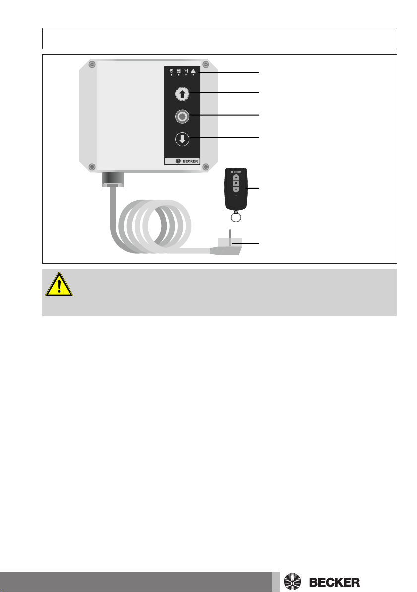
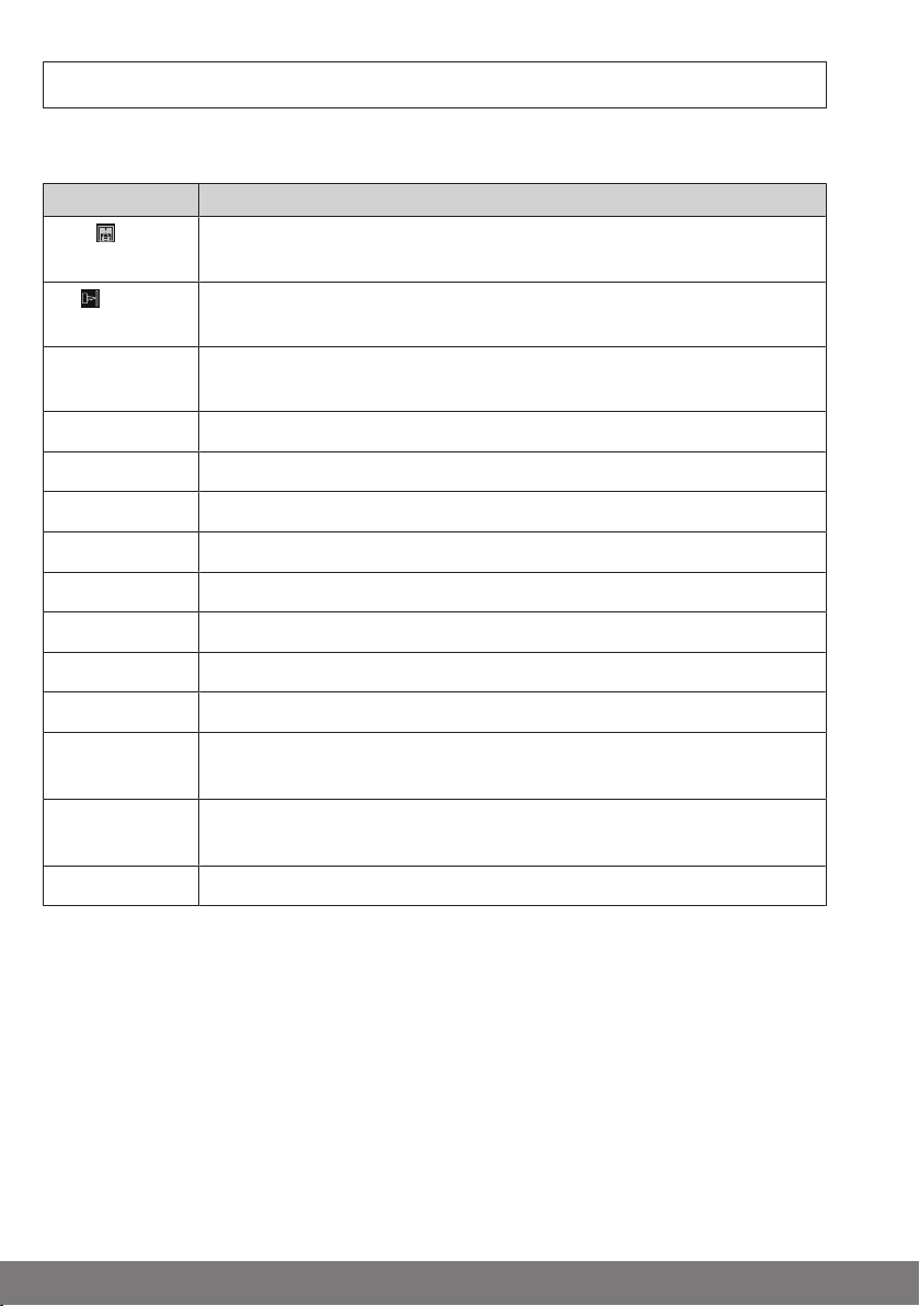
Product overview
Status display
OPEN button
STOP button
CLOSE button
Hand-held transmitter
Mains plug
Caution
Work on the electrical equipment may only be carried out
by a qualified electrician.
7
Page 8
Assembly
Check that the transmitter and receiver are functioning perfectly prior to installation in
the desired location. Do not choose an installation location that is exposed to electromagnetic fields, e.g., in the immediate vicinity of contactors (power relays), mains
transformers, ignition transformers, fluorescent tubes, etc., or their connecting cables.
Protect the control unit against direct solar radiation and driving rain.
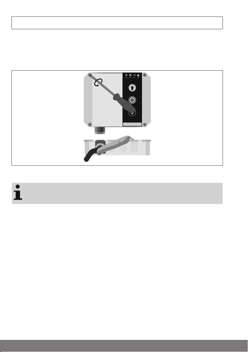
Open the cover of the control unit. Pull the cable from the cover off and carefully place
the cover to one side. Remove the required cut-outs in the bottom part of the housing.
Cut in at the edges to make the cut-outs easier to remove.
Install the control unit at a suitable operating height (at least 1500 mm from the
ground). Mount the housing with 4 screws (max. diameter of screw head 7.5 mm) inserted through the holes provided in the corners.
Plug the cable from the cover back on and adjust the parameters. You can now close
the control unit.
8
Page 9
Wiring
Connect the individual pieces of equipment as shown in the connecting diagram.
Caution
Electrical work may only be carried out by qualified electricians or trained personnel. Always disconnect the
safety mains plug before connecting the equipment. The
connection to the building wiring system must be established in accordance with the Machinery Directive using an
adequately sized mains disconnection device. This can be
done by using a plug connection or lockable main switch.
The control unit is protected by a 5 AT, 5 x 20 mm fuse located below the shock-hazard protection cover. Switch the
operating voltage off before replacement!
First, pull the insert sleeves over the connecting cable and
then push the insert sleeves into the bottom part of the
housing once all of the wires have been connected. The
control and drive lines (e.g., pulse, open, stop, close...)
must not exceed a max. length of 30m! This does not apply to the power line. Always route the power line, drive
and control lines in separate cables at a distance from one
another. Non-compliance with the above can lead to malfunctions!
9
Page 10
Operator controls & functions/displays
Explanation of abbreviations
Abbreviation Description
USA
Bottom rail sensor; sensor of main closing edge safety device. Detects obstructions when the door is lowering
LS
AWZ
M
[Ta.+]
[Ta.-]
[Ta.F]
[Ta.M]
SE1
SE2
[Kl.1]..[Kl.25]
[M.A0]..
[M.C9]
[Er.01]..
[Er.25]
[F1]..[F2]
Light barrier; for use in buildings as monitoring device for door system and to control the automatic reclosing operation.
Automatic reclosing; the door lowers automatically after the set reclosing time.
Drive
"+" on the PCB
"-" on the PCB
"Radio" button on the PCB
"Menu" button on the PCB
Safety input 1
Safety input 2
Reference to connecting terminals
Menu table "Setting a function", menu items "A0" to "C9"
Error message, shown in the display
Radio module function, shown in the display
10
Page 11
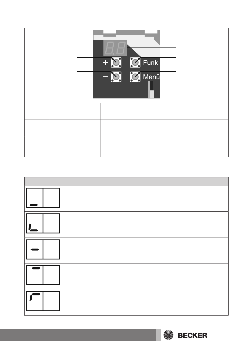
Function of buttons
Display
[Ta.F]
[Ta.M]
[Ta.+]
[Ta.-]
[Ta.+] + value Change menu item and OPEN / STOP in OPEN direc-
tion
[Ta.-] - value Change menu item and CLOSE / STOP in CLOSE dir-
ection
[Ta.F] Radio button For programming / deleting radio settings
[Ta.M] Menu button Menu selection / display of input status
Display on left "Door status"
Display on left Segment status Door status
Lit In the CLOSE limit position
Lit
Lit Between limit positions
Lit In the OPEN limit position
Permanently in the CLOSE limit position
Holiday function: Inputs / radio disabled
Flashes
Permanently in the OPEN limit position
Automatic reclosing off, external inputs
and radio deactivated
11
Page 12
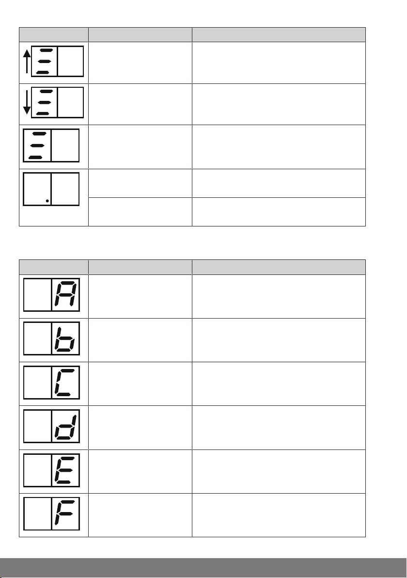
Display on left Segment status Door status
Bars running up Running up
Bars running down Running down
A bar is at a standstill +
flashes with 50% on and
50% off
Lit Automatic reclosing Stay-open time run-
Flashes Stay-open time after exiting light barrier
Advance warning time running
ning
running
Display on right "Status of inputs"
Display on right Segment status Input
Flashes EMERGENCY STOP actuated
Flashes SE1 (LS / SE /OSE) actuated
Flashes SE2 (LS / SE /OSE) actuated
Flashes OPEN actuated
12
Flashes CLOSE actuated
Flashes Pulse actuated
Page 13
Display on right Segment status Input
Flashes Pre-limit switch actuated
Item on right lights up Control unit sends status via transmit
module
Membrane keypad
Labelling Function Function:
short press
OPEN OPEN command Permanently open:
STOP Drive operation in pro-
gress: STOP
If the drive is at a standstill:
Light on/off, if light function
is set with overrun time
CLOSE CLOSE command Permanently closed: Holi-
While the "STOP" button is pressed or a safety device in
the emergency stop circuit has triggered, door travel is
not possible.
Function:
press > 5 s
Automatic reclosing, external inputs and radio disabled.
Steady light:
Light permanently on
day function, external inputs and radio disabled.
13
Page 14

Status indications
The status indicator shows the current status of the control unit. You can find this above
the OPEN button.
Program radio
1-channel operation
Fault in USA circuit On Flashes - Flashes
Internal fault
(no redundancy)
Control unit defective
(replacement necessary)
Error, negative testing
(pre-limit switch possibly too high)
Error
Running time exceeded
AWZ cancelled,
LS actuated and USA
actuated
AWZ cancelled,
USA actuated
Flashes - - -
On Flashes Flashes Flashes
- On On On
On Flashes - -
On - - Flashes
On On On On
On On - On
AWZ cancelled,
LS actuated
AWZ cancelled On - - On
No error,
USA actuated
No error,
LS actuated
No error,
ready
14
On - On On
On On - -
On - On -
On - - -
Page 15

Caution
If an internal error occurs (no redundancy), the system
changes over to dead-man mode for safety reasons.
The door can only be lowered via the CLOSE button at the
control unit.
Testing
Pneumatic safety edges are tested for safety-related reasons during every downward
movement. This process is called testing.
Self-test
The control unit performs a self-test cyclically. CH = Check appears once in the display
and the relays are audibly actuated.
Parametrisation
The operator control is structured in two levels
Level 1 (highest level) = selection of menu item or function
Level 2 (lowest level) = selection of menu values / setting values
Parameter editing Display
1. Control unit in door status
display
Display of current door position and statuses
2. [Ta.M] Press menu button > 3 s Displays the last menu item
called up
3. [Ta.+]
or
[Ta.-]
4. [Ta.M] Briefly press menu button Current menu value 00..99
5. [Ta.+]
or
[Ta.-]
6. [Ta.M] Briefly press menu button Save the menu value and
7. [Ta.M] Press menu button > 3 s Exit the menu
Briefly press + or - value Selection of required menu
item according to select
menu table
Briefly press + or - value Selection of required menu
value
display menu item
no operation for > 15 s Control unit in door status
display
A0
A1
or
A0
A0
15
Page 16

If no changes in the menu values are possible, the entire
control panel is protected against readjustment. Enable
via item "Disable/enable parametrisation".
The drive cannot operate during the adjustment.
Basic values = factory setting
Menu table
Menu
item
A0
A1
A2
Menu
value
RUNNING TIME LIMITATION
00..90 Maximum drive running time 1...90 s, in 1 s increments
91..99 Maximum drive running time 1...9 min, in 1 min increments
LIMIT POSITION DETECTION
00
Running time without drive current monitoring
(observe "Type of limit position detection via running time or limit switch" without fail!)
01 Running time and drive current monitoring 01
SAFETY INPUT SE1: Type
00 No SE safety edge connected
01 LS (without external testing)
02 LS (with external testing)
03 1K2
04 8K2 04
Function / value Basic
Setting
values
60
16
05 OSE
06 OSE (special: 400 Hz / 12 V)
Page 17

Menu
item
A3
Menu
value
Function / value Basic
SAFETY INPUT SE1: FUNCTION
Setting
values
Travel in CLOSE direction:
00 No effect No effect
01 Stop No effect
02 Reverse travel No effect
03 Reopening No effect
04 No effect Stop
05 Stop Stop
06 Reverse travel Stop 06
07 Reopening Stop
08 No effect Reverse travel
09 Stop Reverse travel
10 Reverse travel Reverse travel
11 Reopening Reverse travel
12 No effect Reclosing
13 Stop Reclosing
14 Reverse travel Reclosing
Travel in OPEN direction:
15 Reopening Reclosing
A4
SAFETY INPUT SE2: Type
00 No SE safety edge connected
01 LS (without external testing) 01
02 LS (with external testing)
03 1K2
04 8K2
05 OSE
06 OSE (special: 400 Hz / 12 V)
17
Page 18

Menu
item
A5
Menu
value
Function / value Basic
SAFETY INPUT SE2: FUNCTION
Setting
values
Travel in CLOSE direction:
00 No effect No effect
01 Stop No effect
02 Reverse travel No effect
03 Reopening No effect 03
04 No effect Stop
05 Stop Stop
06 Reverse travel Stop
07 Reopening Stop
08 No effect Reverse travel
09 Stop Reverse travel
10 Reverse travel Reverse travel
11 Reopening Reverse travel
12 No effect Reclosing
13 Stop Reclosing
14 Reverse travel Reclosing
Travel in OPEN direction:
18
15 Reopening Reclosing
A6
01..10 Stay-open time 5...50 s, in 5 s increments, excl.
11..40 Stay-open time 11=1 min, 12=2 min, … 40=30 min
A7
01..20 Stay-open time 1...20 s, in 1 s increments
AUTOMATIC RECLOSING
00 Off 00
advance warning time
excl. advance warning time
STAY-OPEN TIME AFTER EXITING THE LIGHT
BARRIER (SE2)
00 Function switched off 00
Page 19

Menu
item
A8
Menu
value
LIGHT / WARNING LIGHT
00 Only during advance warning time and drive oper-
ation
01..60 Light time 10...600 s, in 10 s increments 12
61
Display: On, if the door is in the OPEN limit position
62
Display: On, if the door is in the CLOSE limit position
63
Display: On, if the door is not in the OPEN limit position (e.g., red traffic light)
64
Display: On, if the door is not in the CLOSE limit
position (e.g., red traffic light)
Off, 5 s after CLOSE limit position
65 Only during advance warning time and motor oper-
ation, 1 Hz flashing
Function / value Basic
values
Setting
A9
01..15 Advance warning time 1...15 s, in 1 s increments
b0
01..15 Advance warning time 1...15 s, in 1 s increments
b1
00..19 Reverse travel time 0.25...5.00 s, in 0.25 s incre-
b2
ADVANCE WARNING TIME PRIOR TO TRAVEL
IN THE OPEN DIRECTION
00 Off 00
ADVANCE WARNING TIME PRIOR TO TRAVEL
IN THE CLOSE DIRECTION
00 Off 00
REVERSE TRAVEL TIME
ments
AUTOMATIC RECLOSING following EMERGENCY STOP
00 Automatic reclosing following EMERGENCY STOP
disabled
01 Rerun of automatic reclosing following EMER-
GENCY STOP release
11
00
19
Page 20

Menu
item
b3
Menu
value
OPEN INPUT & MEMBRANE-TYPE KEY
00 Travel in the OPEN direction with panic function
01 Travel in the OPEN direction without panic function 01
02 Dead-man function
Function / value Basic
Setting
values
b4
b5
b6
CLOSE INPUT & MEMBRANE-TYPE KEY
00 Travel in CLOSE direction with panic function
01 Travel in CLOSE direction without panic function 01
02 Dead-man function
PRE-LIMIT SWITCH
00 Operation without pre-limit switch 00
01 Operation with pre-limit switch
SLAT ADJUSTMENT
00 Operation without slat adjustment 00
01 Operation with slat adjustment
• A short command (< 1 s) via pulse, OPEN,
CLOSE or radio effects a slat adjustment
• A long command (> 1 s) via pulse, OPEN,
CLOSE or radio leads to travel to the relevant
limit position
The slat adjustment is only effective if the OPEN
and CLOSE inputs are also operated in combination with the "with panic function" setting. To do
this, [M.b3] = 00 or [M.b4] = 00 must be set.
b7 00
b8
b9
20
DEAD TIME when reversing/switching the running direction
00..39 0.025...1.000 s, in 0.025 s increments 09
STANDBY for 12 V output (terminal 12)
00 12 V permanently on 00
01 12 V off in standby mode
Page 21

Menu
item
C0 00
C1 00
C2 00
C3 00
C4 00
Menu
value
Function / value Basic
values
Setting
C5
01..99 Maintenance interval 100…9,900 door move-
C6 No function 00
C7
C8
C9
MAINTENANCE INTERVAL
00 No maintenance interval 00
ments, in increments of 100
Disable/enable parametrisation
00 Menu items adjustable 00
01 Menu items not adjustable
Changeover:
Press EMERGENCY STOP, [Ta.+ ] and [Ta.-] simultaneously,
Toggle between 00 and 01 with [Ta.M]
Version number (only readable)
Display of 8-digit version number by running a sequence of digits.
Example: Rest - 00 - 01 - 05 - 12 - Rest, etc. corresponds to version number 00.010512
Clock counter (only readable)
6-digit display of movements in the OPEN direction
by running a sequence of digits.
Example: Rest - 00 - 35 - 17 - Rest, etc. corresponds to 3,517 movements in the OPEN direction
21
Page 22

Connections & functions
Mains connection
[Kl.1]..[Kl.2] Protective conductor / PE
[Kl.3] L-conduction
[Kl.4] N-conductor
Light / warning light
[Kl.1]..[Kl.2] Protective conductor / PE
[Kl.5] L-conductor (enabled)
[Kl.6] N-conductor (enabled)
• 230 V / AC output, max. 250 VA, all-pole disconnection
• The light function is set via [M.A8]
• With [M.A8] = 00, the light is actuated for the set advance warning time [M.A9] or
[M.b0] and the drive operation time.
• With [M.A8] = 01 to 60, the light is actuated throughout the entire drive operation
and following a drive operation for the selected time. With the setting 04 to 60, the
light goes out briefly once 10 s before the time expires and signals the pending
time rundown.
• With [M.A8] = 61 to 64, a red/green traffic light or door status indicator can be im-
plemented; in this case the light output is actuated according to the door position
(OPEN or CLOSE limit position).
• With [M.A8] = 65 the output flashes with 1 Hz during the advance warning time
and drive operation.
Drive / tubular drive
[Kl.1]..[Kl.2] Protective conductor / PE
[Kl.7] CLOSE direction, 230 V / AC output
[Kl.8] OPEN direction, 230 V / AC output
[Kl.9] N-conductor (enabled)
• 230 V / AC output, max. 500 VA, all-pole disconnection
22
Page 23

Drive / tubular drive
• The drive must travel in the OPEN direction following "Operating voltage / mains
voltage on" and the first pulse command. If the drive travels in the CLOSE direction even though the bars in the display are moving up, the connecting wires
[Kl.7]+[Kl.8] must be swapped round.
EMERGENCY STOP (safety input)
[Kl.10] EMERGENCY STOP input
[Kl.11] EMERGENCY STOP (12 V permanent)
• Safety input category 1 to EN ISO 13849-1/2008 (directly switches the relay for
direction of travel off)
• Input for EMERGENCY STOP control sensor
• NC contact, floating
• Several control sensors can be connected in series.
• If an EMERGENCY STOP input is not used it must be jumpered! The jumper must
be removed when it is in use.
• The automatic reclosing function after an EMERGENCY STOP is adjusted in
[M.b2]
• The EMERGENCY STOP input switches the drive and light relay off directly and is
therefore still effective when the electronics fail!
• After an EMERGENCY STOP command when the drive is in operation, the door
travels in the opposite direction (away from the source of danger) the next time a
pulse command is given.
• After an EMERGENCY STOP command when the door is at a standstill, travel in
the OPEN direction generally occurs the next time a pulse command is given.
12 V DC output (stabilised)
[Kl.11] +12 V DC (stabilised), I
[Kl.12]
• +12 V DC testing of light barriers and/or switching off of LS
< 300 mA (total [Kl.11] + [Kl.12])
max
and OSE at standstill
• [M.b9] = 00, +12 V permanently on, although briefly off dur-
ing self-test
• [M.b9] = 01, +12 V off in standby mode and briefly off dur-
ing self-test
23
Page 24

12 V DC output (stabilised)
[Kl.18] 0V / Earth
[Kl.20] 0V / Earth
Connection for external consumer, e.g., OSE, light barrier, etc.
Attention!The maximum current specified in the "Technical data" must not be
exceeded! Non-compliance can lead to malfunctions, failure, destruction and
property damage.
Safety input
[Kl.11] +12 V (continuous)
[Kl.12] +12 V (with testing)
[Kl.13] SE1 signal input
[Kl.14] Common
[Kl.15] SE2 signal input
[Kl.18] or [Kl.20] 0V / Earth
• Safety input category 2 / Performance Level C to EN ISO 13849-1/2008
• The type of the input is set in [M.A2] for SE1 and [M.A4] for SE2.
∙ Input for safety contact strips (1k2 or 8k2 or OSE) for closing edge safety device
∙ Input for light barriers (LS)
• The function of the input is set in [M.A3] for SE1 and [M.A5] for SE2.
∙ Setting the function of the safety input for travel in the OPEN direction and travel
in the CLOSE direction
∙ Stop: Drive remains at standstill
∙ Reverse travel: When approaching an obstruction, the door is actuated in the
opposite direction for the set reverse travel time [M.b1].
∙ Reopening/reclosing: If a safety device is actuated when the drive is in operation
(e. g., detects obstruction in the active direction of travel) the door then travels
in the opposite direction up to the limit position.
• When the SE input is actuated the drive can only be started if the SE setting is
not effective in the corresponding direction of travel. If effective, travel will not be
possible in the direction of travel.
• When the drive is in operation a command at the SE input effects the following:
stop, reverse travel, reopening, reclosing or no effect, depending on the direction
of travel and setting.
24
Page 25

Safety input
• When the automatic reclosing is active and the SE input is actuated, the stay-
open time is reset until the input is once again enabled.
• The input has a safety function and is monitored by self-testing of the electronics.
If an error is detected in the SE input, door travel is not possible. SE1: Display
{Er.08} / {Er.10} SE2: Display {Er.09} / {Er.11}
• If control sensors (1k2 / 8k2 / OSE / LS) at safety inputs SE1 / SE2 are defective,
the control unit can be manually operated in dead-man mode in the OPEN or
CLOSE direction.
• Actuate the control sensor briefly twice in the required travel direction then
hold actuated. The door now travels in dead-man mode.
• If a pneumatic pressure-wave safety edge (DW edge) is used, its function must
be tested. An external pre-limit switch is needed for this. The pre-limit switch is
only effective in combination with the safety input SE1 and is activated with
([M.b5] = 1). Depending on the type of edge, the safety input SE1 must either be
set as 1k2 ([M.A2] = 3) or as 8k2 ([M.A2] = 4).
Attention
[Kl.14] = Common. Must not be connected to 0 V = [Kl.18]
or [Kl.20] as otherwise the SE input is defective or is not
functioning!
External safety devices must be approved for protection
against personal injury.
The pre-limit switch is only effective in combination with
the safety input SE1!
Light barriers with an OC (open collector output, PNP /
NPN semi-conductor output) cannot be used (malfunction!)
Safety input SE1 (LS / 1k2 / 8K2 / OSE)
1k2 / 8k2 connection
[M.A2] 03: 1k2
[M.A2] 04: 8k2
[Kl.13] Electric safety edge
[Kl.14] Electric safety edge
OSE connection
25
Page 26

Safety input SE1 (LS / 1k2 / 8K2 / OSE)
[M.A2] 05: Standard OSE
[M.A2] 06: 400 Hz
[Kl.11] +12 V (brown)
[Kl.18] or [Kl.20] Earth (white)
[Kl.13] Signal (green)
LS connection without external testing
[M.A2] 01
[Kl.11] LS: +12V
[Kl.18] or [Kl.20] Earth
[Kl.13] and [Kl.14] Relay output LS
LS connection with external testing
[M.A2] 02
[Kl.12] LS transmitter: +12V
[Kl.18] or [Kl.20] Earth
[Kl.11] LS receiver: +12V
[Kl.13] and [Kl.14] Relay output LS
During the self-test of the control unit, the +12 V = [Kl.12] to the LS transmitter is
briefly interrupted. The LS receiver must detect this and switch the relay output
[Kl.13] and [Kl.14].
Safety input SE2 (LS / 1k2 / 8K2 / OSE)
1k2 / 8k2 connection
[M.A4] 03: 1k2
[M.A4] 04: 8k2
[Kl.15] Electric safety edge
[Kl.14] Electric safety edge
OSE connection
[M.A4] 05: Standard OSE
[M.A4] 06: 400 Hz
[Kl.11] +12 V (brown)
26
Page 27

Safety input SE2 (LS / 1k2 / 8K2 / OSE)
[Kl.18] or [Kl.20] Earth (white)
[Kl.15] Signal (green)
LS connection without external testing
[M.A4] 01
[Kl.11] LS: +12V
[Kl.18] or [Kl.20] Earth
[Kl.14] and [Kl.15] Relay output LS
LS connection with external testing
[M.A4] 02
[Kl.12] LS transmitter: +12V
[Kl.18] or [Kl.20] Earth
[Kl.11] LS receiver: +12V
[Kl.14] and [Kl.15] Relay output LS
During the self-test of the control unit, the +12 V = [Kl.12] to the LS transmitter is
briefly interrupted. The LS receiver must detect this and switch the relay output
[Kl.14] and [Kl.15].
Light barrier (LS)
• Light barriers can be connected to the safety inputs SE1 and SE2.
• Light barriers with a semiconductor / open collector output cannot be used.
• The connection is established according to item Safety input SE1 (LS /
1k2 / 8K2 / OSE) or Safety input SE2 (LS / 1k2 / 8K2 / OSE).
• When the automatic reclosing is active and the LS input is actuated, the stay-open
time is reset until the input is once again enabled.
• The function " Stay-open time after exiting the light barrier" is set in [M.A7]
and only applies for the light barrier at SE2! If the light barrier is exited when the
door is open, the door closes after the set stay-open time [M.A7]. During this time
the item in the left-hand display flashes. An LS command (e.g., a car driving
through) while the door is still travelling in the OPEN direction is saved (only with
setting [M.A3] = 00 to 03). As soon as the door is in the OPEN limit position, the
set stay-open time [M.A7] runs down and automatic travel in the CLOSE direction
starts.
27
Page 28

OPEN input
[Kl.16] OPEN input
[Kl.18] 0V / Earth
• Input for push-button, key-operated push-button, external radio, etc.
• NO contact, floating
• Several control sensors can be connected in parallel.
• With [M.b3] = "dead-man function", radio operation for the corresponding direc-
tion of travel is disabled.
• The door stops when the OPEN and CLOSE inputs are simultaneously actuated.
Further running direction commands (radio, pulse, membrane keypad) are not
executed.
• When the advance warning time is set [M.A9], the door start is delayed.
CLOSE input
[Kl.17] CLOSE input
[Kl.18] 0V / Earth
• Input for push-button, key-operated push-button, external radio, etc.
• NO contact, floating
• Several control sensors can be connected in parallel.
• The function of the input is set in [M.b4]
• With [M.b4] = "dead-man function", radio operation for the corresponding direc-
tion of travel is disabled.
• The door stops when the OPEN and CLOSE inputs are simultaneously actuated.
Further running direction commands (radio, pulse, membrane keypad) are not
executed.
• When the advance warning time is set [M.b0], the door start is delayed.
28
Page 29

Pulse input
[Kl.19] Pulse input
[Kl.20] 0V / Earth
• Input for push-button, key-operated push-button, external radio, etc.
• NO contact, floating
• Several control sensors can be connected in parallel.
• If the door is in the OPEN limit position, only the stay-open time is reset via a pulse
or OPEN command. The stay-open time remains reset for as long as a pulse or
OPEN command is applied. The stay-open time only starts to run down when an
OPEN/pulse command is no longer applied.
• When the automatic reclosing is active ([M.A6] > 0 or [M.A7] > 0), a pulse com-
mand always effects travel in the OPEN direction. The same applies if the door is
already travelling in the CLOSE direction. The stay-open time restarts.
• Commands for specific OPEN / CLOSE are also effective when the automatic re-
closing is active.
Pre-limit switch
[Kl.21] Pre-limit switch signal input
[Kl.20] 0V / Earth
When the safety input (SE1) is actuated < 2 s after actuation of the pre-limit switch,
travel in the CLOSE direction continues up to the limit position. Deactivation is effected via the internal limit switch in the tubular drive [M.A1] = 01 or via running time
[M.A1] = 00. If the safety input (SE1) is not actuated (active testing e.g., for pneumatic safety edge) < 2 s after actuation of the pre-limit switch, reverse travel or reopening occurs depending on the setting in the menu [M.A3].
The pre-limit switch is only effective in combination with safety input SE1!
No effect in combination with SE2.
Reset / factory setting
The factory setting of the control unit can be restored if required (basic values in accordance with menu table). Press and hold the buttons [Ta.+] and [Ta.-] for approx. 5 s
until the display changes from "r E" to "CH". The entire control unit must be subsequently readjusted!
Programmed hand-held transmitters are not deleted during this process.
29
Page 30

Functional description
Type of limit switch detection via running time or limit switch
During commissioning, the type of limit position detection must be set in [M.A1].
• Running time switch off [M.A1] = 00
∙ This operating mode may only be used with systems where there is no risk in-
volved in doing so, or where this risk is safeguarded by another means. The drive
cut-off is not monitored during the self-test!
∙ The maximum running time can be set in [M.A0] to increments of 1 - 90 s and 91 -
99 min.
∙ With limit position detection based on running time [M.A0] = 00, an error message
is not displayed if the set running time is exceeded; instead, the drive is stopped
and this is interpreted as the limit position.
∙ The door position is not determined, i.e.: every run continues until the total run-
ning time has elapsed. This is also the case if the door was at an "intermediate position" and therefore reaches the limit position before the running time has
elapsed. This operating mode can be used for hydraulic drives with mechanical
limit stop, for example.
• Internal limit switch [M.A1] = 01
∙ If the door travels to the internal limit switch (tubular drive), this is detected as the
limit position and the drive is switched off. To do this, the running time limit [M.A0]
set must be longer (normally +5 s) than the actual running time.
Dead time during reversal
• The minimum dead time for which every drive must be at a standstill before the op-
posite direction can be actuated is set in [M.b8].
• This function is particularly important when changing the running direction in com-
bination with reverse travel/reopening via SE1 / SE2.
Attention
Drives exist that do not run in the opposite direction and
continue running in the original direction instead if the
dead time is too short (especially drives with low selfblocking capability). With these drives, the time must be
increased until start-up in the opposite direction can be
ensured during reversal.
If necessary, check that the force values have been observed once the dead time has been increased!
30
Page 31

Drive / tubular drive operation
• The control unit is ideally designed for tubular drives with internal limit switches that
switch off the corresponding direction of travel directly. The control unit evaluates
the drive current and can thus identify the limit positions.
• Operation with external limit switches is possible. External limit switches must be
approved for 230 V and be able to switch the drive current. The connection is established in the corresponding drive cable. The installation must be 230 V capable.
When operated with tubular drives, the internal limit switches must be set so that
they do not trigger a deactivation at any point on the required travel distance! To do
this, the switch-off point can be set approx. 3 revolutions before the starting point
and after the end of the travel distance.
Attention
When operating with external limit switches, special attention must be paid to the safety regulations!
Panic function
• When the "panic function" is active and the door is in motion, the door travel stops
the first time the input is actuated. The second time the input is actuated, the door
starts moving in the actuated direction.
• If actuation occurs when the door is running in the opposite direction and a "panic
function" is not set, the door stops and immediately starts moving in the opposite
direction. If actuation occurs in the same direction (current travel direction), this
has no effect.
Automatic reclosing
• If the door is not in the CLOSE limit position, the automatic reclosing operation
takes effect after the stay-open time expires [M.A6]. The warning light output is
active for the set advance warning time [M.b0] before the door travels to the
CLOSE limit position.
• If the door is in the OPEN limit position, only the stay-open time is reset via a pulse
or OPEN command. The stay-open time remains reset for as long as a pulse or
OPEN command is applied. The stay-open time only starts to run down when an
OPEN/pulse command is no longer applied.
• When the automatic reclosing is active, a pulse command always effects travel in
the OPEN direction. The same applies if the door is already travelling in the CLOSE
direction. The stay-open time restarts.
• Commands for specific OPEN / CLOSE are also effective when the automatic re-
closing is active.
31
Page 32

• If switch-off via SE1 / SE2 occurs three times in succession during travel in the
CLOSE direction, the automatic reclosing is blocked after the third unsuccessful attempt to travel in the CLOSE direction until the next pulse, OPEN, CLOSE or radio
command. However, this only applies for setting type = 1k2 / 8k2 or OSE.
• If [M.b2] = 00, following actuation of the EMERGENCY STOP the automatic reclos-
ing is blocked until the next pulse, OPEN, CLOSE or radio command. If the drive is
at a standstill, only the stay-open time is reset when SE1 or SE2 is actuated (no
switch-off). The stay-open time only starts running down once the inputs have no
longer been actuated. When the automatic reclosing is active, it is always effective
if the door is not in the CLOSE limit position. While SE1 or SE2 is actuated, travel in
the CLOSE direction does not occur.
• A continuous signal at the OPEN input blocks/interrupts the automatic reclosing.
Once the OPEN signal is removed, the stay-open time runs down, then the door
closes. The potential-free contact of a timer allows the automatic reclosing operation to be controlled.
Standby power / standby operation
• In order to save the standby power, the control unit enters standby mode 15 s after
the last function (door travel or light off). All internal consumers (display, etc.),
apart from the radio module, are switched off or their power reduced.
• External control sensors (LS, OSE, etc.) can also optionally be switched off [M.b9]
via the 12 V output [Kl.12]. However, following standby mode it takes around another +0.5 s to restart the drive.
Holiday function / door permanently open / door permanently
closed / steady light
• Functions only possible in combination with membrane keypad
∙ Door permanently open (all control inputs and the automatic reclosing are dis-
abled). Press OPEN at membrane keypad for longer than 5 s.
∙ Door permanently closed (holiday function, all control inputs are disabled). Press
CLOSE at membrane keypad for longer than 5 s.
∙ Light permanently on. Press Stop at membrane keypad for longer than 5 s.
• Switching off: Press OPEN, STOP or CLOSE at the membrane keypad
• The permanently OPEN and permanently CLOSE functions are also retained when
the operating voltage fails.
32
Page 33

Emergency operation - dead-man
• If control sensors (1k2 / 8k2 / OSE / LS) at safety inputs SE1 / SE2 are defective,
the control unit can be manually operated in dead-man mode in the OPEN or
CLOSE direction.
• Emergency operation can be controlled via the OPEN and CLOSE inputs, [Ta.+] /
[Ta.-], and also the membrane keypad.
• Actuate the control sensor briefly twice in the required travel direction then hold ac-
tuated. The door now travels in dead-man mode.
Disable/enable parametrisation
• All menu items can be disabled in [M.C7] to prevent readjustment. (recommended)
• [M.C7] = 00 menu items can be modified (as-delivered condition)
• [M.C7] = 01 no changes possible
• Disable/enable parametrisation
∙ Continuously actuate EMERGENCY STOP
∙ Select menu [M.C7] and access menu item with [Ta.M]
∙ Press and hold buttons [Ta.+] and [Ta.-]
∙ You can now toggle between the values 00 and 01 with [Ta.M]
Clock counter
• The number of previous door movements can be read out as 6 digits in [M.C9].
• Every start in the OPEN direction is counted.
• After [M.C9] is selected, a sequence of digits runs down 6 times in the display. This
sequence of digits shows the number of OPEN movements, starting after the rest.
Example: Rest - 00 - 35 - 17 - Rest, etc. corresponds to 3,517 movements in the
OPEN direction.
• The travel counter cannot be reset or modified (read-only memory).
33
Page 34

Maintenance interval
• The number of door movements (movements in OPEN direction) that elapse before
the next maintenance message is displayed; set in [M.C5].
• The light output flashes when the drive is in operation to indicate that maintenance
is due.
• To switch off the maintenance message, [M.C5] must be changed. (i.e. if the main-
tenance interval is to remain the same, the menu item must be changed once and
reset to the old value). When [M.C5] is changed, the maintenance counter is set to
the value that is currently set.
• [M.C5] only shows the set maintenance interval. The counter itself cannot be read
out.
• A maintenance message is also retained when the operating voltage fails.
• The maintenance interval is independent of the clock counter [M.C9] and cannot
be reset.
Remote control
Caution
If a radio control system is used, the person operating the
door must have full view of the door and its surroundings
while the door is moving and ensure that he/she is clear of
all hazardous areas.
It is only possible to operate the control unit with one
transmitter when a safety device is connected. A programmed transmitter is indicated by the value F1 or F2.
Operate the programming button on the transmitter using
a suitable cylindrical tool (e.g. a ballpoint pen).
Transmitters with a timer cannot be programmed. It is not
possible to program intermediate positions. Automatic
timer control functions are not executed via the transmitter. A central command must be programmed into the control unit separately.
The function of the radio remote control is determined when programming the transmitter. Up to 27 codings (27 transmitters) with different functions can be programmed.
Operation via a transmitter is not possible with dead-man.
34
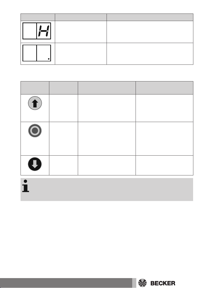
Page 35

Value Function
Open button
Stop/Light button
Close button
Button with
pulse sequence
{F1} Triple push-button, Open-Stop/Light-Close
{F2} Pulse (Open-Stop-Close-..)
Transmitter:
{F1} Open-Stop/Light-Close {F2} Pulse
Programming a transmitter:
1. Press [Ta.F] < 1 s until {F1} flashes in the display
2. Select the required function with [Ta.+] or [Ta.-]
3. Now press and hold the operating or programming button on the transmitter until
the selected function {F1}, {F2} is permanently displayed (no longer flashes). The
transmitter has now been programmed.
4. If a transmitter is not programmed, learning mode is automatically exited after 3
minutes.
Deleting a transmitter
1. Press [Ta.F] < 1 s until {F1} flashes in the display.
2. Now press and hold the programming button of the transmitter until {FL} appears
permanently in the display.
35
Page 36

Deleting all transmitters
1. Press and hold the button [Ta.F] until {FL} flashes in the display after which the {FL}
display goes off.
2. All codings have now been deleted.
Antenna connection
1. An antenna wire must be connected to [Kl.23].
2. When using a stick antenna, the shielding of the coaxial cable and inner conductor
must be connected to [Kl.22] and [Kl.23] respectively. The cable can be fed into
the housing via a free cable bushing.
You can maximise the range by routing the antenna wire or
coaxial cable as far as possible from mains, control and
drive cables. Routing in cable ducts alongside other
cables will reduce the range and possibly lead to malfunctions!
If the dead-man function has been set via [M.b3] / [M.b4],
the corresponding direction of travel cannot be radio controlled!
If a programmed radio signal is received, the programmed
function {F1}, {F2} appears in the display.
Radio communication is blocked while a button on the
control unit or membrane keypad is actuated.
Disposal
This product is made of various materials which must be disposed of properly. Find out
about the applicable regulations on recycling or disposal for this product in your country.
The packaging material must be disposed of properly.
Maintenance
This control unit is maintenance-free.
36
Page 37

Cleaning
Only clean the outside of the housing with a suitable cloth. Do not use cleaning agents,
as these may damage the plastic.
Error messages
"Er" (Error) and the relevant error number flash alternately in the display to signal an error.
Error no. Description of error Comment / measure
01 EEprom data Switch off operating voltage, wait 10 s,
switch operating voltage back on. If the
error message persists, the saved menu
parameters are no longer correct. The
control unit must be reset (item Reset /
factory setting) and readjusted.
02 Motor current detection Switch off operating voltage, wait 10 s,
switch operating voltage back on. If the
error message persists, the motor current
detection is faulty. The control unit must
be replaced.
03 N-relay cutoff Switch off operating voltage, wait 10 s,
switch operating voltage back on. If the
error message persists, a short-circuit
has occurred in the N-relay. The control
unit must be replaced.
04 OPEN/CLOSE relay Switch off operating voltage, wait 10 s,
switch operating voltage back on. If the
error message persists, a short-circuit
has occurred in the OPEN or CLOSE relay.
The control unit must be replaced.
05 Watchdog test Switch off operating voltage, wait 10 s,
switch operating voltage back on. If the
error message persists, there is an error
in the control unit hardware. The control
unit must be replaced.
37
Page 38

Error no. Description of error Comment / measure
06 ROM test Switch off operating voltage, wait 10 s,
switch operating voltage back on. If the
error message persists, there is an error
in the controller hardware. The control
unit must be replaced.
07 RAM test Switch off operating voltage, wait 10 s,
switch operating voltage back on. If the
error message persists, there is an error
in the controller hardware. The control
unit must be replaced.
08 LS / SE1 (internal test-
ing)
09 LS / SE2 (internal test-
ing)
Switch off operating voltage, wait 10 s,
switch operating voltage back on. If the
error message persists:
a) Check setting [M.A2] when the closing
edge safety device is connected.
b) Check connection of the closing edge
safety device, especially earth connection
at terminal [Kl.14].
c) If a) and b) are correct, an error possibly exists in the control unit hardware.
The control unit must be replaced.
The door can be operated in emer-
gency mode.
Switch off operating voltage, wait 10 s,
switch operating voltage back on. If the
error message persists:
a) Check setting [M.A4] with regard to
connected closing edge safety device.
b) Check connection of the closing edge
safety device, especially earth connection
at terminal [Kl.14].
c) If a) and b) are correct, an error possibly exists in the control unit hardware.
The control unit must be replaced.
The door can be operated in emer-
gency mode.
38
Page 39

Error no. Description of error Comment / measure
10 LS / SE1 (external test-
ing)
Switch off operating voltage, wait 10 s,
switch operating voltage back on. If the
error message persists:
a) Check setting [M.A2] (external LS test)
with regard to connected light barrier.
b) Check connection of LS transmitter in
accordance with item Safety input SE1
(LS / 1k2 / 8K2 / OSE).
c) If a) and b) are correct, an error possibly exists in the control unit hardware.
The control unit must be replaced.
The door can be operated in emer-
gency mode.
11 LS / SE2 (external test-
ing)
20 SE1 The last door operation was stopped via
21 SE2 The last door operation was stopped via
22 EMERGENCY STOP The last door operation was stopped via
23 Pre-limit switch The pre-limit switch was actuated without
Switch off operating voltage, wait 10 s,
switch operating voltage back on. If the
error message persists:
a) Check setting [M.A4] (external LS test)
with regard to connected light barrier.
b) Check connection of LS transmitter in
accordance with item Safety input SE2
(LS / 1k2 / 8K2 / OSE).
c) If a) and b) are correct, an error possibly exists in the control unit hardware.
The control unit must be replaced.
The door can be operated in emer-
gency mode.
an SE1 command.
an SE2 command.
an EMERGENCY STOP command.
SE1 being actuated within 2 s.
39
Page 40

Complete connecting diagram
PE
L
N
Outdoor light
Drive
Emergency Stop
Electric safety edge
Travel command OPEN
Pre-limit switch
Travel command pulse
Travel command CLOSE
Light barrier
3 4 5 6 7 8N9
230V
AC
Licht
230V
PE
NL
M
NOT-
12V
10 11 12 13 14 15 16 17 18 19 20 21 22
LS/SE/OSE
SE1 SE2C
Test
Auf Zu
Impuls
24
0V Vor-ES
23
0V
25
ANT.
1
2
8K2
40
Page 41

Electric safety edge and light barrier connecting
C
8K2
C
NO
NC
-
+
+
Light barrier transmitter
Light barrier receiver
Electric safety edge
diagram
41
Page 42

Safety edge OSE connecting diagram
brown
green
white
Technical data
Dimensions of the housing (W x H x D) 155 x 130 x 50 mm
Housing material PC
Degree of protection IP54, only for installation indoors
Supply voltage 230 V / 50 Hz (connection type Y)
Input power 6 V A
Fuse 5 A slow-blow Si3, 5 x 20 mm
Drive switching capacity 1 drive 230 V / 50 Hz maximum 500 V A
Light switching capacity 230 V / 50 Hz maximum 250 V
Control voltage 12 V maximum 300 mA
Temperature range -20°C…..+50°C
Radio frequency 868.3 MHz
Weight approx. 0.5 kg (without connecting cable)
42
Page 43

Declaration of conformity
43
Page 44

 Loading...