

Becker AR6201-000, AR6201-002 Installation And Operation Manual

Installation and Operation
Manual DV 14300.03
Issue 2 October 2010
Becker Flugfunkwerk GmbH ● Baden Airpark ● 77836 Rheinmünster ● Germany
Telephone +49 (0) 7229 / 305-0 ● Fax +49 (0) 7229 / 305-217
http://www.becker-avionics.com ● e-mail: info@becker-avionics.de
VHF-Transceiver
AR6201-(XXX)
FIRST ISSUE AND CHANGES
Issue 1 May 2010
Issue 2 October 2010
LIST OF EFFECTIVE PAGES
Page No.: Date: Page No.: Date:
Cover Page
10/2010
1-I … 1-II 10/2010
1-1 … 1-10 10/2010
2-I … 2-II 10/2010
2-1 … 2-26 10/2010
3-I … 3-II 10/2010
3-1 … 3-14 10/2010
DV 14300.03 / Article Number 0617.857-071
© 2010 by Becker Flugfunkwerk GmbH / All rights reserved

AR6201
DV 14300.03/.04 Issue 2 10/2010 Page 1-I
Table of contents
Section 1 GENERAL DESCRIPTION Page
1.1 Introduction 1
1.2 Purposeofequipment 1
1.3 GeneralNotes 1
1.4 ShortDescription 2
1.5 Variantssurvey 4
1.6 Technicaldata 4
1.6.1 Powersupplydata 4
1.6.2 Generaldata 4
1.6.3 Dimensions&Weight 5
1.6.4 Receiverdata 5
1.6.5 Transmitterdata 5
1.6.6 Software 6
1.6.7
Approval 6
1.7 EnvironmentalQualification 7
1.8 Accessories 9

AR6201
Page 1-II DV 14300.03/.04 Issue 2 10/2010
Blank

AR6201
DV 14300.03/.04 Issue 2 10/2010 Page 1-1
Section 1 GENERAL
1.1 Introduction
This manual describes the VHF transceiver AR6201-(XXX). The manuals DV 14300.03
(“Installation and Operation”) and DV 14300.04 (“Maintenance and Repair”) contain the following
sections.
Section DV 14300.03 DV 14300.04
1 General X X
2 Installation X X
3 Operation X X
4 Theory of operation N/A X
5 Maintenance and Repair N/A X
6 Illustrated Parts List N/A X
7 Modification and Changes N/A X
8 Circuit Diagrams N/A X
1.2 Purpose of equipment
The VHF transceiver enables voice communication in the very high frequency band between
118.000 MHz to 136.9916 MHz (radio communication part of air-band) with a selectable channel
spacing of 25 kHz or 8.33 kHz.
1.3 General Notes
The word “frequency” in this document is also used in the sense of “channel name” as defined in
EUROCAE, ED-23B, chapter 1.3.2.
The word “memory channel” or “channel” used in this document means a memory place identified
by a channel number. On that memory place a frequency may be stored for later use.
AR6201
Page 1-2 DV 14300.03/.04 Issue 2 10/2010
1.4 Short Description
The VHF transceiver is designed as a single block unit for usage in cockpit environment of general
aviation aircrafts including helicopters under consideration of performed environmental qualification
(refer chapter 1.7) and SW Level (refer chapter 1.6.6).
The VHF transceiver is a compact and lightweight single block unit. The dimensions correspond to
the standard instrument diameter of 58 mm (2 1/4 inch). Mounting is by means of four screws (rear
panel installation). All controls and indicators are located on the front panel. The equipment
connectors and the antenna socket are located at the rear of the unit.
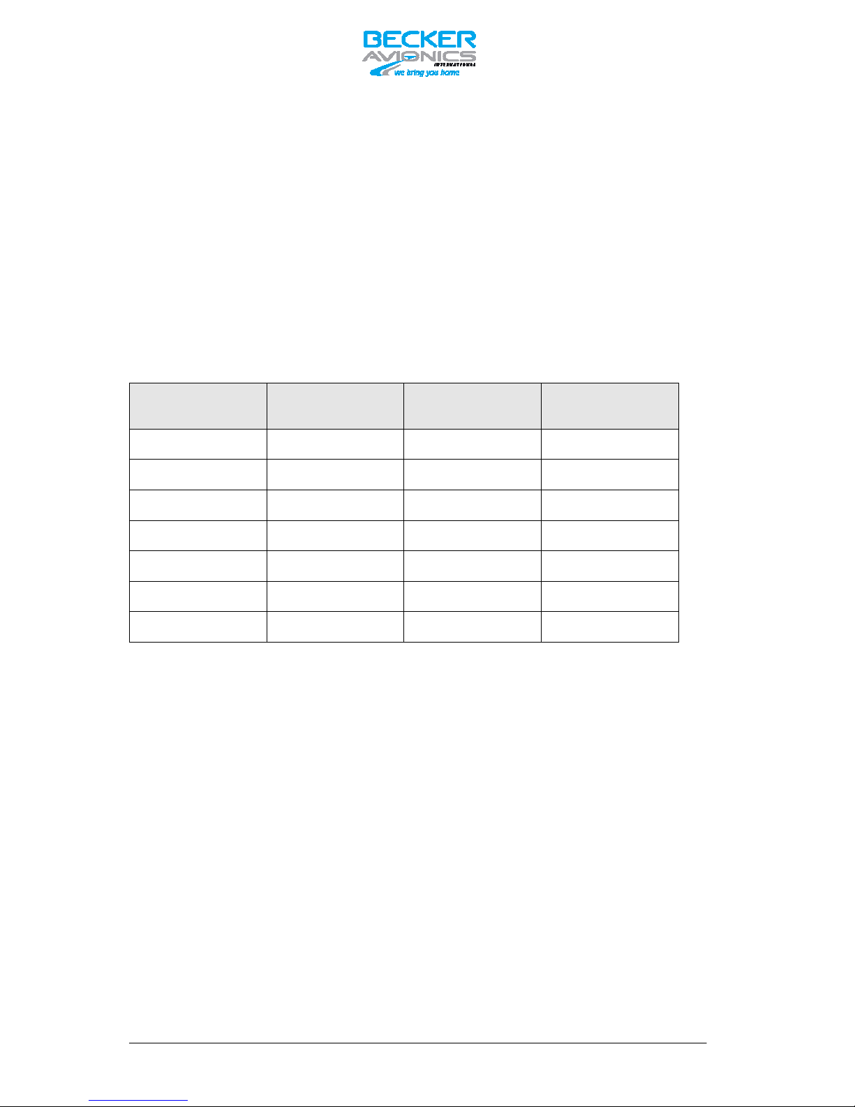
Frequency Indication
The frequency indication is done by means of a liquid crystal display (LCD). The required operating
frequency is set with the rotary knob. The relation between the real operating frequency and the
displayed frequency is according to standards (ED-23B, chapter 1.3.2). For overview refer table
below.
Operating Frequency
(MHz)
Channel Spacing
(kHz)
Displayed Frequency
in 8.33+25 kHz
mixed Mode
Displayed Frequency
in 25 kHz Mode
118.0000 25 118.000 118.00
118.0000 8.33 118.005 N/A
118.0083 8.33 118.010 N/A
118.0166 8.33 118.015 N/A
118.0250 25 118.025 118.02
etc. etc. etc. etc.
136.9916 8.33 136.990 N/A
Audio outputs
The transceiver includes two audio outputs: Headphone and Speaker. The Headphone rated
output power is 300 mW into 150 Ohm. The rated output power from the Speaker Output is 4 W
into 4 Ohm.
Mike inputs
The VHF transceiver has an input for dynamic microphone (DYN_MIKE) and an input for standard
microphone (STD_MIKE). Each input is able to operate with single microphone or with 2
microphones of the same type connected in parallel.
AF auxiliary input
The AF auxiliary input enables to connect an external audio source (NAV, music-player …) to the
transceiver. The external audio will be audible only when transceiver is in receive operation.
Sidetone
The sidetone is available on the headphone output during transmission. The sidetone volume is
coupled with the Intercom Volume.

AR6201
DV 14300.03/.04 Issue 2 10/2010 Page 1-3
Squelch Operation
There are two kinds of squelch methods implemented, carrier squelch and noise squelch. The
carrier squelch is based on received signal strength and adjustable in installation setup; the noise
squelch is based on detected noise level and adjustable in pilot setup.
Memory channels
The VHF transceiver also contains a channel memory device for automatically/manually storage of
99 frequencies. The last 9 used (active) frequencies are always stored automatically. In addition a
manual storage of up to 90 different frequencies is possible.
Intercom operation
Aircraft internal communication via connected headsets is possible due to the internal built in
intercom. Intercom operation may be triggered automatically via VOX (adjustable) or externally via
intercom switch. Setting of VOX-threshold and Intercom Volume is accessible by pilot in the
intercom menu.
Scan Mode
In scan mode (also called dual watch function) the device is capable to monitor two frequencies
(active & preset) at the same time.
Illumination
The illumination of LCD and push buttons can be controlled either internally from the front panel
knob or externally via the dimming inputs. In case of external dimming the illumination curve
(brightness to voltage relation) can be adjusted in the installation setup.
LOW BATT Indication
The VHF transceiver also contains a monitoring stage for the power supply voltage. If the supply
voltage drops below the adjustable threshold, the display indicates the message “LOW BATT”. The
factory setting for that adjustable threshold is 10.5 V.
Emergency operation
In emergency operation (from 9.0 to 10.25 V) the performance of the device is degraded:
For TX Mode: RF Rated power is ≥ 2 W @ 50 Ohm, modulation depth is ≥ 50 %,
For RX Mode: (S+N)/N ≥ 6 dB for RF level -93 dBm, m = 30%, 1 kHz sine
Panel Backlight is switched off
Speaker output is switched off. Only the headphone output is still operating.
CAUTION:
For power supply voltages below 10 V the speaker output of the transceiver is automatically
switched off, without dedicated notification of the user. !
Depending on settings of installation setup “LOW BATT” may be indicated if supply voltage drops
below predefined threshold.
If this threshold is adjusted in range 10.2 … 10.5V this “LOW BATT” warning may also indicate to
the user, that he should connect his headset (because speaker may be switched off soon).
Built In Tests
After switch on, the unit performs a self test (PBIT). During PBIT the transceiver shows “WAIT” and
the corresponding software versions of the control head and chassis module. During normal
operation a continuous built in test (CBIT) verifies the correct operation of the unit in background. In
case of problems a warning or failure message will be displayed.
AR6201
Page 1-4 DV 14300.03/.04 Issue 2 10/2010
Installation Setup
Configuration of the installation parameters like mike sensitivity, mike type selection, speaker
enable/disable and further parameters is possible via Installation Setup.
Service Mode
Special factory configuration of the system is possible in Service Mode via a RS422 interface with a
proprietary serial data communication protocol.
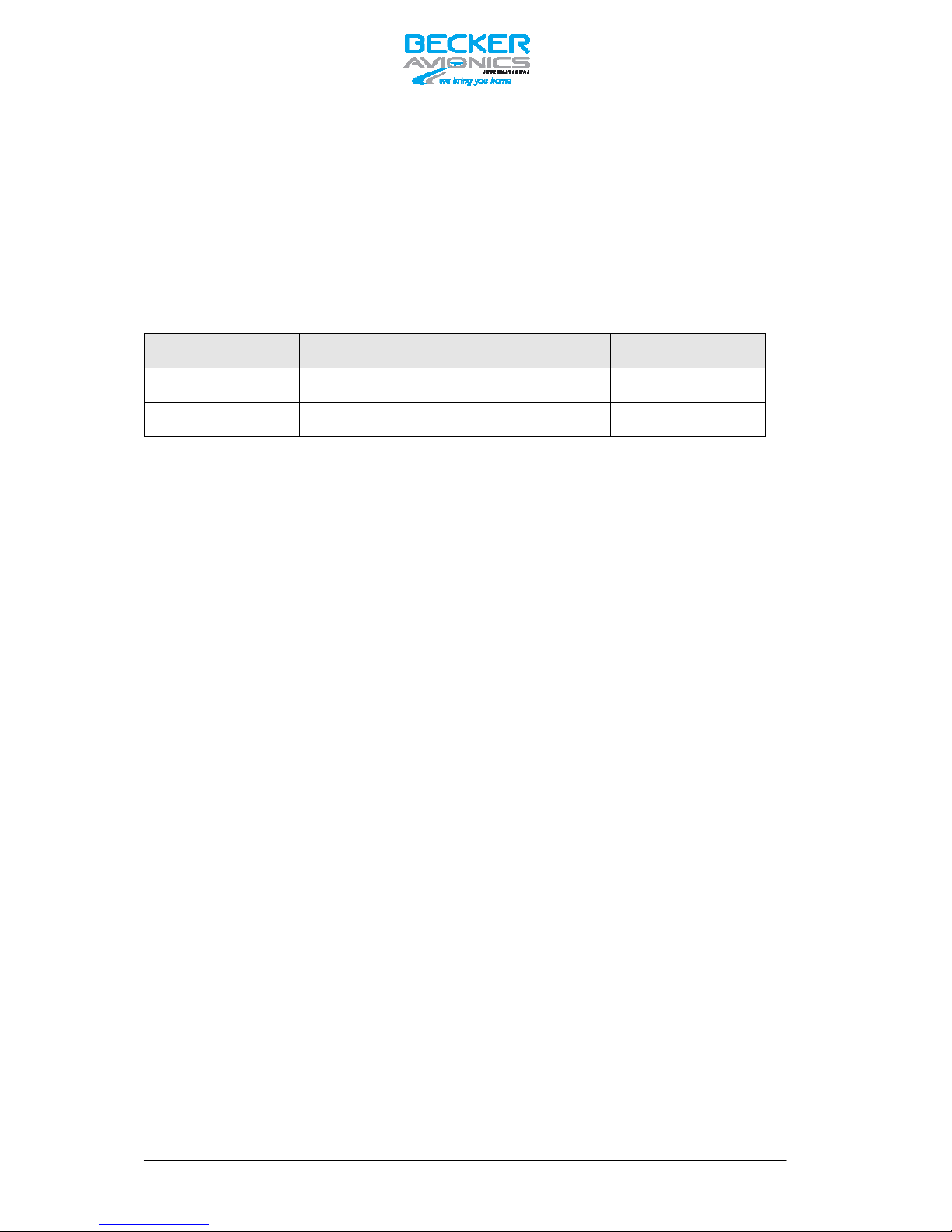
1.5 Variants survey
Part-Number:
Article Number Panel Color Display Color
AR6201-(000) 0610.321-910 black green
AR6201-(002) 0614.203-910 black blue / white
1.6 Technical data
1.6.1 Power supply data
Nominal supply voltage range 11.0 … 30.3 V DC
Abnormal supply voltage range 10.25 V … 32.2V DC
Emergency operation 9.0 V DC … 10.25 V DC (degraded performance)
Power consumption
Power off state ≤ 2.5 mA
Reception mode ≤ 140 mA @ 14 V DC, panel backlight off
Transmission mode ≤ 2 A @ 14 V DC, 70 % modulated, VSWR = 1:1
≤ 4 A @ 14 V DC; 70 % modulated, VSWR = 3:1
DC-Fuse internal 5 A (resettable)
Dimming control 14 V DC or 28 V DC
1.6.2 General data
Frequency range 118.000 MHz to 136.975 MHz (25 kHz mode)
Frequency range 118.000 MHz to 136.9916 MHz (8.33+25 kHz mode)
Channel spacing 25 kHz or 8.33 kHz
Number of channels 760 (25 kHz mode)
2280 + 760 (8.33+25 kHz mixed mode)
Storage temperature range -55 °C to +85 °C
Operating temperature range as per
EUROCAE/RTCA ED-14E/DO-160E -20 °C to + 55 °C
short-time + 70 °C
Operating altitude as per
EUROCAE/RTCA ED-14E/DO-160E 35,000 ft

AR6201
DV 14300.03/.04 Issue 2 10/2010 Page 1-5
Vibration as per
EUROCAE/RTCA ED-14E/DO-160E Category S (Curve M) + Category U (Curve G)
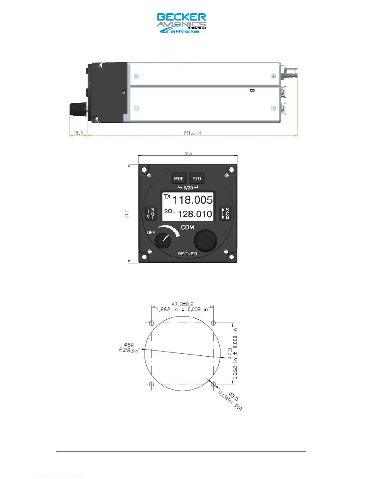
1.6.3 Dimensions & Weight
Front panel 61.2 mm x 61.2 mm
Depth of unit 211.4 mm (front plate till end of antenna connector)
Mounting (backpanel) standard 58 mm diameter (21/4 inch)
Material of Case ALMg
Surface treatment control head coated with black matt paint
Weight 850 g
1.6.4 Receiver data
Sensitivity ≤ -101 dBm for a (S+N)/N ratio of 6 dB (nominal)
≤ -93 dBm for a (S+N)/N ratio of 6 dB (qualified
under environmental conditions)
Effective bandwidth ≥ ± 2.78 kHz at the 6 dB points
(8.33 kHz channel) ≤ ± 7.37 kHz at the 60 dB points
Effective bandwidth ≥ ± 8 kHz at the 6 dB points
(25 kHz channel) ≥ ± 22 kHz at the 60 dB points
Squelch trigger level adjustable
AGC characteristic ≤ 6 dB in range -93 dBm to 0 dBm
Distortion m = 85% ≤ 15%
Audio frequency response ≤ 6 dB 350 Hz to 2500 Hz
relative to 1000 Hz ≥ 35 dB at 4000 Hz
Rated output for speaker operation ≥ 4 W into 4 Ω
Rated output power ≥ 300 mW into 150 Ω
for headphone operation ≥ 100 mW into 600 Ω
Audio auxiliary input 1 V to 8 V (adjustable) across 600 Ω ± 10%
1.6.5 Transmitter data
Output power ≥ 6 W into 50 Ω (with and without modulation)
Frequency tolerance ≤ 5 ppm
Duty cycle 1 minute (TX) : 4 minutes (RX)

AR6201
Page 1-6 DV 14300.03/.04 Issue 2 10/2010
Type of modulation A3E (amplitude modulation)
Modulation capability ≥ 70%
Distortion at 70% modulation ≤ 15%
Modulation bandwidth: ≤ 6 dB, 350 Hz to 2500 Hz
Dynamic microphone 1 … 20 mV compressor starting point, adjustable
(with compressor) Input balanced, 200 Ω
Input range up to 30 dB above compressor starting
point.
Standard microphone 10 … 1000 mV compressor starting point, adjustable
(with compressor) Input unbalanced, 150 Ω
Input range up to 30 dB above compressor starting
point.
FM deviation with modulation ≤ 3 kHz
Sidetone adjustable
Automatic shutdown of transmit mode 120 seconds
1.6.6 Software
Nearly all functions inside the transceiver are controlled by microprocessors. The software is
classified as Level D in accordance with EUROCAE/RTCA document ED12B/DO-178B.
1.6.7 Approval
ETSO EASA.210.1249
ETSO 2C37e
ETSO 2C38e
TSO pending

AR6201
DV 14300.03/.04 Issue 2 10/2010 Page 1-7
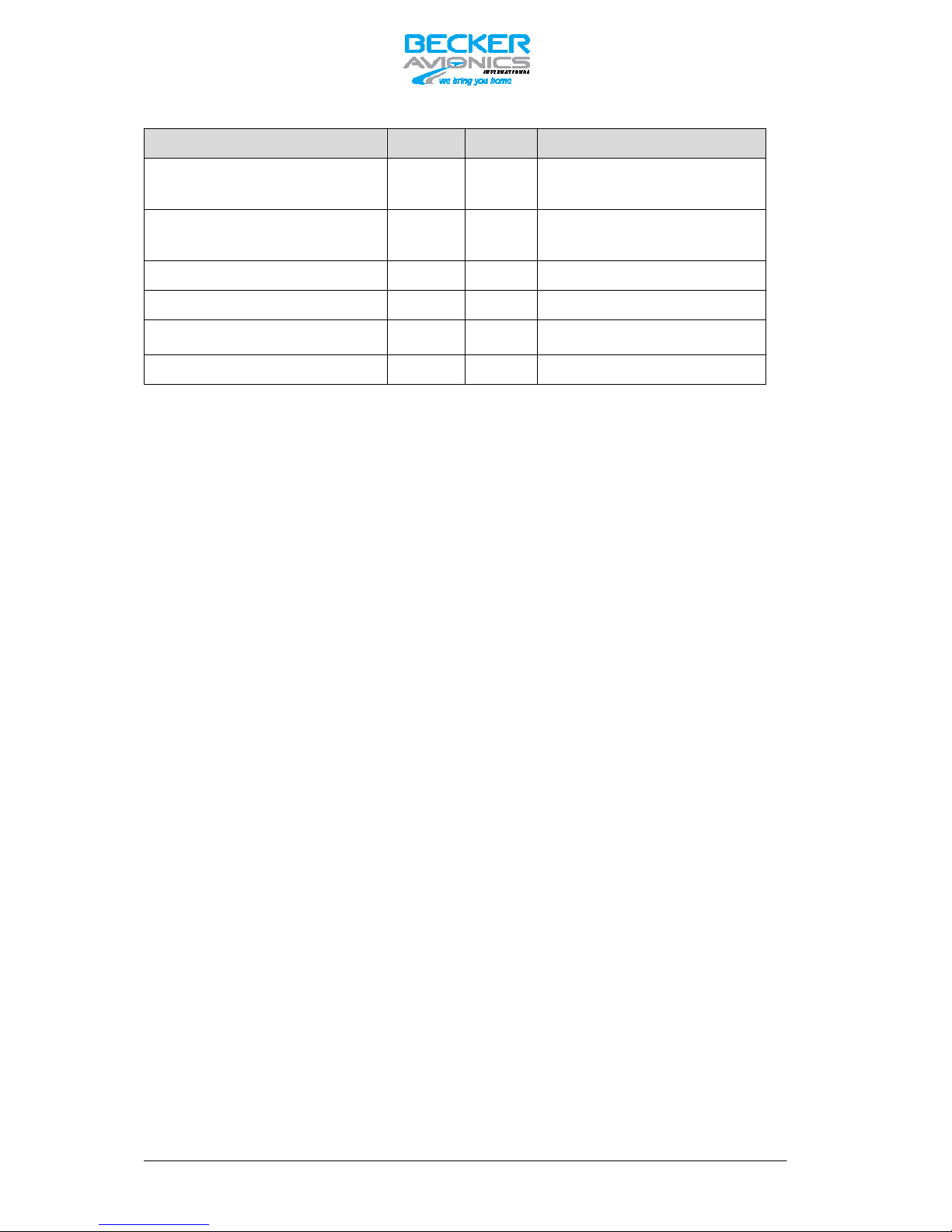
1.7 Environmental Qualification
The following performance under environmental test conditions have been established in
accordance with the procedures set forth in EUROCAE/RTCA Document ED-14E/DO-160E.
Condition Section Cat. Description
Temperature and Altitude 4.0 C4
Ground Survival Low Temperature 4.5.1 -55 deg C
Short-Time Operating Low
Temperature
-20 deg C
Operating Low Temperature -20 deg C
High Ground Survival Temperature 4.5.2 +85 deg C
High Short-Time Operating Temp. 4.5.3 +70 deg C
Operating High Temp. 4.5.4 +55 deg C
In-flight Loss of Cooling 4.5.5 X No forced cooling required
Altitude 4.6.1 C4 35,000 ft
Decompression 4.6.2
Overpressure 4.6.3
Temperature Variation 5.0 B 5°C per minute
Humidity 6.0 A Standard
Shock and Crash Safety 7.0 B
Fixed-wing and Helicopter,
standard
Vibration 8.0
S
U
Curve M for Fixed-wing Aircraft
Curve G for Helicopters
Explosion proofness 9.0 X N/A
Water proofness 10.0 X N/A
Fluids Susceptibility 11.0 X N/A
Sand and Dust 12.0 X N/A
Fungus Resistance 13.0 X N/A
Salt Spray 14.0 X N/A
Magnetic Effect 15.0 Z Less than 0.3m
Power Input 16.0 B
DC installations with battery of
significant capacity
Voltage Spike 17.0 A
High degree of protection against
voltage spikes
Audio Freq. Conducted
Susceptibility
18.0 B
DC installations with battery of
significant capacity
Induced Signal Susceptibility 19.0 AC Primary power DC or AC, 400Hz
Radio Frequency Susceptibility 20.0 SW
Interim High Intensity Radiated
Fields
AR6201
Page 1-8 DV 14300.03/.04 Issue 2 10/2010
Condition Section Cat. Description
Emission of Radio Frequency
Energy
21.0 B
Equipment where interference
should be controlled to a
tolerable level
Lightning Induced Transients
Susceptibility
22.0 A1E3X
Pin test waveform A, level 1
Cable bundle test waveform E,
level 3
Lightning Direct Effects 23.0 X N/A
Icing 24.0 X N/A
Electrostatic Discharge 25.0 A
Equipment operated in an
aerospace environment
Fire, Flammability 26.0 X N/A

AR6201
DV 14300.03/.04 Issue 2 10/2010 Page 1-9
1.8 Accessories
Connector Kit CK4201-S (soldering version) Article-No.: 0879.304-954
consisting of:
25-pol. cable connector, soldering F Article no. 0725.021-277
Connector housing Article no. 0775.479-277
Antenna plug Article no. 0725.706-277
Label “COMM” Article no. 0711.111-258
Connector Kit CK4201-C (crimp version) Article-No.: 0514.901-954
consisting of:
25-pol. cable connector, crimp F Article no. 0472.921-277
Connector housing Article no. 0775.479-277
Antenna plug Article no. 0725.706-277
Label “COMM” Article no. 0711.111-258
Connector Kit CK6200-S (soldering version) Article-No.: 0617.903-954
consisting of:
25-pol. cable connector, soldering F Article no. 0725.021-277
25-pol. cable connector, soldering M Article no. 0726.331.277
2 X Connector housing Article no. 0775.479-277
Antenna plug Article no. 0725.706-277
Label “COMM” Article no. 0711.111-258

AR6201
Page 1-10 DV 14300.03/.04 Issue 2 10/2010
Connector Kit CK6200-C (crimp version) Article-No.: 0617.891-954
consisting of:
25-pol. cable connector, crimp F Article no. 0472.921-277
25-pol. cable connector, crimp M Article no. 0891.551-277
2 X Connector housing Article no. 0775.479-277
Antenna plug Article no. 0725.706-277
Label “COMM” Article no. 0711.111-258
Documentation
Operating instructions Article no. 0618.764-071
Manual Installation and Operation Article no. 0617.857-071
Manual Maintenance and Repair Article no. 0617.865-071

AR6201
DV 14300.03/.04 Issue 2 10/2010 Page 2-I
Table of contents
Section 2 Installation Page
2.1 General 1
2.2 TestingbeforeInstallation 1
2.3 MechanicalInstallation 1
2.4 ElectricalInterface 3
2.4.1 ConnectorsandPinAssignment 3
2.4.2 Inputs/OutputsdetailedDescription 5
2.5 InstallationWiring 8
2.5.1 TypicalWiringforSingleSeaterGlider 9
2.5.2 TypicalWiringforSingleSeaterGlider(5‐polDIN
Jack) 10
2.5.3 TypicalWiringforTwinSeaterMotorGlider 11
2.5.4 TypicalWiringforusageofStandardHeadsets 12
2.5.5 TypicalWiringforAircraftswithIntercomSystem(Unbalanced) 13
2.5.6 TypicalWiringforAircraftswithIntercomSystem(Balanced) 14
2.6 Locationofinternalautomaticfuse 15
2.7 InstallationSetup
15
2.7.1 EnteringInstallationSetup 15
2.7.2 LeavingInstallationSetup 16
2.7.3 PageUp/PageDownintheInstallationSetup 16
2.7.4 StoringofSetupData 16
2.7.5 InstallationSetupPages–DataDescription 16
2.8 TypicalSettingsinInstallationSetup 22
2.8.1 SingleSeaterGlider 22
2.8.2 TwinSeater
MotorGlider 22
2.8.3 GAaircraftusingStandardMicrophones 22
2.9 RetrofittinganAR4201withanAR6201 23
2.9.1 PinCompatibility 23
2.9.2 DynamicMicrophoneInput 24
2.9.3 TemperatureSensor 25
2.9.4 RS‐232Interface 25
2.9.5 AFCU/AGC/AFWB 25
2.9.6 +13.75VSwitched 25
2.10 TestingafterInstallation 26
2.10.1 Ground
testwithengineshutdown 26
2.10.2 Groundtestwithenginerunning 26
2.11 ContinuedAirworthiness 26

AR6201
Page 2-II DV 14300.03/.04 Issue 2 10/2010
Blank

AR6201
DV 14300.03/.04 Issue 2 10/2010 Page 2-1
Section 2 INSTALLATION
2.1 General
The installation of the VHF transceiver depends on the type of aircraft and its equipment.
Therefore, only general information can be given in this section.
The VHF transceiver is designed as a single block unit for usage in cockpit environment of general
aviation aircrafts including helicopters under consideration of performed environmental qualification
(refer chapter 1.7) and SW Level (refer chapter 1.6.6). For guidance also refer AC23.1309.
Notice:
Changes or modifications made to this equipment not expressly approved in written form
by Becker Flugfunkwerk may void the authorization to operate this equipment.
2.2 Testing before Installation
General
Before installing the VHF transceiver in an aircraft, inspect the unit for marks of transport damage.
Visual examination
Before commissioning, visually examine the unit paying particular attention to the following:
(1) Dirt, dents, scratches, corrosion or broken attaching parts, damaged paintwork on housing,
parts of the housing and panel.
(2) Dirt or scratches on the identification plate, front panel, LCD or inscriptions.
(3) Dirt, bent or broken pins, displaced inserts of plugs and sockets.
(4) Dirt and mechanical damage to push buttons and operating knobs.
2.3 Mechanical Installation
The VHF transceiver is designed for installation in the instrument panel of an aircraft. It is
constructed for mounting from behind the panel by means of four screws, which are included in the
delivery. The circular cutout and the mounting holes are to be drilled in accordance with the
instrument size. The mounting point shall be at least 30 cm away from the aircraft magnetic
compass, to avoid any interference to the magnetic compass by the transceiver. The dimensions
are given in Figure 2-1.
AR6201
Page 2-2 DV 14300.03/.04 Issue 2 10/2010
Figure 2-1 Mounting dimensions VHF transceiver
Figure 2-2 Drilling jig for back-panel mounting
 Loading...