

Becker AR6201, RCU6201, RT6201, AR6203 Installation & Operation Manual
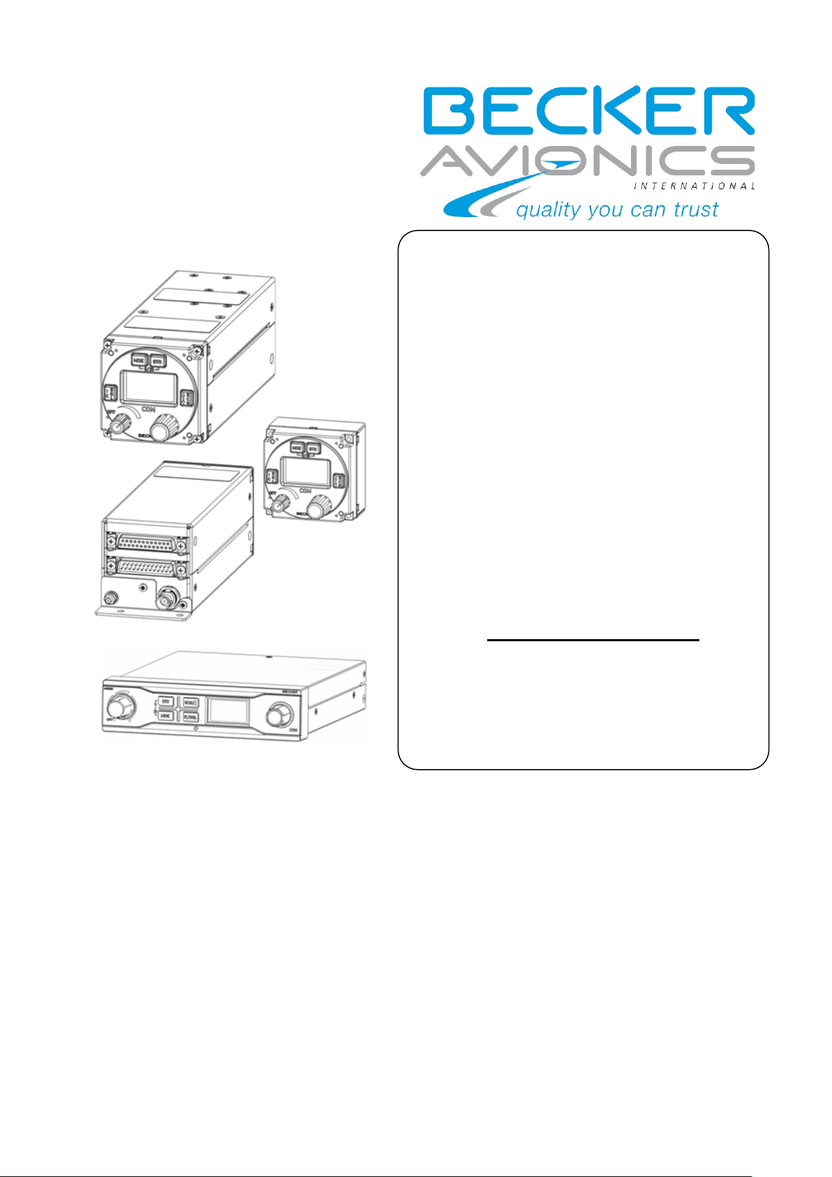
VHF-Transceiver
Family
AR6201-(X1X)
AR6201-(X2X)
RT6201-(X10)
RT6201-(X20)
RCU6201-(X1X)
AR6203-(X1X)
AR6203-(X2X)
Software Versions:
SCI1050S305 Version 3.07
SCI1051S305 Version 1.51
and upwards
AR6201
RCU6201
RT6201
AR6203
Becker Avionics GmbH ● Baden Airpark B108 ● 77836 Rheinmünster ● Germany
Telephone +49 (0) 7229 / 305-0 ● Fax +49 (0) 7229 / 305-217
http://www.becker-avionics.com ● e-mail: info@becker-avionics.de
Installation
Operation
Manual DV 14307.03
Issue 1 September 2013

FIRST ISSUE AND CHANGES
Issue 1 September 2013
LIST OF EFFECTIVE PAGES
Page No.: Date: Page No.: Date:
Cover Page
09/2013
I … VIII
09/2013
1-1 … 1-20 09/2013
2-1 … 2-66 09/2013
3-1 … 3-20 09/2013
DV 14307.03 / Article Number 0638.404-071
© 2013 by Becker Avionics GmbH / All rights reserved


AR6201 - RT6201 - RCU6201 - AR6203
Preface
Dear Customer,
Thank you for purchasing BECKER products.
We are pleased that you have chosen our product and we are confident
that it will meet your expectations.
AR620X-(XXX) VHF Transceivers are a modern family of communication
equipment that have comprehensive capabilities and significantly extend
the typical aeronautical transceivers.
Despite its small size and weight 620X- aircraft radio include inter
alia:
• Sensitive receiver which meets the most recent requirements of ED23C, including the ability to work in the offset-carrier (climax)
operation in 25 kHz and 8.33 kHz channel spacing (class H2).
• Receiver that includes SCAN (dual watch) mode. This allows
simultaneous monitoring of two different VHF frequency channels
without interrupting communication on the active frequency.
• High efficiency transmitter which delivers more than 10W modulated or
un-modulated output power at 28V supply voltage or 6W at 12V. Low
power consumption allows longer operation from battery.
• Extended built-in intercom which can work as:
o 4-way intercom with isolation mode – passengers could continue
conversation or listening to music from MP3 player at the same
time as pilots talk via intercom or communicate with the tower.
o 2-way intercom for tandem operation – pilot and co-pilot work
with separate controllers and can control their individual
audio parameters, like volume or VOX. This mode is preferred
especially for training due to full synchronization of LCD
contents.
• Non-volatile memory for storing:
o 99 VHF channels can manually be labeled for storage of VHF
channels
o 9 recently selected VHF channels are automatically stored
DV 14307.03 Issue 1 09/2013 Page I

AR6201 - RT6201 - RCU6201 - AR6203
Table of Contents
List of Abbreviations VI
Section 1 GENERAL DESCRIPTION 1-1
1.1 Introduction 1-1
1.2 Purpose of Equipment 1-1
1.3 General Notes 1-2
1.4 Variants Overview 1-2
1.5 Short Description 1-3
1.5.1 AR6201 Single Block Transceiver 1-4
1.5.2 RT6201 Remote Transceiver 1-4
1.5.3 RCU6201 Remote Control Unit 1-5
1.5.4 AR6203 Single Block Transceiver 1-6
1.6 Features Overview 1-6
1.7 Technical Data 1-9
1.7.1 Power Supply Data 1-9
1.7.2 General Data 1-10
1.7.3 Dimensions & Weight 1-11
1.7.4 Receiver Data for AR620X and RT6201 1-11
1.7.5 Transmitter Data AR620X and RT6201 1-12
1.7.6 Emergency Operation 1-12
1.7.7 Software 1-13
1.7.8 Complex Hardware 1-13
1.7.9 Regulatory Compliance 1-13
1.8 Environmental Qualification AR620X and RCU6201 1-14
1.9 Environmental Qualification RT6201 1-16
1.10 Accessories 1-18
Page II DV 14307.03 Issue 1 09/2013

AR6201 - RT6201 - RCU6201 - AR6203
Section 2 INSTALLATION 2-1
2.1 Limitations 2-1
2.2 Unpacking the Equipment and Preparation for
Installation 2-1
2.3 Mechanical Installation 2-1
2.3.1 AR6201 and RCU6201 Installation 2-1
2.3.2 AR6203 Installation 2-3
2.3.3 RT6201 Installation 2-5
2.4 Electrical Interface 2-8
2.4.1 Connectors and Pin Assignment for AR6201, AR6203
and RT6201 2-8
2.4.2 Inputs / Outputs Detailed Description 2-11
2.4.3 Connector and Pin Assignment for RCU6201 2-16
2.5 Installation and Configuration of 620X Transceivers 2-17
2.6 Antenna Installation 2-18
2.7 Installation Setup for RT/AR6201-(X1X) 2-19
2.7.1 Entering Installation Setup 2-19
2.7.2 Leaving Installation Setup 2-19
2.7.3 Page Up / Page Down in the Installation Setup 2-19
2.7.4 Storage of Setup Data 2-19
2.7.5 Terminate Installation Setup 2-19
2.7.6 VU Meter 2-20
2.7.7 Installation Setup Pages - Data Description 2-20
2.8 Factory Default Settings 2-35
2.9 Typical Installations with Recommended Settings and
Wiring Diagrams 2-37
2.9.1 Single Seat Glider 2-37
2.9.2 Twin Seat Motor Glider 2-40
2.9.3 General Aviation (GA) Aircraft using Standard
Microphones 2-42
2.9.4 Installation Setup for individual dual headset
configuration (two IC circuit) 2-44
DV 14307.03 Issue 1 09/2013 Page III

AR6201 - RT6201 - RCU6201 - AR6203
2.9.5 Installation Setup for Twin Seat with AR6201 Tandem
Configuration 2-46
2.9.6 Wiring for Aircraft with Four Seats (no TANDEM) 2-48
2.9.7 Installation with RT6201 2-51
2.9.8 Aircraft with Intercom System 2-52
2.9.9 Installation Setup for Twin Seat with RT6201 Tandem
Configuration 2-55
2.10 Retrofitting an AR4201 with an AR620X 2-57
2.10.1 Pin Compatibility 2-57
2.10.2 Dynamic Microphone Input 2-59
2.10.3 Temperature Sensor 2-59
2.10.4 RS-232 Interface 2-59
2.10.5 AFCU/AGC/AFWB 2-60
2.10.6 CPIN 2-60
2.10.7 +13.75V Switched 2-60
2.10.8 PWR_EVAL 2-60
2.11 Post Installation Tests 2-60
2.11.1 Mechanical Installation and Wiring Check 2-60
2.11.2 Power Supply 2-60
2.11.3 Receiver / Transmitter Operation 2-61
2.11.4 Antenna Check 2-61
2.11.5 Interference Check 2-61
2.11.6 Flight Test Check 2-63
2.12 Trouble Shooting 2-63
2.13 Continued Airworthiness 2-65
Page IV DV 14307.03 Issue 1 09/2013

AR6201 - RT6201 - RCU6201 - AR6203
Section 3 OPERATION 3-1
3.1 Safety Instructions 3-1
3.2 Controls and Indicators 3-2
3.2.1 Controls 3-2
3.2.2 Symbols Shown on the Display 3-3
3.3 Start-Up 3-3
3.4 Receive and Transmit Mode 3-4
3.4.1 Receive Mode 3-4
3.4.2 Transmit Mode 3-4
3.5 Frequency Selection Modes 3-5
3.5.1 Standard Mode 3-5
3.5.2 Direct Tune Mode 3-6
3.5.3 Channel Mode 3-7
3.5.4 Scan Mode 3-9
3.6 Squelch 3-10
3.7 RX Field Strength Indication 3-10
3.8 Channel Spacing Mode 3-11
3.9 Storage Function 3-11
3.9.1 Manual Storage Function 3-11
3.9.2 Automatic Storage Function 3-13
3.10 Auxiliary Audio Input 3-13
3.11 Intercom Operation 3-13
3.12 VOX & Speaker Operation 3-15
3.13 Menus 3-15
3.13.1 Intercom Menu 3-15
3.13.2 Pilots Menu 3-17
3.14 Warning and Failure Indications 3-18
DV 14307.03 Issue 1 09/2013 Page V

AR6201 - RT6201 - RCU6201 - AR6203
List of Abbreviations
AC ..... Alternating Current
AF ..... Audio Frequency
AR ..... Airborne Radio
ATT .... Attenuation
AUX .... Auxiliary
AWG .... American Wire Gauge
BNC .... Bayonet Neill Concelman
CBIT ... Continuous Built-In Test
CFG .... Configuration
CH ..... Channel
CM ..... Chassis Module
COM .... Communication
DC ..... Direct Current
EASA ... European Aviation Safety Agency
EMI .... Electro Magnetic Interference
ETSO ... European Transmission System Operators
GND .... Ground (Aircraft Ground)
GPS .... Global Positioning System
HMI .... Human Machinery Interface
HIRF ... High Intensity Radiated Fields
IC ..... Intercom
I&O .... Installation & Operation
LCD .... Liquid Crystal Display
MFD .... Multi-Function Display
M&R .... Maintenance & Repair
N/A .... Not Applicable
NAV .... Navigation
PBIT ... Power-On Built In Test
PTT .... Push To Talk
PWR .... Power
RCU .... Remote control unit
Page VI DV 14307.03 Issue 1 09/2013

AR6201 - RT6201 - RCU6201 - AR6203
RSSI ... Received Signal Strings Indication
RT ..... Remote Transceiver
RX ..... Receive
SQL .... Squelch
SPKR ... Speaker (Loudspeaker)
SRC .... Source
SW ..... Software
TSO .... Technical Standard Order
TX ..... Transmit
VOX .... Voice Operated IC Threshold
VHF .... Very High Frequency
VDC .... Voltage Direct Current
VSWR ... Voltage Standing Wave Ratio
VU ..... Volume Unit
Units
V ...... Volt
mV ..... Millivolt
A ...... Ampere
mA ..... Milliampere
W ...... Watt
mW ..... Milliwatt
kHz .... Kilohertz
MHz .... Megahertz
s ..... Second
dBm .... Power ratio in decibels
dB ..... Decibel
Ohm(Ω) . Resistor
kg ..... Kilogram
t ...... Tons
°C ..... Degree Celsius
mm ..... Millimeter
cm ..... Centimeter
DV 14307.03 Issue 1 09/2013 Page VII

AR6201 - RT6201 - RCU6201 - AR6203
Blank
Page VIII DV 14307.03 Issue 1 09/2013
AR6201 - RT6201 - RCU6201 - AR6203
Section 1 GENERAL DESCRIPTION
1.1 Introduction This manual describes the operation and installation of the
RCU/RT/AR6201 VHF Transceiver Family equipment. The ID label on your
device shows the part number for identification purposes.
Before starting to operate the unit(s) please rea d this manual carefully
with particular attention to the description referring to your
device(s). This manual also contains several optional elements of the
system (second controller for example), that may not be contained in
your delivery package and in that case are not applicable.
For simplification of this document the short version “620X” for VHF
transceivers and “RCU6201” for the remote controllers will be used
instead of the full part number identification.
The manuals DV 14307.03 I&O (“Installation and Operation”) and DV
14307.04
M&R (“Maintenance and Repair”) contain the following sections:
Section
1 General
2 Installation
3 Operation
4 Theory of Operation
5 Maintenance and Repair
6 Illustrated Parts List
7 Modification and Changes
8 Circuit Diagrams
DV 14307.03
I&O
X X
X X
X X
N/A X
N/A X
N/A X
N/A X
N/A X
DV 14307.04
M&R
1.2 Purpose of Equipment The 620X transceivers enable voice communication between aircrafts or
between aircraft and ground using the very high frequency band between
118.000 to 136.9916 MHz respectiv ely 136.9750 with a selectable c hannel
spacing of 25 kHz respectively 8.33 kHz. The wide scope of accessories
also allows usage of the 620X VHF transceivers in ground-based
applications.
DV 14307.03 Issue 1 09/2013 Page 1-1

Part Number
Article No
8.33kHz Mode
Transmit PWR
AR6201 - RT6201 - RCU6201 - AR6203
The 620X-(XXX) Transceiver Family is dedicated to applicatio ns where low
power consumption is required. They are capable to operate from standar d
14 VDC and 28 VDC installations and from 12 VDC or 24 VDC batteries.
Ultra low power consumption with extrem ely wide DC supply voltage range
as well as compact and lightweight desig n allows application for glider s
and leisure aircraft up to 2000 kg and balloons.
Built-in 4-seat configurable intercom, transmitter output power up to
10W and option for connection of two controllers in tandem
configurations extends the flexibility of 620X VHF transceivers.
The 620X transceivers also provide additional options such as:
• Intercom functional ity for voice commun ication between aircraft crew
and passengers
• Squelch functionali ty that automaticall y mutes receiver audio signal
until clear signal is received to avoid unwanted audio noise
• Scan functionality for simultaneous monitoring of two VHF channels
(receive mode)
• AUX audio input for connection of additional audio devices like
navigation receiver, warning tone generator or MP3 music player.
• VHF channel database for easy access to predefined frequency channels
• Tandem functionality for synchronized operation of two controllers
1.3 General Notes In this document the word “frequency” is also used in the sense of
“channel name”, as defined in EUROCAE, ED-23B: chapter 1.3.2.
In this document the word “memory channel” or “channel” means a memory
place identified by a channel number, where a frequency may be stored
for later use.
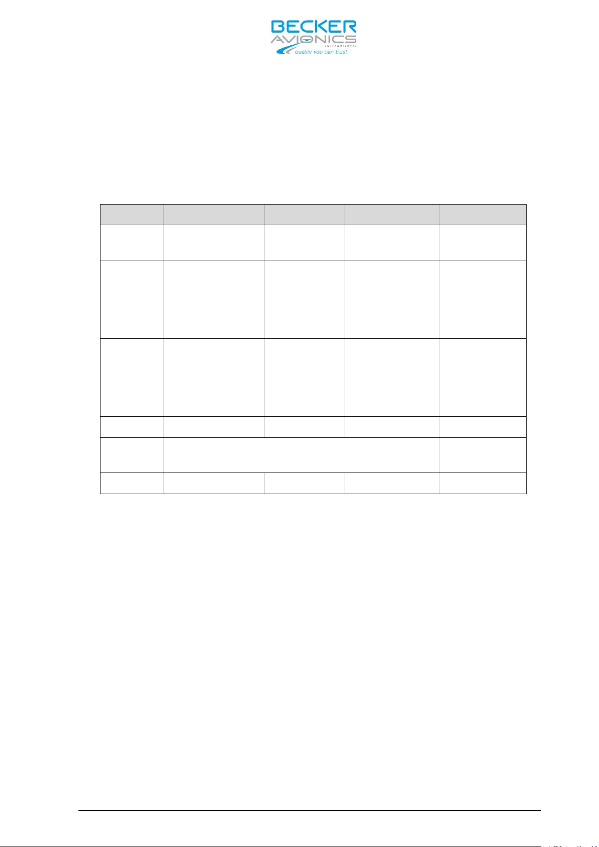
1.4 Variants Overview Within the part number, the meaning of “- (XXX)” is:
(0XX) indicates 8.33/25 kHz channel spacing capability
(1XX) indicates only 25 kHz channel spacing capability
(X1X) indicates transmit power 10W at 28V
(X2X) indicates transmit power 6W at 12V
(XX2) indicates white illumination color on a black panel
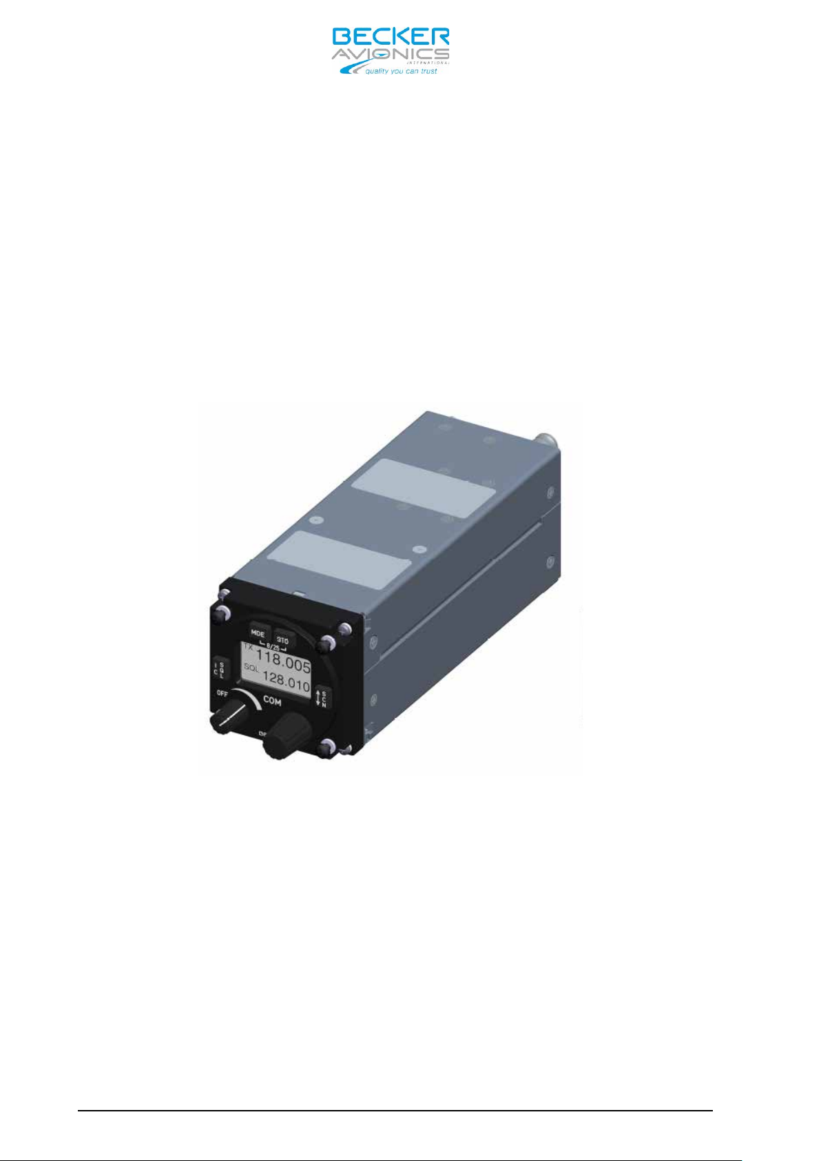
AR6201 Single Block Transceiver (refer to Figure 1-1)
Page 1-2 DV 14307.03 Issue 1 09/2013
AR6201-(012) 0631.418-910 yes 10W at 28V
AR6201-(112) 0631.434-910 no 10W at 28V
Part Number
Article No
8.33kHz Mode
Transmit PWR
Part Number
Article No
8.33kHz Mode
Transmit PWR
Part Number
Article No
8.33kHz Mode
Transmit PWR
Part Number
Article No
8.33kHz Mode
Transmit PWR
AR6201 - RT6201 - RCU6201 - AR6203
AR6201-(022) 0636.339-910 yes 6W at 12V
AR6201-(122) 0636.355-910 no 6W at 12V
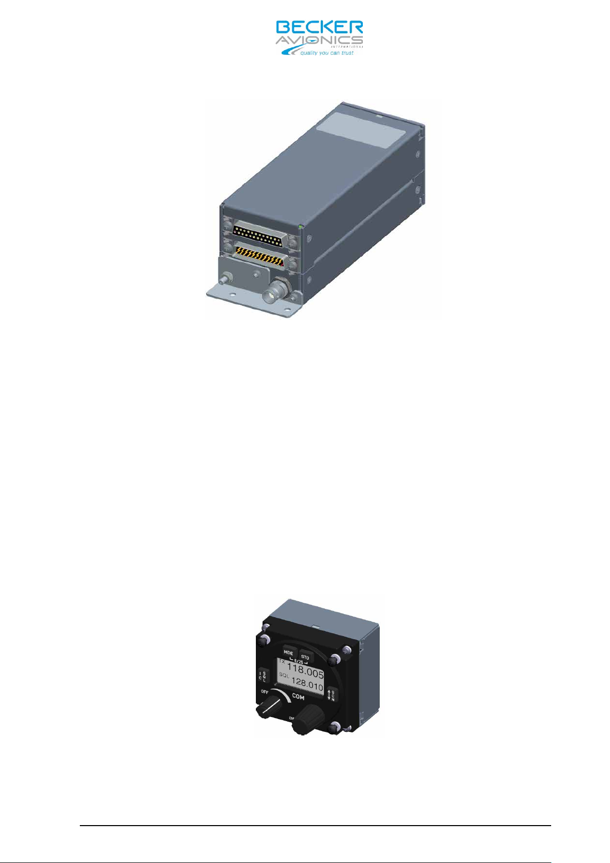
RT6201 Remote Transceiver (refer to Figure 1-2)
RT6201-(010) 0631.442-910 yes 10W at 28V
RT6201-(020) 0636.312-910 yes 6W at 12V
RT6201–(110) 0638.609-910 yes 10W at 28V
RT6201-(120) 0638.617-910 yes 6W at 12V
RCU6201 Remote Control Unit (refer to Figure 1-3)
RCU6201-(012) 0631.469-910
RCU6201-(112) 0631.485-910
yes
no
AR6203 Single Block Transceiver (refer to Figure 1-4)
AR6203-(012) 0630.993-910 yes 10W at 28V
AR6203-(112) 0631.566-910 no 10W at 28V
AR6203-(022) 0636.371-910 yes 6W at 12V
AR6203-(122) 0636.398-910 no 6W at 12V
1.5 Short Description
For Single Configuration the Following Combinations apply:
• AR6201 or AR6203 Single Block Transceiver
• RT6201 Remote VHF Transceiver with controller RCU6201
N/A
N/A
For Tandem Configuration the Following Combinations apply:
DV 14307.03 Issue 1 09/2013 Page 1-3
• AR6201 or AR6203 S ingle Block Transceiver with additional controller
RCU6201
• RT6201 Remote VHF Transceiver wi th controller RCU6201 and additional
second controller RCU6201
In tandem configuration two controllers and one transceiver are
connected. Tandem configuration is useful for training purposes where
AR6201 - RT6201 - RCU6201 - AR6203
pilot and student have their own controller with full-synchr onized views
or as separate controllers for pilot and co-pilot.
1.5.1 AR6201 Single Block Transceiver The AR6201 Single Block Transceiver is a compact and lightweight unit
designed for operation in a cockpit environment for both general
aviation aircraft and helicopters. The dimensions correspond to the
standard instrument diameter of 58 mm (2 ¼ inch). All controls and
indicators are located on the front panel.
The equipment connectors and the a ntenna socket are located at the rear
of the units.
The AR6201 should be mounted by means of four screws (rear panel
installation).
Figure 1-1: AR6201 Single Blo ck Transceiver; 58 mm (2 ¼ inch)
standard instrument cut-out
1.5.2 RT6201 Remote Transceiver The RT6201 Remote Transceiver is a compact and lightweight single block
unit in rectangular shape that contains a VHF transceiver. The
dimensions correspond to the stand ard instrument diameter of 58 mm (2 ¼
inch).
The RT6201 Remote Transceiver can be controlled via its dedicated
controller RCU6201 or by a third party controller via MFD (BECKER
proprietary protocol required).
Page 1-4 DV 14307.03 Issue 1 09/2013
AR6201 - RT6201 - RCU6201 - AR6203
Figure 1-2: RT6201 Remote Single Block VHF transceiver,
back panel installation
The RT6201 Remote Transceiver is installed by means of the attached
mounting provisions and four screws (back panel installation).
1.5.3 RCU6201 Remote Control Unit The RCU6201 Remote Control Unit is a compact and lightweight unit. The
dimensions correspond to the stand ard instrument diameter of 58 mm (2 ¼
inch).
All controls and indicators are located on the front panel. The
equipment connectors are located at the rear of the units.
The controller RCU6201 should be mounted with four screws (rear panel
installation).
Figure 1-3: RCU6201 Remote Control Unit; 58 mm (2 ¼ inch)
standard instrument cut-out
DV 14307.03 Issue 1 09/2013 Page 1-5
AR6201 - RT6201 - RCU6201 - AR6203
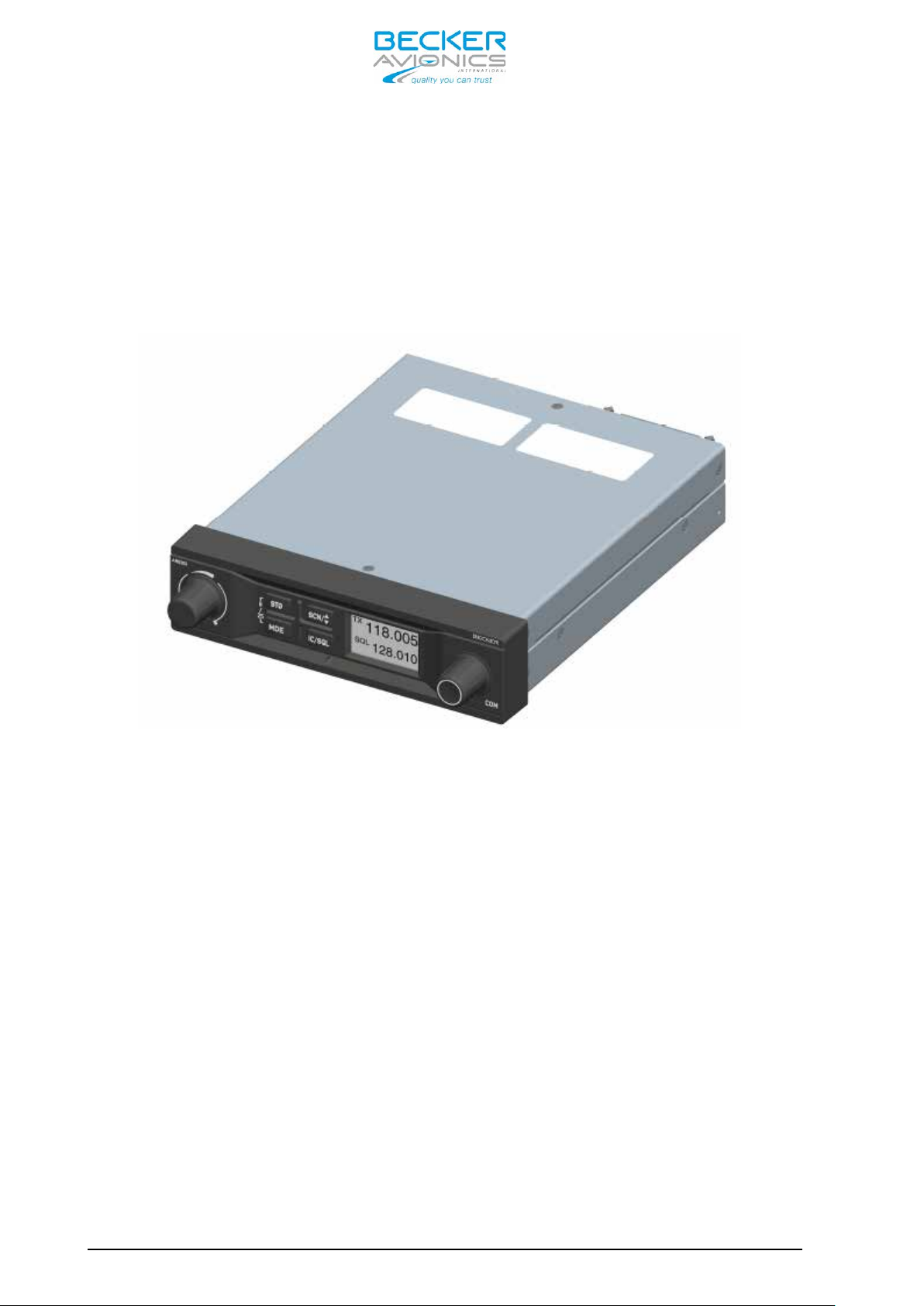
1.5.4 AR6203 Single Block Transceiver The AR6203 Single Block Transceiver is designed as a single block unit.
AR6203 is designed for operation in a cockpit environment for both
general aviation aircraft and helicopters. The dimensions correspond to
state-of-the-art 160mm (6.3 “) panel mounted design.
the
Figure 1-4: AR6203 Single Block Transceiver
All control elements are located on the front panel of the unit. For
connection to the aircraft inter-wiring two 25-pin unit connectors and
BNC antenna socket are located at the rear of the unit.
The AR6203 should be mounted with the designated mounting kit MK6403-1
(refer to chapter 1.10). Six holes on both sides of the mounting kit
frame enable the device to be mounted in the aircraft cockpit.
1.6 Features Overview
Frequency Indication
A liquid crystal display (LCD) provides the frequency indication. The
required operating frequency is set with the rotary knob. The relation
between the real operating frequency and the displayed frequency is
according to standards (ED-23B, chapter 1.3.2). For an overview, refer
to the table below.
Page 1-6 DV 14307.03 Issue 1 09/2013
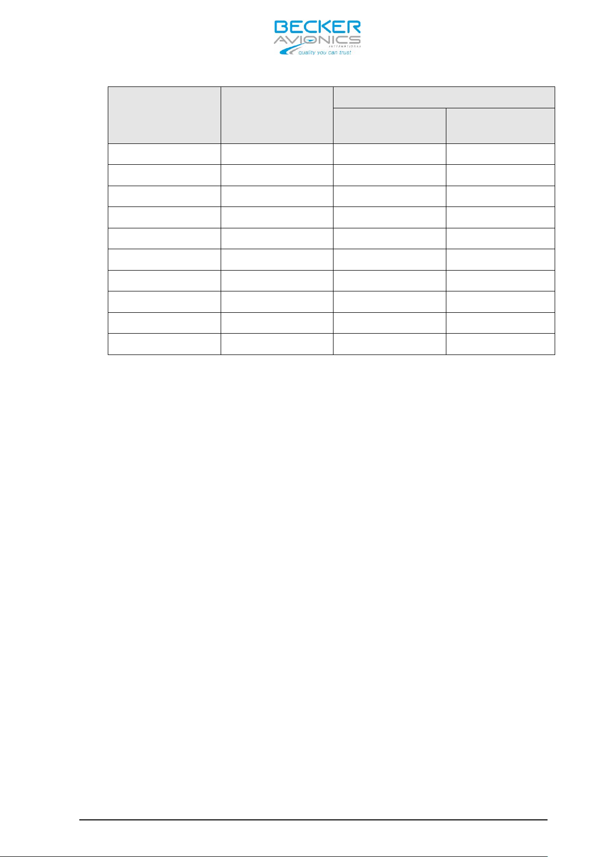
Operating
Frequency
(MHz)
Channel
Spacing
(kHz)
Displayed Frequency
8.33 + 25 kHz
mixed Mode
25 kHz only
Mode
AR6201 - RT6201 - RCU6201 - AR6203
118.0000 25 118.000 118.00
118.0000 8.33 118.005 N/A
118.0083 8.33 118.010 N/A
118.0166 8.33 118.015 N/A
118.0250 25 118.025 118.02
etc. etc. etc. etc.
136.9750 25 136.975 136.97
136.9750 8.33 136.980 N/A
136.9833 8.33 136.985 N/A
136.9916 8.33 136.990 N/A
Audio Outputs
The 620X VHF Transceiver includes four fully configurable outputs:
• Headphone 1 output, rated output power is 300 mW into 75 Ohm.
• Headphone 2 output, rated output power is 200 mW into 75 Ohm.
• Speaker output, rated output power is 4 W into 4 Ohm.
• LINE-OUT output intended for ground station use only
Note: Headphone 2 and speaker output cannot be active at the same time
Mike Inputs
The VHF transceiver has an input for dynamic microphone (DYN_MIKE) and
an input for standard microphone (STD_MIKE).
The 620X VHF Transceiver provides four microphone inputs:
• standard microphone input 1 (STD_MIKE1)
• standard microphone input 2 (STD_MIKE2)
• standard microphone input 3 (STD_MIKE3)
• dynamic microphone input (DYN_MIKE)
Each input is able to operate with one single microphone or with two
microphones of the same type connected in parallel.
AF Auxiliary Input
The AF auxiliary provides the interface to connect an external audio
source (e.g. NAV, music-player) to the transceiver. Interconnection of
multiple external audio sources on this particular port requires
DV 14307.03 Issue 1 09/2013 Page 1-7

AR6201 - RT6201 - RCU6201 - AR6203
additional external decupling/isolation resistors. The external audio is
audible only when the transceiver is in receive mode.
The individual audio volume is set directly at the particular external
equipment.
Sidetone
The sidetone is available on the headphone output during transmission.
The sidetone volume automatically adapts to the intercom volume setting.
Squelch Operation
When enabled the squelch (muting) circuit suppresses weak si gnals. There
are two kinds of squelch methods implem ented: carrier squelch and noise
squelch. The carrier squelch depends on received signal strength and is
adjustable in the installation setup; the noise squelch depends on
detected noise level and is adjustable in the pilot setup.
Memory Channels
The memory function allows storage of up to 99+9 frequencies. This
memory may contain up to 99 frequencies stored manually or programmed
from PC that can be labeled with VHF channel numbers or assigned text
label. Additionally the last recently used (active) 9 frequencies are
stored automatically as “LAST” channels. A user defined text label can
also be assigned for each stored frequency.
Intercom Operation
Aircraft internal communication via connected headsets is provided by
the built-in intercom circuit. The 620X has two intercom circuits:
“Front row” and “Back row”. A maximum of four headsets can be connected
(for example pilot & copilot on first circuit and two passengers on
second circuit).
Scan Mode
In scan mode a dual watch function is provided. T he device is capable of
monitoring frequencies on two channels, active & preset simultaneously.
The signal of the active frequenc y will always b e audible, since it will
have priority at all times.
Tandem operation
Tandem mode enables operation of two controllers simultaneously. The
controllers are synchronized, so that both display the same information
Illumination
The illumination of LCD and push buttons can be controlled either
directly from the front panel via the pilots menu or externally via the
dimming input lines. If the external dimming is selected, the
Page 1-8 DV 14307.03 Issue 1 09/2013

AR6201 - RT6201 - RCU6201 - AR6203
illumination curve (brightness to voltage relation) can be adjusted in
the installation setup.
LOW BATT Indication
The VHF transceiver monitors power suppl y voltage. If the supply voltag e
drops below the adjustable threshold, the display indicates the message
“LOW BATT”. If the power supply voltage drops further, emergency
operation mode is entered.
Emergency Operation
If the power supply voltage drops below 10.25 V, the VHF transceiver
continues operation with degraded perf ormance. In case the power supply
drops below 9.0V the unit is automatically switched off.
Built-in Tests PBIT and CBIT
After power-up, the unit performs a se lf-test (power-up built-in test /
PBIT). During PBIT the transceiver displays “WAIT” and the correspo nding
software versions of both the control head and chassis module.
If faults are detected during PBIT, the error message “FAILURE press an y
key” is displayed. If no faults are detected the transceiver
automatically activates the mode set before last power-off.
During normal operation a continuous built-in test (CBIT) permanently
verifies the correct operation of the unit. If a problem is detected
during CBIT, an error message will be displayed.
Installation Setup
Configuration of the installation parameters such as mike sensitivity,
mike type selection, speaker enable/disable plus other parameters are
available via the installation setup.
Service Mode
The service mode is a special configuration mode accessible via RS422
interface with a proprietary serial data communication protocol. This
mode is for use by authorized maintena nce organizations during aircraft
service on ground only.
1.7 Technical Data
1.7.1 Power Supply Data For 620X units the following data applies:
Nominal supply voltage range .... 11.0 … 30.3 V
extended supply voltage range ... 10.25 V … 32.2V
Emergency operation ............. 9.0 V to 10.25 V
Dimming control ................. 0…14 V or 0…28 V
DV 14307.03 Issue 1 09/2013 Page 1-9

6W
10W
6W
10W
1.8A at
1.5A at
1.8A at
1.5A at
1.2A at
1.0A at
1.2A at
1.0A at
A at
1.0A at
AR6201 - RT6201 - RCU6201 - AR6203
Typical Power Consumption
Power “off” @ 12 VDC
Power “off” @ 27.5 VDC
Reception stand-by mode
@ 13.75 VDC, panel backlight
off
Reception stand-by mode
@ 27,5 VDC, panel backlight
off
Transmit mode
@ 13,75 VDC, VSWR=1:1
AR620X
(X2X)
≤ 0.10
mA
≤ 0.10
mA
≤ 140 mA ≤ 140 mA ≤ 120 mA ≤ 120 mA ≤ 20 mA
≤ 80 mA ≤ 80 mA ≤ 80 mA ≤ 80 mA ≤ 20 mA
70%
0%
AR620X
(X1X)
≤ 0.10
mA
≤ 0.10
mA
-
RT6201
(X2X)
≤ 0.10
mA
≤ 0.10
mA
70%
0%
RT6201
(X1X)
≤ 0.10
mA
≤ 0.10
mA
- ≤ 20 mA
RCU6201
≤ 0.10
≤ 0.10
(XXX)
mA
mA
1.4A at
Transmit mode
@ 27.5 VDC, VSWR=1:1
Absolute maximum current
@ 13.75 VDC, VSWR=3:1
Absolute maximum current
@ 27.5 VDC, VSWR=3:1
1.7.2 General Data For 620X units the following data apply:
Frequency range ............... 118.000 MHz to 136.975 MHz (-1XX model)
118.000 MHz to 136.9916 MHz (-0XX model)
Channel spacing ............... 25 kHz (-1XX model)
8.33/25 kHz (-0XX model)
Number of channels ............ 760 (-1XX model)
70%
0%
≤ 3A - ≤ 2,9A -
≤ 2A ≤ 2.5A ≤ 1.9A ≤ 2.4A
70%
1.0A at
0%
70%
0%
1.4
70%
0%
≤ 20 mA
≤ 20 mA
≤ 20 mA
2280 + 760 (-0XX model)
Page 1-10 DV 14307.03 Issue 1 09/2013
158.8mm
(front plate
Mounting Kit
AR6201 - RT6201 - RCU6201 - AR6203
Storage Temperature range ... -55°C to +85°C
Operating Temperature range .. -20°C to +55°C AR620X-(XXX) and RCU6201-(XXX)
-40°C to +55°C RT6201-(XXX)
short-time +70°C (all versions)
Operating Altitude ........... 35,000 ft
Vibration ................... Category S (Curve M) + Category U (Curve G)
1.7.3 Dimensions & Weight AR6201-(XXX) AR6203-(XXX) RCU6201-(XXX) RT6201-(XXX) Front
panel
Depth of
unit
Mounting
Material AlMg AlMg/Plastic AlMg AlMg
Surface
treatment
Weight 675g 850g 150g 600g
1.7.4 Receiver Data for AR620X and RT6201
61.2mm
x 61.2 mm
187.8 mm
(front plate to
end of antenna
connector)
(back panel)
standard
58 mm diameter
(2¼ inch)
Control-head coated with black matt paint
x 41.2 mm
207 mm
to end of
antenna
connector)
MK6403-1
61.2 mm
x 61.2 mm
39.3 mm 188 mm
(back panel)
standard
58 mm diameter
(2¼ inch)
61 mm
x 61 mm
Mounting Kit
MK6201-(010)
or directly
on avionic
bay
Sensitivity ..................... ≤ -101 dBm for a (S+N)/N ratio of 6 dB
(nominal)
................................ ≤ -93 dBm for a (S+N)/N ratio of 6 dB
(qualified under environmental conditions)
Effective bandwidth ............. ≥ ± 2.78 kHz at the 6 dB points
(8.33 kHz channel spacing) ≤ ± 7.37 kHz at the 60 dB points
Effective bandwidth ............. ≥ ± 8 kHz at the 6 dB points
(25 kHz channel spacing) ≤ ± 22 kHz at the 60 dB points
Squelch ........................ level adjustable
AGC characteristic .............. ≤ 6 dB in range -93 dBm to 0 dBm
Distortion ...................... ≤ 15% at 30% 10dB below rated output power
≤ 15% at 70% and rated output power
Audio frequency response ........ ≤ 6 dB 350 Hz to 2500 Hz
(8.33 kHz channel spacing) ≥ 35 dB at 4000 Hz
Audio Noise ..................... ≤ 6 dB 300 Hz to 3400 Hz
≥ 18 dB at 4000 Hz
DV 14307.03 Issue 1 09/2013 Page 1-11

AR6201 - RT6201 - RCU6201 - AR6203
Rated output for speaker operation .. ≥ 4 W into 4 Ohm
Rated output power for headphone 1 .. ≥ 300 mW into 75 Ohm
≥ 100 mW into 600 Ohm
Rated output power for headphone 2 .. ≥ 200 mW into 75 Ohm
≥ 100 mW into 600 Ohm
Audio auxiliary input ............... 50 mV to 8 V (adjustable) across 600 Ohm
Offset-carrier operation ........... YES (25 / 8.33 kHz)
1.7.5 Transmitter Data AR620X and RT6201
Output power into 50 Ohm ....... ≥ 6 W for AR620X-(X2X) and RT6201-(X2X)
(with and without modulation): . ≥ 10 W for AR620X-(X1X) and RT6201-(X1X)
Frequency tolerance ............. ≤ ±5 ppm
Duty cycle ...................... 120 sec (TX): 480 sec (RX)
Type of modulation .............. A3E
Modulation capability ........... ≥ 70%
Distortion ...................... ≤ 15%
Audio frequency response ........ ≤ 6 dB, 350 Hz to 2500 Hz
(8.33 kHz channel spacing)
Audio frequency response ........ ≤ 6 dB, 300 Hz to 2500 Hz
(25 kHz channel spacing)
Dynamic microphone .............. 1…20 mV compressor starting point,
adjustable
(with compressor) Input balanced, 200 Ω
Input range up to 20 dB above compressor
starting point.
Standard microphone(s) .......... 10…1000 mV compressor starting point,
adjustable
(with compressor) Input unbalanced, 150Ω
Input range up to 20 dB above compressor
starting point.
FM deviation with modulation .... ≤ 3 kHz
Sidetone ........................ Adjustable
Automatic shutdown of transmit mode 120 sec.
(Factory configurable 30 sec … 120 sec)
1.7.6 Emergency Operation If the device enters emergency operation, the speaker is switched “OFF” due to degraded performance. Depending on settings in installation setup “LOW BATT” may be indicated if supply voltage drops below a predefined threshold to indicate to the user, that he should connect his headset as the speaker may be switched “OFF” soon).In this case, a headset is
Page 1-12 DV 14307.03 Issue 1 09/2013

AR6201 - RT6201 - RCU6201 - AR6203
required to continue operation of the transceiver. This data is
applicable for AR620X and RCU6201.
Panel & Display Backlight ...... switched off for
TX Output Power ................. ≥ 2 W into 50 Ω (with modulation)
TX Modulation Depth ............. ≥ 50 %
RX Sensitivity .................. ≤-93 dBm for a (S+N)/N ratio of 6 dB
CAUTION: For power-supply voltages below 10.25 V the speaker output of
the transceiver will automatically be switched “OFF” without
further indication!
1.7.7 Software The software for 620X and RCU6201 is as Level D in accordance with
EUROCAE/RTCA document ED12B/DO-178B.
1.7.8 Complex Hardware The 620X devices do not contain complex hardware.
1.7.9 Regulatory Compliance Note: Unauthorized changes or modifications to the 620X VHF
transceiver may void the compliance to the required regulatory
agencies and authorization for continued equipment usage.
AR6201 Single Block VHF Transceiver
Part Number
AR6201-(012) 0631.418-910
AR6201-(112) 0631.434-910
AR6201-(022) 0636.339-910
Article
Number
EASA Approval TSO Approval
EASA.210.1249
ETSO-2C37e
Class: D, E
ETSO-2C38e
Class: 4, 6
EASA.210.1249
ETSO-2C37e Class: D
ETSO-2C38e Class: 4
EASA.210.1249
ETSO-2C37e
ETSO-2C38e
Class: D, E, 4, 6
TSO-C169a
Class: D, E, 4, 6
TSO-C169a
Class: D, 4
TSO-C169a
Class: D, E, 4, 6
FCC
Approval
B54AR6201
B54AR6201
B54AR6201
EASA.210.1249
AR6201-(122) 0636.355-910
DV 14307.03 Issue 1 09/2013 Page 1-13
ETSO-2C37e Class: D
ETSO-2C38e Class: 4
Class: D, 4
TSO-C169a
Class: D, 4
B54AR6201

Class: 4, 6
Class: 4, 6
Class: C, H2, 4, 6
AR6201 - RT6201 - RCU6201 - AR6203
RT6201 Remote VHF Transceiver
Part Number
RT6201-(010) 0631.442-910
RT6201-(020) 0636.312-910
RCU6201 Remote Control Unit
Part Number
RCU6201-(012) 0631.469-910
RCU6201-(112) 0631.485-910
Article
Number
Article
Number
EASA Approval TSO Approval
EASA. pending
ETSO-2C37e
Class: D, E
ETSO-2C38e
EASA Approval TSO Approval
EASA.210.1249
ETSO-2C37e
Class: D, E
ETSO-2C38e
EASA.210.1249
ETSO-2C37e Class: D
ETSO-2C38e Class: 4
TSO-C169a
Class: D, E, 4, 6
TSO-C169a
Class: D, E, 4, 6
TSO-C169a
Class: D, 4
FCC
Approval
pending
FCC
Approval
B54AR6201
B54AR6201
AR6203 Single Block VHF Transceiver
Part Number
AR6203-(012) 0630.993-910
AR6203-(112) 0631.566-910
AR6203-(022) 0636.371-910
AR6203-(122) 0636.398-910
1.8 Environmental Qualification AR620X and RCU6201
Article
Number
EASA Approval TSO Approval
EASA. Pending
ETSO-2C169a
EASA. pending
ETSO-2C169a
Class: C, 4
EASA. pending
ETSO-2C169a
Class: C, H2, 4, 6
EASA. pending
ETSO-2C169a
Class: C, 4
TSO-C169a
Class: D, E, 4, 6
TSO-C169a
Class: C, 4
TSO-C169a
Class: D, E, 4, 6
TSO-C169a
Class: C, 4
FCC
Approval
pending
pending
pending
pending
Under environmental test condition in accordance with the pr ocedures set
forth in EUROCAE/RTCA Document ED-14F/DO-160F the following performance
has been demonstrated.
Page 1-14 DV 14307.03 Issue 1 09/2013
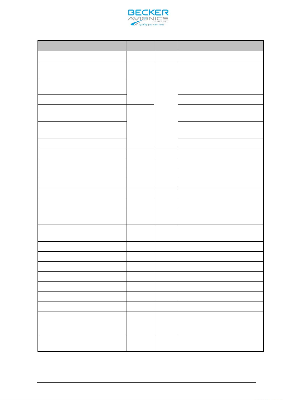
Condition
Section
Cat.
Description
Temperature and Altitude
4.0
Temperature Variation
5.0
Humidity
6.0
Shock and Crash Safety
7.0
Vibration
8.0
Explosion Proofness
9.0
Water Proofness
10.0
Fluids Susceptibility
11.0
Sand and Dust
12.0
Fungus Resistance
13.0
Salt Spray
14.0
Magnetic Effect
15.0
Power Input
16.0
Voltage Spike
17.0
AR6201 - RT6201 - RCU6201 - AR6203
C4
Ground Survival Low
Temperature
Short-Time Operating Low
Temperature
Low Operating Temperature -20 deg C
High Ground Survival
Temperature
High Short-Time Operating
Temp.
High Operating Temp. +55 deg C
In-flight Loss of Cooling 4.5.5 - No forced cooling required
Altitude 4.6.1
Decompression 4.6.2 N/A
Overpressure 4.6.3 N/A
4.5.1
C4
4.5.2
C4
B 5 deg C per minute
A Standard
-55 deg C
-20 deg C
+85 deg C
+70 deg C
35000 ft
B
S+U
- N/A
Y -
- N/A
- N/A
- N/A
- N/A
Z 1 degree deflection at 0.3 m
B
A
Fixed-wing and Helicopter,
standard
Test curve M+G Fixed-wing +
Helicopter
DC installations with
battery of significant
capacity
High degree of protections
against voltage spikes
DV 14307.03 Issue 1 09/2013 Page 1-15
Condition
Section
Cat.
Description
Audio Freq. Conducted
Susceptibility
18.0
Induced Signal Susceptibility
19.0
Radio Frequency
Susceptibility
20.0
Emission of Radio Frequency
Energy
21.0
Equipment where interference
Lightning Induced Transients
Susceptibility
22.0
Lightning Direct Effects
23.0
Icing
24.0
Electrostatic Discharge
25.0
Fire, Flammability
26.0
Condition
Section
Cat.
Description
Temperature and Altitude
4.0
AR6201 - RT6201 - RCU6201 - AR6203
B
DC installations with
battery of significant
capacity
1.9 Environmental Qualification RT6201
AC
RW
B
A1E3X
- N/A
- N/A
A
- N/A
Primary power DC or AC,
400Hz
Interim high intensity
radiated fields
should be controlled to a
tolerable level
Pin test waveform A, level 3
Cable bundle test waveform
E, level 3
Equipment operated in an
aerospace environment
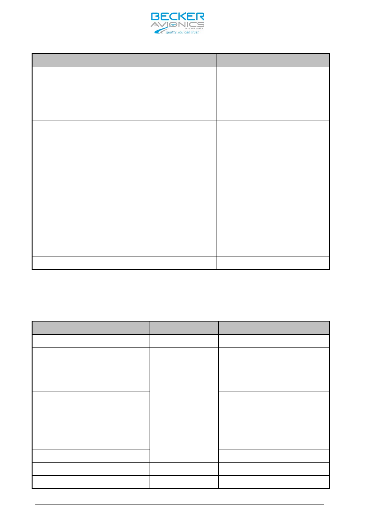
Under environmental test condition in accordance with the pr ocedures set
forth in EUROCAE/RTCA Document ED-14F/DO-160F the following performance
has been demonstrated.
C4
Ground Survival Low
Temperature
Short-Time Operating Low
Temperature
Low Operating Temperature -40 deg C
High Ground Survival
Temperature
High Short-Time Operating
Temp.
High Operating Temp. +55 deg C
In-flight Loss of Cooling 4.5.5 - No forced cooling required
4.5.1
C4
4.5.2
-55 deg C
-40 deg C
+85 deg C
+70 deg C
Altitude 4.6.1 C4 35000 ft
Page 1-16 DV 14307.03 Issue 1 09/2013

Condition
Section
Cat.
Description
Temperature Variation
5.0
Humidity
6.0
Shock and Crash Safety
7.0
Vibration
8.0
Explosion Proofness
9.0
Water Proofness
10.0
Fluids Susceptibility
11.0
Sand and Dust
12.0
Fungus Resistance
13.0
Salt Spray
14.0
Magnetic Effect
15.0
Power Input
16.0
Voltage Spike
17.0
Audio Freq. Conducted
Susceptibility
18.0
Induced Signal Susceptibility
19.0
Radio Frequency
Susceptibility
20.0
Emission of Radio Frequency
Energy
21.0
Lightning Induced Transients
Susceptibility
22.0
Lightning Direct Effects
23.0
AR6201 - RT6201 - RCU6201 - AR6203
Decompression 4.6.2 N/A
Overpressure 4.6.3 N/A
B 5 deg C per minute
A Standard
B
S+U
- N/A
Y N/A
- N/A
- N/A
- N/A
- N/A
Z
B
A
Fixed-wing and Helicopter,
standard
Test curve M+G fixed-wing +
helicopter
1 degree deflection at 0.3
m
DC installations with
battery of significant
capacity
High degree of protections
against voltage spikes
DV 14307.03 Issue 1 09/2013 Page 1-17
DC installations with
B
AC
SW
B
A1E3X
- N/A
battery of significant
capacity
Primary power DC or AC, 400
Hz
Interim High Intensity
Radiated Fields
Equipment where
interference should be
controlled to a tolerable
level
Pin test waveform A, level
3
Cable bundle test waveform
E, level 3

Condition
Section
Cat.
Description
Icing
24.0
Electrostatic Discharge
25.0
Fire, Flammability
26.0
Connector Kit CK4201-S (soldering version)
Article-No. 0879.304-954
Connector Kit CK4201-C (crimp version)
Article-No. 0514.901-954
Connector Kit CK6200-S (soldering version)
Article-No. 0617.903-954
Connector Kit CK6200-C (crimp version)
Article-No. 0617.891-954
AR6201 - RT6201 - RCU6201 - AR6203
- N/A
A
Equipment operated in an
aerospace environment
- N/A
1.10 Accessories Available accessories for 620X can be purchased with the following
Article Numbers. The connector kit or mounting kit as required for
equipment installation is normally included in the delivery of your
purchased Transceiver. The following information is needed for spare
part order.
1 Dsub25-s Article no. 0725.021-277
1 Connector housing Article no. 0775.479-277
1 Antenna plug Article no. 0725.706-277
1 Label “COMM” Article no. 0711.111-258
1 Dsub25-s Article no. 0472.921-277
1 Connector housing Article no. 0775.479-277
1 Antenna plug Article no. 0725.706-277
1 Label “COMM” Article no. 0711.111-258
1 Dsub25-s Article no. 0725.021-277
1 Dsub25-p Article no. 0726.331.277
2 Connector housings Article no. 0775.479-277
1 Antenna plug Article no. 0725.706-277
1 Label “COMM” Article no. 0711.111-258
1 Dsub25-s Article no. 0472.921-277
1 Dsub25-p Article no. 0891.551-277
2 Connector housings Article no. 0775.479-277
1 Antenna plug Article no. 0725.706-277
1 Label “COMM” Article no. 0711.111-258
Page 1-18 DV 14307.03 Issue 1 09/2013
 Loading...