

Page 1
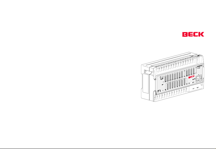
The CPU I/O Modules
FEC FC20, FC21, FC22, FC23 , FC30
and FC34
Powerful AMD processor
AM186 (20 Mhz, 2 Mips) with 16-bit memory access, 256 Kbytes
or 512 Kbytes of RAM
Flash disk
Ethernet 10BASE T (FC34)
Telnet, TFTP, TCP/IP, Web-Server
IPC FEC
®
FEC_ FCXX_ HE12 Version 1.2 as of 03.07.2000
Page 1
A member
of the
Festo
group
Page 2

Contents
Foreword ...................................................................................................................................... 6
Customer service experience ........................................................................ 6
About this manual ......................................................................................... 7
FEC - The Control CPU .................................................................................... 7
CE Confirmation ............................................................................................ 8
Important installation instructions ................................................................ 8
User safety and device protection ................................................................ 10
Warnings ....................................................................................................... 10
Information bar functions ............................................................................. 11
Short description of module variants ............................................................ 12
Installation and use ..................................................................................................................... 15
Area of use .................................................................................................... 15
Scope of delivery ........................................................................................... 15
IPC FEC
®
FEC_ FCXX_ HE12 Version 1.2 as of 03.07.2000
Page 2
Page 3

IPC FEC
FC components 20/21/22/23/30/34 ............................................................ 16
Start-up requirements................................................................................... 21
During installation ......................................................................................... 22
During mounting ........................................................................................... 23
Mounting ....................................................................................................... 24
DC supply, power-consuming inputs .............................................................. 25
DC supply, power-supplying inputs ................................................................ 26
AC power supply, power-consuming inputs ................................................... 27
AC power supply, power supplying inputs ...................................................... 28
The COM Programming Interface .................................................................. 29
Example connection (FEC to external computer) .......................................... 30
Example connection (FEC to external computer) .......................................... 31
COM interface pin assignment ...................................................................... 32
COM interface pin assignment ...................................................................... 33
EXT interface pin assignment ........................................................................ 34
Example crossover cable connection with the external interface ................. 35
Network connector (TP) pin assignment ....................................................... 36
Networking of two FEC FC34 .......................................................................... 37
Network configuration with 10BASE T ........................................................... 38
®
FEC_ FCXX_ HE12 Version 1.2 as of 03.07.2000
Page 3
Page 4

During wiring ................................................................................................. 40
Transistor output wiring diagram .................................................................. 42
Relay output wiring diagram ......................................................................... 43
Solid-state relay outputs wiring diagram ...................................................... 44
Relay output wiring diagram ......................................................................... 45
Service life of relay output contacts .............................................................. 46
Output behaviour if overload/short circuit occurs the FC30/FC34 ................ 47
Important notes ............................................................................................ 48
Adapted PC compatibility .............................................................................. 50
Software requirements ................................................................................. 51
Differences to industry standard PC ............................................................. 52
Additional features compared to industry standard PC ................................ 52
Special functions .......................................................................................................................... 53
RUN/STOP switch .......................................................................................... 53
Status LED ..................................................................................................... 53
Fast counters ................................................................................................. 53
Interrupt inputs ............................................................................................. 53
IPC FEC
®
FEC_ FCXX_ HE12 Version 1.2 as of 03.07.2000
Page 4
Page 5

Incremental encoder ..................................................................................... 54
Analog potentiometer (trimmer) ................................................................... 54
The timer function ......................................................................................... 54
Extension interface/remote expansion ........................................................ 55
Ethernet network .......................................................................................... 57
Fault fixing .................................................................................................................................... 58
Troubleshooting information ........................................................................ 58
What do I do if.. ........................................................................................... 58
Appendix ...................................................................................................................................... 61
Manual change status................................................................................... 61
Hardware change status ............................................................................... 61
Opening the housing..................................................................................... 62
Technical data ............................................................................................... 67
Ordering information ..................................................................................... 74
IPC FEC
®
FEC_ FCXX_ HE12 Version 1.2 as of 03.07.2000
Page 5
Page 6

Foreword
Customer service experience
As far as we are concerned, our companys
reputation as an innovative source of ideas
represents confirmation of our standards and
also an obligation to maintain them. Our reputation is based on communicating with our
customers and carefully monitoring the market.
Our customers make extremely high demands
with regard to reliability, service life, flexibility,
ease of operation and environmental compatibility. They also expect expert advice, rapid
service, qualified support and product training.
IPC FEC
®
FEC_ FCXX_ HE12 Version 1.2 as of 03.07.2000
We have been providing software, hardware,
service and information for industrial PCs and
automation equipment for 15 years. Reliable
delivery and service are combined with a continuously expanding product range and everdecreasing intervals between new innovations.
Our target is customer satisfaction. Our customers success, and therefore our own, is based
on consistent quality management, a unique
range of products and highly motivated staff
who are full of ideas.
Page 6
Page 7

About this manual
We would like to thank you for choosing to buy
the FEC FC34-FST module. We are pleased to
welcome you as one of our customers.
Please read through this manual carefully be
before beginning with the installation. The FEC
FEC FC20, FEC FC21, FEC FC22, FEC FC23, FEC
FC30 and FC34 module is designed to be a lowcost, versatile industrial controller that is quick
and easy to install and can be operated by
personnel with limited experience of programmable controllers.
This manual contains text, diagrams and explanations that show the reader how the module is correctly installed and safety used and
operated. Before installing the module the
contents of this manual must have been read
and understood. If in doubt about the operation or use of the module, please contact your
nearest BECK IPC GmbH office.
FEC - The Control CPU
Pure control technology, 12 inputs, 8 outputs
with status LED, network, ( FC34 only )with fast
counter inputs, with connection facility for a
FEC as an I/O module. All of this fits into a FEC!
IPC FEC
®
FEC_ FCXX_ HE12 Version 1.2 as of 03.07.2000
Page 7
Page 8

CE Confirmation
The manufacturer BECK IPC GmbH declares in
sole responsibility that the products
FEC FC20, FEC FC21, FEC FC22, FEC FC23,
FEC FC30 and FEC FC34
complies with directive 89/336/EWG in harmonisation with the following standards:
Noise immunity EN 50082-2
Emitted interference EN 50081-2
This is a class A device. It can cause transmission interference in built-up areas. In this case it
is the responsibility of the user to take appropriate measures and bear any costs incurred
by problems of this nature.
Important installation instructions
Isolating conditions:
Only use power supplies that guarantee reliable operating voltage isolation in accordance
with IEC 742 / EN 60742 / VDE 0551, PELV with
at least 4 kV of dielectric strength for the 24 V
DC power supply (power connections) and the
power supply to the digital inputs (nominal 24
V DC).
IPC FEC
®
FEC_ FCXX_ HE12 Version 1.2 as of 03.07.2000
Page 8
Page 9

Switched mode power supplies with reliable
isolation as per EN 60950 / VDE 0805 are
permitted.
The PS1 PSE3 power supply meet the above
requirements. The 24 V DC sensor supply provided in the FC21 and FC23 products meets the
above requirement for reliable mains voltage
isolation and can therefore be used for supplying the digital inputs, provided that potential
isolation from the internal system voltage is
not required for providing interference immunity, for example.
Power supplies with basic isolation and 2.5 kV
of dielectric strength are permitted for supplying the power to the digital transistor outputs (24 V DC nominal).
The power relays that are used allow mains
voltages of overload category II to be switched
directly, and the isolation strength between
the contacts and the coil is greater than 4 kV.
The solid-state relays that are used allow AC
voltages in overload category I to be switched.
Interference immunity:
Only shielded cable should be used for TP and
cross-over cables. TP cables of type S/STP are
suitable. The shields should be connected to
an interference-free earth at both ends, over a
large area and with low impedance.
IPC FEC
®
FEC_ FCXX_ HE12 Version 1.2 as of 03.07.2000
Page 9
Page 10

The housings of the hubs that are used should
also be earthed with low impedance.
User safety and device protection
This manual is intended for the use of trained
specialists when installing the FEC FC34-FST
module. Safety guidelines are defined in the
European directives for machinery, low voltage and EMC. Throughout this manual, symbols
are used to highlight information relating to
the users personal safety and the safeguarding of the machines integrity. Whenever any
of these symbols are encountered, the associated note should be read and understood.
Warnings
The identified danger could
possibly cause damage to persons or property.
Point of further interest or more
detailed explanation.
!
STOP
IPC FEC
®
FEC_ FCXX_ HE12 Version 1.2 as of 03.07.2000
Page 10
Page 11

Information bar functions
Since this manual describes several types of
FEC modules, the right-hand margin contains
an information bar informing you whether the
page contains important information for your
particular FEC module.
These pages do not apply to your FEC.
These pages contain important information which you must read.
FC20
FC21
FC22
FC23
FC30
FC34
IPC FEC
®
FEC_ FCXX_ HE12 Version 1.2 as of 03.07.2000
Page 11
Page 12
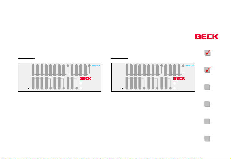
Short description of module variants
FEC FC20
24V 0V
01 0213243567
Sensor
24V 0V
Supply
OUT
Power
40123 201 3
756
120
120 33C044 55C166 77C2
S0IN
FC20
FEC FC21
24V 0V
01 0213243567
FC20
S1
Power
Run
Sensor
Supply
OUT
120
Power
120 33C044 55C166 77C2
LN
40123 201 3
756
S0IN
Power
Run
S1
FC21
FC21
FC22
12 inputs and 8 relay outputs, supply voltage
24 V DC
Dimensions: 130 x 80 x 35 mm
IPC FEC
®
FEC_ FCXX_ HE12 Version 1.2 as of 03.07.2000
12 inputs and 8 relay outputs, supply voltage
110 to 230 V AC
Dimensions: 130 x 80 x 60 mm
Page 12
FC23
FC30
FC34
Page 13
FEC FC22 FEC FC23
24V 0V
01 0213243567
Sensor
Supply
OUT
Power
24V 0V
40123 201 3
756
120
120 33C044 55C166 77C2
S0IN
FC22
S1
Power
Run
Power
LN
24V 0V
Sensor
Supply
OUT
01 0213243567
40123 201 3
120
120 33C044 55C166 77C2
756
FC20
FC21
FC23
S0IN
S1
Power
Run
FC22
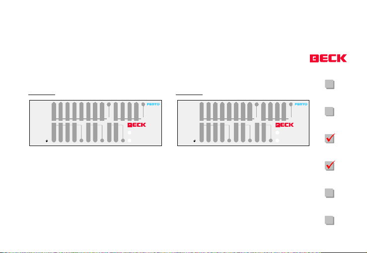
12 inputs and 8 solid-state relay outputs, supply voltage 24 V DC
Dimensions: 130 x 80 x 35 mm
IPC FEC
®
FEC_ FCXX_ HE12 Version 1.2 as of 03.07.2000
12 inputs and 8 solid-state relay outputs, supply voltage 110 to 230 V AC
Dimensions: 130 x 80 x 60 mm
Page 13
FC23
FC30
FC34
Page 14
FEC FC30 FEC FC34
24V 0V
01 0213243567
Sensor
Supply
OUT
Power
24V 0V
C0
40123 201 3
012
344556677
3
2
01
FC30
75C+6
S0IN
S1
Power
C-
Run
24V 0V
24V 0V
Sensor
Supply
OUT
Power
01 0213243567
40123 201 3
012
344556677
3
2
01
C0
FC20
FC21
FC34
75C+6
S0IN
S1
TP
Power
C-
Run
FC22
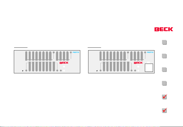
12 inputs and 8 outputs, consisting of 2 relay
and 6 transistor outputs, supply voltage 24 V
DC
Dimensions: 130 x 80 x 35 mm
IPC FEC
®
FEC_ FCXX_ HE12 Version 1.2 as of 03.07.2000
12 inputs and 8 outputs, consisting of 2 relay
and 6 transistor outputs, Ethernet 10Base T,
supply voltage 24 V DC
Dimensions: 130 x 80 x 35 mm
Page 14
FC23
FC30
FC34
Page 15

Installation and use
FC20
Area of use
The modules described in this manual are FEC
components that have been designed for process control.
IPC FEC
®
FEC_ FCXX_ HE12 Version 1.2 as of 03.07.2000
Scope of delivery
The scope of delivery of the module includes:
one module FEC FC20, FEC FC21, FEC FC22,
FEC FC23, FEC FC30 or FEC FC34
Up-to-date information such as drivers, manuals or datasheets can be obtained from our
Website at:
http://www.beck-ipc.com
under the point download.
Page 15
FC21
FC22
FC23
FC30
FC34
Page 16
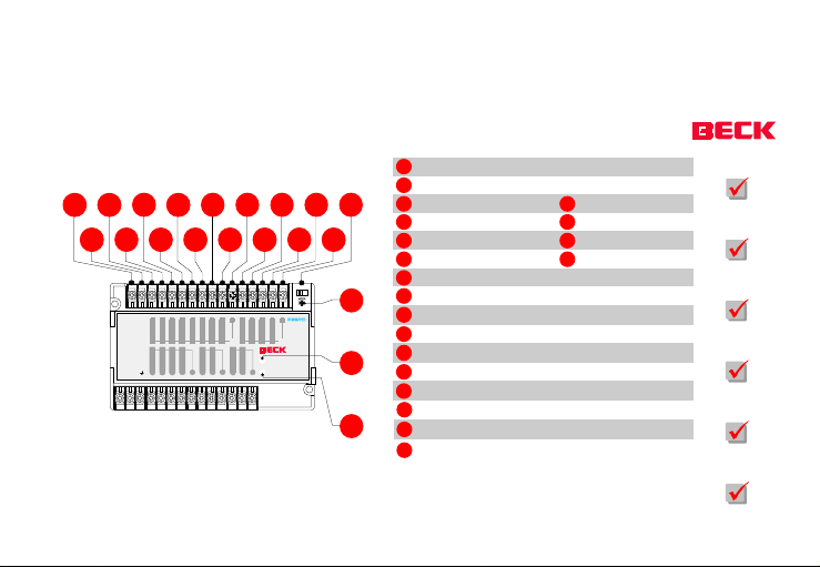
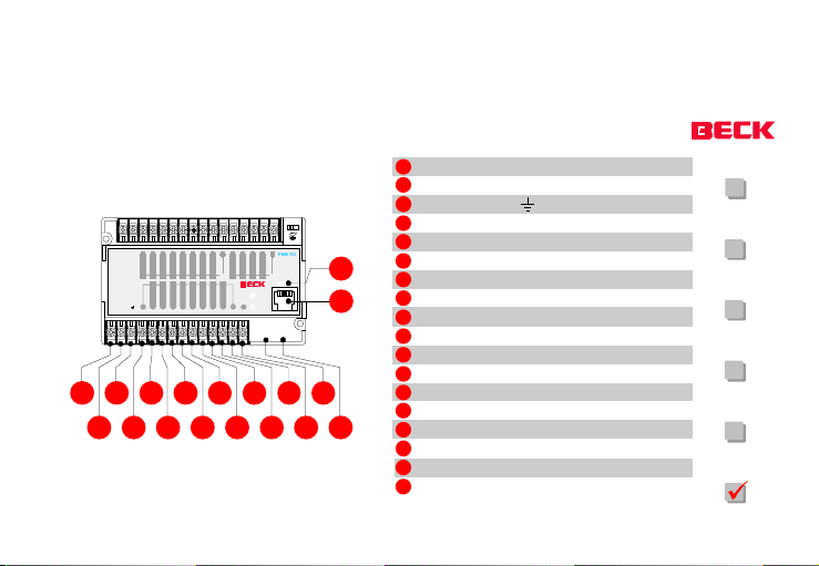
The elements of the FC 20/21/22/23/30/34
pply
1234567891011121314151617
RUN STOP
24V 0V
01 0213243567
Sensor
Su
OUT
Power
24V 0V
40123 201 3
756
120
120 3!C044 5#C166 77C2
Power
Run
EXT. COM
FC20
S1S0IN
1
Sensor supply 24 V DC 100 mA
2
Sensor supply 0 V
3
Input E0.0
4
Input E0.1
5
Input E0.2
6
Input E0.3
11
Shared potential S0 for E0.0 ... E0.7
12
18
19
20
Input E1.0
13
Input E1.1
14
Input E1.2
15
Input E1.3
16
Shared potential S1 for E1.0 ... E1.7
17
RUN/STOP s witch
18
Analog potentiometer (trimmer)
19
Power LE D (power supply)
20
Status LED (status indicator)
7
8
9
10
Input E0.4
Input E0.5
Input E0.6
Input E0.7
FC20
FC21
FC22
FC23
FC30
FC34
®
IPC FEC
FEC_ FCXX_ HE12 Version 1.2 as of 03.07.2000
Page 16
Page 17
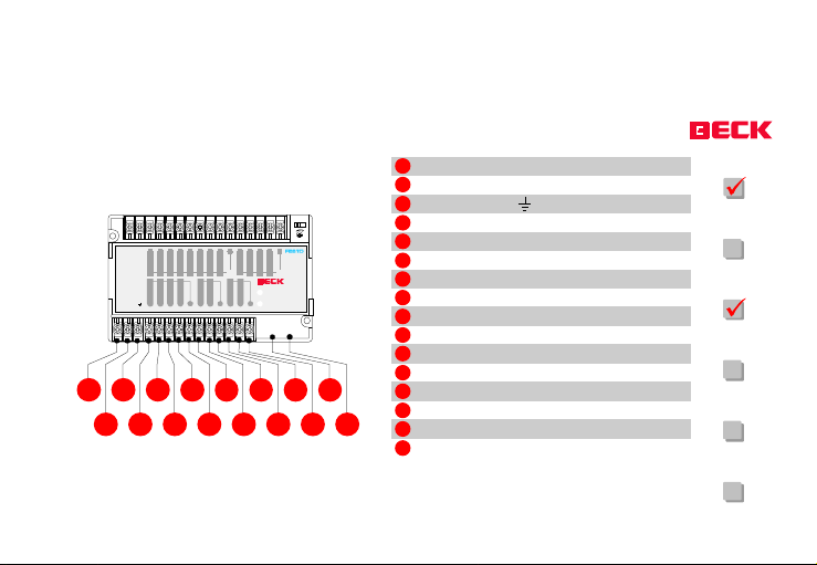
RUN STOP
pply
24V 0V
01 0213243567
Sensor
Su
OUT
Power
24V 0V
40123 201 3
756
120
120 33C044 55C166 77C2
Power
Run
EXT. COM
FC20
S1S0IN
212223242526272829303132333435
21
Sensor supply 24 V DC
22
Sensor supply 0 V
23
Function earth
24
Output A0.0
25
Output A0.1
26
Output A0.2
27
Output A0.3
28
Shared connection C0 for A0.0...A0.3
29
Output A0.4
30
Output A0.5
31
Shared connection C1 for A0.4...A0.5
32
Output A0.6
33
Output A0.7
34
36
Shared connection C2 for A0.6 ...A0.7
35
Connecto r for expansions (EX T)
36
Serial inte rface(COM)
FC20
FC21
FC22
FC23
FC30
FC34
®
IPC FEC
FEC_ FCXX_ HE12 Version 1.2 as of 03.07.2000
Page 17
Page 18
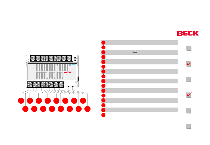
RUN STOP
pply
24V 0V
01 0213243567
Sensor
Su
OUT
Power
LN
40123 201 3
756
120
120 33C044 55C166 77C2
Power
Run
EXT. COM
FC21
S1S0IN
212223242526272829303132333435
21
Voltage supply L
22
Voltage supply N
23
Function earth
24
Output A0.0
25
Output A0.1
26
Output A0.2
27
Output A0.3
28
Shared connection C0
29
Output A0.4
30
Output A0.5
31
Shared connection C1
32
Output A0.6
33
Output A0.7
34
36
Shared connection C2
35
Connecto r for expansio ns (EXT )
36
Serial i nterface (COM)
FC20
FC21
FC22
FC23
FC30
FC34
®
IPC FEC
FEC_ FCXX_ HE12 Version 1.2 as of 03.07.2000
Page 18
Page 19
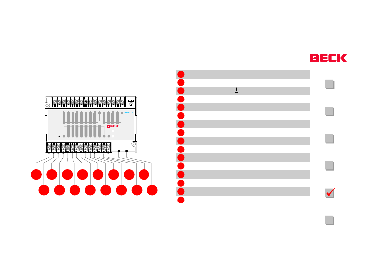
RUN STOP
pply
24V 0V
01 0213243567
Sensor
Su
40123 201 3
012
75C+6
3344556677C-
OUT
Power
24V 0V
C0 0 1 2
Power
Run
S1S0IN
EXT. COM
FC30
212223242526272829303132333435
21
Sensor supply 24 V DC
22
Sensor supply 0 V
23
Function earth
24
Shared connection C0 for A0.0 ... A0.1
25
Output A0.0
26
Output A0.1
27
Output A0.2
28
Output A0.3
29
Output A0.4
30
Output A0.5
31
Output A0.6
32
Output A0.7
33
Output supply C+
34
36
Output supply C-
35
Connecto r for expansions (EX T)
36
Serial inte rface (COM)
FC20
FC21
FC22
FC23
FC30
FC34
®
IPC FEC
FEC_ FCXX_ HE12 Version 1.2 as of 03.07.2000
Page 19
Page 20
RUN STOP
pply
y
01 0213243567
24V 0V
Sensor
Su
40123 201 3
012
344556677
3
75C+6
OUT
Power
24V 0V
C0 0 1 2
FC34
S0IN
S1
TP
Power
Run
C-
EXT. COM
212223242526272829303132333435
21
Sensor supply 24 V DC
22
Sensor supply 0 V
Function earth
23
24
Shared connection C0 for A0.0 ... A0. 1
25
Output A0.0
26
38
37
36
Output A0.1
27
Output A0.2
28
Output A0.3
29
Output A0.4
30
Output A0.5
31
Output A0.6
32
Output A0.7
33
Output supply C+
34
Output supply C-
35
Connecto r for expansio ns (EXT )
36
Serial i nterface (COM)
37
Network connection 10Base T
38
Link/Tra ffic LED for n etwork activit
FC20
FC21
FC22
FC23
FC30
FC34
®
IPC FEC
FEC_ FCXX_ HE12 Version 1.2 as of 03.07.2000
Page 20
Page 21

Start-up requirements
One FEC FC20/FC21/FC22/FC23, FEC FC30
or FEC FC34 module (scope of delivery)
Sensor supply 24 V DC, e. g. PS1 PSE3
When using the FEC FC30 and FEC FC34
modules, an SM14 connecting cable between the FEC and the external computer,
consisting of a null model cable and an
adapter cable.
When using one of the FEC FC20/FC21/
FC22/FC23 modules, connecting cables FEC
KSD2 and PS1 ZK11 between the abovementioned FEC modules and the external
computer.
External computer such as PC, laptop etc.
with a free COM port (preferably a Windows system).
Module-specific software with drivers and
example programs. This software can be
downloaded from the Internet address
http://www.beck-ipc.com
The software is also available on CD.
FC20
FC21
FC22
FC23
FC30
FC34
IPC FEC
®
FEC_ FCXX_ HE12 Version 1.2 as of 03.07.2000
Page 21
Page 22

During installation
When you are installing the FEC, please pay
attention to the ambient conditions in which
the device will normally be operating.
Please do not install the FEC
in areas that are subjected to
excessive amounts of dust, oil
spray, conductive dust or corrosive gas;
in areas that are subjected to shock or
vibration;
in areas that are subjected to high tempe-
ratures, direct sunlight, moisture or rain;
!
near high voltage devices or cables.
FC20
FC21
FC22
FC23
FC30
FC34
IPC FEC
®
FEC_ FCXX_ HE12 Version 1.2 as of 03.07.2000
Page 22
Page 23

During mounting
Always install the device as far away as possible from high voltage devices and large power
supplies.
Please ensure that no pieces of wire,
fillings or swarf fall into the device
when you are drilling holes or connecting wires.
Do not install the device immediately above a
heat-generating source, such as a heater, current converter or high wattage resistor.
If the ambient temperature in the switch cabinet is above 55ºC, a ventilator must be installed in order to provide external ventilation.
!
FC20
FC21
FC22
FC23
FC30
FC34
IPC FEC
®
FEC_ FCXX_ HE12 Version 1.2 as of 03.07.2000
Page 23
Page 24

Mounting
The module can be screw-connected using the
mounting holes (4 mm) at either side or directly
connected to a top-hat rail by hooking the
module onto the upper edge of the rail and
pulling the mounting bracket down by hand or
using a suitable tool. The module now automatically latches onto the top-hat rail.
FC20
FC21
FC22
FC23
FC30
FC34
IPC FEC
®
FEC_ FCXX_ HE12 Version 1.2 as of 03.07.2000
Page 24
Page 25
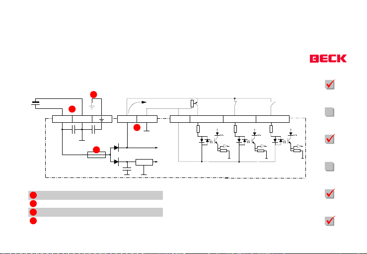
DC supply, power-consuming inputs
y
y
(Sensor supply utilisation)
A
B
24 V
0 V 24 V 0 V S0
D
FEC
A
Function earth
B
Direct current suppl
C
Sensor suppl
D
Fuse 315 mA slow (T315m A)
IPC FEC
®
FEC_ FCXX_ HE12 Version 1.2 as of 03.07.2000
FC20
C
24 V
V
DC/DC
CC
(5V)
E0.0 E0.1 E0.2
V
CC
V
CC
FC21
V
CC
FC22
FC23
FC30
FC34
Page 25
Page 26
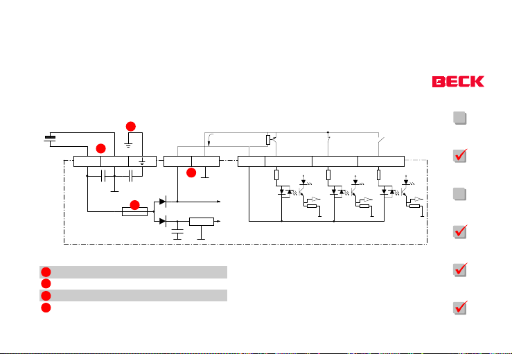
DC supply, power-supplying inputs
y
y
(Sensor supply utilisation)
A
B
24 V
0 V 24 V 0 V
D
FEC
A
Function earth
B
Direct current suppl
C
Sensor suppl
D
Fuse 3 15 mA slow (T3 15mA)
IPC FEC
®
FEC_ FCXX_ HE12 Version 1.2 as of 03.07.2000
FC20
S0
C
E0.0
DC/DC
24 V
V
(5V)
CC
E0.1
V
CC
E0.2
V
CC
FC21
V
CC
FC22
FC23
FC30
FC34
Page 26
Page 27
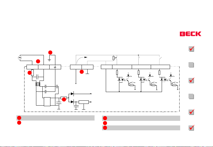
AC power supply, power-consuming inputs
y
y
(Sensor supply utilisation)
A
B
L N 24 V 0 V S0
D
E
A
Function earth
B
AC power suppl
®
IPC FEC
DC/DC
FEC
C
DC/DC
FEC_ FCXX_ HE12 Version 1.2 as of 03.07.2000
24 V
V
CC
(5V)
C
Sensor suppl
D
Fuse 315 mA slow (T315 mA)
E
Fuse 800 mA slow (T800 mA)
E0.0
FC20
FC21
E0.1
V
CC
E0.2
V
CC
V
CC
FC22
FC23
FC30
FC34
Page 27
Page 28
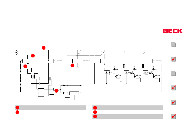
AC power supply, power supplying inputs
y
p
y
(Sensor supply utilisation)
A
B
L N
D
E
FEC_ FCXX_ HE12 Version 1.2 as of 03.07.2000
A
Function earth
B
AC
IPC FEC
DC/DC
FEC
ower suppl
®
24 V
0 V S0
C
24 V
V
DC/DC
(5V)
E0.0
CC
C
Sensor suppl
D
Fuse 315 mA slow (T31 5 mA)
E
Fuse 800 mA slow (T80 0 mA)
FC20
FC21
E0.1
V
CC
E0.2
V
CC
V
CC
FC22
FC23
FC30
FC34
Page 28
Page 29

The COM Programming Interface
For FEC FC20, FEC FC21, FEC FC22, and FEC
FC23:
Connect the FEC module to the development
computer using the (FEC KSD2) connecting
cable. To do this, plug the end of the FEC KSD2
with the RJ11 plug attached to it into the socket
marked COM. Connect the other end to an
interface on your development computer.
For FEC FC30 and FEC FC34:
Connect the FEC module to the development
computer using the SM14 connecting cable.
FC20
FC21
FC22
FC23
FC30
FC34
IPC FEC
®
FEC_ FCXX_ HE12 Version 1.2 as of 03.07.2000
Page 29
Page 30
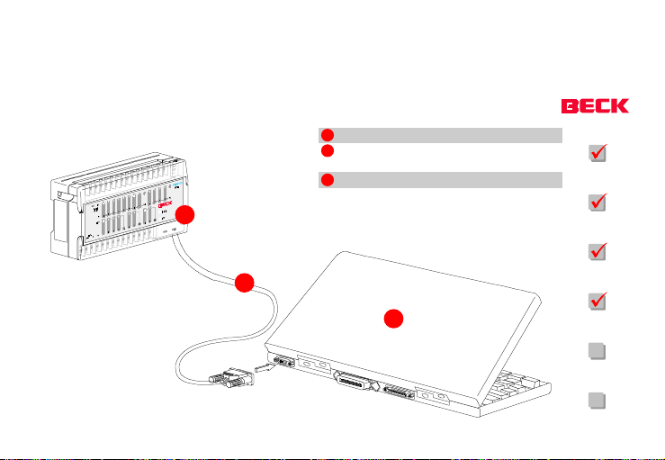
Example connection (FEC to external computer)
1
1
FEC
2
KSD2 connec ting cable for FC20 /FC21/
FC22/FC23
3
External PC (Laptop)
FC20
FC21
FC22
IPC FEC
2
3
FC23
FC30
FC34
®
FEC_ FCXX_ HE12 Version 1.2 as of 03.07.2000
Page 30
Page 31
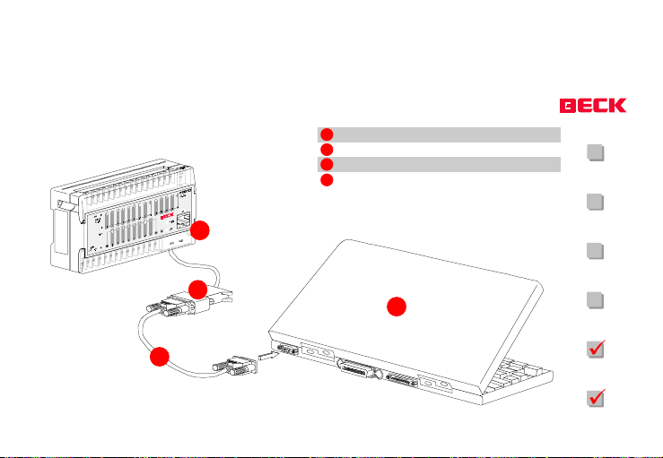
Example connection (FEC to external computer)
1
FEC
2
SM14 connecting cable for FC30/FC34
3
Externnal PC (Laptop)
4
Null modem cabl e
FC20
FC21
IPC FEC
1
2
3
FC22
FC23
FC30
4
FC34
®
FEC_ FCXX_ HE12 Version 1.2 as of 03.07.2000
Page 31
Page 32
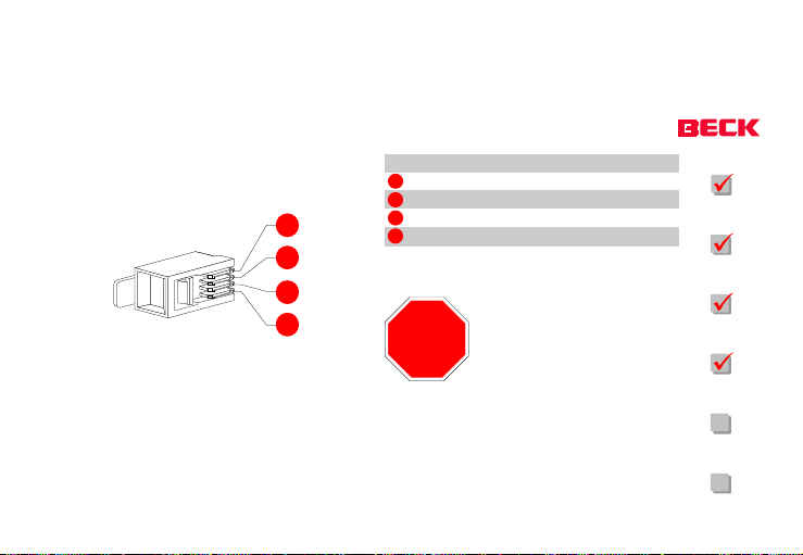
COM interface pin assignment
Pin no.
1
2
1
2
3
4
3
4
STOP
Signalname
RXD
TXD
DTR
GND
The opto-decoupled FEC-COM
interface works at signal levels
within the +/- 5 V to +/- 15 V
range. If communication pro-
FC20
FC21
FC22
FC23
blems occur, the service device
that you are using may be supplying a lesser level.
FC30
FC34
IPC FEC
®
FEC_ FCXX_ HE12 Version 1.2 as of 03.07.2000
Page 32
Page 33
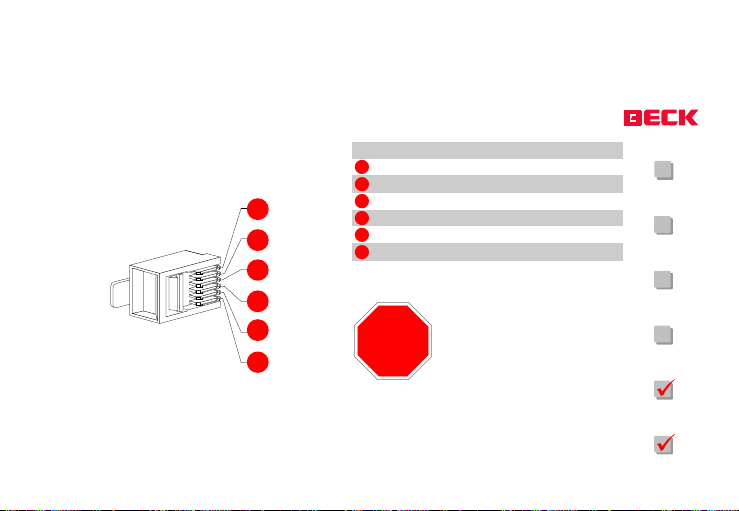
COM interface pin assignment
Pin no.
1
2
1
2
3
4
5
6
3
4
5
6
STOP
Signal name
+5 V
GND
TXD
RXD
CTS
RTS
The FEC COM interface works
at TTL levels (5 V). Only use the
provided accessories, e.g. SM
14.
FC20
FC21
FC22
FC23
FC30
FC34
IPC FEC
®
FEC_ FCXX_ HE12 Version 1.2 as of 03.07.2000
Page 33
Page 34
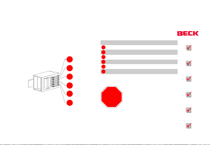
EXT interface pin assignment
Pin no.
1
2
1
2
3
4
5
6
3
4
5
6
STOP
Signal name
+5 V
GND
TXD
RXD
CTS
RTS
The FEC-EXT interface works
using TTL levels (5V). Only use
the relevant accessory, e.g.
SM 14.
FC20
FC21
FC22
FC23
FC30
FC34
IPC FEC
®
FEC_ FCXX_ HE12 Version 1.2 as of 03.07.2000
Page 34
Page 35
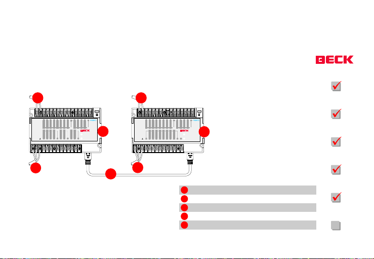
Example crossover cable connection with the external interface
1
24V 0V
01 0213243567
Sensor
Supply
0123 201 3
IN
OUT
120
Power
N
120 3
L
2
®
IPC FEC
RUN STOP
FC21
756
S0
4
3C04
S1
5C16
7
4
Power
4 5
6 7
C2
Run
EXT. COM
1
24V 0V
Sensor
Supply
0123 201 3
IN
OUT
Power
0V
C0 0 1 2
24V
2
3
FEC_ FCXX_ HE12 Version 1.2 as of 03.07.2000
10213243567
4
012
3344556677C-
RUN STOP
FC30
75C+6
S0
S1
5
Power
Run
EXT. COM
1
Local s ensor supply +24 V DC
2
Local voltage supply +24 V DC
3
Crossover cable FEC KSD4
4
FEC FC30 as (master)
5
FEC F C20 as slave ( remote)
The FEC FC20 or FEC FC30 inputs
and outputs can be added to
those of the FEC FC34 using a
FEC KSD4 crossover cable.
Page 35
FC20
FC21
FC22
FC23
FC30
FC34
Page 36
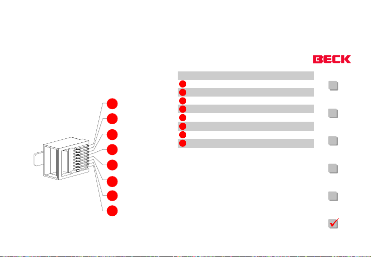
Network connector (TP) pin assignment
1
2
3
4
5
6
7
8
Pin no. Signal name
1
2
3
4
5
6
7
8
TD+
TDRD+
-
-
RD
-
-
FC20
FC21
FC22
FC23
FC30
FC34
IPC FEC
®
FEC_ FCXX_ HE12 Version 1.2 as of 03.07.2000
Page 36
Page 37
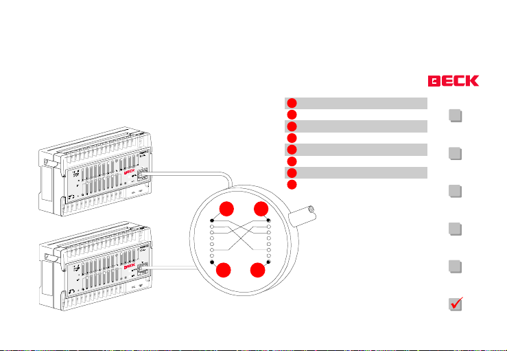
Networking of two FEC FC34
1
TD+
2
TD-
3
RD+
4
not used
5
not used
6
RD-
7
not used
8
not used
FC20
FC21
FC22
IPC FEC
1 1
FC23
FC30
8 8
FC34
®
FEC_ FCXX_ HE12 Version 1.2 as of 03.07.2000
Page 37
Page 38
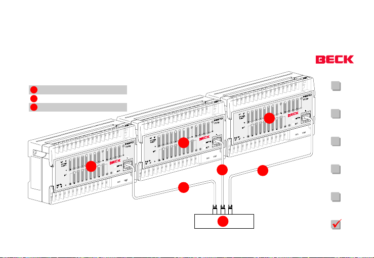
Network configuration with 10BASE T
9
FEC FC34
10
Hub (sta r distributor)
11
Twisted pair cable
9
FC20
FC21
9
FC22
9
FC23
11
11
11
FC30
IPC FEC
10
®
FEC_ FCXX_ HE12 Version 1.2 as of 03.07.2000
Page 38
FC34
Page 39

Segment lengths
y
Max. segment length:
Max. number of transceivers per segment:
Min. distance between transceivers:
100 m
hub-dependent
an
FC20
FC21
FC22
FC23
FC30
FC34
®
IPC FEC
FEC_ FCXX_ HE12 Version 1.2 as of 03.07.2000
Page 39
Page 40

During wiring
Install the input and output signal wires in
separate cable conduits and avoid bunching
them together.
Do not use the same multi-core cable for wiring
the signal inputs and outputs.
FC20
FC21
FC22
FC23
FC30
FC34
IPC FEC
®
FEC_ FCXX_ HE12 Version 1.2 as of 03.07.2000
Page 40
Page 41

y
Warning
If the power s upply terminals are wrongl
connec ted, a s hort ci rcuit betw een
the incomin g direct current wire s
and the power supply cabl e or a
short circuit within the outgoing wires can
caus e consid erable d amage to the modu le.
STOP
Before switching on the power, check the power supply and earth connections and the incoming and outgoing connections.
Please ensure that none of the installation
screws are loose. Make sure that no screw
terminals for external connections are loose.
There must be no visible damage to external
connections.
IPC FEC
®
FEC_ FCXX_ HE12 Version 1.2 as of 03.07.2000
Caution:
Please ensure that the power is switched off
before you replace cables or carry out other
work.
If you need to measure the maximum insulation voltage and the insulating resistance of the
FEC module, disconnect the incoming and outgoing wires and the power cable from the module and carry out the measurements across
all the terminals and the earth terminal using a
common point.
Page 41
FC20
FC21
FC22
FC23
FC30
FC34
Page 42
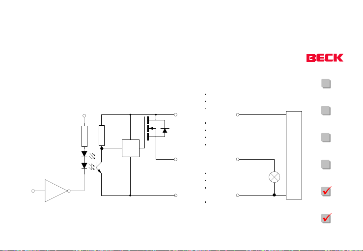
Transistor output wiring diagram
y
FC20
+5 V
1)
KS
1)
Analog current restriction to 4 A / 200 ms
Analog short circuit/overload protection, thermal onl
IPC FEC
®
FEC_ FCXX_ HE12 Version 1.2 as of 03.07.2000
internal external
C+
Output
A0.2 ... A0.7
C-
+24 V
FC21
FC22
FC23
Power supply
Lamp
motor ...
0 V
FC30
FC34
Page 42
Page 43
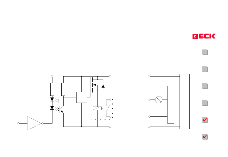
Relay output wiring diagram
FC20
+5 V
*) max. 5 A 250 V AC/ 30 V DC
®
IPC FEC
internal external
C+
KS
*
FEC_ FCXX_ HE12 Version 1.2 as of 03.07.2000
Output
A0.0 ... A0.1
C0
C-
+24 V nom.
0 V
Load su pply
Page 43
FC21
FC22
FC23
Power supply
FC30
FC34
Page 44
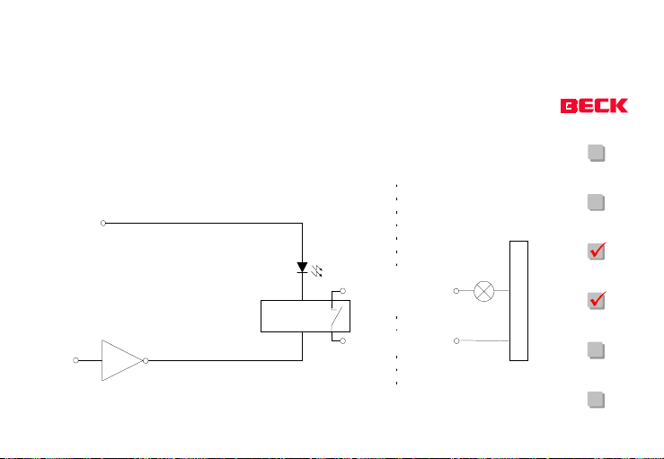
Solid-state relay outputs wiring diagram
FC20
*) max. 264 V AC / 125 V DC
®
IPC FEC
+24 V (interna l)
Solid State
Relais
FEC_ FCXX_ HE12 Version 1.2 as of 03.07.2000
internal external
Output
A0.0 ... A0.3
*
C0
+
-
Load supply
Page 44
FC21
FC22
FC23
FC30
FC34
Page 45
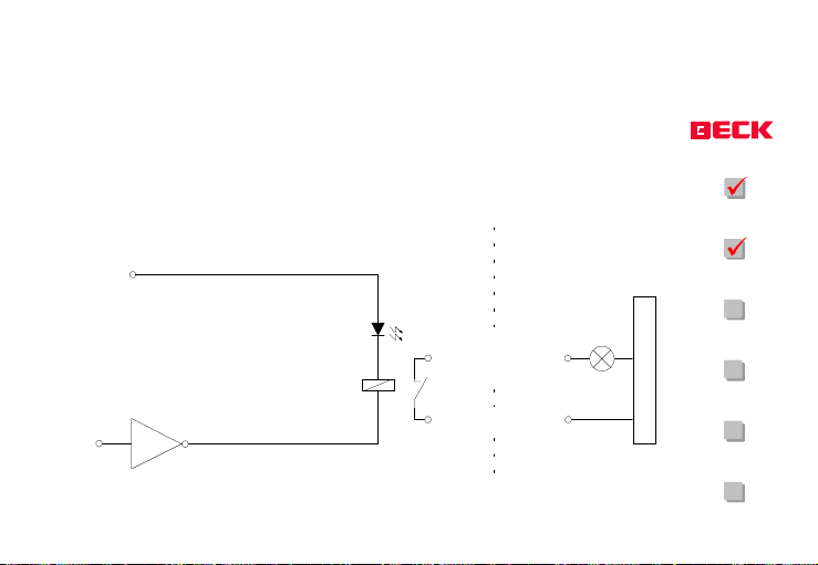
Relay output wiring diagram
FC20
*) ma x. 5A / 2 50 V AC / 30 V DC
®
IPC FEC
+24 V (interna l)
FEC_ FCXX_ HE12 Version 1.2 as of 03.07.2000
internal external
Output
A0.0 ... A0.3
*
C0
+
-
Page 45
FC21
FC22
FC23
Load supply
FC30
FC34
Page 46

Service life of relay output contacts
FC20
Current/load Inductive loadOhmic load
No current
0,2 A
1 A
2 A
5 A max. 100.000 cycles -
20.000.00 0 cycles 20.000.00 0 cycles
1.000.000 cycles 800.000 cycles
500.000 cycles 300.000 cycles
300.000 cycles 100.000 cycles
Measures to suppress voltage surges should
be taken if necessary when using inductive
loads.
IPC FEC
®
FEC_ FCXX_ HE12 Version 1.2 as of 03.07.2000
FC21
FC22
FC23
FC30
FC34
Page 46
Page 47

Output behaviour if overload/short circuit occurs the FC30/FC34
Transistor outputs A0.2 to A0.7 are independently protected against short circuits and
overloads.
If short circuit or overload current is applied,
the switching transistor heats up. The overheating fuse switches the output concerned
off, meaning that the switching transistor can
cool down again. Subsequently the output concerned is reactivated. If overload current is still
present after reactivation, the process starts
again from the beginning.
The process cycle time depends on the magnitude of the load. If there is only a minimal
overload, the cycle time can be up to several
minutes, and if there is a major overload this
time may be less than 1 second.
FC20
FC21
FC22
FC23
FC30
FC34
IPC FEC
®
FEC_ FCXX_ HE12 Version 1.2 as of 03.07.2000
Page 47
Page 48

Important notes
The maximum signal voltage at
the digital inputs may not exceed
the supply voltage
Do not connect any of the unu-
sed terminals.
If loads such as forward/back-
ward motor contactors are present that may be dangerous if
they are switched on simultaneously, external locking mechanisms and programmable locks
should be provided in order to
prevent such loads from being
activated simultaneously.
For EMERGENCY STOP functions
the output loads should be switched off using a switch outside
!
the module that disconnects the
current from the output terminals.
If you connect an EMERGENCY
STOP circuit, please be sure to
comply with local wiring and safety regulations.
Connecting a power surge sup-
pressor parallel to an inductive
load reduces the generation of
electrical interference.
STOP
!
FC20
FC21
FC22
FC23
FC30
FC34
IPC FEC
®
FEC_ FCXX_ HE12 Version 1.2 as of 03.07.2000
Page 48
Page 49

The supply voltage is not protec-
ted against reverse polarity.
Check the polarity of the supply
voltage before starting up.
FC20
!
FC21
FC22
FC23
FC30
FC34
IPC FEC
®
FEC_ FCXX_ HE12 Version 1.2 as of 03.07.2000
Page 49
Page 50

Adapted PC compatibility
y
Component If yesPC compa tible
x86 cor e
8250 UART
-FIFO
8254 PIT
8259 PIC
CMOS RAM
6845 CRT C
8042 KEY B
8272 FDC
IDE n/a
Power on LED
ü
-
n/a
-
-
n/a
n/a
n/a
FC34
ü
ü
IPC FEC
®
FEC_ FCXX_ HE12 Version 1.2 as of 03.07.2000
FC20
The AM186ES/ED chip set that is used in the
FEC is only PC compatible to a limited extent.
80186
ü
NE2000MAC
Status LED
DL MiniBIOSBIOS
If no Workaround (SW)
AMD-specific
AMD-specific
AMD-specific
XT
Fossil drive r
Serial port DMA
PS1 servi ce interrupt
PDS1 service interrupt
Flash memor
Remote consol e
Remote consol e
Flash disk
Packet driver
PS1 servi ce interrupt
Page 50
FC21
FC22
FC23
FC30
FC34
Page 51

Software requirements
BIOS: Datalight MiniBIOS
DOS: Datalight ROM-DOS 5.0 (equivalent
to MS-DOS 5.0); no INT 2Fh support
Function TaskSub funct.
10h 0Eh
11h
12h
14h
16h 0
16h 1
16h 2
19h
1Ah 0
1Ah 1
1Ch
TTY c har output
Get equipment
Get memory size
Serial I/0
(Fossil dr iver)
Ready TTY char
Get TTY status
Get TTY fl ags
Reboot system
Get tick count
Set tick count
Timer tic k (DOS =
55 ms) FST = 13ms)
IPC FEC
®
FEC_ FCXX_ HE12 Version 1.2 as of 03.07.2000
Page 51
Page 52

Differences to industry standard PC
Datalight MiniBIOS with reduced BIOS sup-
port (see previous page for list of BIOS
functions)
Datalight ROM DOS (equivalent to MS-DOS
5.0)
No keyboard and video controller/video
RAM available
Standard I/O diverted to a terminal using
serial interface (DOS INT 21 and BIOS INT
10)
approx. 480 kBytes of free RAM in the FC30/
FC34 and approx. 210 kBytes in the FC20,
FC21, FC22 and FC23.
IPC FEC
®
FEC_ FCXX_ HE12 Version 1.2 as of 03.07.2000
On-board flash disk
Programming of On-chip peripherals
(PIC, timer, UART) completely different from
standard PC
Different IRQ number assignments
Additional features compared to industry standard PC
Service interrupt support of FC34 functions
(digital I/O, counters, Ethernet network,
status LED).
Page 52
FC20
FC21
FC22
FC23
FC30
FC34
Page 53

Special functions
FC20
RUN/STOP switch
The FEC has a RUN/STOP switch that can be
interrogated by the software.
Status LED
The FEC has a status LED which can be green,
orange or red. The LED can be programmed by
the software that is being used and usually
indicates the current program status. The LED
can also flash in all three colours.
IPC FEC
®
FEC_ FCXX_ HE12 Version 1.2 as of 03.07.2000
Fast counters
Inputs E1.2 and E1.3 can be independently
configured as fast counter inputs and used to
count counter pulses up to a frequency of 2
kHz. The counters are 16-bit (0 to 65535) and
are configured and evaluated using the provided program library. Inputs that are configured as counters can also be read in as normal
digital inputs.
Interrupt inputs
Inputs E1.0 and E1.1 can be individually configured as interrupt inputs. Like the counter inputs, the interrupt inputs can be software con-
Page 53
FC21
FC22
FC23
FC30
FC34
Page 54

figured and high level language user routines
used for interrupt handling. Inputs that can be
configured as interrupt inputs can also be read
in as normal digital inputs.
Incremental encoder
The FEC has a 16-bit software incremental encoder (see AB direction detection) that can
process counter pulses of up to 200 Hz. Connection takes place using the two interrupt
inputs E1.0 and E1.1. An optional reference
switch can be connected using input E0.7.
Analog potentiometer (trimmer)
The FEC has an analog potentiometer that can
be easily adjusted within a range of 1 to 63
(decimal) using a screwdriver. This value can
be read by the software that is used. Tasks
such as fine tuning of operating parameters
(e. g. numeric values) and many similar tasks
can be executed in a cost-saving way using this
integrated feature.
The timer function
The FEC has an extremely flexible timer function
that makes it possible to configure up to 32 32bit timers. The time base for each timer can be
adjusted in multiples of 4.58 ms using a configurable 16-bit distributor. This means that
FC20
FC21
FC22
FC23
FC30
FC34
IPC FEC
®
FEC_ FCXX_ HE12 Version 1.2 as of 03.07.2000
Page 54
Page 55

times ranging from 4.58 ms to (theoretically)
several years can be measured.
Extension interface/remote expansion
The FEC module has an extension interface via
which the FEC (not FC34) module can be connected as a remote expansion or another serial device with max. 115 Kbaud can be actuated.
In order to connect an FEC as a remote expansion you require an FEC KSD4 cable. The remote expansion is configured and actuated using
the provided program library. The module on
which the remote function is software-activated acts as a master station and contains the
control program. The master station has read/
write access to the inputs and outputs and the
IPC FEC
®
FEC_ FCXX_ HE12 Version 1.2 as of 03.07.2000
RUN/STOP switch on the remote and slave stations. The slave station cannot have its own
control program.
Since both stations are connected via a TTL
interface, this may only be implemented using
an original FEC KSD4 cable (max. 30 cm). If the
cable is any longer, reliable operation of the
remote connection is no longer guaranteed. If
strong EMC radiation is present, both of the
connected stations should be installed in a
Page 55
FC20
FC21
FC22
FC23
FC30
FC34
Page 56

screened switch cabinet.
If a serial device is to be connected to the
extension interface, please remember that the
interface produces TTL signals and is not galvanically separated. The user must use appropriate hardware to carry out any applicationdependent RS 232 signal level conversions
using the SM14, for example.
FC20
FC21
FC22
FC23
FC30
FC34
IPC FEC
®
FEC_ FCXX_ HE12 Version 1.2 as of 03.07.2000
Page 56
Page 57

Ethernet network
The FEC FC34 has network functions that can
be used using the 8-pin RJ45 connector (10Base
T).
The standard settings are:
Interrupt 3
Port 0x300
FC20
FC21
FC22
FC23
FC30
FC34
IPC FEC
®
FEC_ FCXX_ HE12 Version 1.2 as of 03.07.2000
Page 57
Page 58

Fault fixing
FC20
Troubleshooting information
Please ensure that the installation instructions
in the manual have been correctly followed.
Check whether the FEC has been connected
using undamaged cables that comply with the
relevant standards. Furthermore, you should
also make sure that the FEC is being provided
with the correct supply voltage.
IPC FEC
®
FEC_ FCXX_ HE12 Version 1.2 as of 03.07.2000
What do I do if..
Problem
The module doesnt react.
Remedy
Restart the module. Disconnect the power supply to the module for several seconds.
Page 58
FC21
FC22
FC23
FC30
FC34
Page 59

Problem
The status of the I/O control LED does not
correspond with the actual output status.
Remedy
Check whether the output device is working
correctly. Check whether the required voltage
is present at the output terminals.
Problem
The operating status of the input device does
not correspond with the status of the I/O control LEDs for this input.
Remedy
Check that the input device is working correctly, check for loose contacts or other irregularities.
An input that is switched on or off within a time
period that is shorter than the operating cycle
or the module sampling time may not be detected.
FC20
FC21
FC22
FC23
FC30
FC34
IPC FEC
®
FEC_ FCXX_ HE12 Version 1.2 as of 03.07.2000
Page 59
Page 60

Problem
Power LED is off, although the operating voltage is present.
Remedy
Disconnect the device from the power, then
open the housing and check the fuse.
More information on this subject can be found
in the chapter entitled Opening the housing
in the appendix to this manual.
FC20
FC21
FC22
FC23
FC30
FC34
IPC FEC
®
FEC_ FCXX_ HE12 Version 1.2 as of 03.07.2000
Page 60
Page 61

Appendix
FC20
Manual change status
Version Data Change
0.1 01.11.99 First version
1.2 03.0 7.2000 var ious correcti on
Hardware change status
PM-no. Hardwareversion Change
From FEC FC20 962701-7 H00 First ve rsion
From FECF C21 962701-7 H00 First ve rsion
From FEC FC22 962701-6 H00 First ve rsion
From FEC FC23 962701-6 H00 First ve rsion
From FE CFC30 974201-4 H00 First version
From FECFC34 01-1 H00 First version
IPC FEC
®
FEC_ FCXX_ HE12 Version 1.2 as of 03.07.2000
FC21
FC22
FC23
FC30
FC34
Page 61
Page 62

Opening the housing
p
The module should only be opened by a technical expert with appropriate experience in
handling electronic components. Open the
module housing by pushing in the catches on
the right-hand side of the housing (see figure
1) using a suitable implement and simultaneously lifting the upper section of the housing.
Attent ion
Ensure that no supply volt age is
resent. It is extremely important
to disconnect the system from
the power supply befor e
opening the housing.
FC20
FC21
!
FC22
FC23
FC30
FC34
®
IPC FEC
FEC_ FCXX_ HE12 Version 1.2 as of 03.07.2000
Page 62
Page 63

FC20
FC21
E
Figure 1
E
Latchin g points fo r securing hooks
F
Module housing (side view)
®
IPC FEC
E
F
FEC_ FCXX_ HE12 Version 1.2 as of 03.07.2000
FC22
FC23
FC30
FC34
Page 63
Page 64
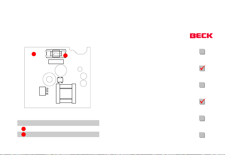
G
Figure 2
G
Power supply board
I
800 mA fu se, slow-acting (T 800)
®
IPC FEC
The FEC FC21 and FEC FC23 modules are equipped with a power supply fuse (800 mA, slow-
I
acting) and a 315 mA main board fuse (slowacting). Take care not to transpose the two
fuse ratings. Once the upper section of the
housing has been opened, the power supply
fuse can be seen on the power supply board in
the lower section of the housing (figure 2 - FEC
FC21 and FEC FC23 only).
FEC_ FCXX_ HE12 Version 1.2 as of 03.07.2000
FC20
FC21
FC22
FC23
FC30
FC34
Page 64
Page 65
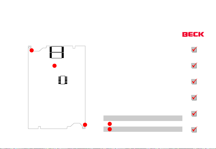
IPC FEC
To replace the fuse on the main board, the
J
main board must be removed from the upper
section of the housing. To do this, please undo
the two recessed-head screws shown in figure
G
3.
FC20
FC21
FC22
FC23
FC30
Figure 3
G
J
®
FEC_ FCXX_ HE12 Version 1.2 as of 03.07.2000
Main board
J
Recessed-head screws
Page 65
FC34
Page 66
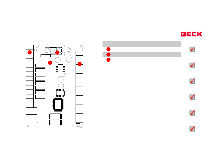
Figure 4
G
H
I
G
H
Main board
H
Screw te rminal connectio n
I
315 mA fu se, slow-act ing (T 315)
Now the board can be removed from the upper
section of the housing and the fuse removed
FC20
FC21
FC22
from its holder using a suitable tool (figure 4)
so that it can be replaced with a working 315
mA slow-acting glass fuse. Please take care to
FC23
hold the board only at the edges, and do not
touch any electronic components or conducting tracks. Assemble the components in reverse order when you are ready to close the
FC30
housing again. When assembly is complete,
the module can continue normal operation.
FC34
IPC FEC
®
FEC_ FCXX_ HE12 Version 1.2 as of 03.07.2000
Page 66
Page 67

Technical data
Climatic characteristics
Transportation/storage (IEC 68-2-1/2). . . . : -25ºC to +70ºC
Normal operation (IEC 68-2-1/2).. . . . . : 0ºC to +55ºC / 20 G
Temperature change (slow change). . . . . : IEC 68-2-14
Relative humidity (DIN 40040). . . . . . : up to 95% no condensing
Mechanical characteristics
Weight . . . . .... ..: approx. 160 g
Dimensions (FC21/FC23) ......: 130 x 80 x 60 mm
Dimensions (FC20/FC22/FC30/FC34) . . . . : 130 x 80 x 35 mm
Vibration (sinusoidal oscillation) . . . . . : IEC 68-2-6; 10 to 57 Hz: 0,075 mm
constant amplitude 57 to 150 Hz:
1,0 constant acceleration
IPC FEC
®
FEC_ FCXX_ HE12 Version 1.2 as of 03.07.2000
Page 67
Page 68

Shock load (IEC 68-2-27)) . . . . . : 11 ms, up to 15 g
Electromagnetic characteristics
Electromagnetic compatibility, noise gating. . : EN 50081-2
Electromagnetic compatibility, resistance
to jamming. . . . . . . . . : EN 61000-6-2 accord. IEC 61000-6-2;
in accordance with EN 1131-2
Electrostatic discharge (ESD). . . . . : EN 61000-4-2 accord. IEC 1000-4-2
High frequency electromagnetic fields (HFF). . : EN 61000-4-3 accord. IEC 1000-4-3
Fast transients (BURST). . . . . . : EN 61000-4-4 accord. IEC 1000-4-4
Wire-conducted HF interference (LHF). . . : EN 61000-4-6 accord. IEC 1000-4-6
Radio interference / interference strength. . : EN 55022 / A
Electrical characteristics:
Maximum current consumption (at 5 V). . . : 300 mA (typical)
Power consumption. . . . . . . : 1.6 W (typical)
IPC FEC
®
FEC_ FCXX_ HE12 Version 1.2 as of 03.07.2000
Page 68
Page 69

Inputs:
Galvanic separation . ......: Optocoupler
Input voltage . . . ......: 24 V DC, input current 7mA
Delay time . . . .... ..: 5 ms
Signal display . . .... ..: Green LED (after galv. separation)
2 fast counter inputs . ......: max. 2 kHz
Incremental encoder . .... ..: max. 200 Hz
Transistor outputs:
Supply voltage, output group (C+/C-) . . . : +19 V to +24 V DC, 24 V nominal
Nominal load capacity . ......: 600 mA 24 V DC
Service life . . . ......: 100,000 hours
Maximum switching frequency . . . . . : 1 kHz
Relay outputs: (PCB relays)
IPC FEC
®
FEC_ FCXX_ HE12 Version 1.2 as of 03.07.2000
Page 69
Page 70

Supply voltage, output group (C+/C-) . . . : +19 V to +24 V DC, 24 V nominal
Nominal load capacity . . . . . . : 5A / 250V AC, 5 A / 30 V DC
Service life . . . . . . . . . : 100,000 switching operations at nominal
load minimum load: 10 mA at 5 V DC
Maximum switching frequency . . . . . . : 25 Hz
Solid-state relays
Supply voltage, output group (C+/C-) . . . : +19 V to +28 V DC, 24 V nominal
Nominal load capacity . . . . . . : 0.1 to 600 mA 3 to 264 V AC; 3 to 125 V DC
Service life . . . . . . . . . : 100,000 hours
Maximum switching frequency . . . . . : 10 Hz
Safety information
Protective system . . . . . . . . : IP 40
Protective class. . . . . . . . . : III
Dimensioning of insulation . . . . . . : EN60950 accord. IEC 950
IPC FEC
®
FEC_ FCXX_ HE12 Version 1.2 as of 03.07.2000
Page 70
Page 71

Dielectric strength against internal system voltage:
Digital inputs.........: Supply voltage with reliable isolation
from mains voltage; isolation
voltage rating: 50 V AC
Digital transistor outputs .... ..: Supply voltage with basic isolation
from mains voltage; isolation
voltage rating: 300 V AC
Digital relay outputs . ......: Mains voltage of overload category
II can be switched; isolation voltage
IPC FEC
®
FEC_ FCXX_ HE12 Version 1.2 as of 03.07.2000
Page 71
Page 72

rating: 300 V AC
Digital solid-state relay outputs . . . . . : Mains voltage in overload category I can be
switched; isolation voltage rating: 300V AC
Hardware and software characteristics
Processor . . . . . . . . . : AM186 (20 MHZ), (Intel 80186-compati
ble)
Program memory FC30/34 (compiled) . . . : 512 kB 8-bit Flash (read/write cycles:
10,000)
RAM (FC30/FC34) . . . . . . . . : 512 kB 16-bit DRAM, (480 kB free)
RAM (FC20, 21, 22, 23) . . . . . . . : 256 kB 16-bit SRAM (210 kB free)
Remanent data . . . . . . . . : 2 kB in Flash
Terminal connection (FC30/FC34) . . . . : Serial asynchronous TTL (RJ12 connector)
Terminal connection (FC20, 21, 22, 23) . . . : RS232 3-wire 9600 baud (mini RJ11 con
nector)
IPC FEC
®
FEC_ FCXX_ HE12 Version 1.2 as of 03.07.2000
Page 72
Page 73

Operating status indicator .......: Status LED (green, red, orange)
Operating system . . .... ...: ROM DOS 5.0
Network connection (FC34) .......: 10BASE T (RJ45)
Network communication indicator (FC34) . . . . : Link/Traffic LED
IPC FEC
®
FEC_ FCXX_ HE12 Version 1.2 as of 03.07.2000
Page 73
Page 74

Ordering information
Typ Best.no.
FEC FC20-DOS FEC 12 inputs/8 relay outputs, 24 V DC, DOS 184334
FEC FC20-FST FEC 12 inputs/8 relay outputs, 24 V DC, FST 177428
FEC FC20-ICL FEC 12 inputs/8 relay outputs, 24 V DC, iCon-L 190575
FEC FC20-IEC FEC 12 inputs/8 relay outputs, 24 V DC, IEC6113-3l SaGRAF 185194
FEC FC21-DOS FEC 12 inputs/8 relay outputs, 110/230 V AC, DOS 184335
FEC FC21-FST FEC 12 inputs/8 relay outputs, 110/230 V AC, FST 177429
FEC FC21-ICL 190573
FEC FC21-IEC FEC 12 inputs/8 relay outputs, 110/230 V AC, IEC61131-3lSaGRAF 185210
FEC FC22-FST FEC 12 inputs/8 relay outputs, 24 V DC, FST 184332
FEC FC23-FST FEC 12 inputs/8 relay outputs, 110/230 V AC, FST 184333
FEC FC30-DOS FEC 12 inputs/2 relays, 6 transistor outputs, 24 V AC, DOS 185199
®
IPC FEC
Command
FEC 12 inputs/8 relay outputs, 110/230 V AC, iCon-L
FEC_ FCXX_ HE12 Version 1.2 as of 03.07.2000
Page 74
Page 75

FEC FC30-FST FEC 12 inputs/2 relays, 6 transistor outputs, 24 V DC, FST 183861
FEC FC30-ICL FEC 12 inputs/2 relays, 6 transistor outputs, 24 V DC, iCon-L 19057 8
FEC FC30-MWT FEC 12 inputs/2 relays, 6 transistor outputs, 24 V DC, IEC61131- 3MWT 19 0574
FEC FC34-DOS FEC 12 inputs/2 relays, 6 transistor outputs, 24 V DC, Ethern.10BaseT, DOS 190585
FEC FC34-FST FEC 12 inputs/2 relays, 6 transistor outputs, 24 V DC, Ethern.10BaseT, FST 190587
FEC FC34-ICL
FEC FC34-MWT FEC 12 inputs/2 relays, 6 transistor outputs, 24 V DC, Ethern.10BaseT, MWT 191448
PS1 SM14 PC prog./com. cable RS12/TTL-RS232/9-SUBD 188935
FEC KSD1 Service adapter (15 cm) RJ 11/9-SUBD 177432
FEC KSD2 PC prog./com. cable (150 c m) RJ11/9-SUBD 177431
FEC KSD4 Network cable for 2 stat ions (30 cm) R J12/RJ1 2 183635
PS1 ZK44 Module cable AW G26, 8-core for RJ4 5 (100 meters) 189682
PS1 ZC24 Modul ar connector RJ4 5, 8-pin (10) 190580
FEC 12 inputs/2 relays, 6 transistor outputs, 24 V DC, Ethern.10BaseT, iCon-L
191447
IPC FEC
®
FEC_ FCXX_ HE12 Version 1.2 as of 03.07.2000
Page 75
Page 76

We try to keep our manuals up to date at all
times. If you discover descriptions that are difficult to understand or even contain errors,
please inform us, specifying the manual concerned and the version number to the following E-mail address (Internet):
Please also send your suggestions and improvements.
We cannot reply to technical queries by E-mail.
Please contact your retailer.
More information under:
http://www.beck-ipc.com
IPC FEC
®
FEC_ FCXX_ HE12 Version 1.2 as of 03.07.2000
Page 76
Page 77

Notes
IPC FEC
®
FEC_ FCXX_ HE12 Version 1.2 as of 03.07.2000
Page 77
 Loading...