

Page 1
USER MANUAL
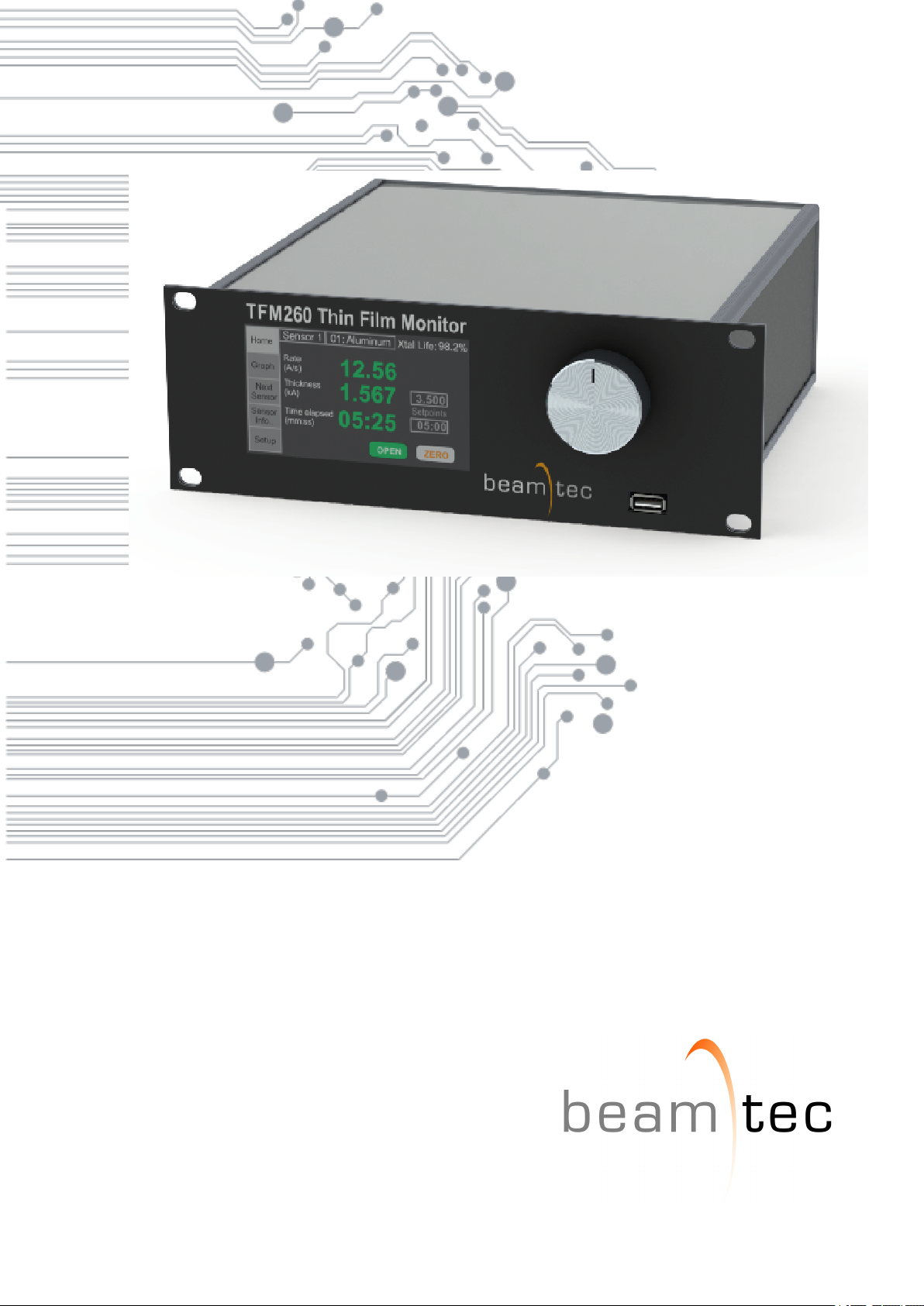
Thin Film Monitor TFM260
rev 1.0
Page 2

Page 3

Contents
1 INTRODUCTION 9
1.1 INTENDED TO USE . . . . . . . . . . . . . . . . . . . . . . . . . . . . . . . . . . 9
1.2 LIABILITIES AND WARRANTY . . . . . . . . . . . . . . . . . . . . . . . . . . . . 9
1.3 INSTRUMENT SAFETY . . . . . . . . . . . . . . . . . . . . . . . . . . . . . . . . 9
1.3.1 DEFINITION OF NOTES, CAUTIONS AND WARNINGS . . . . . . . . . 9
1.3.2 PERSONNEL QUALIFICATIONS . . . . . . . . . . . . . . . . . . . . . . . 10
1.3.3 GENERAL SAFETY INSTRUCTIONS . . . . . . . . . . . . . . . . . . . . 11
2 TECHNICAL DATA 13
2.1 Rack Mounting Options . . . . . . . . . . . . . . . . . . . . . . . . . . . . . . . . 13
2.2 EXTERNAL DIMENSIONS . . . . . . . . . . . . . . . . . . . . . . . . . . . . . . 16
2.3 INITIAL POWER-ON VERIFICATION . . . . . . . . . . . . . . . . . . . . . . . . 17
3 INSTALLATION 18
3.1 UNPACKING . . . . . . . . . . . . . . . . . . . . . . . . . . . . . . . . . . . . . . 18
3.1.1 PACKAGE CONTENTS . . . . . . . . . . . . . . . . . . . . . . . . . . . . 19
3.2 INSTALLATION REQUIREMENTS . . . . . . . . . . . . . . . . . . . . . . . . . . 19
3.3 FRONT PANEL . . . . . . . . . . . . . . . . . . . . . . . . . . . . . . . . . . . . . 20
3.4 REAR PANEL . . . . . . . . . . . . . . . . . . . . . . . . . . . . . . . . . . . . . . 20
3.4.1 SENSOR 1-6 [1] . . . . . . . . . . . . . . . . . . . . . . . . . . . . . . . . 21
3.4.2 RS-232 [2] . . . . . . . . . . . . . . . . . . . . . . . . . . . . . . . . . . . 21
3.4.3 POWER CONNECTOR AND FUSE AND ON/OFF SWITCH [4] . . . . . . 22
3.4.4 ANALOGUE OUTPUTS 1-6 [5] . . . . . . . . . . . . . . . . . . . . . . . . 22
3.4.5 QM MODULES [6] . . . . . . . . . . . . . . . . . . . . . . . . . . . . . . . 23
3.4.6 Relay I/O [7] . . . . . . . . . . . . . . . . . . . . . . . . . . . . . . . . . . 25
3.5 SYSTEM CONNECTIONS . . . . . . . . . . . . . . . . . . . . . . . . . . . . . . 26
3.6 EXTERNAL OSCILLATOR . . . . . . . . . . . . . . . . . . . . . . . . . . . . . . 28
4 OPERATION 30
4.1 EDIT VALUES . . . . . . . . . . . . . . . . . . . . . . . . . . . . . . . . . . . . . 30
4.2 MAIN SCREEN . . . . . . . . . . . . . . . . . . . . . . . . . . . . . . . . . . . . . 30
4.2.1 HOME WINDOW . . . . . . . . . . . . . . . . . . . . . . . . . . . . . . . . 31
4.3 SETUP MENU . . . . . . . . . . . . . . . . . . . . . . . . . . . . . . . . . . . . . 32
4.3.1 SENSOR TOOLING FACTOR . . . . . . . . . . . . . . . . . . . . . . . . 32
4.3.2 FIFO FILTER . . . . . . . . . . . . . . . . . . . . . . . . . . . . . . . . . . 33
4.3.3 RATE FILTER ALPHA . . . . . . . . . . . . . . . . . . . . . . . . . . . . . 34
4.3.4 MEASURMENT PERIOD . . . . . . . . . . . . . . . . . . . . . . . . . . . 35
4.3.5 CRYSTAL FREQUENCY MIN/MAX . . . . . . . . . . . . . . . . . . . . . 35
4.3.6 COMMUNICATIONS . . . . . . . . . . . . . . . . . . . . . . . . . . . . . . 36
3
Page 4

4.3.7 ANALOGUE OUTPUTS . . . . . . . . . . . . . . . . . . . . . . . . . . . . 37
4.3.8 RELAY OUTPUTS . . . . . . . . . . . . . . . . . . . . . . . . . . . . . . . 38
4.3.9 ASSIGNING INPUTS . . . . . . . . . . . . . . . . . . . . . . . . . . . . . 39
4.3.10 ADVANCED SETTINGS . . . . . . . . . . . . . . . . . . . . . . . . . . . . 40
4.3.11 EXTERNAL CHANNEL . . . . . . . . . . . . . . . . . . . . . . . . . . . . 41
4.3.12 INFORMATION . . . . . . . . . . . . . . . . . . . . . . . . . . . . . . . . . 43
4.4 MATERIAL LIST . . . . . . . . . . . . . . . . . . . . . . . . . . . . . . . . . . . . 43
4.4.1 ADD MATERIAL . . . . . . . . . . . . . . . . . . . . . . . . . . . . . . . . 43
4.4.2 EDIT MATERIAL . . . . . . . . . . . . . . . . . . . . . . . . . . . . . . . . 44
4.4.3 DELETE MATERIAL . . . . . . . . . . . . . . . . . . . . . . . . . . . . . . 44
4.5 FILM MENU . . . . . . . . . . . . . . . . . . . . . . . . . . . . . . . . . . . . . . . 44
4.5.1 RATE SAMPLING . . . . . . . . . . . . . . . . . . . . . . . . . . . . . . . 45
4.6 SENSOR INFO MENU . . . . . . . . . . . . . . . . . . . . . . . . . . . . . . . . . 45
5 OPERATION - REMOTE CONTROL 47
5.1 RS232 COMMUNICATION . . . . . . . . . . . . . . . . . . . . . . . . . . . . . . 47
5.2 ETHERNET PORT . . . . . . . . . . . . . . . . . . . . . . . . . . . . . . . . . . . 47
5.3 COMMUNICATIONS PROTOCOL . . . . . . . . . . . . . . . . . . . . . . . . . . 48
5.4 COMMAND PACKET . . . . . . . . . . . . . . . . . . . . . . . . . . . . . . . . . 48
5.5 RESPONSE PACKET . . . . . . . . . . . . . . . . . . . . . . . . . . . . . . . . . 48
5.6 CALCULATING THE CRC . . . . . . . . . . . . . . . . . . . . . . . . . . . . . . . 49
5.7 COMMANDS LIST . . . . . . . . . . . . . . . . . . . . . . . . . . . . . . . . . . . 50
6 TROUBLESHOOTING 52
7 CALIBRATION PROCEDURES 57
7.1 IMPORTANCE OF DENSITY, TOOLING AND Z-RATIO . . . . . . . . . . . . . . 57
7.2 DETERMINING DENSITY . . . . . . . . . . . . . . . . . . . . . . . . . . . . . . . 57
7.3 DETERMINING TOOLING . . . . . . . . . . . . . . . . . . . . . . . . . . . . . . 58
7.4 Laboratory Determination of Z-Ratio . . . . . . . . . . . . . . . . . . . . . . . . . 58
8 Measurement and Theory 60
8.1 TOLLING FACTOR . . . . . . . . . . . . . . . . . . . . . . . . . . . . . . . . . . . 61
8.2 MATERIAL LIST . . . . . . . . . . . . . . . . . . . . . . . . . . . . . . . . . . . . 62
9 MAINTANCE AND SERVICE 72
9.1 MAINTANCE . . . . . . . . . . . . . . . . . . . . . . . . . . . . . . . . . . . . . . 72
9.2 CLEANING . . . . . . . . . . . . . . . . . . . . . . . . . . . . . . . . . . . . . . . 72
9.3 CHECK FOR CORRECT OPERATION - TEST QUARTZ . . . . . . . . . . . . . 72
9.4 FIRMWARE UPDATE . . . . . . . . . . . . . . . . . . . . . . . . . . . . . . . . . 72
9.4.1 DOWNLOAD FIRMWARE FILE . . . . . . . . . . . . . . . . . . . . . . . . 72
9.4.2 DEVICE BOOT-LOADER MODE . . . . . . . . . . . . . . . . . . . . . . . 73
9.4.3 FIRMWARE UPDATE PROCEDURE . . . . . . . . . . . . . . . . . . . . . 73
4
Page 5

10 STORAGE AND DISPOSAL 74
10.1 PACKING . . . . . . . . . . . . . . . . . . . . . . . . . . . . . . . . . . . . . . . . 74
10.2 STORAGE . . . . . . . . . . . . . . . . . . . . . . . . . . . . . . . . . . . . . . . 74
10.3 DISPOSAL . . . . . . . . . . . . . . . . . . . . . . . . . . . . . . . . . . . . . . . 74
10.3.1 Waste Electrical and Electronic Equipment (WEEE) . . . . . . . . . . . . 74
11 WARRANTY CONDITIONS 76
5
Page 6

List of Tables
2.1 Technical specifications . . . . . . . . . . . . . . . . . . . . . . . . . . . . . . . . 13
2.2 IO Interface Parameters . . . . . . . . . . . . . . . . . . . . . . . . . . . . . . . . 14
2.3 Power . . . . . . . . . . . . . . . . . . . . . . . . . . . . . . . . . . . . . . . . . . 14
2.4 Operating Environment . . . . . . . . . . . . . . . . . . . . . . . . . . . . . . . . 14
2.5 Dimensions & Weight . . . . . . . . . . . . . . . . . . . . . . . . . . . . . . . . . 14
2.6 Film Parameters . . . . . . . . . . . . . . . . . . . . . . . . . . . . . . . . . . . . 15
3.1 Package set . . . . . . . . . . . . . . . . . . . . . . . . . . . . . . . . . . . . . . . 19
3.2 RS232 connector - Pin functions and descriptions . . . . . . . . . . . . . . . . . 21
3.3 RJ-45 Connector Pinout(Data & Power) . . . . . . . . . . . . . . . . . . . . . . . 22
3.4 Relay I/O - Pin functions and descriptions . . . . . . . . . . . . . . . . . . . . . . 26
4.1 Analogue outputs functions . . . . . . . . . . . . . . . . . . . . . . . . . . . . . . 38
4.2 Relay outputs function . . . . . . . . . . . . . . . . . . . . . . . . . . . . . . . . . 39
4.3 Digital inputs function . . . . . . . . . . . . . . . . . . . . . . . . . . . . . . . . . 40
5.1 Command packet - field descriptions . . . . . . . . . . . . . . . . . . . . . . . . . 48
5.2 Response packet - field descriptions . . . . . . . . . . . . . . . . . . . . . . . . . 49
5.3 TFM260 commands . . . . . . . . . . . . . . . . . . . . . . . . . . . . . . . . . . 51
6.1 Write device address . . . . . . . . . . . . . . . . . . . . . . . . . . . . . . . . . . 56
8.1 Material table . . . . . . . . . . . . . . . . . . . . . . . . . . . . . . . . . . . . . . 71
10.1 Storage parameters . . . . . . . . . . . . . . . . . . . . . . . . . . . . . . . . . . 74
6
Page 7

List of Figures
2.1 TFM260 external dimensions . . . . . . . . . . . . . . . . . . . . . . . . . . . . . 16
2.2 External dimensions External oscillator(EO) . . . . . . . . . . . . . . . . . . . . . 17
2.3 Main screen . . . . . . . . . . . . . . . . . . . . . . . . . . . . . . . . . . . . . . . 17
3.1 TFM260 front panel . . . . . . . . . . . . . . . . . . . . . . . . . . . . . . . . . . 20
3.2 TFM260 external dimensions . . . . . . . . . . . . . . . . . . . . . . . . . . . . . 20
3.3 RS232 connector (D-sub female 9 pin ) . . . . . . . . . . . . . . . . . . . . . . . 21
3.4 Power connector module . . . . . . . . . . . . . . . . . . . . . . . . . . . . . . . 21
3.5 Power connector module . . . . . . . . . . . . . . . . . . . . . . . . . . . . . . . 22
3.6 External QMB6 module - RS232 . . . . . . . . . . . . . . . . . . . . . . . . . . . 24
3.7 External QMB6 module - RS485 . . . . . . . . . . . . . . . . . . . . . . . . . . . 25
3.8 RS232 connector (D-sub male 15 pin ) . . . . . . . . . . . . . . . . . . . . . . . 25
3.9 System connection - example diagram . . . . . . . . . . . . . . . . . . . . . . . . 26
3.10 QMB6-EO connectors . . . . . . . . . . . . . . . . . . . . . . . . . . . . . . . . . 29
4.1 Edit Values . . . . . . . . . . . . . . . . . . . . . . . . . . . . . . . . . . . . . . . 30
4.2 Main Screen Buttons . . . . . . . . . . . . . . . . . . . . . . . . . . . . . . . . . . 31
4.3 TFM260 Home Screen . . . . . . . . . . . . . . . . . . . . . . . . . . . . . . . . 31
4.4 Unit change example screen . . . . . . . . . . . . . . . . . . . . . . . . . . . . . 32
4.5 Setup menu . . . . . . . . . . . . . . . . . . . . . . . . . . . . . . . . . . . . . . . 32
4.6 Toolng Factor submenu . . . . . . . . . . . . . . . . . . . . . . . . . . . . . . . . 33
4.7 FIFO filter submenu . . . . . . . . . . . . . . . . . . . . . . . . . . . . . . . . . . 34
4.8 Alpha filter submenu . . . . . . . . . . . . . . . . . . . . . . . . . . . . . . . . . . 34
4.9 Alpha filtering diagram . . . . . . . . . . . . . . . . . . . . . . . . . . . . . . . . . 34
4.10 Measurment peroid submenu . . . . . . . . . . . . . . . . . . . . . . . . . . . . . 35
4.11 Crystal Min/Max submenu . . . . . . . . . . . . . . . . . . . . . . . . . . . . . . . 35
4.12 Serial interface and Ethernet parameters . . . . . . . . . . . . . . . . . . . . . . 36
4.13 Analogue Outputs Submenu . . . . . . . . . . . . . . . . . . . . . . . . . . . . . 38
4.14 Relay Outputs Submenu . . . . . . . . . . . . . . . . . . . . . . . . . . . . . . . . 38
4.15 Digital Inputs Submenu . . . . . . . . . . . . . . . . . . . . . . . . . . . . . . . . 39
4.16 Configuration Submenu . . . . . . . . . . . . . . . . . . . . . . . . . . . . . . . . 40
4.17 External channel configuration Submenu . . . . . . . . . . . . . . . . . . . . . . 41
4.18 External channels avalible on Sensor List . . . . . . . . . . . . . . . . . . . . . . 42
4.19 External channels avalible on Setup menu(example) . . . . . . . . . . . . . . . . 42
4.20 Material Menu Buttons . . . . . . . . . . . . . . . . . . . . . . . . . . . . . . . . . 43
4.21 Material Menu . . . . . . . . . . . . . . . . . . . . . . . . . . . . . . . . . . . . . 43
4.22 Add Material . . . . . . . . . . . . . . . . . . . . . . . . . . . . . . . . . . . . . . 44
4.23 Edit Material . . . . . . . . . . . . . . . . . . . . . . . . . . . . . . . . . . . . . . 44
4.24 Film menu . . . . . . . . . . . . . . . . . . . . . . . . . . . . . . . . . . . . . . . . 45
7
Page 8

TFM260 Thin Film Monitor 8
4.25 Sensor Info . . . . . . . . . . . . . . . . . . . . . . . . . . . . . . . . . . . . . . . 46
8.1 Tooling factor over 100% . . . . . . . . . . . . . . . . . . . . . . . . . . . . . . . 61
8.2 Tooling factor under 100% . . . . . . . . . . . . . . . . . . . . . . . . . . . . . . . 62
10.1 Waste Electrical and Electronic Equipment (WEEE) Symbol . . . . . . . . . . . . 75
Wolfgang-Paul-Str. 4, 89081 Ulm, Germany
BeamTec
Page 9

9 TFM260 Thin Film Monitor
1 INTRODUCTION
Please read this manual carefully to ensure optimum operating conditions right from the start.
This user manual handbook contains important information about the functionality, installation,
start-up and operation of the Thin Film Monitor TFM260 .
1.1 INTENDED TO USE
TFM260 uses quartz crystal sensor technology to measure rate and thickness in a thin film deposition process. Two sensor inputs are standard and four additional sensor inputs are optional.
Six recorder outputs provide both analog rate, thickness or frequency signals.
Sensor inputs are assigned to different materials, averaged for accurate deposition control in
large systems or configured for a dual sensor. The rate sampling mode allows a shuttered sensor to extend sensor life in high rate processes. Rate displays of 0.01 Å/s. In addition, frequency
or mass displays can be selected. Four relay outputs allow TFM260 to control source or sensor shutters, signal time and thickness setpoints, and signal crystal failure. Digital inputs allow
external signals to start/stop and zero readings. TFM260 comes with an RS-232 and Ethernet
port. The implemented protocol is compatible with Inficon SQM-160 and you can use the same
software to operate the TFM260 . The software can be used to set and store all parameters,
operate TFM260 and save process data in a .txt file that can be imported into Excel.
1.2 LIABILITIES AND WARRANTY
BeamTec company is not liable for damages resulting from improper use of the device and the
guarantee expires, if the user, or third party:
• ignores information contained in this manual,
• utilizes the product in a manner inconsistent with intended purpose,
• makes any modification or alteration of the product,
• unit should not be used with unauthorized accessories (compatible accessories, types
and models can be found in the product documentation)
BeamTec company reserves the right to make changes without prior notice. Illustrations may
vary depending on the version of the device.
1.3 INSTRUMENT SAFETY
1.3.1 DEFINITION OF NOTES, CAUTIONS AND WARNINGS
When using this manual, please pay attention to the notes, cautions and warnings found throughout. For the purposes of this manual they are defined as follows:
NOTE: Pertinent information that is useful in achieving maximum TFM260 efficiency when followed.
www.beamtec.de ; e-mail: [email protected] tel.: +49 731 146620 0
Wolfgang-Paul-Str. 4, 89081 Ulm, Germany
BeamTec
Page 10
TFM260 Thin Film Monitor 10
CAUTION
Indicates particularly important, but not safety-relevant information.
Failure to heed these messages could result in damage to TFM260 or the loss
of data.
WARNING
Failure to heed these messages could result in personal injury.
Information on correct handling or use. Disregarding safety notes can lead to
malfunctions.
1.3.2 PERSONNEL QUALIFICATIONS
All work described in this document may only be carried out by persons who have suitable
technical training and the necessary experience or who have been instructed by the end user
of the product.
www.beamtec.de ; e-mail: [email protected] tel.: +49 731 146620 0
Wolfgang-Paul-Str. 4, 89081 Ulm, Germany
BeamTec
Page 11
11 TFM260 Thin Film Monitor
WARNING
Risk Of Electric Shock
Dangerous voltages are present, which could result in personal injury.
1.3.3 GENERAL SAFETY INSTRUCTIONS
CAUTION
TFM260 contains delicate circuitry, susceptible to transient power line
voltages. Disconnect the power cord whenever making any sensor connections
CAUTION
TFM260 may not be suitable for use with RF sputtering systems or other
electrically noisy environments.
For all work you are going to do, adhere to the applicable safety regulations. Also observe all
safety notes given in this document and forward the information to all other users of the product.
www.beamtec.de ; e-mail: [email protected] tel.: +49 731 146620 0
Wolfgang-Paul-Str. 4, 89081 Ulm, Germany
BeamTec
Page 12
TFM260 Thin Film Monitor 12
CAUTION
Do not open the instrument case! There are no user-serviceable components within instrument case
Do not open the TFM260 case. Refer all maintenance to qualified personnel.
There are no user-serviceable components within the TFM260 case. Dangerous voltages may be present whenever the power cable or external input/relay
connectors are present.
CAUTION
TFM260 contains delicate circuitry
TFM260 contains delicate circuitry, susceptible to transient power line voltages. Disconnect the power cable whenever making any interface connections. Refer all maintenance to qualified personnel.
WARNING
Risk Of Electric Shock
TFM260 must be connected to earth ground through a sealed three-conductor
power cable plugged into a socket outlet with protective ground terminal.
Extension cables must have three conductors including a protective earth
ground.
WARNING
Failure to operate TFM260 in the manner intended by BeamTec can circumvent the safety protection provided by the instrument and may result in personal injury.
www.beamtec.de ; e-mail: [email protected] tel.: +49 731 146620 0
Wolfgang-Paul-Str. 4, 89081 Ulm, Germany
BeamTec
Page 13
13 TFM260 Thin Film Monitor
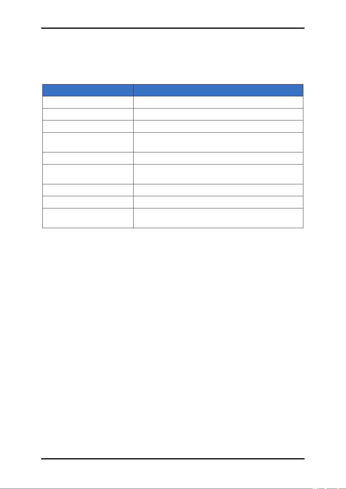
2 TECHNICAL DATA
PARAMETER VALUE
Frequency Resolution 0.01 Hz at 10 readings/s
Measurement Interval 0.1s to 2s (adjustable in 0.1s step)
Quartz oscillator type 6 MHz
Reference frequency stability
Sensor inputs 2(standard), up to 6(optional)
External sensor inputs 1 inputs RS232/RS485 (up to 3 devices working with
Input type female BNC
Protocol Compatible with INFICON SQM160 ASCII Protocol
Thickness and Rate Resolution/Measurement
0.5 ppm
RS485 interface)
±0.012 A @ tooling/density/z-ratio = 100/1/1, fundamental frequency = 6 MHz, 0.1s measurement interval
Table 2.1: Technical specifications
2.1 Rack Mounting Options
Rack mount kits allow one or two TFM260 instruments to be installed in a standard 48.3 cm (19
in.) rack. TFM260 is designed to mount in a standard 48.3 cm (19 in.) rack using optional rack
mount kits or can be used on a benchtop. Two rack mount kits are available:
• Full Rack Extender
• Rack Adapter
For detail information please contact the sales department of BeamTec .
www.beamtec.de ; e-mail: [email protected] tel.: +49 731 146620 0
Wolfgang-Paul-Str. 4, 89081 Ulm, Germany
BeamTec
Page 14
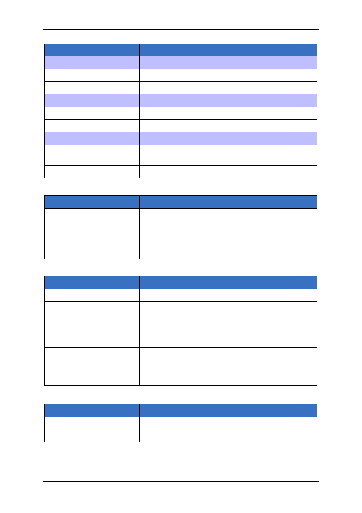
TFM260 Thin Film Monitor 14
PARAMETER VALUE
Digital inputs 4
Functions User-selected see chapter 4.3.9
Input rating 0-5V, non-isolated, active low(0 volts)
Relay outputs 4
Functions User-selected see chapter 4.3.8
Relay rating 30V(rms) or 30V (dc), 2A maximum
Analogue outputs 6
Functions Frequency, rate, thickness. User-selected see chapter
4.3.7 for detail information
Output rating 0-10V
Table 2.2: IO Interface Parameters
PARAMETER VALUE
Mains Power Supply 100 to 240V (ac), ±10% nominal, 50/60 Hz, autodetect
Power Consumption 45W
Fuse 250 V, 500 mA, Type T, 5 x 20 mm, time lag
Installation (Overvoltage) Class 1 Equipment (grounded type).
Table 2.3: Power
PARAMETER VALUE
Usage Use indoors only
Storage temperature -20...50°C
Operation temperature 15...40°C
Relative humidity 0 to 80 % RH non-condensing. Ordinary protection (not
protected against harmful ingress of moisture).
Altitude Up to 2000 meters
Pollution Degree 2 (per EN 61010)
Warm Up Period None required. For maximum stability allow 5 minutes.
Table 2.4: Operating Environment
PARAMETER VALUE
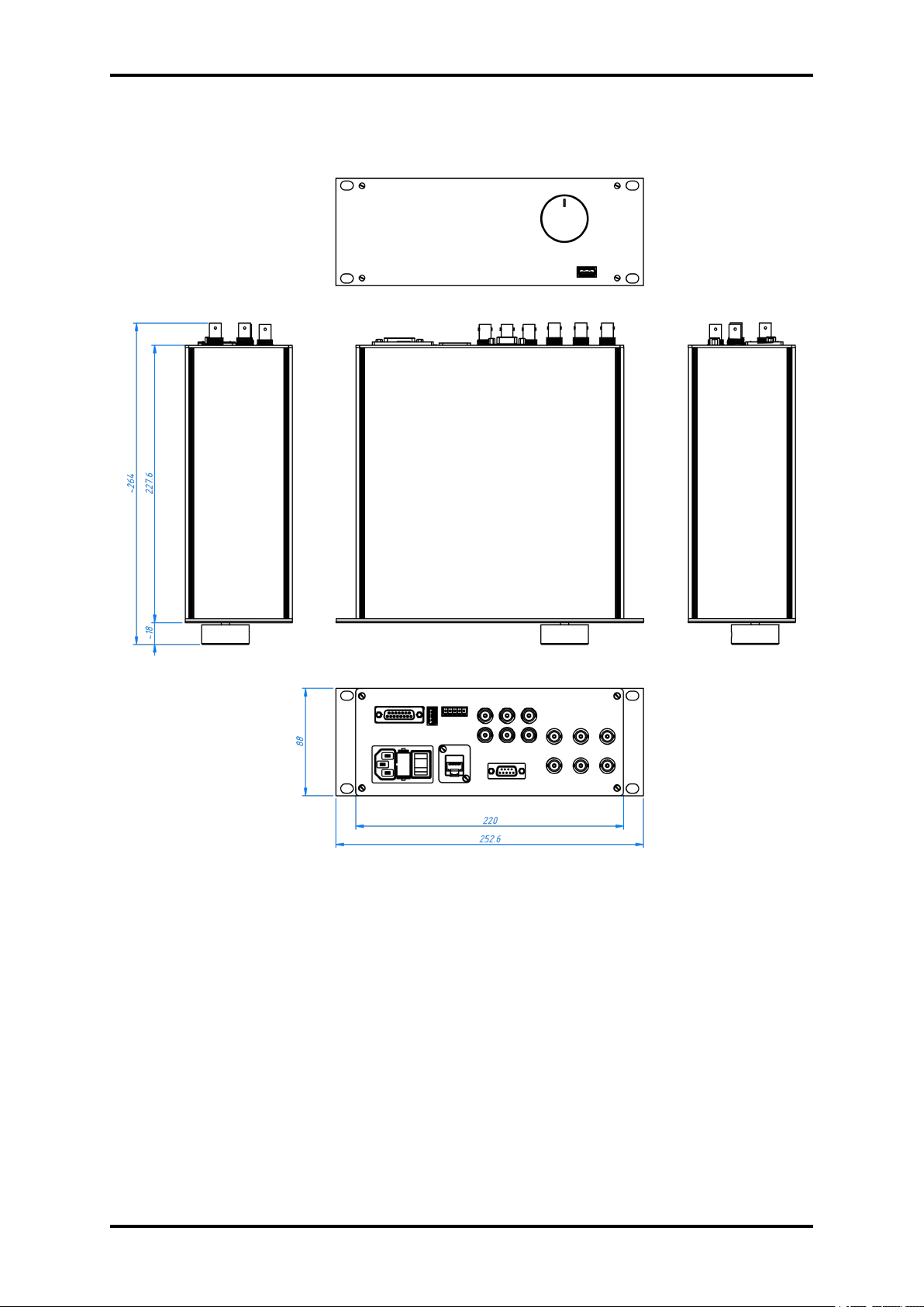
Case Dimensions H x W x D 88 x 252.6 x 264 mm
Weight 1.7 kg
Table 2.5: Dimensions & Weight
www.beamtec.de ; e-mail: [email protected] tel.: +49 731 146620 0
Wolfgang-Paul-Str. 4, 89081 Ulm, Germany
BeamTec
Page 15
15 TFM260 Thin Film Monitor
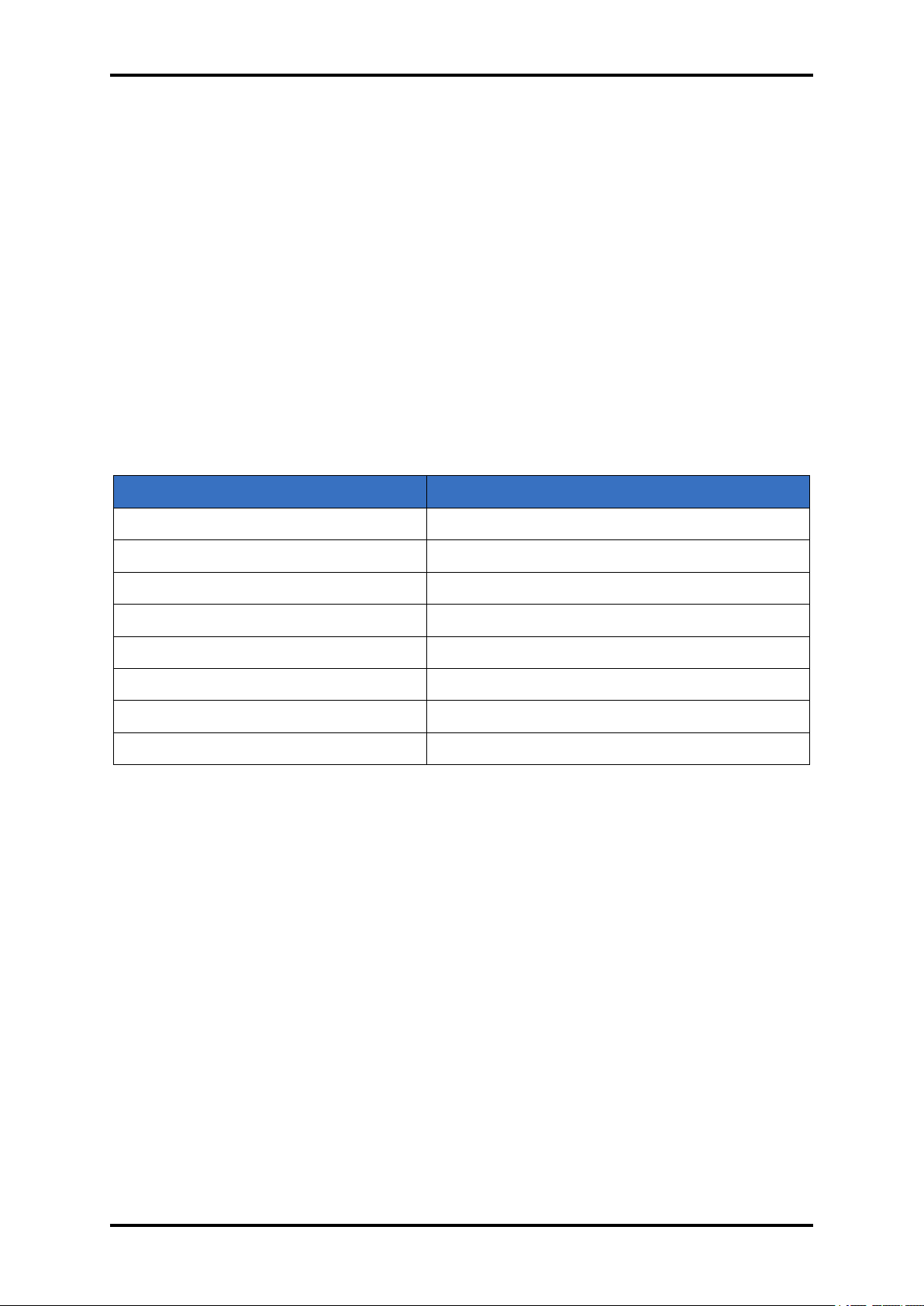
PARAMETER VALUE
Stored Films 99
Density 0.50 to 99.99 g/cm3
Tooling 10 to 399%
Acoustic impedance 0.10 to 10.00
Final Thickness 0.000 to 9999 kÅ
Time Setpoint 0:00 to 99:59 mm:ss
Sample/Hold. 0 to 5999 s
Sensor Average 1 to 6, depending on sensors installed
Table 2.6: Film Parameters
www.beamtec.de ; e-mail: [email protected] tel.: +49 731 146620 0
Wolfgang-Paul-Str. 4, 89081 Ulm, Germany
BeamTec
Page 16
TFM260 Thin Film Monitor 16
2.2 EXTERNAL DIMENSIONS
Figure 2.1: TFM260 external dimensions
www.beamtec.de ; e-mail: [email protected] tel.: +49 731 146620 0
Wolfgang-Paul-Str. 4, 89081 Ulm, Germany
BeamTec
Page 17
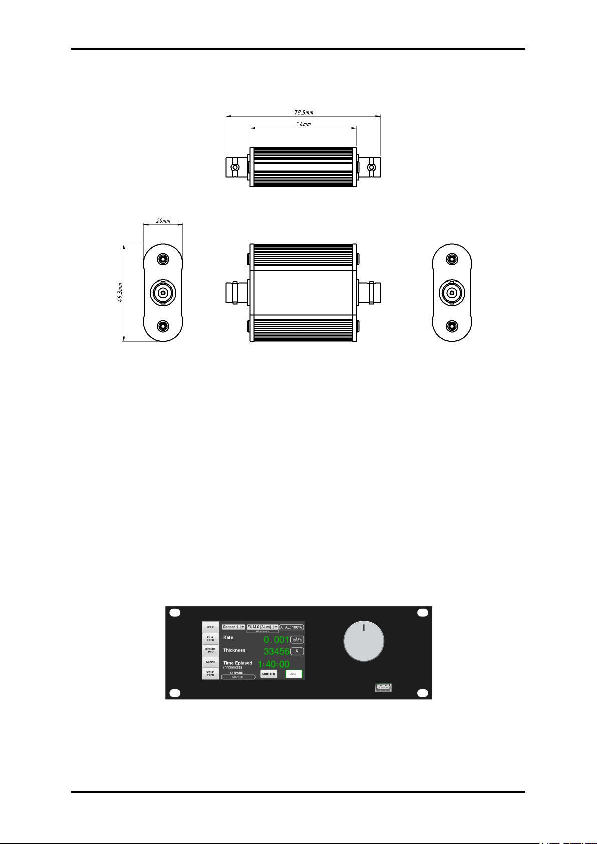
17 TFM260 Thin Film Monitor
TFM260 cooperating with QMB6-EO is the external oscillator and the dimensions shown below.
Figure 2.2: External dimensions External oscillator(EO)
2.3 INITIAL POWER-ON VERIFICATION
A preliminary functional check of TFM260 can be made before formal installation. It is not
necessary to have sensors, source controls, inputs, or relays connected to do this. For more
complete installation see chapter 3.
1. Confirm that the proper AC line mains voltage is supplied to TFM260 .
2. Confirm that the rear panel (main) AC switch is in the ON Position.
3. After the initial boot-up screen, TFM260 will display the main screen. This screen will be
similar to the screen displayed in figure 2.3.
Figure 2.3: Main screen
www.beamtec.de ; e-mail: [email protected] tel.: +49 731 146620 0
Wolfgang-Paul-Str. 4, 89081 Ulm, Germany
BeamTec
Page 18

TFM260 Thin Film Monitor 18
3 INSTALLATION
This chapter describes the procedures for unpacking, mechanical installation and electrical installation.
3.1 UNPACKING
1. If the TFM260 has not been removed from its packaging, do so now.
2. Carefully examine TFM260 for damage that may have occurred during shipping. It is
especially important to note obvious rough handling on the outside of the container. Immediately report any damage to the carrier and to BeamTec .
NOTE: Do not discard the packaging material until inventory has been taken and installation is successful.
3. Refer to the invoice and take inventory.
4. To install TFM260 , see next sections in this Chapter.
5. For additional information or technical assistance, contact BeamTec .
www.beamtec.de ; e-mail: [email protected] tel.: +49 731 146620 0
Wolfgang-Paul-Str. 4, 89081 Ulm, Germany
BeamTec
Page 19

19 TFM260 Thin Film Monitor
3.1.1 PACKAGE CONTENTS
Compare the contents of the package with the list below appropriate for your version of the
hardware device.
Description Quantity
TFM260 1 pcs.
Power cord 1.8m 1 pcs.
User Manual 1 pcs.
Table 3.1: Package set
3.2 INSTALLATION REQUIREMENTS
• TFM260 Monitor
• Crystal sensor with feedthrough
• Oscillator kit for the crystal sensor
• Quartz crystals appropriate for the application
www.beamtec.de ; e-mail: [email protected] tel.: +49 731 146620 0
Wolfgang-Paul-Str. 4, 89081 Ulm, Germany
BeamTec
Page 20
TFM260 Thin Film Monitor 20
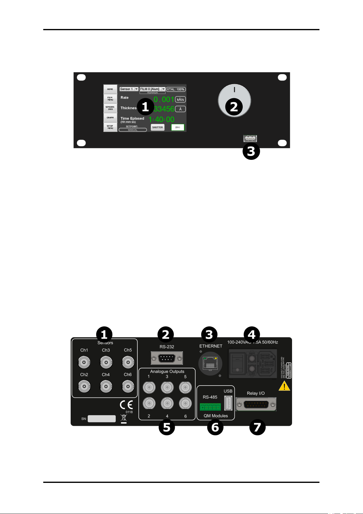
3.3 FRONT PANEL
Figure 3.1: TFM260 front panel
1. Screen
TFT screen 480x272 dpi. With integrated resistive touchscreen.
2. Control Knob
Used to adjust values and select menu items. The functions of the knob change to adapt
to different operations and are displayed on the the screen.
3. USB socket
USB type A socket. Allows to update the device by inserting a pendrive with firmware
files.
Allows to read/write device configuration and transfer it to another the same type device.
3.4 REAR PANEL
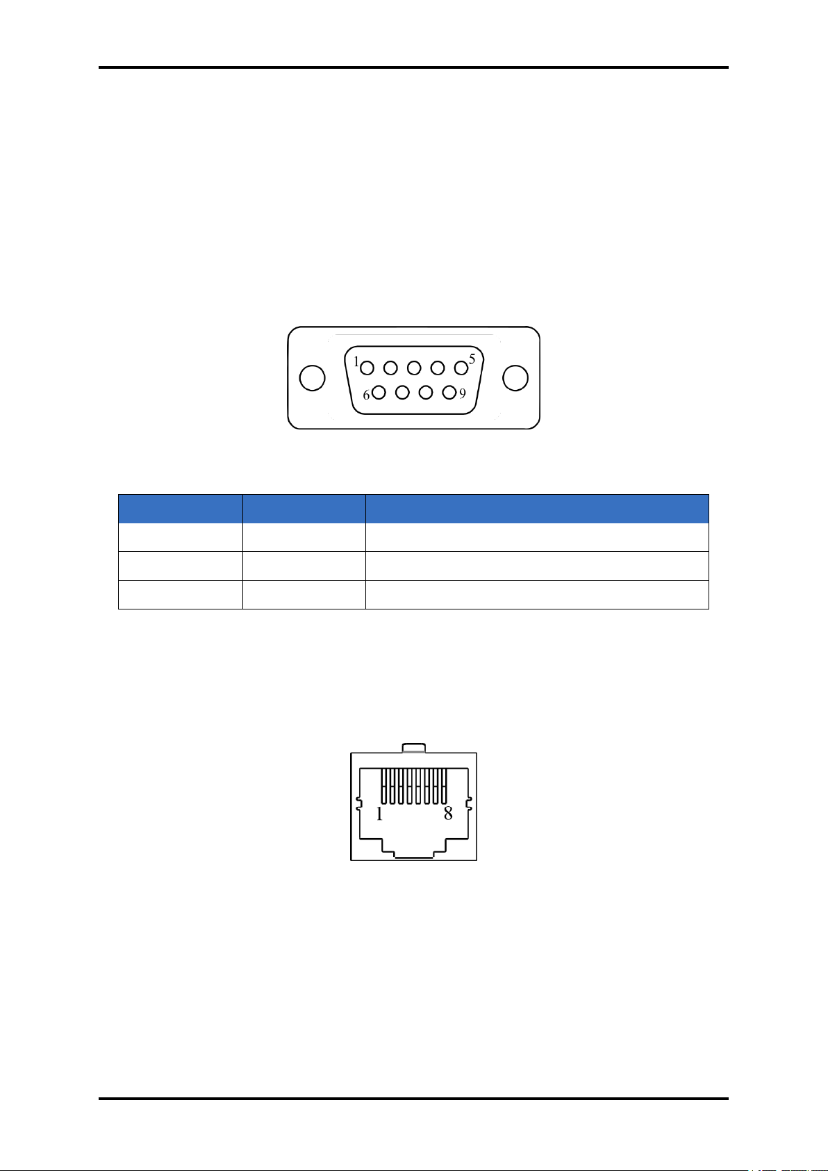
Figure 3.2: TFM260 external dimensions
www.beamtec.de ; e-mail: [email protected] tel.: +49 731 146620 0
Wolfgang-Paul-Str. 4, 89081 Ulm, Germany
BeamTec
Page 21
21 TFM260 Thin Film Monitor
3.4.1 SENSOR 1-6 [1]
BNC connection to the oscillators for sensors 1 to 6 (depending of device configuration, available version 2CH, 4CH and 6CH)
3.4.2 RS-232 [2]
Connection to computer for programming and data acquisition
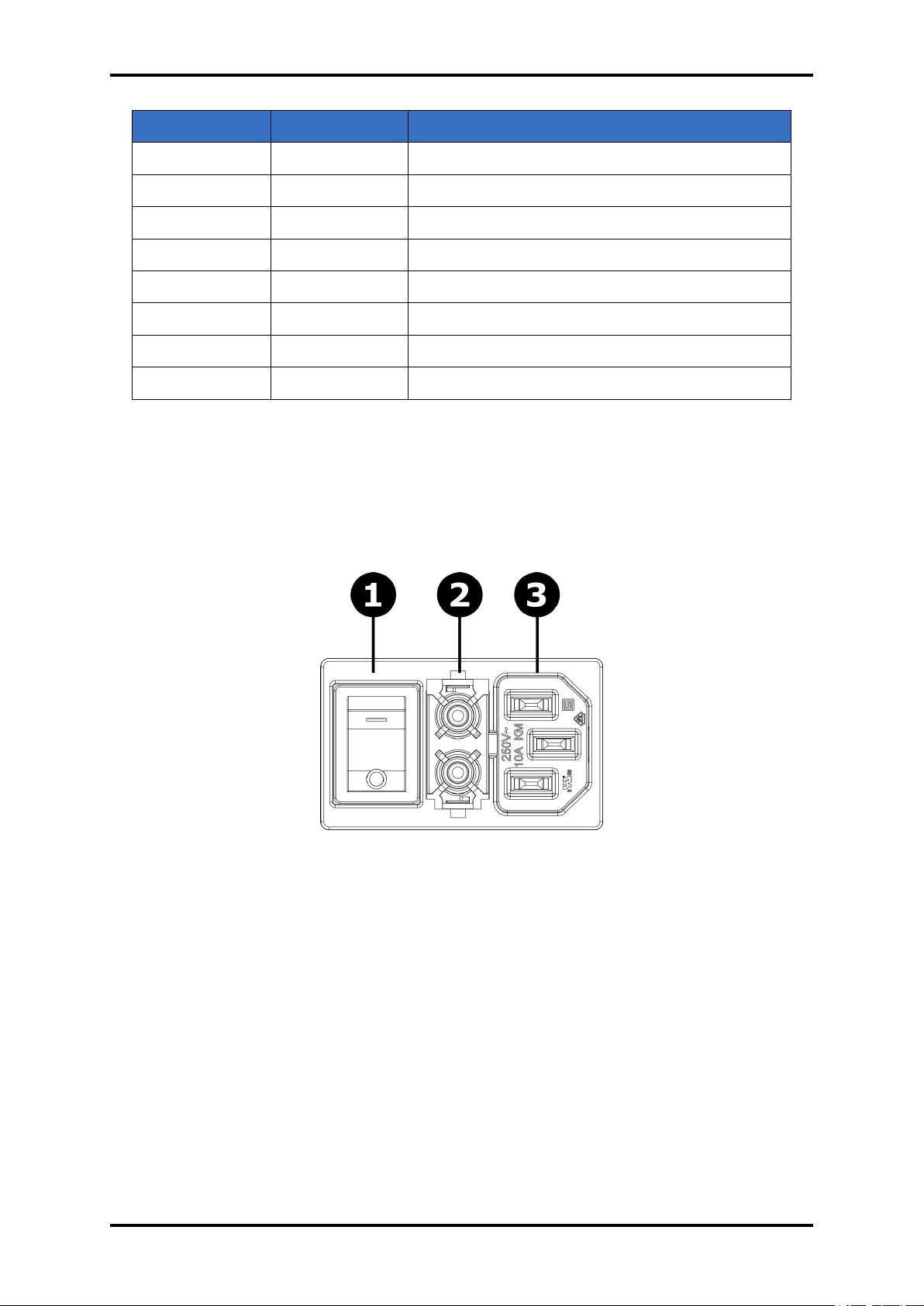
9 pin female d-sub type connector.
Figure 3.3: RS232 connector (D-sub female 9 pin )
PIN NUMBER FUNCTION DESCRIPTION
Pin 2 Rx Data input(receive line)
Pin 3 Tx Data output(transmit line)
Pin 5 GND Reference signal for data lines
Table 3.2: RS232 connector - Pin functions and descriptions
Ethernet port [3]
Connection to computer for programming and data acquisition. Detail information about port
configuration see section 4.3.6.
Figure 3.4: Power connector module
www.beamtec.de ; e-mail: [email protected] tel.: +49 731 146620 0
Wolfgang-Paul-Str. 4, 89081 Ulm, Germany
BeamTec
Page 22
TFM260 Thin Film Monitor 22
PIN NUMBER FUNCTION DESCRIPTION
Pin 1: RX+ Data receive(+)
Pin 2: RX- Data receive(-)
Pin 3: TX+ Data transmit(+)
Pin 4 n.c not connected
Pin 5 n.c not connected
Pin 6 TX- Data transmit(-)
Pin 7 n.c not connected
Pin 8 n.c not connected
Table 3.3: RJ-45 Connector Pinout(Data & Power)
3.4.3 POWER CONNECTOR AND FUSE AND ON/OFF SWITCH [4]
Receptacle for mains power. TFM260 contains a universal power supply capable of accepting
100 to 240 V (ac) input at 50/60 Hz. Fuse is 5 x 20 mm, 500 mA, 250 V time
Figure 3.5: Power connector module
1. The ON/OFF Switch Turns the TFM260 power ON(I) or OFF(O).
2. Fuse sockets
3. Receptacle for mains power.
3.4.4 ANALOGUE OUTPUTS 1-6 [5]
Provides 0 to 10 V (DC) analogue outputs for rate, thickness and frequency readings. Value
provide to each output is configurable by SETUP MENU. The assignment of the value type(rate,
thickness, freq) and value range to each output is configurable in setup menu see section 4.3.7.
www.beamtec.de ; e-mail: [email protected] tel.: +49 731 146620 0
Wolfgang-Paul-Str. 4, 89081 Ulm, Germany
BeamTec
Page 23

23 TFM260 Thin Film Monitor
3.4.5 QM MODULES [6]
The device has been equipped with a connector enabling direct connection of the QM module. It
is possible to connect up to 3 modules depends on TFM260 hardware configuration and QMB6
interface kind.
The device can support up to 6 channels at the same time. At the purchase stage, the number
of internal channels of the device (2, 4 or 6 channels) is defined. In the case of the number
of channels smaller than 6, it is possible to connect an external QMB6 module. Each external
QMB6 module uses two measuring channel of the TFM260 . For example, a device equipped
with 2 internal channels can be connected with a maximum of 2 (using 4 measuring channels)
external modules.
The connection cable should be made in the standard 1 to 1. To make the cable, use a wire
with a minimum wire diameter of 0.5mm2 see picture 3.6.
The configuration of the attached module is done from the user interface level, see section:
4.3.11
www.beamtec.de ; e-mail: [email protected] tel.: +49 731 146620 0
Wolfgang-Paul-Str. 4, 89081 Ulm, Germany
BeamTec
Page 24
TFM260 Thin Film Monitor 24
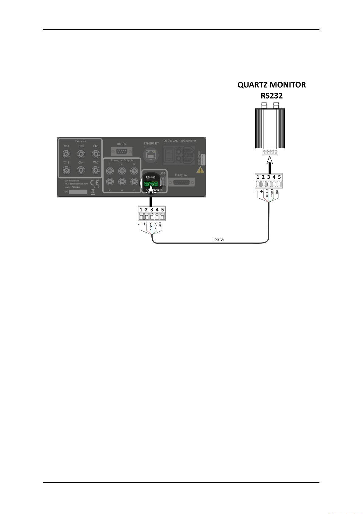
3.4.5.1 EXTERNAL RS232 MODULE
Only one QMB6 module can be connected with the RS232 interface. Example wiring diagram
see picture 3.6.
Figure 3.6: External QMB6 module - RS232
www.beamtec.de ; e-mail: [email protected] tel.: +49 731 146620 0
Wolfgang-Paul-Str. 4, 89081 Ulm, Germany
BeamTec
Page 25
25 TFM260 Thin Film Monitor
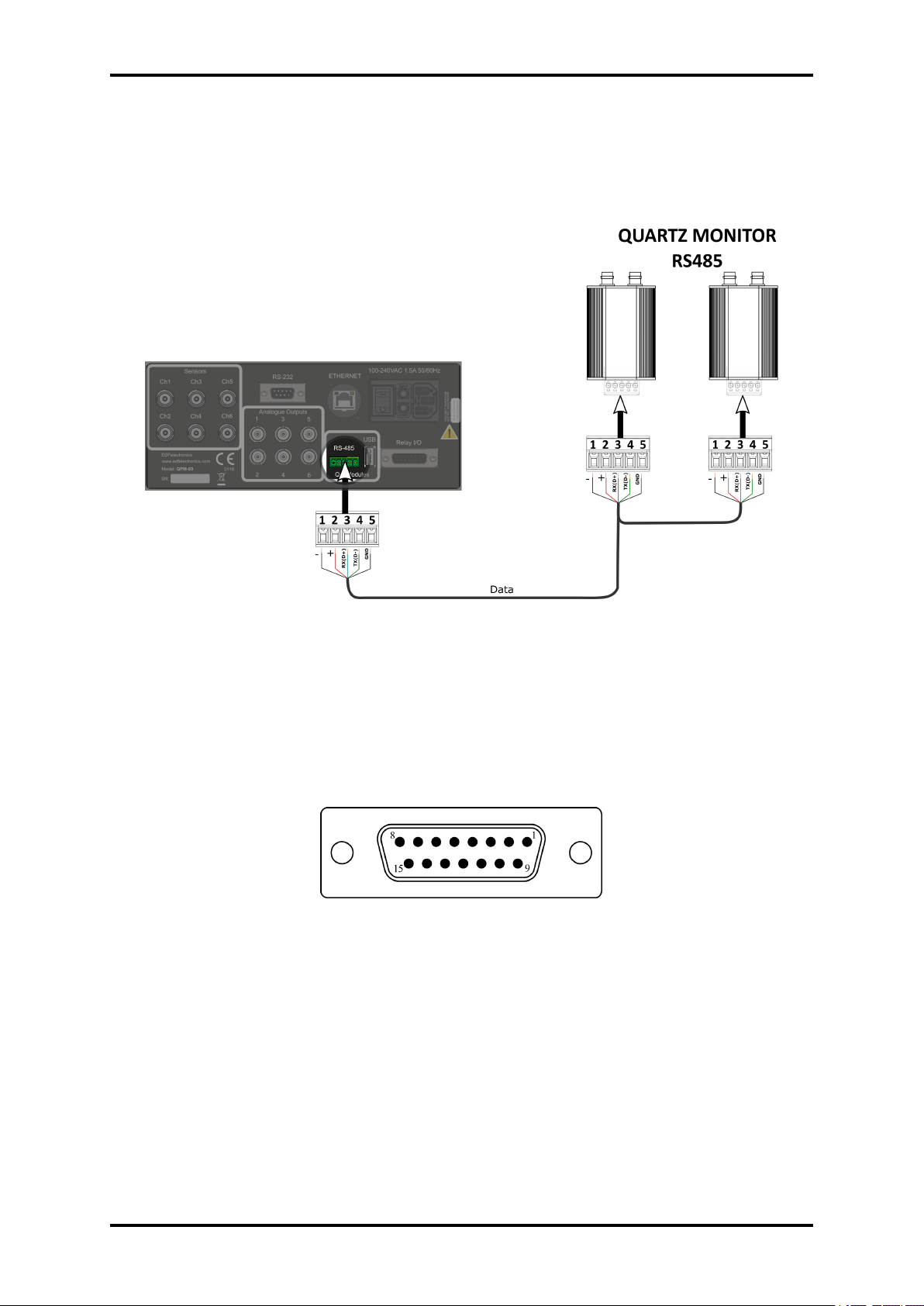
3.4.5.2 EXTERNAL RS485 MODULE
Up to 3 QMB6 module can be connected with the RS485 interface. Maximum module count
depends on hardware configuration. The modules are connected in parallel. Example wiring
diagram see picture 3.7.
Figure 3.7: External QMB6 module - RS485
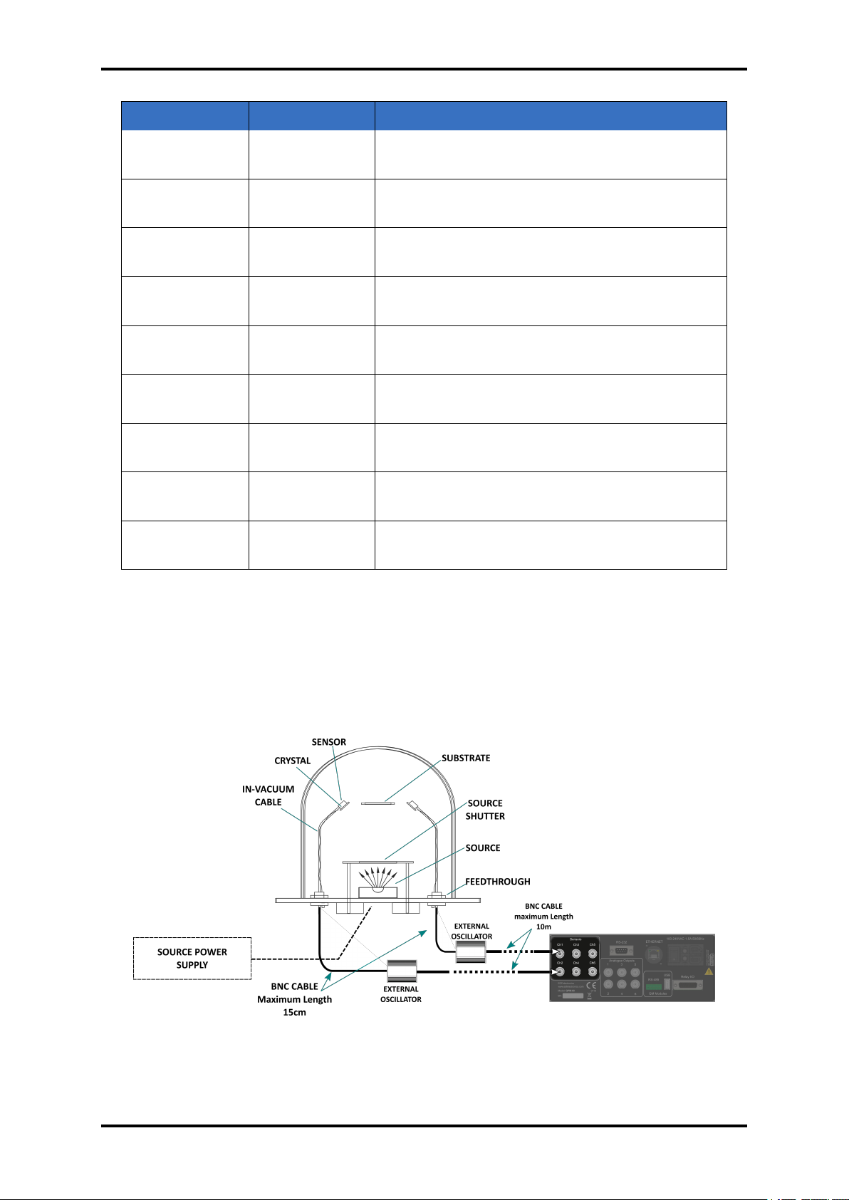
3.4.6 Relay I/O [7]
Connects 4 relays and 4 digital inputs to external devices. Each of the inputs and outputs can
be assigned one of several functions. Is configurable in setup menu, see section 4.3.8.
Figure 3.8: RS232 connector (D-sub male 15 pin )
www.beamtec.de ; e-mail: [email protected] tel.: +49 731 146620 0
Wolfgang-Paul-Str. 4, 89081 Ulm, Germany
BeamTec
Page 26
TFM260 Thin Film Monitor 26
PIN NUMBER FUNCTION DESCRIPTION
Pins 1,2 Relay 1 Normal open contact, activating dependent on
user setting
Pins 3,4 Relay 2 Normal open contact, activating dependent on
user setting
Pins 5,6 Relay 3 Normal open contact, activating dependent on
user setting
Pins 7,8 Relay 4 Normal open contact, activating dependent on
user setting
Pin 9 Input 1 Digital input pin, active low, action dependent on
user settings
Pin 10 Input 2 Digital input pin, active low, action dependent on
user settings
Pin 11 Input 3 Digital input pin, active low, action dependent on
user settings
Pin 12 Input 4 Digital input pin, active low, action dependent on
user settings
Pins 13, 14,
Ground
15
Table 3.4: Relay I/O - Pin functions and descriptions
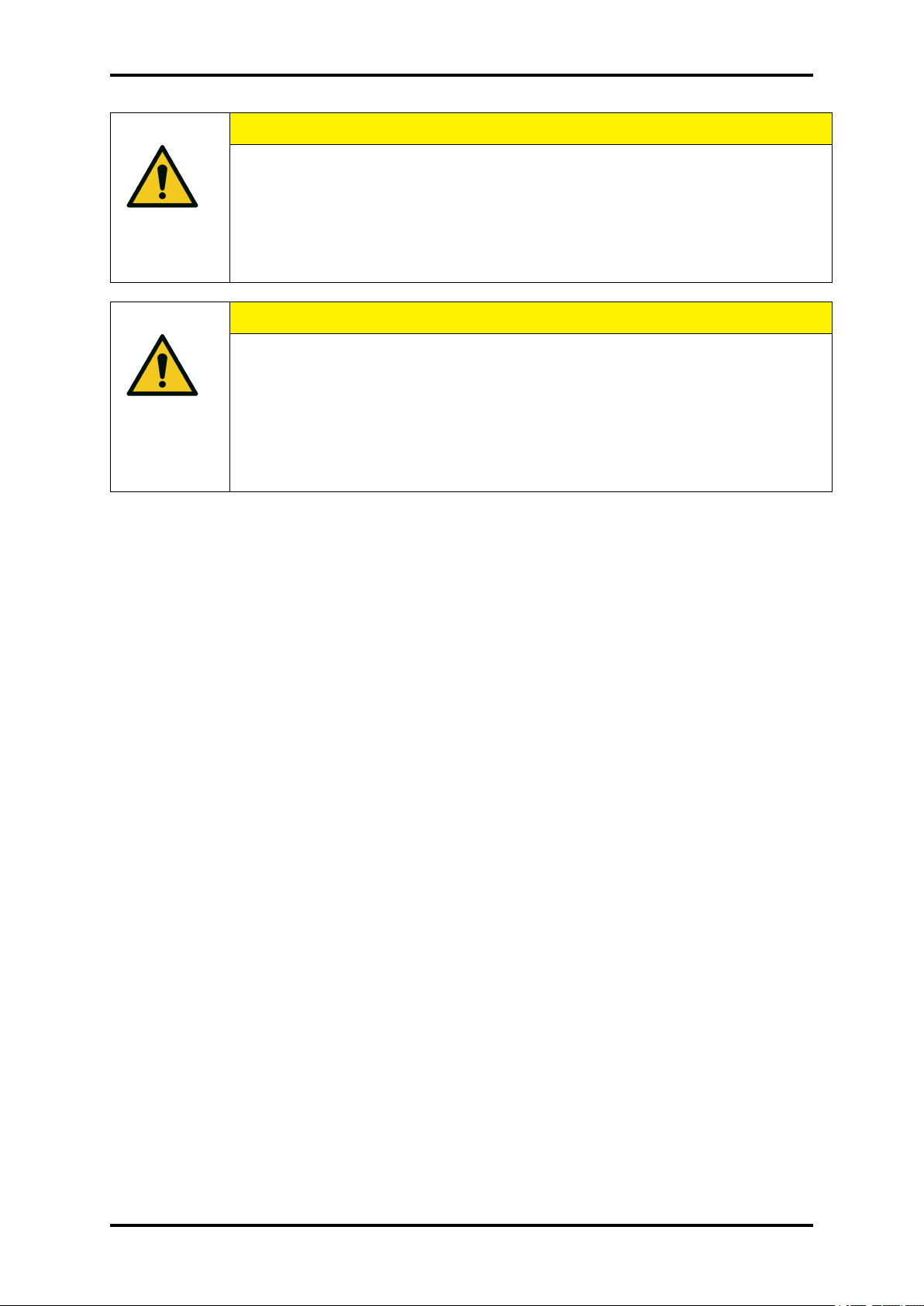
3.5 SYSTEM CONNECTIONS
A maximum of 6 sensors can be connected to the device (depending on the device’s hardware
version).
Figure 3.9: System connection - example diagram
www.beamtec.de ; e-mail: [email protected] tel.: +49 731 146620 0
Wolfgang-Paul-Str. 4, 89081 Ulm, Germany
BeamTec
Page 27
27 TFM260 Thin Film Monitor
CAUTION
The inputs are not isolated.
The inputs are not isolated. The voltage level applied must be limited between
0 and +5 V (dc), with respect to ground.
CAUTION
Output relays
Output relays are rated for 30 V (rms) or 30 V (dc), at 2 A maximum. Provide
proper fusing and adequate wiring insulation and separation in case the limits
are exceeded.
• Sensor
Holds the quartz crystal used to measure rate and thickness. Crystals must routinely be
replaced. Refer to the appropriate sensor operating manual for installation and maintenance instructions particular to that sensor.
• In-Vacuum Cable
Connects the sensor to the feedthrough.
• Feedthrough
Provides isolation between vacuum and atmosphere for electrical connections, water, air,
and/or purge gas tubes.
• BNC Cable - 15cm
Provides a flexible connection from the feedthrough to the oscillator.
• Oscillator
Contains the electronics to operate the quartz crystal. The length from the oscillator to the
crystal should be under 10 m.
• BNC Cable - 3m
Connects the oscillator to TFM260 . Lengths up to 10m are acceptable.
An external oscillator QMB6-EO need be used for each channel separately.
Connecting to the TFM260 :
1. Connect one end of the oscillator cable(coaxial cable) to selected TFM260 sensor connector.
www.beamtec.de ; e-mail: [email protected] tel.: +49 731 146620 0
Wolfgang-Paul-Str. 4, 89081 Ulm, Germany
BeamTec
Page 28
TFM260 Thin Film Monitor 28
WARNING
Maintain adequate insulation and physical separation of sensor and I/O wiring
from hazardous voltages.
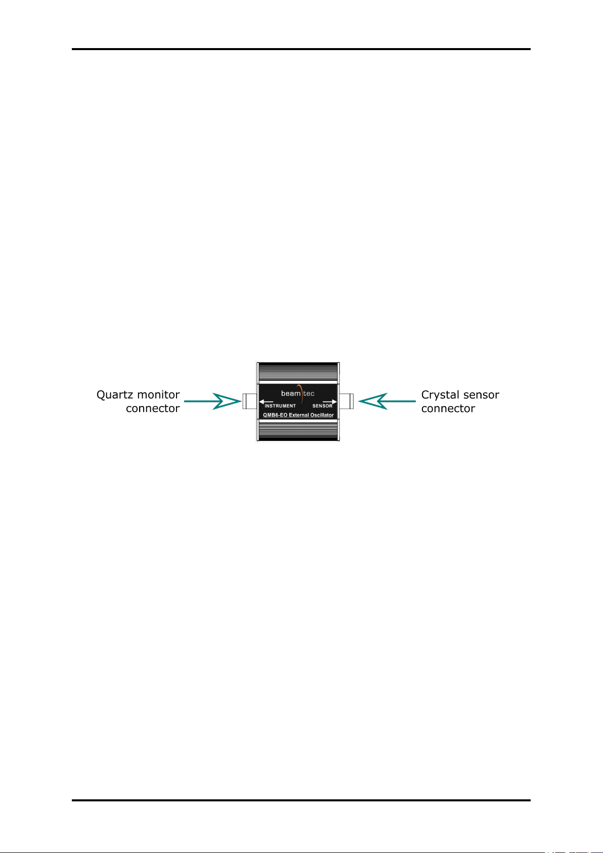
2. Connect the other end of the oscillator cable(coaxial cable) to BNC connector on the external oscillator(QMB6-EO ) labelled INSTRUMENT
3. Connect one end of the 15cm BNC cable to the BNC connector on the external oscillator(QMB6EO ) labelled SENSOR.
4. Connect the other end of the 15cm BNC cable to the BNC connector on the feedthrough
CAUTION
Proper TFM260 performance
• To maintain proper TFM260 performance, use only the provided 15 cm
BNC cable to connect TFM260 or the oscillator to the crystal sensor.
The length of the in-vacuum cable (Front Load and Sputtering sensors)
or electrical conduit tube (Cool Drawer and Bakeable sensors) must not
exceed 75cm.
• The maximum BNC cable length between external oscillator TFM260
-EO and TFM260 is 10m.
3.6 EXTERNAL OSCILLATOR
An external oscillator QMB6-EO need be used for each internal channel separately.
In order to connect QMB6-EO to the TFM260 :
1. Connect one end of the oscillator cable(coaxial cable) to selected TFM260 sensor connector.
2. Connect the other end of the oscillator cable(coaxial cable) to BNC connector on the external oscillator(QMB6-EO ) labelled INSTRUMENT
3. Connect one end of the 10cm BNC cable to the BNC connector on the external oscillator(QMB6EO ) labelled SENSOR.
4. Connect the other end of the 10cm BNC cable to the BNC connector on the feedthrough,
www.beamtec.de ; e-mail: [email protected] tel.: +49 731 146620 0
Wolfgang-Paul-Str. 4, 89081 Ulm, Germany
BeamTec
Page 29
29 TFM260 Thin Film Monitor
Figure 3.10: QMB6-EO connectors
www.beamtec.de ; e-mail: [email protected] tel.: +49 731 146620 0
Wolfgang-Paul-Str. 4, 89081 Ulm, Germany
BeamTec
Page 30
4 OPERATION
This chapter details the operation of the TFM260 menus and front panel controls.
4.1 EDIT VALUES
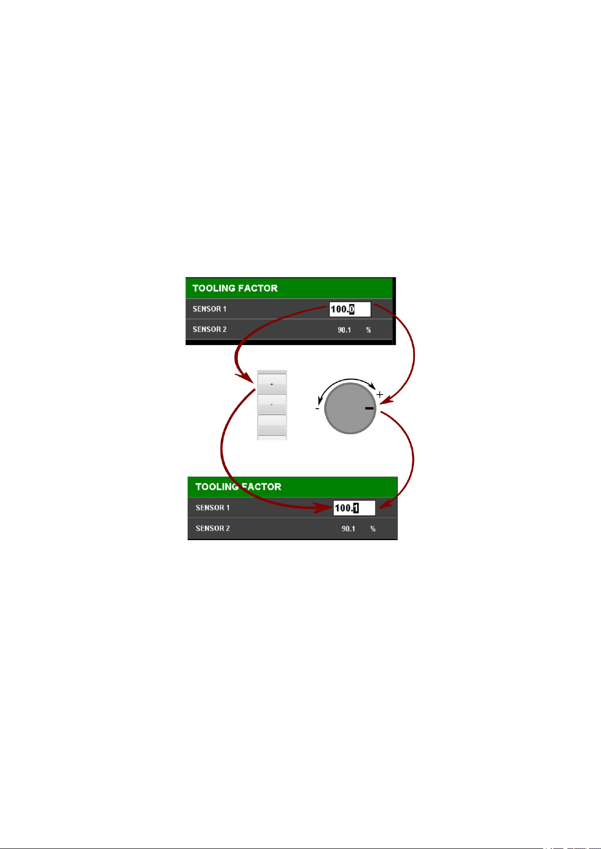
Editing the values that appear on the screen when using the device is done using the knob or
buttons on the left side of the screen. Editing the value by turning the knob: turning to the right
increases the edited value, while to the left it decreases. Editing the value using the buttons:
By means of the ”+” and ”-” buttons, the edited value is increased and decreased accordingly.
Figure 4.1: Edit Values
4.2 MAIN SCREEN
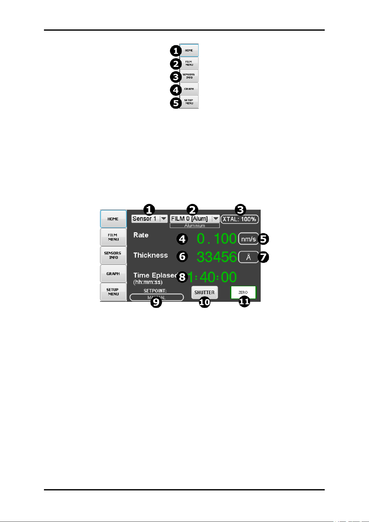
On the left side of the screen there are buttons for selecting individual views available in the
device:
1. HOME - display Home Window with main sensor parameters.
2. FILM MENU - displays the configuration window of individual films defined in the device.
3. SENSORS INFO - summarized in Table displays detailed information on the current status
of measuring inputs.
30
Page 31
31 TFM260 Thin Film Monitor
Figure 4.2: Main Screen Buttons
4. GRAPH - draws a graph based on the parameters defined in Setup Menu.
5. SETUP MENU - opens a menu with options enabling advanced configuration of device
operation parameters, input and output settings, etc.
4.2.1 HOME WINDOW
Figure 4.3: TFM260 Home Screen
1. Sensor select list - selection of the sensor. all parameters below are directly related to the
sensor selected from the list.
2. Film select list - assigning selected film to the selected sensor. In order to modify the
settings of a given module, go to the FILM MENU, see section 4.5.
3. Crystal life indicator - show crystal life status for selected sensor. The indications depend on the settings in the menu 4.3.5. Pressing this field displays the Crystal Min/Max
configuration menu.
4. Rate value - show current rate value for selected sensor
5. Rate unit - Pressing this field displays unit change list see figure 4.4
6. Thickness value - show current thickness value for selected sensor,
7. Thickness unit - Pressing this field displays unit change list see figure 4.4
www.beamtec.de ; e-mail: [email protected] tel.: +49 731 146620 0
Wolfgang-Paul-Str. 4, 89081 Ulm, Germany
BeamTec
Page 32
TFM260 Thin Film Monitor 32
8. Time value - show current time value, when shutter is opened then value is increment, for
selected sensor
9. Setpoint mode - indicate current setpoint mode for select film. Pressing this field displays
the FILM MENU.
10. Shutter button pressing button open shutter(if configured) and reset Time
11. Zero button - pressing button reset thickness value for selected sensor
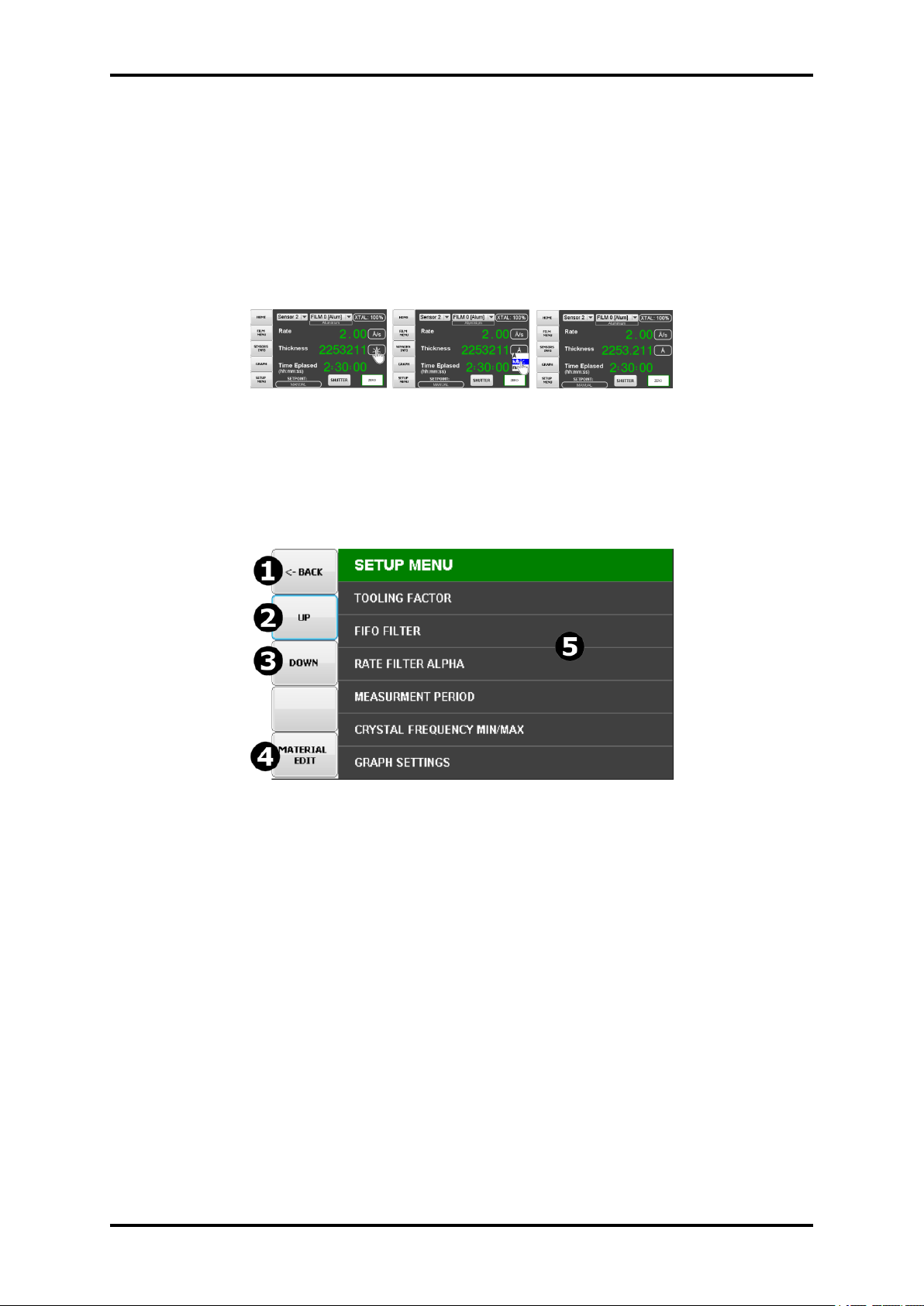
Figure 4.4: Unit change example screen
4.3 SETUP MENU
Figure 4.5: Setup menu
1. ”Go Back” button - Depending on the menu level you are currently in, it causes various
actions: return to the level menu above or return to the main screen.
2. ”UP” button - move swipe list Up
3. ”DOWN” button - move swipe list Down
4. ”MATERIAL EDIT” - displays the material editing menu
5. Items list - selecting and pressing the item will take you to the next menu level,
4.3.1 SENSOR TOOLING FACTOR
Sensor Tooling adjusts for the difference in deposition rate between the sensor and the substrate
being coated. It is an empirically determined value that aligns the sensor readings to the vacuum
system.
www.beamtec.de ; e-mail: [email protected] tel.: +49 731 146620 0
Wolfgang-Paul-Str. 4, 89081 Ulm, Germany
BeamTec
Page 33

33 TFM260 Thin Film Monitor
Figure 4.6: Toolng Factor submenu
1. Sensor Item,
2. Tooling factor value for sensor,
• 100% tooling indicates that the sensor and substrate receive the same amount of material
during deposition.
• Tooling values over 100% indicate that the sensor receives less materialthan the substrate
(see section 8.1).
• Tooling values under 100% indicate that the sensor receives more material than the substrate (see section 8.1).
Tooling is set in the System menu. It adjusts the tooling for each individual sensor before it is
averaged. Sensor Tooling for a sensor applies to all films. If the Sensor Tooling parameters are
set properly, a sensor failure will not cause a jump in the average Rate and Thickness reading.
The value can be set in the range from 10% to 400% Also check: ”Film Tooling Factor” section
4.5.
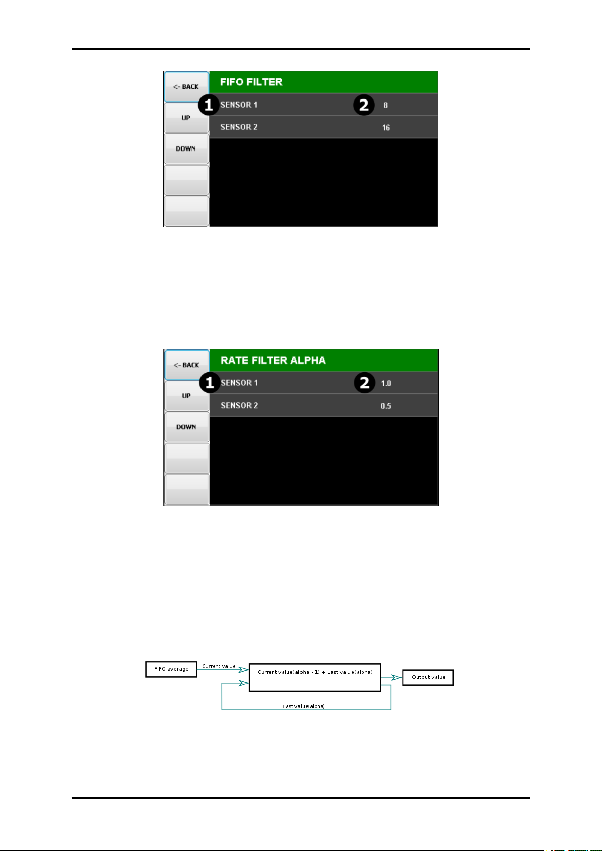
4.3.2 FIFO FILTER
The number of readings averaged for the frequency, thickness and rate display. Values of 1 to
63 are valid. A value of 0 indicates no averaging. The parameter value is set for each channel
separately.
1. Sensor Item,
2. Fifo Filter value for sensor,
NOTE: The number of readings averaged per second is dependent on the Measurement period
settings see 4.3.4.
www.beamtec.de ; e-mail: [email protected] tel.: +49 731 146620 0
Wolfgang-Paul-Str. 4, 89081 Ulm, Germany
BeamTec
Page 34
TFM260 Thin Film Monitor 34
Figure 4.7: FIFO filter submenu
4.3.3 RATE FILTER ALPHA
Selects the amount of filtering used to display rate data. An Alpha of 1 is no filtering. An Alpha
of 0.1 is heavy filtering. The parameter value is set for each channel separately.
Figure 4.8: Alpha filter submenu
1. Sensor Item,
2. Alpha Filter value for sensor,
NOTE: Low alpha values give a very stable display, but will lag actual rate readings and can
hide noise problems.
Figure 4.9: Alpha filtering diagram
www.beamtec.de ; e-mail: [email protected] tel.: +49 731 146620 0
Wolfgang-Paul-Str. 4, 89081 Ulm, Germany
BeamTec
Page 35
35 TFM260 Thin Film Monitor
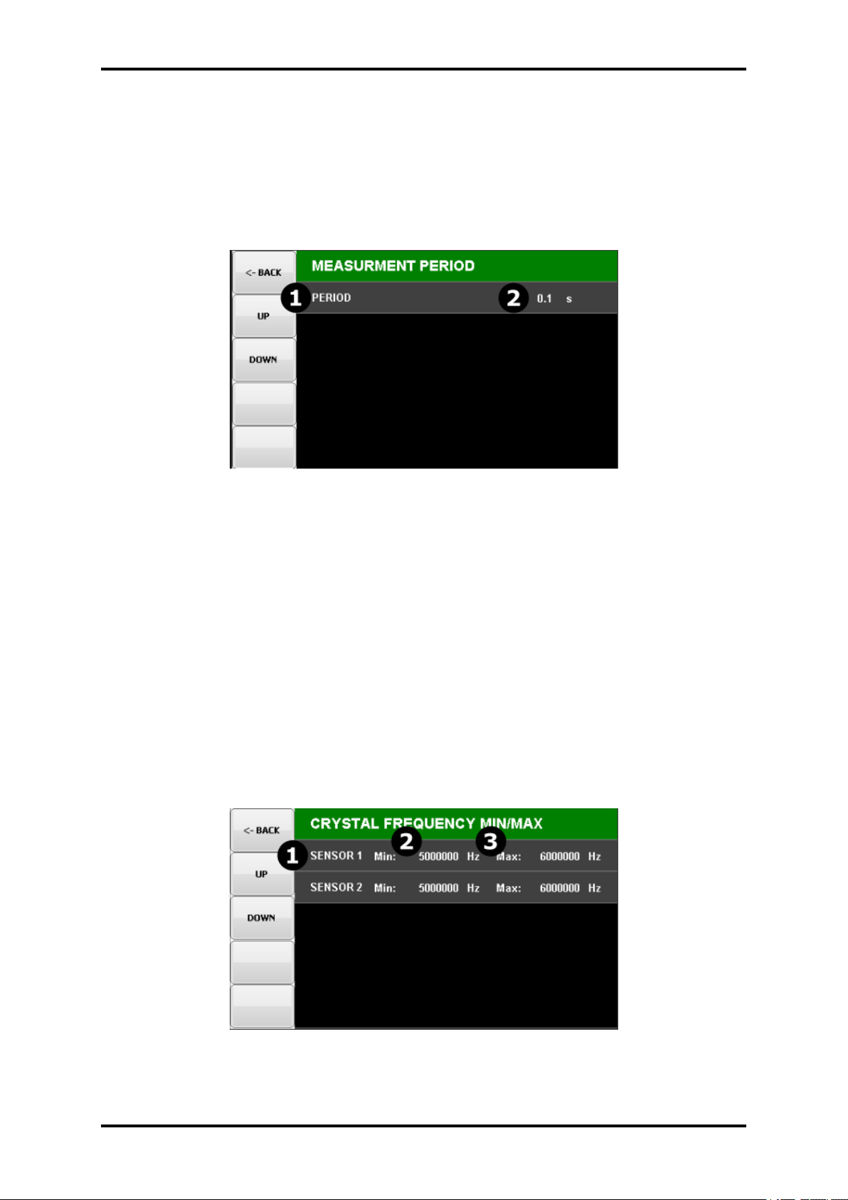
4.3.4 MEASURMENT PERIOD
Sets the measurement interval between 0.1 second (10 readings per second) and 2 second.
The parameter value is common to all internal measurement channels.
For external channels(if available), the value can be set individually. A longer period gives
higher reading accuracy, especially in low rate and low density applications. Time required for
a measurement. Longer times yield higher accuracy.
Figure 4.10: Measurment peroid submenu
1. Sensor Item,
2. Measurement period for internal channels,
3. (*) Measurement period for connected external modules,
4.3.5 CRYSTAL FREQUENCY MIN/MAX
Sensor Minimum and Maximum frequencies establish the operating range for the sensing quartz
crystals. Both values are used to determine the % life that is displayed in Xtal Life mode. When
the sensor frequency reads below the minimum or above the maximum, TFM260 indicates a
sensor failure (crystal fail) with a red color Crystal Status indicator.
Figure 4.11: Crystal Min/Max submenu
www.beamtec.de ; e-mail: [email protected] tel.: +49 731 146620 0
Wolfgang-Paul-Str. 4, 89081 Ulm, Germany
BeamTec
Page 36
TFM260 Thin Film Monitor 36
Figure 4.11 description:
1. Sensor Item,
2. Crystal frequency minimum, if the value is smaller then the device displays the status
”XTAL FAIL”,
3. Crystal frequency maxiumum, if the value is bigger then the device displays the status
”XTAL FAIL”
Crystals sometimes fail unexpectedly, or exhibit erratic frequency shifts (mode hopping) before
total failure. Depending on the material, crystals may fail well before the typical 5 MHz minimum.
If the crystals consistently fail early, set FREQ MIN to a value higher than 5 MHz to provide a
Crystal Life warning that is consistent with actual failure. A sensor crystal with an initial value
that exceeds the maximum frequency will also cause a flashing Crystal Status indicator. The
maximum frequency can be set slightly above the nominal values with no effect on accuracy.
TFM260 calculates the crystal life value based on the currentfrequency compared to the 𝐹
/𝐹
values set in the System menu. A new crystal should indicate between 95 and 100% crystal
life.
CAUTION
Crystal life status
Usable crystal life depends on the material being evaporated and other process characteristics. Rate noise and other failure modes may be observed
before the crystal life value reaches 0%.
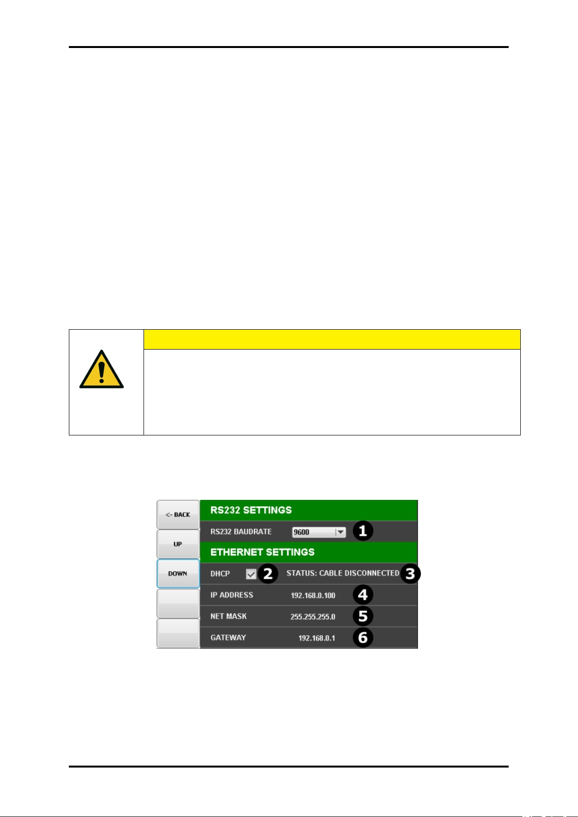
4.3.6 COMMUNICATIONS
Figure 4.12: Serial interface and Ethernet parameters
1. Baudrate select list
2. DHCP checkbox - if checked then DHCP is enabled
www.beamtec.de ; e-mail: [email protected] tel.: +49 731 146620 0
Wolfgang-Paul-Str. 4, 89081 Ulm, Germany
BeamTec
Page 37

37 TFM260 Thin Film Monitor
3. Cable status - display information about ethernet cable, in order to easily diagnose basic
connection problems.
• Cable disconnected - when cable is not plug to the RJ45 socket
• Cable connected - when cable is plug correctly and TFM260 communicates correctly
with another network device (router, switch, computer)
4. Internet protocol address - the value is editable when DHCP is disabled, otherwise the
value is greyed out and can not be edited.
5. Net mask - the value is editable when DHCP is disabled, otherwise the value is greyed
out and can not be edited.
6. Gateway address - the value is editable when DHCP is disabled, otherwise the value is
greyed out and can not be edited.
4.3.6.1 RS232
RS-232 serial communications are accomplished through an industry standard 9-pin female
connector found on the TFM260 rear panel (refer to 3.4.2). A mating male connector is required
to attach a host interface. The host and TFM260 can be separated by up to 15 m using a
multiconductor shielded data cable. For successful communications, the baud rate of the host
computer and TFM260 must match. Available baud rate options are: 19200, 38400, 57600, and
115200 bps. NOTE: Unpredictable RS-232 hardware/software combinations may occasionally
cause a command to not be recognized by TFM260 . Consequently, all communications should
include an automatic retry procedure. If a command sent using RS-232 does not produce a
response from TFM260 within three seconds, it should be sent again.
4.3.6.2 Ethernet
For Ethernet communications, TFM260 uses the static Internet Protocol (IP) (default address
192.168.0.100) The optional TCP/IP interface supports only the Standard Ethernet TCP/IP protocol. TFM260 will communicate using TCP/IP on TCP port number 2101.
DHCP is also supported.
4.3.7 ANALOGUE OUTPUTS
TFM260 features analog outputs that will produce a 0 to 10 V (dc) representative of the current
rate, thickness or frequency. Analogue outputs connectors are available on rear panel see section 3.4.4 You can assign any type of signal from any sensor to any analogue output. It is also
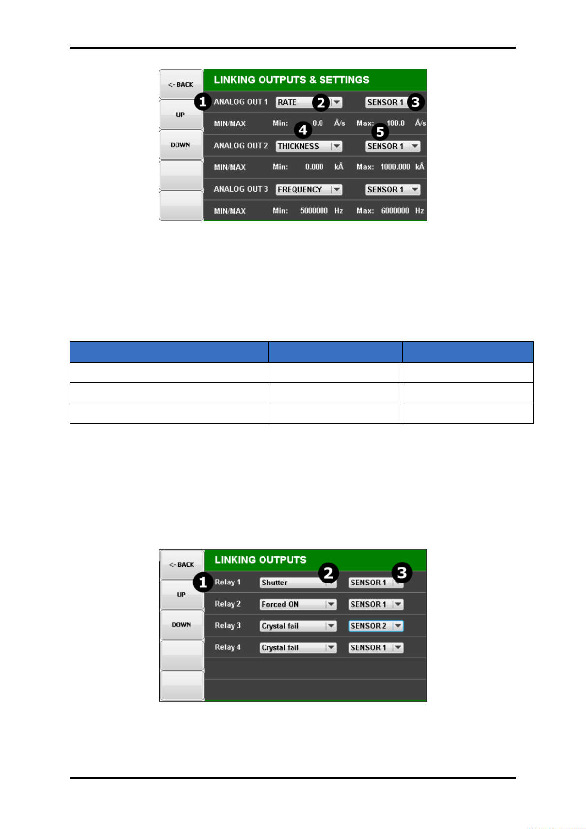
possible to assign the same signal several times to several analogue outputs.
1. Analogue output Item,
2. Parameter selection list
3. Sensor selection list
4. Minimum value for selected parameter - corresponds with 0V on analogue output
www.beamtec.de ; e-mail: [email protected] tel.: +49 731 146620 0
Wolfgang-Paul-Str. 4, 89081 Ulm, Germany
BeamTec
Page 38
TFM260 Thin Film Monitor 38
Figure 4.13: Analogue Outputs Submenu
5. Maxiumum value for selected parameter - corresponds with 10V on analogue output
Analogue outputs must be set to match the device that will be attached to the Rate, Thickness or
Frequency output. The value of the analogue output is constantly updated 10 times per second.
PARAMETER MIN VALUE MAX VALUE
Frequency 4500000Hz 6500000Hz
Rate -100 A/s 100 A/s
Thickness 0 9999kA
Table 4.1: Analogue outputs functions
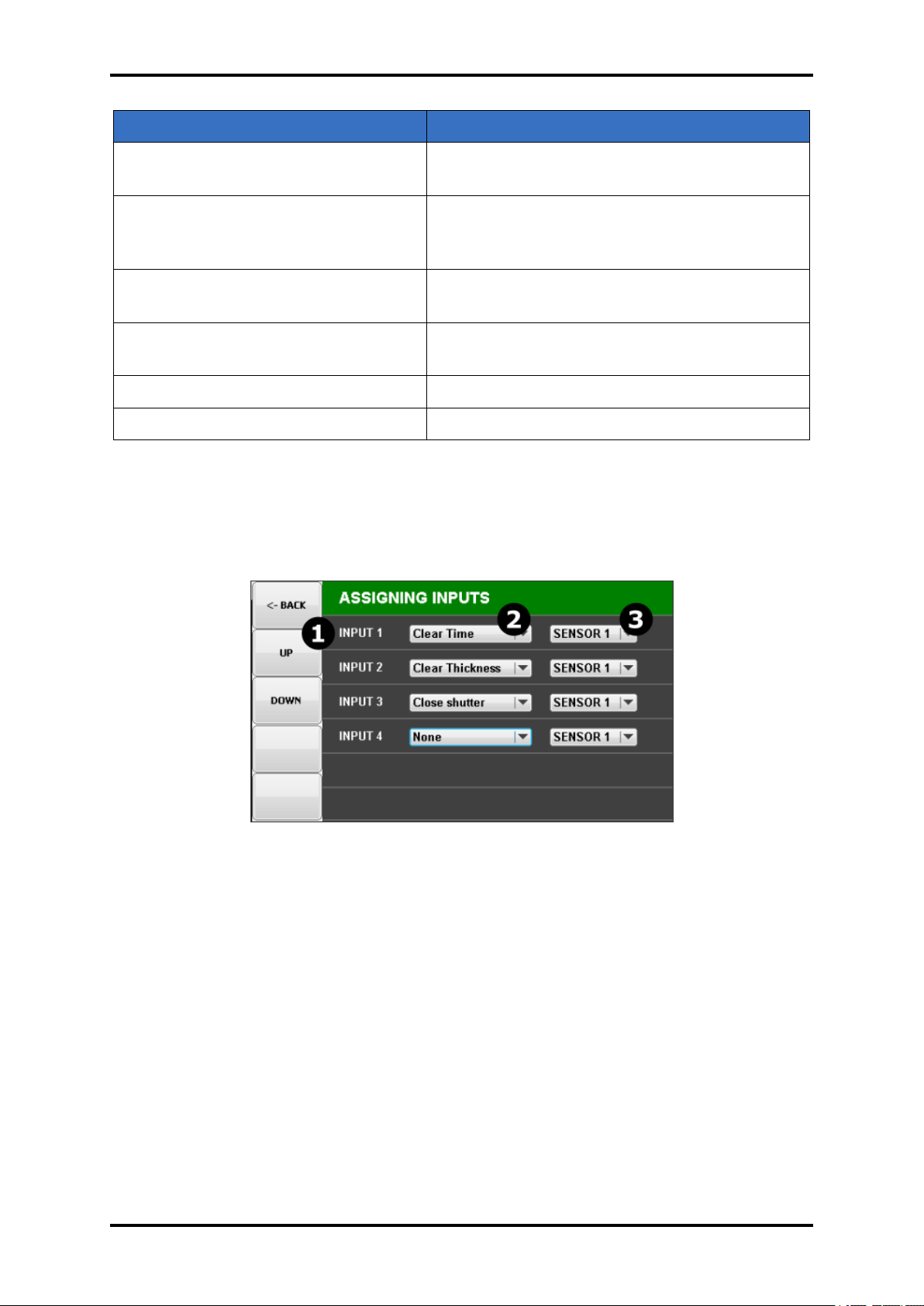
4.3.8 RELAY OUTPUTS
The Relay outputs menus of the System Parameters menu allow the operator to display and
edit relays function. Allows to assign relay functions to physical relay output.
Figure 4.14: Relay Outputs Submenu
www.beamtec.de ; e-mail: [email protected] tel.: +49 731 146620 0
Wolfgang-Paul-Str. 4, 89081 Ulm, Germany
BeamTec
Page 39
39 TFM260 Thin Film Monitor
PARAMETER VALUE
Thickness setpoint Relay is activate when thickness value reached
setpoint
Crystal Failure Relay is activate when the sensor frequency
reads below the minimum or above the maximum
Shutter Relay is connected with button on main screen,
and is activated when button is pressed
Dual sensor Relay is connected with button on main screen,
and is activated when button is
Forced ON Selected relay is switched ON permanently
Forced OFF Selected relay is switched OFF permanently
Table 4.2: Relay outputs function
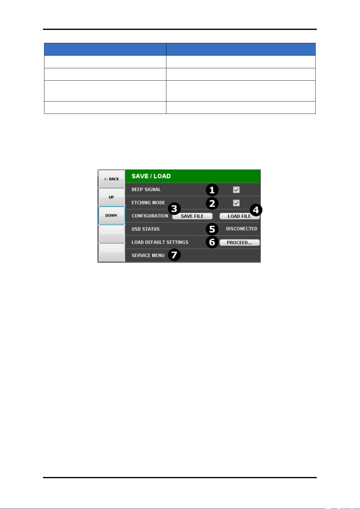
4.3.9 ASSIGNING INPUTS
The options allow you to configure the behavior of the device in relation to the input signals.
Figure 4.15: Digital Inputs Submenu
www.beamtec.de ; e-mail: [email protected] tel.: +49 731 146620 0
Wolfgang-Paul-Str. 4, 89081 Ulm, Germany
BeamTec
Page 40
TFM260 Thin Film Monitor 40
PARAMETER VALUE
Zero Time The time of the assigned sensor is reset
Zero Thickness The thickness of the assigned sensor is reset
Open/Close shutter The shutter open/close signal is provided to as-
signed sensor
None input inactive
Table 4.3: Digital inputs function
4.3.10 ADVANCED SETTINGS
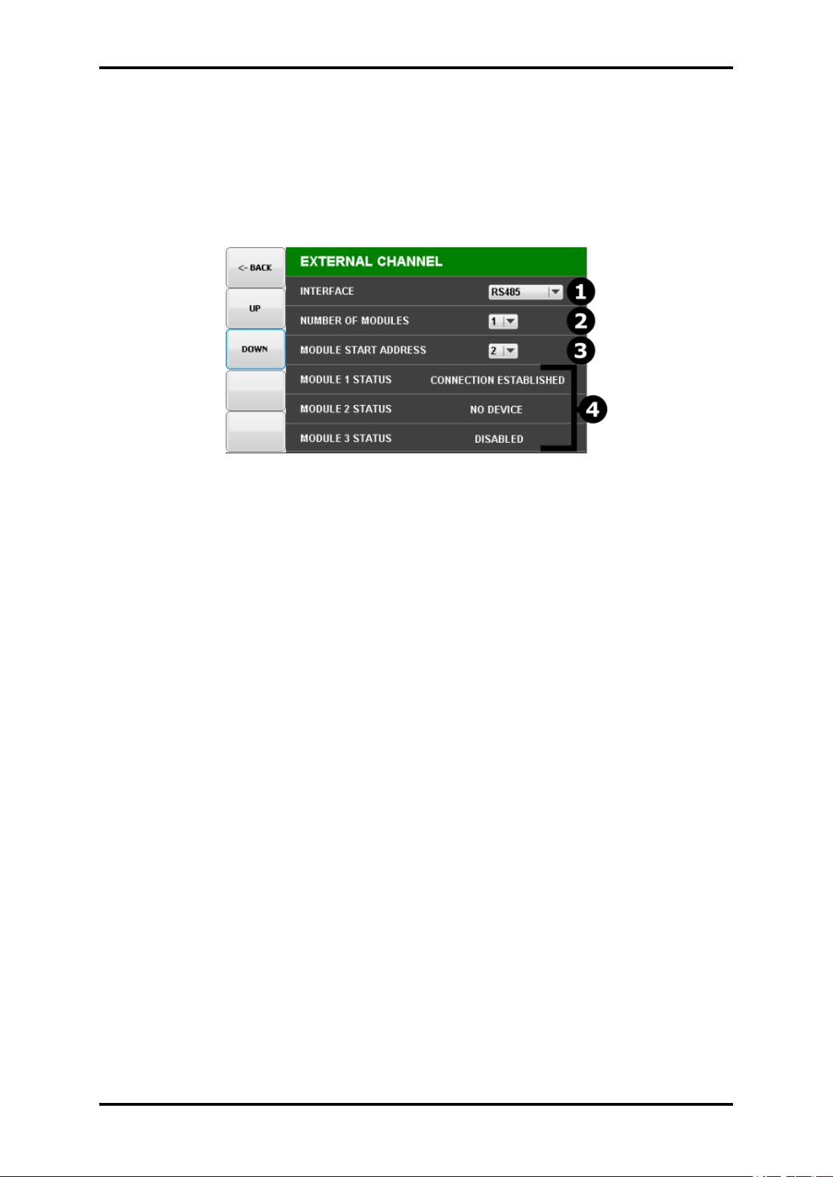
The options available in this submenu allow advanced configuration of device parameters.
Figure 4.16: Configuration Submenu
1. BEEP SIGNAL - turns on / off the sound signal when using the device
2. ETCHING MODE - Sets the rate and thickness to negative values for etching applications.
3. CONFIGURATION - Allows you to save / load the device configuration. To do this, connect
a USB stick to the device and select the:
• ”SAVE FILE” for export device configuration to USB stick,
• ”LOAD FILE” for load device configuration from USB stick,
Configuration is save as a text file that can be previewed and edited using any text editor.
4. USB STATUS - display current USB status:
• DISCONECTED - usb media not connected to the device or not recognized correctly,
• CONNECTED - usb carrier correctly recognized and ready to read / write,
5. LOAD DEFAULT SETTINGS - Set all device parameters to default
• Setup menu settings,
• Material menu parameters(Remove user define parameters),
www.beamtec.de ; e-mail: [email protected] tel.: +49 731 146620 0
Wolfgang-Paul-Str. 4, 89081 Ulm, Germany
BeamTec
Page 41
41 TFM260 Thin Film Monitor
• Film menu settings(all films are set to default parameters),
6. SERVICE MENU - Menu available only for the device manufacturer, is used for calibration
and testing of the device at the production stage.
4.3.11 EXTERNAL CHANNEL
Figure 4.17: External channel configuration Submenu
External channel submenu is used to configure the operating parameters with the external measuring module. Default, the support of external modules is disabled: parameter Number of mod-
ules is set to 0. Selecting from the list a value other than 0 activates the operation of external
modules. The module is visible in the device as two consecutive measurement channels, with
the extension ”ext” added, example main screen and setup menu see pictures 4.18, 4.19.
www.beamtec.de ; e-mail: [email protected] tel.: +49 731 146620 0
Wolfgang-Paul-Str. 4, 89081 Ulm, Germany
BeamTec
Page 42
TFM260 Thin Film Monitor 42
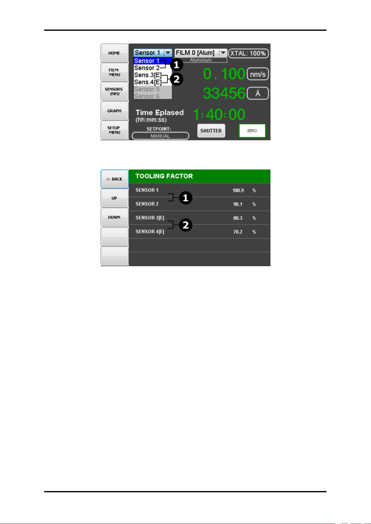
Figure 4.18: External channels avalible on Sensor List
Figure 4.19: External channels avalible on Setup menu(example)
1. Interface type of the included QM module, available options:
• RS232
• RS485
2. The number of modules connected to the device, for the RS232 interface, the option is
not active and always equal to 1. For RS485, up to three modules can be selected.
3. This option is used when connecting a module with an RS485 interface. It allows you to
choose the address under which you should look for the first module. For example, for
two connected modules and the starting address 5, the device assumes that the second
module has the address 6.
4. Module status items, return information about current status of connected external modules
• ”CONNECTION ESTABLISHED” - the external module is connected and the communication has been correctly established,
• ”NO DEVICE” - module is enabled for communication but is not connected
• ”DISABLED” - module disabled for communication,
www.beamtec.de ; e-mail: [email protected] tel.: +49 731 146620 0
Wolfgang-Paul-Str. 4, 89081 Ulm, Germany
BeamTec
Page 43
43 TFM260 Thin Film Monitor
4.3.12 INFORMATION
Contains information about the software version on the device and the modules attached to it.
4.4 MATERIAL LIST
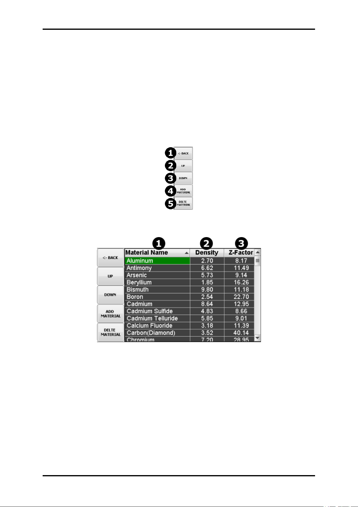
The device has factory defined over 80 materials and additionally allows you to define up to 10
of your materials. The list consists of three columns: material name, acoustic impedance value
and A Z-Factor value. The materials are displayed in alphabetical order. The material defined
by the user may have an individual name and parameters.
4.4.1 ADD MATERIAL
Figure 4.20: Material Menu Buttons
Figure 4.21: Material Menu
The material is added by pressing the ADD MATERIAL button. Default parameters for each
added material item.
• Name: UserDef(n),
• Acoustic Impedance: 1.00,
• Z-Factor: 1.00,
www.beamtec.de ; e-mail: [email protected] tel.: +49 731 146620 0
Wolfgang-Paul-Str. 4, 89081 Ulm, Germany
BeamTec
Page 44
TFM260 Thin Film Monitor 44
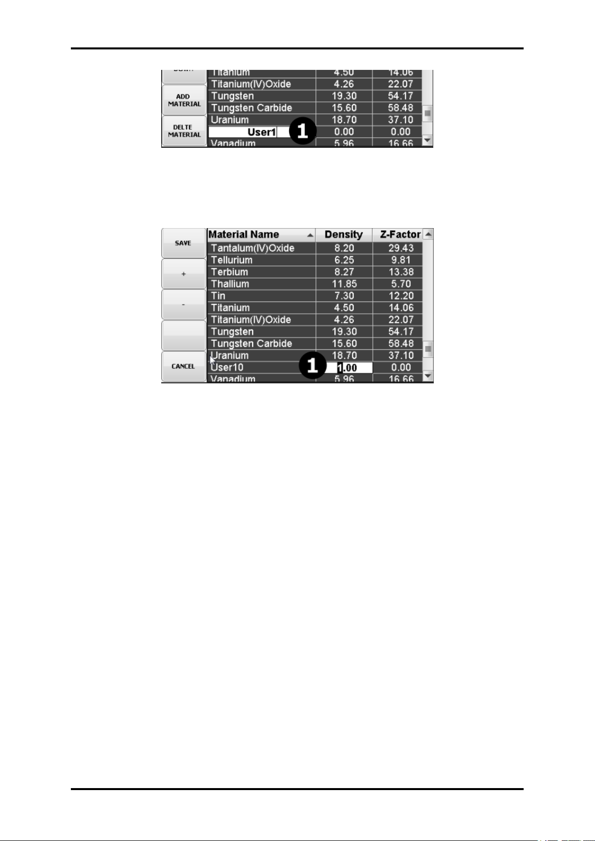
Figure 4.22: Add Material
4.4.2 EDIT MATERIAL
Figure 4.23: Edit Material
Acoustic Impedance value and Z-Factor value for all items on the material list can be modified by
the user. In addition, for material defined by the user, the name of the material can be modified
at any time. The modified material will appear in the material list in alphabetical order.
it is possible to restore the list of materials to the factory state (default values). To do this, use
the option ”Load default parameters”. See the section: 4.3.10
4.4.3 DELETE MATERIAL
if for any reason you want to delete the material, you can do it using the DELETE MATERIAL
button. It is possible to remove only those materials that we previously defined ourselves. It is
not possible to delete factory-defined materials.
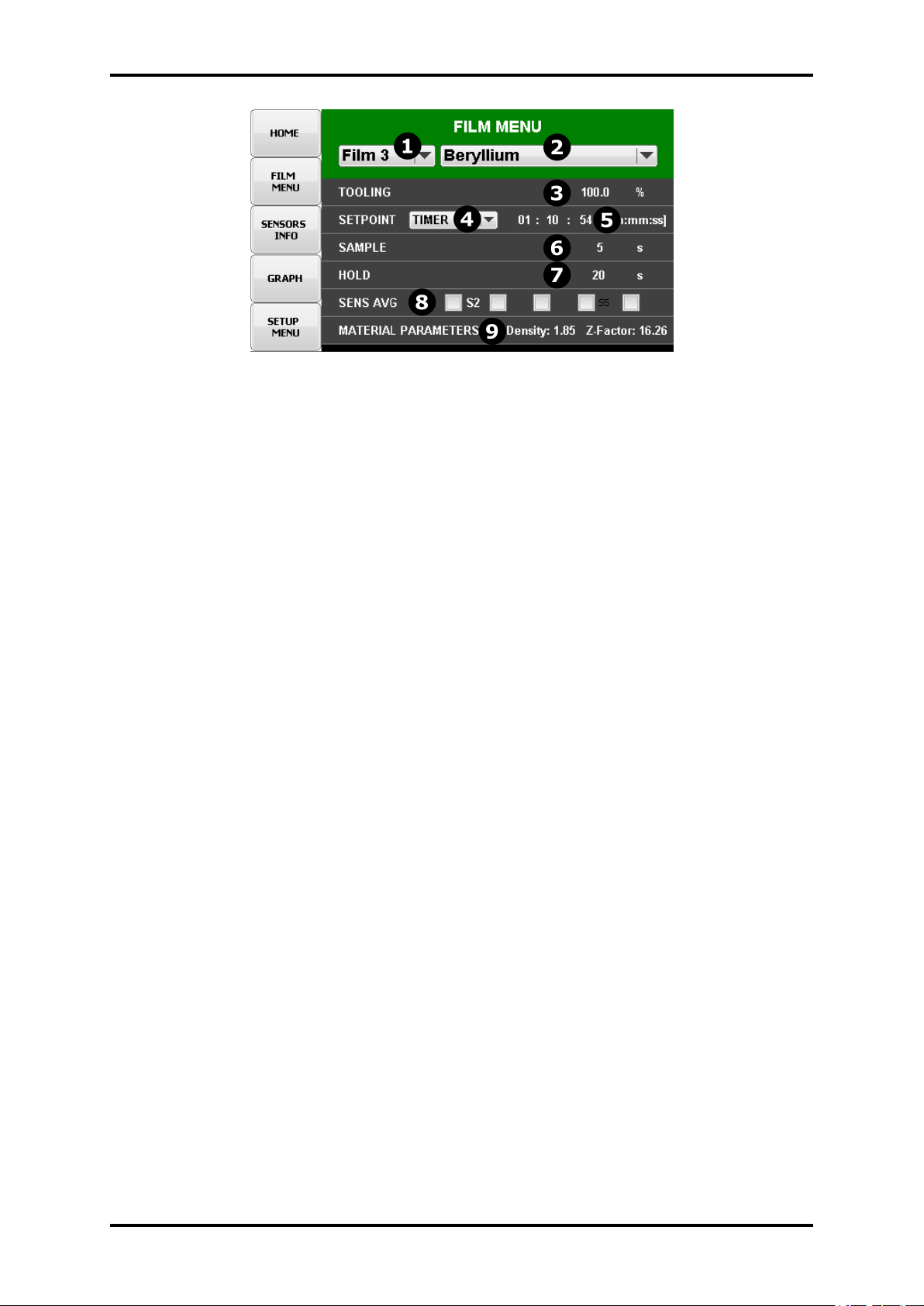
4.5 FILM MENU
The Film menu aids in programming TFM260 for the materials that will be deposited. Ninetynine films can be stored, but only one film for each sensor is active at any time.
1. Film select list - selection of film to edit
2. Material select list - assigning the selected material to the selected sensor. Material list
and edit material parameters see section 4.4
3. Setpoint selection:
www.beamtec.de ; e-mail: [email protected] tel.: +49 731 146620 0
Wolfgang-Paul-Str. 4, 89081 Ulm, Germany
BeamTec
Page 45
45 TFM260 Thin Film Monitor
Figure 4.24: Film menu
• Thickness - The desired final thickness of this layer. The deposition phase of this
layer will end when this thickness is reached.
• Time Setpoint - Sets a time, after shutter open, when the shutter is automatic closed.
• Manual - Allows manual shutter control
4. Film Tooling- Compensates for sensor sensitivity to the selected material. Use Crystal
Tooling in the System menu to compensate for each sensor individually.
5. Sensor 1-6 - Activates/Deactivates each quartz crystal sensor to be used for the selected
film. If multiple sensors are assigned to a film, their readings are averaged. If multiple
sensors are assigned to a film, and one fails, it is excluded from measurements. Sensors
3, 4, 5 and 6 will not be displayed unless the optional sensor board is installed in TFM260
.
6. Material Parameters:
Material: Selects a material assigned to this film. As materials change, their density and
Z-Ratio is updated. Density: Material density has a significant impact on deposition calculations.
Z-Factor: an empirically determined measure of the effect a material has on quartz crystal
frequency change. Common materials, densities, and Z-Ratios are listed in Appendix A.
4.5.1 RATE SAMPLING
Rate sampling can extend the life of crystals. With rate sampling, the deposition rate is sampled
for a period of time, then the sensor shutter is closed. Sample The time for the sensor shutter
to remain open when Sampling is enabled in the System menu. Not available when Sampling is
disabled in System menu. Hold The time for the sensor shutter to remain closed when Sampling
is enabled in the System menu. Not available when Sampling is disabled in System menu.
4.6 SENSOR INFO MENU
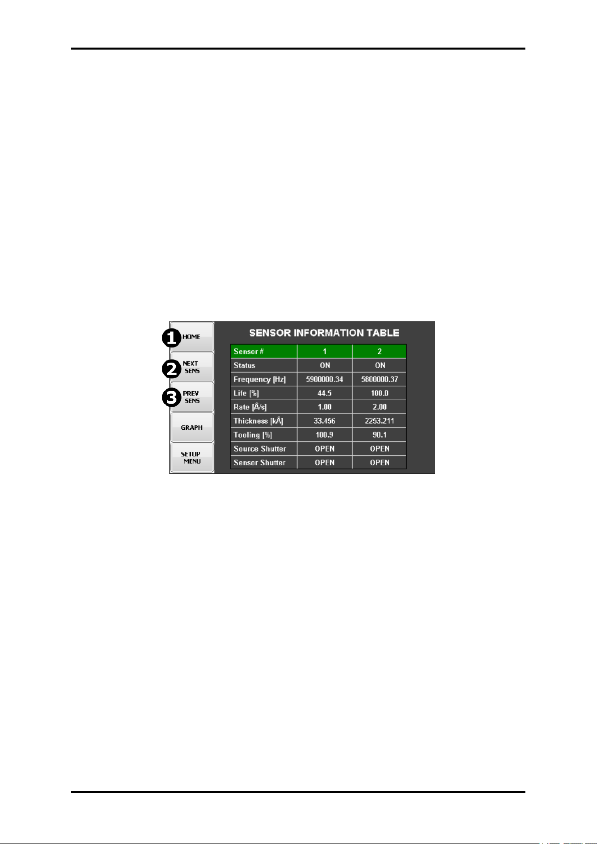
The screen combines information about the individual sensors attached to the device. The data
is constantly updated and refreshed. Between channels switch to using the buttons ”2” - ”NEXT
SENS” and ”3”- ”PREV SENS”.
www.beamtec.de ; e-mail: [email protected] tel.: +49 731 146620 0
Wolfgang-Paul-Str. 4, 89081 Ulm, Germany
BeamTec
Page 46
TFM260 Thin Film Monitor 46
Figure 4.25: Sensor Info
www.beamtec.de ; e-mail: [email protected] tel.: +49 731 146620 0
Wolfgang-Paul-Str. 4, 89081 Ulm, Germany
BeamTec
Page 47
5 OPERATION - REMOTE CONTROL
TFM260 offers the following types of data communications hardware ports.
• Serial RS-232 port
• Ethernet port
Both the host and server must have the same form of communications equipment and complementary setup. For serial communications, the baud rates and data word format must match.
The word format for bit serial lines (RS-232) is comprised of ten signal bits: eight data bits, one
start bit, one stop bit, and no parity. The eight data bits contain a byte of information or character
whose ASCII value ranges from 0 to 255.
5.1 RS232 COMMUNICATION
RS-232 serial communications are accomplished through an industry standard 9-pin female
connector found on the TFM260 rear panel (3.4.2). A mating male connector is required to
attach a host interface. The host and TFM260 can be separated by up to 15.2 m (50 ft.) using multiconductor shielded data cable. For successful communications, the baud rate of the
host and SQM-160 must match. Available baud rate options are: 2,400, 4,800, 9,600, 19,200,
38,400, 57,600, and 115,200 bps. TFM260 is configured as DCE (Data Communication Equipment).
CAUTION
Unpredictable RS-232
Unpredictable RS-232 hardware/software combinations may occasionally
cause a command to not be recognized by TFM260 . Consequently, all communications should include an automatic retry procedure. If a command sent
via RS-232 does not produce a response from TFM260 within three seconds,
it should be sent again.
5.2 ETHERNET PORT
For Ethernet communications, TFM260 uses the static IP address 192.168.1.200. The optional
Ethernet port supports only the Standard Ethernet TCP/IP protocol. TFM260 will communicate
using TCP/IP on TCP port number 2101. The interface supports static and DHCP addressing.
Ethernet parameters allow the IP address and the net mask to be set. A standard Ethernet
cable is required to connect TFM260 through a network or hub connection.
47
Page 48

TFM260 Thin Film Monitor 48
5.3 COMMUNICATIONS PROTOCOL
TFM260 communicates with a host computer using an ASCII based protocol. TFM260 defaults
to 19,200 baud, 8 data bits, and no parity. The baud rate can be changed in the TFM260 System
menu, but is always 8 data bits with no parity.
5.4 COMMAND PACKET
<Sync character> <Length character> <Message> <CRC1><CRC2>
FIELD DESCRIPTIONS
Sync The Sync character is an exclamation point (!). When this character
is received, the communications for that packet is reset. The Sync
character is not included in the CRC calculation.
NOTE: The Sync character (!) is reserved for the Sync usage, and
cannot be used (sent) in any of the following message characters.
It always marks the start of a new packet.
Length This is based on the decimal number of characters in the packet
(excluding the Sync, Length, and CRC characters). This character
has a decimal 34 added to it so there cannot be a Sync character
(!) embedded in the packet. NOTE: The maximum value for length
should not exceed 190 (or 224 including the added 34).
Message Command (see section 3.4.4).
CRC Cyclic Redundancy Check (CRC) is a method to verify there are no
errors in the packet. See section 5.3.3 on page 5-11 for detailed
instructions to calculate the CRC and section 5.5 on page 5-22 for
code examples.
Table 5.1: Command packet - field descriptions
5.5 RESPONSE PACKET
<Sync character> <Length character> <Response Status character> <ResponseMessage>
<CRC1> <CRC2>
www.beamtec.de ; e-mail: [email protected] tel.: +49 731 146620 0
Wolfgang-Paul-Str. 4, 89081 Ulm, Germany
BeamTec
Page 49
49 TFM260 Thin Film Monitor
FIELD DESCRIPTIONS
Sync The Sync character is an exclamation point (!). When this character
is received, the communications for that packet is reset. The Sync
character is not included in the CRC calculation.
NOTE: The Sync character (!) is reserved for the Sync usage, and
cannot be used (sent) in any of the following message characters.
It always marks the start of a new packet.
Length This is based on the decimal number of characters in the packet
(excluding the Sync, Length, and CRC characters). The response
Length character has a decimal 35 added to the decimal count
value instead of 34 like the Length character of the command
packet.
Response Mes-
This character indicates the status of the Command Packet
sage
Response Mes-
Command (see section 3.4.4).
sage
CRC Cyclic Redundancy Check (CRC) is a method to verify there are no
errors in the packet. See section 5.3.3 on page 5-11 for detailed
instructions to calculate the CRC and section 5.5 on page 5-22 for
code examples.
Table 5.2: Response packet - field descriptions
5.6 CALCULATING THE CRC
The following algorithm is used to compute the Cyclic Redundancy Check (CRC): NOTE: The
Sync character and CRC are not included in the CRC calculation. All other characters should
be included.
1. The CRC register (16 bits) is initialized to hexadecimal 3FFF.
2. Each 8 bit character in the packet is examined and added to the CRC in the following
manner (excluding the Sync character)
(a) The character byte is exclusive OR’d (XOR) with the least significant byte of the CRC
register with the result replaced in the CRC register least significant byte. The most
significant byte remains unchanged (one time per character byte).
(b) Perform the following loop eight times:
i. Preserve state of least significant bit (LSB) of the CRC register, named Cy.
ii. The CRC register is shifted one bit position to the right with a zero shifted into
the most significant bit (MSB).
iii. If bit position 0 has a value of 1 before each shift (Cy=1), the CRC is exclusive
OR’d with hexadecimal 2001 with the result replaced in the CRC register.
3. Mask the contents of the CRC register by logical AND with 3FFF hexadecimal and save
the result into the CRC register.
www.beamtec.de ; e-mail: [email protected] tel.: +49 731 146620 0
Wolfgang-Paul-Str. 4, 89081 Ulm, Germany
BeamTec
Page 50

TFM260 Thin Film Monitor 50
4. The CRC register contains 14 significant bits. This is split into two pieces of 7 bits each
to send at the end of the packet as CRC1 and CRC2. A decimal 34 (hexadecimal 22) is
added to each CRC piece in order to avoid there being an embedded sync character.
(a) Extract by masking with hexadecimal 7F the LSB 6 to 0 of the CRC register and add
a decimal 34 (hexadecimal 22). This is CRC1.
(b) Extract bits 13 to 7 of the CRC register, shift right seven times, and add a decimal 34
(hexadecimal 22). This is CRC2.
CRC code examples can be found in section????, CRC Examples.
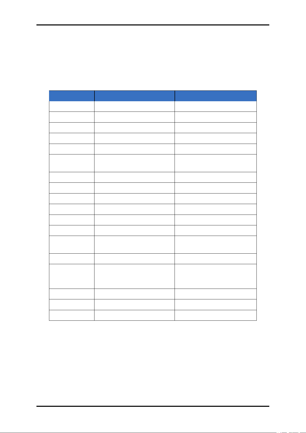
5.7 COMMANDS LIST
TFM260 uses several command types. Query - Returns the requested information about parameter settings from TFM260 . Update - Updates parameters in SQM-160. Remote - Performs
an action. Status - Reads system status information. Several commands can act as more than
one command type, depending on how they are sent. For example, the A command can be
used to query or update Film parameters.
www.beamtec.de ; e-mail: [email protected] tel.: +49 731 146620 0
Wolfgang-Paul-Str. 4, 89081 Ulm, Germany
BeamTec
Page 51
51 TFM260 Thin Film Monitor
Command Command Type Parameters send/Returned
@ Query TFM260 Version
A Query/Update Film Parameters
B Query/Update System 1 Parameters
C Query/Update System 2 Parameters
D Update Set Active Film
J Query Number of Installed Sensor
Channels
L Status Current Sensor Rate
M Status Current Average Rate
N Status Current Sensor Thickness
O Status Current Average Thickness
P Status Current Sensor Frequency
R Status Crystal Life
S Remote Zero Average Thickness
and Rate
T Remote Zero Time
U Remote/Status Toggle Source Shutter
Open/Close
Query Source Shutter State
W Status Rate, Thickness, Frequency
Y Status Power-Up Reset Flag State
Z Update Default All Parameters
Table 5.3: TFM260 commands
www.beamtec.de ; e-mail: [email protected] tel.: +49 731 146620 0
Wolfgang-Paul-Str. 4, 89081 Ulm, Germany
BeamTec
Page 52
TFM260 Thin Film Monitor 52
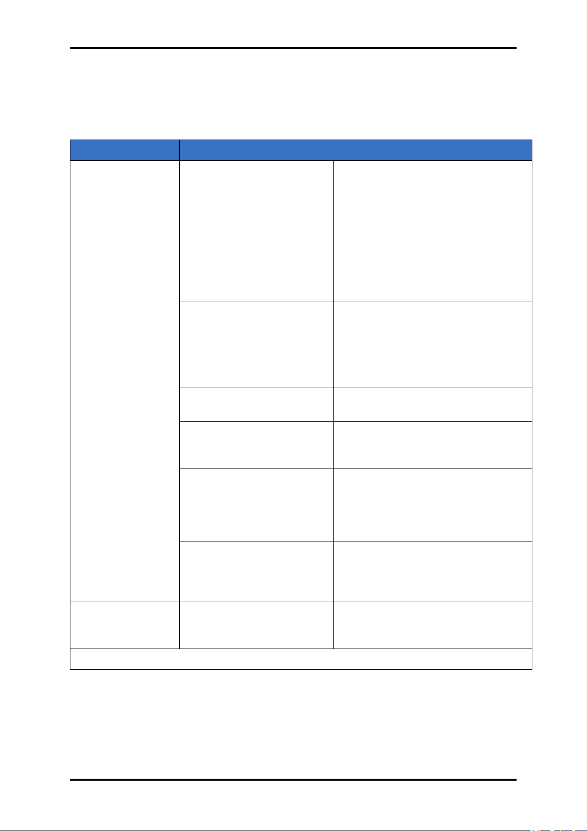
6 TROUBLESHOOTING
SYMPTOM CAUSE REMEDY
Frequency reading
in Sensor Information screen is
unstable or drifting
(not a normal frequency decrease
associated with
material being
deposited on the
crystal).
Temperature of the crystal
is unstable (an AT-cut crystal may drift as much as 10
Hz/°C).
Humidity level on the crystal
is changing. Moisture being
absorbed or exuded from the
crystal surface.
Defective in-vacuum cable
or coax cables.
Crystal seating on the crystal
holder surface is scratched
or contaminated.
Control the vacuum chamber temperature.
Move the crystal farther away from the
source (at least 25cm from source).
Check sensor water cooling for correct flow and temperature. Refer to
the sensor operating manual.
Clean or replace the crystal holder.
Refer to the sensor operating manual.
Avoid condensation by turning off
cooling water to sensor before opening the vacuum chamber to air. Flow
water above the dew point of the room
through the sensor when the chamber
is open.
Use an ohmmeter to check electrical
continuity and isolation.
Clean or replace crystal holder. Refer
to the sensor operating manual.
TFM260 does not
turn on.
TFM260 or oscillator is malfunctioning.
Excessive cable length between oscillator and crystal causes a self-oscillation
condition.
Line cord is not plugged into
TFM260 or rear panel power
switch is not on.
Test the TFM260 and oscillator using the test crystal module(see section
9.3)
Substitute a known good TFM260 .
Substitute a known good oscillator.
Use no longer than a 90 cm in-vacuum
cable. Use only the 15 cm cable
between TFM260 or oscillator and
feedthrough.
Connect line cord. Set the rear panel
power switch to position 1 (ON).
continued on next page
www.beamtec.de ; e-mail: [email protected] tel.: +49 731 146620 0
Wolfgang-Paul-Str. 4, 89081 Ulm, Germany
BeamTec
Page 53
53 TFM260 Thin Film Monitor
continued from previous page
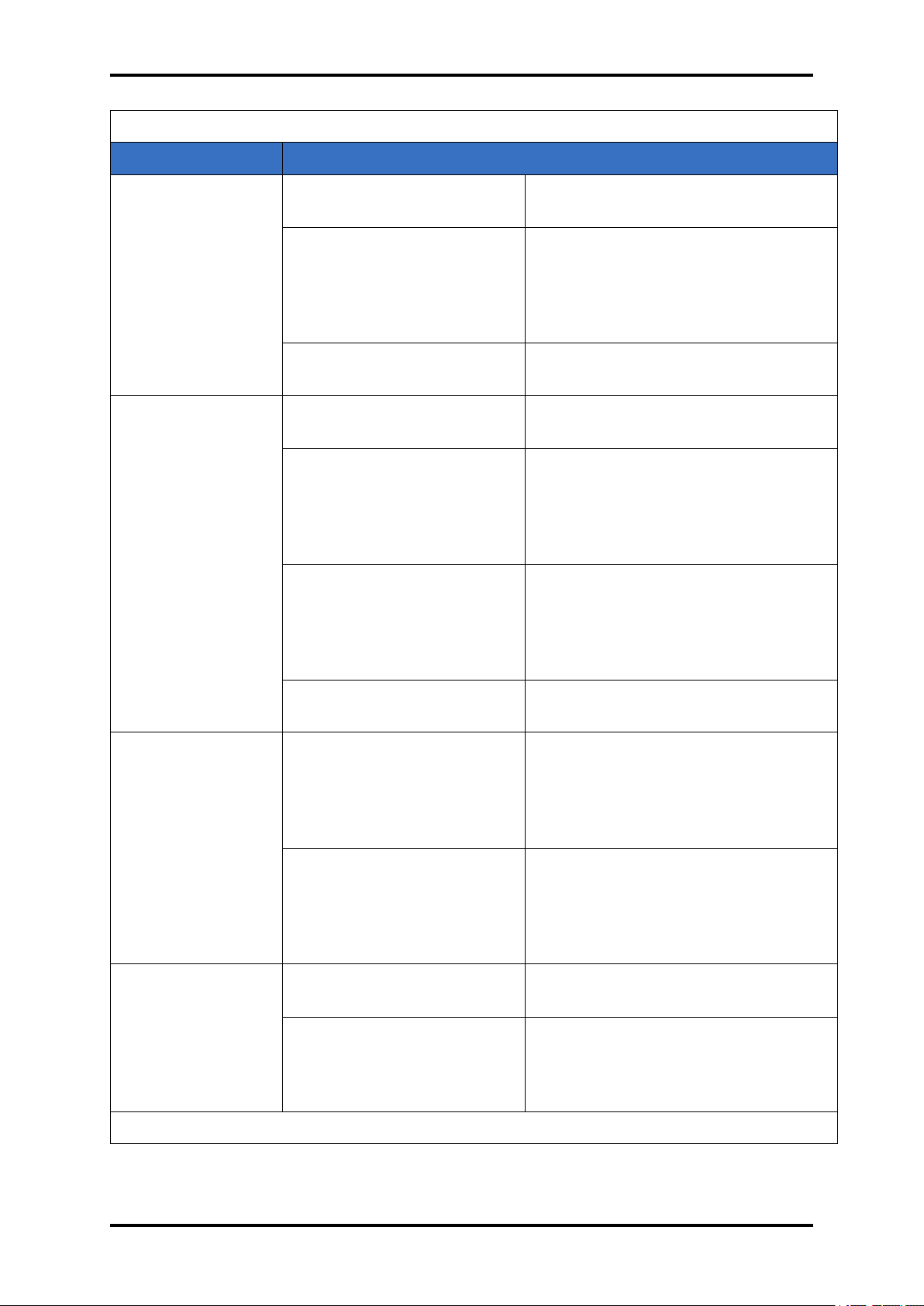
SYMPTOM CAUSE REMEDY
Incorrect line voltage. Line voltage must be within TFM260
line voltage specification
Fuse open. Remove the fuse drawer from the
power inlet and examine both fuses,
or use an ohmmeter to check the
fuses. Replace open fuses with the
specified fuse
TFM260 is malfunctioning. Contact the device manufacturer de-
partment
TFM260 “locks
up.”.
Frequency reading
in Sensor Information screen is an incorrect value.
Covers / panels not installed
or not secured.
Electrical noise is being
picked up by cables connected to TFM260 .
Install / securely fasten all covers and
panels.
Locate the sensor, oscillator cables,
source output cables, I/O cables, and
line cord at least 30cm away from high
voltage / high power cables and other
sources of electrical noise.
Inadequate system grounding.
Ground wires or straps should be
short with large surface area to minimize impedance to ground. Ground
wires or straps must connect to an appropriate earth ground
TFM260 is malfunctioning. Contact the device manufacturer de-
partment
Excessive cable length between oscillator and crystal
is causing a self-oscillation
at a frequency different than
In-vacuum cable length should not exceed 80 cm.
Use the 15.2 cm cable between oscillator and feedthrough
the crystal frequency.
Crystal Fail is displayed.
TFM260 or oscillator is malfunctioning.
Test the TFM260 and oscillator using the test crystal module(see section
9.3)
Substitute a known good TFM260 .
Substitute a known good oscillator.
Failed or defective crystal, or
Install a new crystal.
no crystal in sensor.
Two crystals were installed
or crystal is upside down.
Remove extra crystal. Reverse crystal orientation. Inspect crystal for
scratches; if scratched, replace with
new crystal.
www.beamtec.de ; e-mail: [email protected] tel.: +49 731 146620 0
Wolfgang-Paul-Str. 4, 89081 Ulm, Germany
BeamTec
continued on next page
Page 54

TFM260 Thin Film Monitor 54
continued from previous page
SYMPTOM CAUSE REMEDY
Crystal Fail is displayed
Build-up of material at crystal holder aperture is touching the crystal.
Crystal frequency is not
within the frequency range
of TFM260
Oscillator and sensor not
connected to the Sensor
channel(s)
Sensor not connected, or
bad electrical connection in
sensor head or feedthrough,
or bad cables.
Clean or replace the crystal holder.
Refer to the sensor operating manual.
Use a crystal with starting frequency
appropriate for TFM260 frequency
range.
Change the Min / Max Frequency settings in the
Connect oscillator and sensor to all
active Sensor channel(s).
Check sensor connections. Refer to
the sensor operating manual.
Use an ohmmeter to check electrical
continuity / isolation of sensor head,
feedthrough, in-vacuum cable, BNC
adapter cable, and BNC cables. Refer to the sensor operating manual.
Substitute a 5.5 MHz test crystal or
a known good sensor for the suspect
sensor.
Bad coax cable between
feedthrough and TFM260 or
oscillator, or bad coax cable between oscillator and
TFM260 .
TFM260 or QMB6-EO is
malfunctioning.
Use an ohmmeter to check electrical continuity / isolation. Substitute a
known good coax cable.
Substitute a known good TFM260 (or
other quartz monitor).
Substitute a known good oscillator.
Substitute known good BNC cables.
Substitute a known good in-vacuum
cable.
Substitute a known good sensor/feedthrough
Test the TFM260 and oscillator using
the test crystal module(see section
9.3)
continued on next page
www.beamtec.de ; e-mail: [email protected] tel.: +49 731 146620 0
Wolfgang-Paul-Str. 4, 89081 Ulm, Germany
BeamTec
Page 55
55 TFM260 Thin Film Monitor
continued from previous page
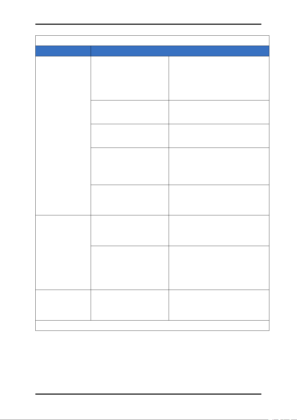
SYMPTOM CAUSE REMEDY
Crystal Fail is
displayed during deposition
before “normal”
life of crystal is
exceeded.
Crystal is being hit by small
droplets of molten material
from the evaporation source.
Damaged crystal or deposited material is causing
stress to crystal.
Material build-up on crystal
holder is partially masking
the crystal surface.
Shutter is partially obstructing deposition flux or sensor
is poorly positioned, causing
uneven distribution of material on crystal.
Crystal oscillation is weak
due to excessive cable
length between oscillator
and crystal.
Use a shutter to shield the sensor during source conditioning.
Move the crystal farther away (at least
25cm) from the source.
Replace the crystal. Use an Alloy
crystal if appropriate for deposited material.
Clean or replace the crystal holder.
Refer to the sensor operating manual
for cleaning instructions.
Visually check crystal for an uneven
coating, and if present, correct shutter
or sensor positioning problem.
In-vacuum cable length should not exceed 80 cm
Use the 15 cm cable between oscillator and feedthrough.
Crystal Fail is displayed when vacuum chamber is
opened to air.
Rate, Thickness,
and Frequency
readings are
noisy.
Crystal was near the end
of its life; opening to air
causes film oxidation, which
increases film stress.
Excessive moisture accumulation on the crystal.
Excessive cable length between oscillator and crystal.
Replace the crystal.
Avoid condensation by turning off
cooling water to sensor before opening the vacuum chamber to air, and
then flow heated water above the dew
point of the room through the sensor
when the chamber is open.
In-vacuum cable length should not exceed 80 cm
Use the 15 cm cable between oscillator and feedthrough.
continued on next page
www.beamtec.de ; e-mail: [email protected] tel.: +49 731 146620 0
Wolfgang-Paul-Str. 4, 89081 Ulm, Germany
BeamTec
Page 56
TFM260 Thin Film Monitor 56
continued from previous page
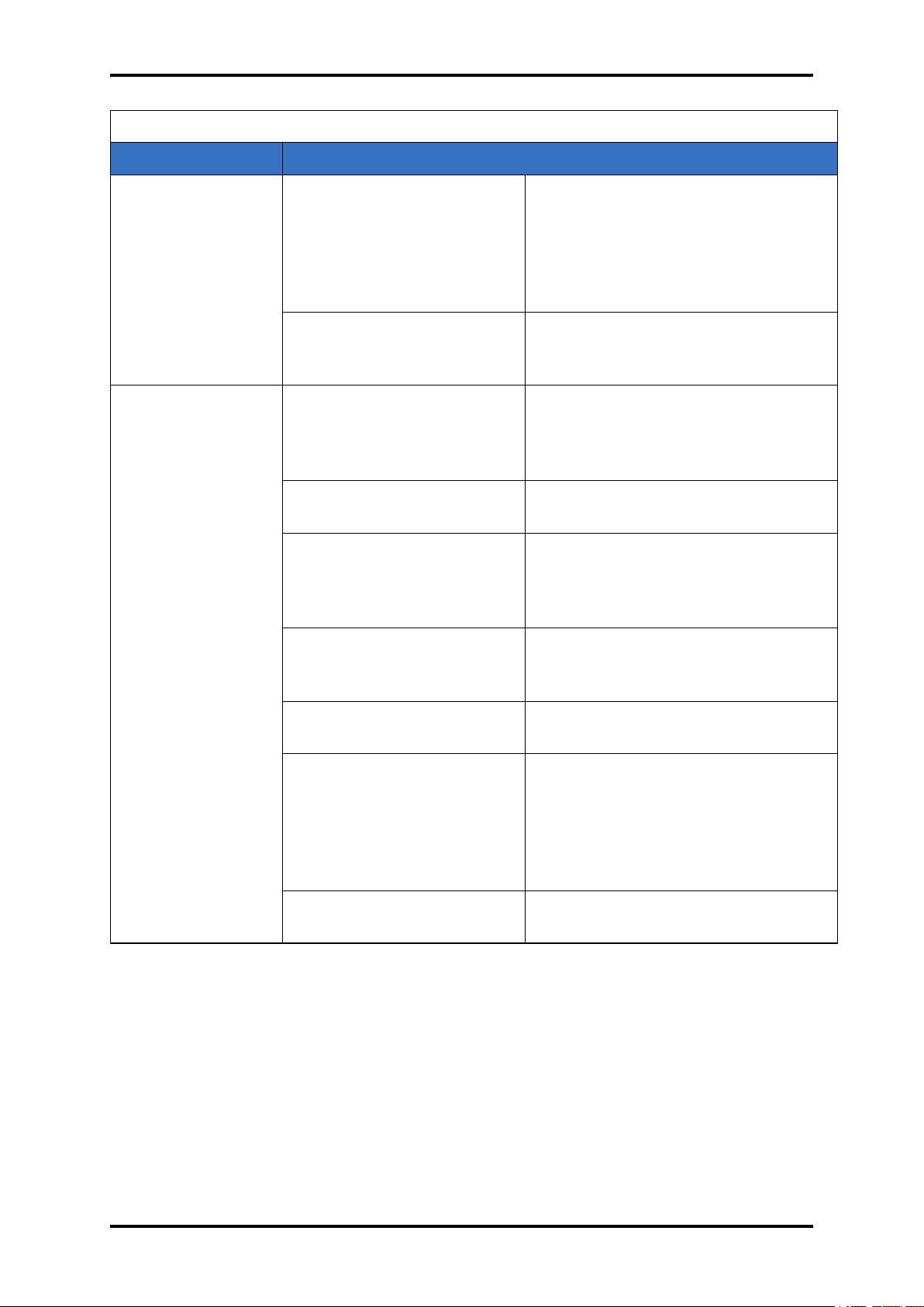
SYMPTOM CAUSE REMEDY
Thickness reading
has large excursions during deposition.
Electrical noise is being
picked up by cables connected to TFM260 .
Inadequate system grounding.
Mode hopping due to damaged crystal.
Crystal is near the end of its
life.
Scratches or foreign particles on the crystal holder
crystal seating surface.
Locate the sensor, oscillator cables,
source output cables, I/O cables,
communications cable, and line cord
at least 30 cm away from high Voltage
/ high power cables and other sources
of electrical noise.
Ground wires or straps should be
short with large surface area to minimize impedance to ground.
Replace the crystal.
Replace the crystal.
Clean the crystal seating surface inside the crystal holder or replace crystal holder. Refer to sensor operating
manual for cleaning instructions
Uneven coating onto crystal. A straight line from center of source to
center of crystal should be perpendicular to face of crystal.
Particles on crystal. Replace crystal.
Remove source of particles.
Intermittent cables or connections.
Use an ohmmeter to check electrical continuity / isolation of sensor
head, feedthrough, in-vacuum cable,
and BNC cables. Refer to the sensor operating manual for detailed troubleshooting information.
Inadequate cooling of crystal.
Check water flow rate and temperature for sensor cooling.
Table 6.1: Write device address
www.beamtec.de ; e-mail: [email protected] tel.: +49 731 146620 0
Wolfgang-Paul-Str. 4, 89081 Ulm, Germany
BeamTec
Page 57

7 CALIBRATION PROCEDURES
7.1 IMPORTANCE OF DENSITY, TOOLING AND Z-RATIO
The quartz crystal microbalance is capable of precisely measuring the mass added to the face
of the oscillating quartz crystal sensor. The density of this added material allows conversion of
the mass information into thickness. In some instances, where highest accuracy is required, it
is necessary to make a density calibration as outlined in section 7.2.
Because the flow of material from a deposition is not uniform, it is necessary to account for
the different amount of material flow onto the sensor compared to the substrates. This factor
is accounted for in the tooling factor. The tooling factor can be experimentally established by
following the guidelines in section 7.3.
If the Z-Ratio is not known, it could be estimated from the procedures outlined in section 7.4.
7.2 DETERMINING DENSITY
NOTE: The bulk density values retrieved from Table 8.1 are sufficiently accurate for most applications. Follow the steps below to determine density value.
1. Place a substrate (with proper masking for film thickness measurement) adjacent to the
sensor, so that the same thickness will be accumulated on the crystal and substrate.
2. Set density to the bulk value of the film material or to an approximate value.
3. Set Z-Ratio to 1.000 and tooling to 100
4. Place a new crystal in the sensor and make a short deposition (1000 to 5000 Å).
5. After deposition, remove the test substrate and measure the film thickness with either a
multiple beam interferometer or a stylus-type profilometer.
6. Determine the new density value with equation [1]:
𝑇
𝐷𝑒𝑛𝑠𝑖𝑡𝑦(𝑔/𝑐𝑚) = 𝐷(
where:
• 𝐷= Initial density setting
• 𝑇= Thickness reading on TFM260
• 𝑇= Measured thickness
7. A quick check of the calculated density may be made by programming TFM260 with the
new density value and observing that the displayed thickness is equal to the measured
thickness, provided that the thickness displayed on TFM260 has not been zeroed between
the test deposition and entering the calculated density.
) (7.1)
𝑇
NOTE: Slight adjustment of density may be necessary in order to achieve Tx = Tm.
57
Page 58

TFM260 Thin Film Monitor 58
7.3 DETERMINING TOOLING
1. Place a test substrate in the system substrate holder.
2. Make a short deposition and determine actual thickness.
3. Calculate tooling from the relationship shown in equation:
𝑇
𝑇𝑜𝑜𝑙𝑖𝑛𝑔(%) = 𝑇𝐹(
where:
• 𝑇= Actual thickness at substrate holder
• 𝑇= Thickness reading on TFM260
• 𝑇𝐹= Initial tooling factor
4. Round off percent tooling to the nearest 0.1%.
5. When entering this new value for tooling, 𝑇will equal 𝑇if calculations are done properly.
) (7.2)
𝑇
NOTE: It is recommended that a minimum of three separate evaporations be made when calibrating tooling. Variations in source distribution and other system factors will contribute to slight
thickness variations. An average value tooling factor should be used for final calibrations.
7.4 Laboratory Determination of Z-Ratio
A list of Z-Ratios for materials commonly used are available in 8.1. For other materials, Z can
be calculated from the following formula:
𝑑𝜇
𝑍 = (
𝑑𝜇𝑓
𝑍 = 9.378𝑥10(𝑑𝜇)(−
where:
• 𝑑= Density (𝑔/𝑐𝑚) of deposited film
• 𝜇= Shear modulus (𝑑𝑦𝑛𝑒𝑠/𝑐𝑚) of deposited film
• 𝑑= Density of quartz (crystal) (2.649𝑔/𝑐𝑚)
1
(
)
) (7.3)
2
1
) (7.4)
2
• 𝜇= Shear modulus of quartz (crystal) (3.32𝑥101𝑑𝑦𝑛𝑒𝑠/𝑐𝑚)
The densities and shear moduli of many materials can be found in a number of handbooks.
Laboratory results indicate that Z-Ratios of materials in thin-film form are very close to the bulk
values. However, for high stress producing materials, Z-Ratios of thin films are slightly smaller
than those of the bulk materials. For applications that require more precise calibration, the
following direct method is suggested:
www.beamtec.de ; e-mail: [email protected] tel.: +49 731 146620 0
Wolfgang-Paul-Str. 4, 89081 Ulm, Germany
BeamTec
Page 59

59 TFM260 Thin Film Monitor
1. Establish the correct density value as described in section 7.2.
2. Install a new crystal and record its starting frequency, 𝐹𝑜. The starting frequency will be
displayed on the TFM260 Main screen.
3. Make a deposition on a test substrate such that the percent crystal life display will read
approximately 50 %, or near the end of crystal life for the particular material, whichever is
smaller.
4. Stop the deposition and record the ending crystal frequency, 𝐹.
5. Remove the test substrate and measure the film thickness with either a multiple beam
interferometer or a stylus-type profilometer.
6. Using the density value from step 1 and the recorded values for 𝐹𝑜 and 𝐹, adjust the ZRatio value in thickness equation [5] to bring the calculated thickness value into agreement
with the actual thickness. If the calculated value of thickness is greater than the actual
thickness, increase the Z-Ratio value. If the calculated value of thickness is less than the
actual thickness, decrease the Z-Ratio value.
For multiple layer deposition (for example, two layers), the Z-Ratio used for the second layer is
determined by the relative thickness of the two layers. For most applications the following three
rules will provide reasonable accuracies:
• If the thickness of layer 1 is large compared to layer 2, use material 1 Z-Ratio for both
layers.
• If the thickness of layer 1 is thin compared to layer 2, use material 2 Z-Ratio for both layers.
• If the thickness of both layers is similar, use a value for Z-Ratio which is the weighted
average of the two Z-Ratios for deposition of layer 2 and subsequent layers.
www.beamtec.de ; e-mail: [email protected] tel.: +49 731 146620 0
Wolfgang-Paul-Str. 4, 89081 Ulm, Germany
BeamTec
Page 60

8 Measurement and Theory
The TFM260 utilizes the piezoelectric sensitivity of a quartz monitor crystal to added mass. The
TFM260 uses this mass sensitivity to control the deposition rate and final thickness of a vacuum
deposition. When a voltage is applied across the faces of a properly shaped piezoelectric crystal, the crystal is distorted and changes shape in proportion to the applied voltage. At certain
discrete frequencies of applied voltage, a condition of sharp electro-mechanical resonance is
encountered.
When mass is added to the face of a resonating quartz crystal, the frequency of these resonances are reduced. This change in frequency is very repeatable and is precisely understood
for specific oscillating modes of quartz. This heuristically easy-to-understand phenomenon is
the basis of an indispensable measurement and process control tool that can easily detect the
addition of less than an atomic layer of an adhered foreign material.
It is generally accepted that when the mass loading from the deposit causes a change in frequency of less than 2% of the frequency of the unloaded crystal, Sauerbrey’s equation can be
used to obtain accurate results in thin-film thickness calculations. As the thickness of the film
increases, the Sauerbrey equation must be extended to incorporate the elasticity of the deposit.
Lu and Lewis gave a simple equation for the calculation of the dependence of ∆f on ∆m, which
is currently applied by most Quartz Monitor users to calculate rigid thin-film thicknesses:
1
[
𝐴𝑇𝑎𝑛(𝑧 ⋅ 𝑇𝑎𝑛
𝐹
𝜋𝐹
𝐹
1
) −
𝐴𝑇𝑎𝑛(𝑧 ⋅ 𝑇𝑎𝑛(
𝐹
𝜋 ⋅ 𝐹
))] (8.1)
𝐹
𝑇=
𝑍⋅ 10
2𝜋 ⋅ 𝑧 ⋅ 𝑝
where:
𝑇Thicknes of deposided film (kA)
𝐹Starting frequency of the sensor crystal (Hz)
𝐹Final frequency of the sensor crystal (Hz)
𝐹Nominal blank frequency = 6045000(Hz)
𝑧 Z-Ratio of deposited film material
𝑍Specific acoustic impedance of quartz = 8765000(
𝑝 Density of deposited film
⋅
)
This analysis of frequency changes, including the acoustic impedances of the quartz and film, is
often called the “Z-match” method. The accuracy of the mass load and film thickness calculation
is often limited by how well the Z-Factor and density of the material are known. Density and
Z-Factor values are typically very close to bulk values. The bulk density and shear modulus
values for common film materials can be found in many material reference handbooks.
The Lu and Lewis equation is generally considered to be a good match to the experimental
results for frequency changes up to 40% (relative to the unloaded crystal). Keep also in mind
that the Z-match equation strictly applies to “rigid” deposits. Films which behave viscoelastically,
such as some organic polymer films with large thickness or viscosity, will exhibit significant
deviations from equation.
60
Page 61
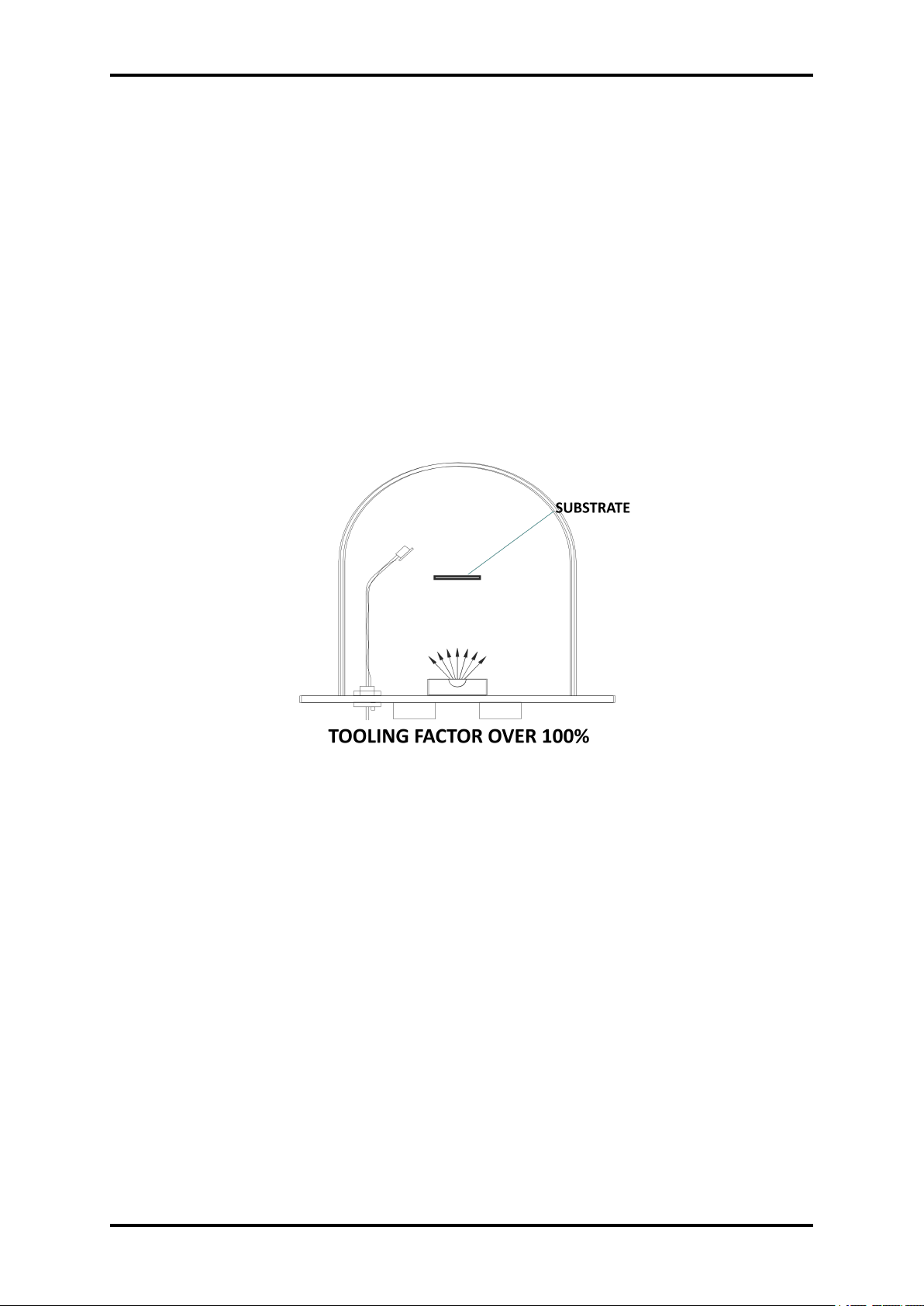
61 TFM260 Thin Film Monitor
Crystal failures are also often seen before a 40% shift in frequency is reached. Common problems are shorts in the crystal electrodes due to excessive buildup, mode hopping to other (anharmonic) resonant frequencies due to the buildup of composite resonant modes, deviations
from theory due to fringing electrode fields developed between the electrodes and the film, unexpected shifts in fundamental frequency due to stress build up on the crystal surface, splitting
of source material resulting in nonuniform films, etc.
8.1 TOLLING FACTOR
Tooling Factor is a correction for the difference in material deposited on the quartz sensor versus
the substrate. Illustrated below is an example of how difference in distance between the sensor
and substrate causes an incorrect reading as you would see in an electron or thermal evaporation system. It is impossible to place a sensor in exactly the same place as your substrate
unless the sensor is your substrate.
Figure 8.1: Tooling factor over 100%
www.beamtec.de ; e-mail: [email protected] tel.: +49 731 146620 0
Wolfgang-Paul-Str. 4, 89081 Ulm, Germany
BeamTec
Page 62
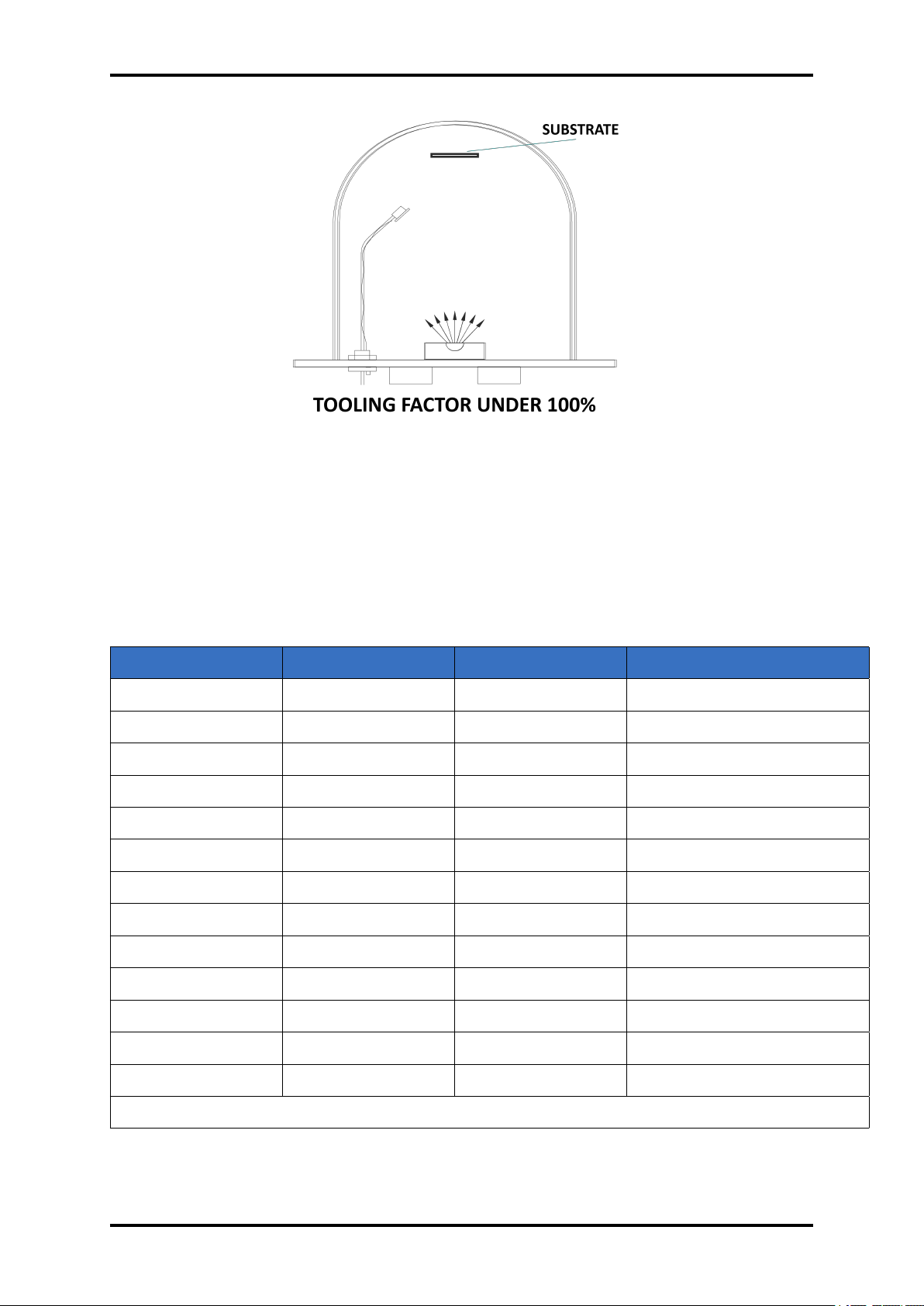
TFM260 Thin Film Monitor 62
Figure 8.2: Tooling factor under 100%
8.2 MATERIAL LIST
The following Table represents the density and Z-Ratio for various materials. The list is alphabetical by chemical formula An * is used to indicate that a Z-Ratio has not been established for
a certain material. A value of 1.000 is defaulted in these situations.
Formula Density Z-Ratio Material Name
𝐴𝑔 10.500 0.539 silver
𝐴𝑔𝐵𝑟 6.470 1.180 silver bromide
𝐴𝑔𝐶𝑙 5.560 1.320 silver chloride
𝐴𝑙 2.700 1.080 aluminum
𝐴𝑙𝑂
𝐴𝑙𝐶
𝐴𝐼𝐹
3.970 0.336 aluminum oxide
2.360 *1.000 aluminum carbide
3.070 *1.000 aluminum fluoride
𝐴𝐼𝑁 3.260 *1.000 aluminum nitride
𝐴𝑙𝑆𝑏 4.360 0.743 aluminum antimonide
𝐴𝑠 5.730 0.966 arsenic
𝐴𝑠𝑆𝑒
4.750 *1.000 arsenic selenide
𝐴𝑢 19.300 0.381 gold
𝐵 2.370 0.389 boron
www.beamtec.de ; e-mail: [email protected] tel.: +49 731 146620 0
Wolfgang-Paul-Str. 4, 89081 Ulm, Germany
BeamTec
continued on next page
Page 63
63 TFM260 Thin Film Monitor
continued from previous page
Formula Density Z-Ratio Material Name
𝐵0
1.820 *1.000 boron oxide
𝐵𝐶 2.370 *1.000 boron carbide
𝐵𝑁 1.860 *1.000 boron nitride
𝐵𝑎 3.500 2.100 barium
𝐵𝑎𝐹
𝐵𝑎𝑁𝑂
4.886 0.793 barium fluoride
3.244 1.261 barium nitrate
𝐵𝑎𝑂 5.720 *1.000 barium oxide
𝐵𝑎𝑇𝑖𝑂
𝐵𝑎𝑇𝑖𝑂
5.999 0.464 barium titanate (tetr)
6.035 0.412 barium titanate (cubic)
𝐵𝑒 1.850 0.543 beryllium
𝐵𝑒𝐹
1.990 *1.000 beryllium fluoride
𝐵𝑒𝑂 3.010 *1.000 beryllium oxide
𝐵𝑖 9.800 0.790 bismuth
𝐵𝑖𝑂
8.900 *1.000 bismuth oxide
𝐵𝑖𝑆
𝐵𝑖𝑆𝑒
𝐵𝑖𝑇𝑒
𝐵𝑖𝐹
7.390 *1.000 bismuth trisulfide
6.820 *1.000 bismuth selenide
7.700 *1.000 bismuth telluride
5.320 *1.000 bismuth fluoride
𝐶 2.250 3.260 carbon (graphite)
𝐶 3.520 0.220 carbon (diamond)
𝐶𝐻
1.100 *1.000 parlyene (union carbide)
𝐶𝑎 1.550 2.620 calcium
𝐶𝑎𝐹
3.180 0.775 calcium fluoride
𝐶𝑎𝑂 3.350 *1.000 calcium oxide
𝐶𝑎𝑂 − 𝑆𝑖𝑂
𝐶𝑎𝑆𝑂
𝐶𝑎𝑇𝑖𝑂
𝐶𝑎𝑊𝑂
2.900 *1.000 calcium silicate (3)
2.962 0.955 calcium sulfate
4.100 *1.000 calcium titanate
6.060 *1.000 calcium tungstate
𝐶𝑑 8.640 0.682 cadmium
continued on next page
www.beamtec.de ; e-mail: [email protected] tel.: +49 731 146620 0
Wolfgang-Paul-Str. 4, 89081 Ulm, Germany
BeamTec
Page 64
TFM260 Thin Film Monitor 64
continued from previous page
Formula Density Z-Ratio Material Name
𝐶𝑑𝐹
6.640 *1.000 cadmium fluoride
𝐶𝑑𝑂 8.150 *1.000 cadmium oxide
𝐶𝑑𝑆 4.830 1.020 cadmium sulfide
𝐶𝑑𝑆𝑒 5.810 *1.000 cadmium selenide
𝐶𝑑𝑇𝑒 6.200 0.980 cadmium telluride
𝐶𝑒 6.780 *1.000 cerium
𝐶𝑒𝐹
𝐶𝑒𝑂
6.160 *1.000 cerium (III) fluoride
7.130 *1.000 cerium (IV) dioxide
𝐶𝑜 8.900 0.343 cobalt
𝐶𝑜𝑂 6.440 0.412 cobalt oxide
𝐶𝑟 7.200 0.305 chromium
𝐶𝑟𝑂
𝐶𝑟𝐶
5.210 *1.000 chromium (III) oxide
6.680 *1.000 chromium carbide
𝐶𝑟𝐵 6.170 *1.000 chromium boride
𝐶𝑠 1.870 *1.000 cesium
𝐶𝑠𝑆𝑂
4.243 1.212 cesium sulfate
𝐶𝑠𝐵𝑟 4.456 1.410 cesium bromide
𝐶𝑠𝐶𝐼 3.988 1.399 cesium chloride
𝐶𝑠𝐼 4.516 1.542 cesium iodide
𝐶𝑢 8.930 0.437 copper
𝐶𝑢𝑂 6.000 *1.000 copper oxide
𝐶𝑢𝑆 5.600 0.690 copper (I) sulfide (alpha)
𝐶𝑢𝑆 5.800 0.670 copper (I) sulfide (beta)
𝐶𝑢𝑆 4.600 0.820 copper (II) sulfide
𝐷𝑦 8.550 0.600 dysprosium
𝐷𝑌𝑂
7.810 *1.000 dysprosium oxide
𝐸𝑟 9.050 0.740 erbium
𝐸𝑟𝑂
8.640 *1.000 erbium oxide
𝐸𝑢 5.260 *1.000 europium
continued on next page
www.beamtec.de ; e-mail: [email protected] tel.: +49 731 146620 0
Wolfgang-Paul-Str. 4, 89081 Ulm, Germany
BeamTec
Page 65
65 TFM260 Thin Film Monitor
continued from previous page
Formula Density Z-Ratio Material Name
𝐸𝑢𝐹
6.500 *1.000 europium fluoride
𝐹𝑒 7.860 0.349 iron
𝐹𝑒𝑂
5.240 *1.000 iron oxide
𝐹𝑒𝑂 5.700 *1.000 iron oxide
𝐹𝑒𝑆 4.840 *1.000 iron sulfide
𝐺𝑎 5.930 0.593 gallium
𝐺𝑎𝑂
5.880 *1.000 gallium oxide (B)
𝐺𝑎𝐴𝑠 5.310 1.590 gallium arsenide
𝐺𝑎𝑁 6.100 *1.000 gallium nitride
𝐺𝑎𝑃 4.100 *1.000 gallium phosphide
𝐺𝑎𝑆𝑏 5.600 *1.000 gallium antimonide
𝐺𝑑 7.890 0.670 gadolinium
𝐺𝑑𝑂
7.410 *1.000 gadolinium oxide
𝐺𝑒 5.350 0.516 germanium
𝐺𝑒𝑁
𝐺𝑒𝑂
5.200 *1.000 germanium nitride
6.240 *1.000 germanium oxide
𝐺𝑒𝑇𝑒 6.200 *1.000 germanium telluride
𝐻𝑓 13.090 0.360 hafnium
𝐻𝑓𝐵
10.500 *1.000 hafnium boride
𝐻𝑓𝐶 12.200 *1.000 hafnium carbide
𝐻𝑓𝑁 13.800 *1.000 hafnium nitride
𝐻𝑓𝑂
𝐻𝑓𝑆𝑖
9.680 *1.000 hafnium oxide
7.200 *1.000 hafnium silicide
𝐻𝑔 13.460 0.740 mercury
𝐻𝑜 8.800 0.580 holmium
𝐻𝑂
8.410 *1.000 holmium oxide
𝐼𝑛 7.300 0.841 indium
𝐼𝑛𝑂
7.180 *1.000 indium sesquioxide
𝐼𝑛𝑆𝑒
5.700 *1.000 indium selenide
continued on next page
www.beamtec.de ; e-mail: [email protected] tel.: +49 731 146620 0
Wolfgang-Paul-Str. 4, 89081 Ulm, Germany
BeamTec
Page 66
TFM260 Thin Film Monitor 66
continued from previous page
Formula Density Z-Ratio Material Name
𝐼𝑛𝑇𝑒
5.800 *1.000 indium telluride
𝐼𝑛𝐴𝑠 5.700 *1.000 indium arsenide
𝐼𝑛𝑃 4.800 *1.000 indium phosphide
𝐼𝑛𝑆𝑏 5.760 0.769 indium antimonide
𝐼𝑟 22.400 0.129 iridium
𝐾 0.860 10.189 potassium
𝐾𝐵𝑟 2.750 1.893 potassium bromide
𝐾𝐶𝐼 1.980 2.050 potassium chloride
𝐾𝐹 2.480 *1.000 potassium fluoride
𝐾𝐼 3.128 2.077 potassium iodide
𝐿𝑎 6.170 0.920 lanthanum
𝐿𝑎𝑂
𝐿𝑎𝐵
𝐿𝑎𝐹
6.510 *1.000 lanthanum oxide
2.610 *1.000 lanthanum boride
5.940 *1.000 lanthanum fluoride
𝐿𝑖 0.530 5.900 lithium
𝐿𝑖𝐵𝑟 3.470 1.230 lithium bromide
𝐿𝑖𝐹 2.638 0.778 lithium fluoride
𝐿𝑖𝑁𝑏𝑂
4.700 0.463 lithium niobate
𝐿𝑢 9.840 *1.000 lutetium
𝑀𝑔 1.740 1.610 magnesium
𝑀𝑔𝐴𝑙𝑂
𝑀𝑔𝐴𝑙𝑂
𝑀𝑔𝐹
3.600 *1.000 magnesium aluminate
8.000 *1.000 spinel
3.180 0.637 magnesium fluoride
𝑀𝑔𝑂 3.580 0.411 magnesium oxide
𝑀𝑛 7.200 0.377 manganese
𝑀𝑛𝑂 5.390 0.467 manganese oxide
𝑀𝑛𝑆 3.990 0.940 manganese (II) sulfide
𝑀𝑜 10.200 0.257 molybdenum
𝑀𝑜𝐶 9.180 *1.000 molybdenum carbide
continued on next page
www.beamtec.de ; e-mail: [email protected] tel.: +49 731 146620 0
Wolfgang-Paul-Str. 4, 89081 Ulm, Germany
BeamTec
Page 67
67 TFM260 Thin Film Monitor
continued from previous page
Formula Density Z-Ratio Material Name
𝑀𝑜𝐵
𝑀𝑜𝑂
𝑀𝑜𝑆
7.120 *1.000 molybdenum boride
4.700 *1.000 molybdenum trioxide
4.800 *1.000 molybdenum disulfide
𝑁𝑎 0.970 4.800 sodium
𝑁𝑎𝐴𝐼𝐹
𝑁𝑎𝐴𝑙𝐹
2.900 *1.000 cryolite
2.900 *1.000 chiolite
𝑁𝑎𝐵𝑟 3.200 *1.000 sodium bromide
𝑁𝑎𝐶𝑙 2.170 1.570 sodium chloride
𝑁𝑎𝐶𝐼𝑂
2.164 1.565 sodium chlorate
𝑁𝑎𝐹 2.558 1.645 sodium fluoride
𝑁𝑎𝑁𝑂
2.270 1.194 sodium nitrate
𝑁𝑏 8.578 0.492 niobium(columbium)
𝑁𝑏𝑂
𝑁𝑏𝑂
7.500 *1.000 niobium trioxide
4.470 *1.000 niobium (V) oxide
𝑁𝑏𝐵
6.970 *1.000 niobium boride
𝑁𝑏𝐶 7.820 *1.000 niobium carbide
𝑁𝑏𝑁 8.400 *1.000 niobium nitride
𝑁𝑑 7.000 *1.000 neodymium
𝑁𝑑𝑂
7.240 *1.000 neodymium oxide
𝑁𝑑𝐹3 6.506 *1.000 neodymium fluoride
𝑁𝑖 8.910 0.331 nickel
𝑁𝑖𝐶𝑟 8.500 *1.000 nichrome
𝑁𝑖𝐶𝑟𝐹𝑒 8.500 *1.000 Inconel
𝑁𝑖𝐹𝑒 8.700 *1.000 permalloy
𝑁𝑖𝐹𝑒𝑀𝑜 8.900 *1.000 supermalloy
𝑁𝑖𝑂 7.450 *1.000 nickel oxide
𝑃𝑁5 2.510 *1.000 phosphorus nitride
𝑃𝑏 11.300 1.130 lead
𝑃𝑏𝐶𝑙
5.850 *1.000 lead chloride
continued on next page
www.beamtec.de ; e-mail: [email protected] tel.: +49 731 146620 0
Wolfgang-Paul-Str. 4, 89081 Ulm, Germany
BeamTec
Page 68
TFM260 Thin Film Monitor 68
continued from previous page
Formula Density Z-Ratio Material Name
𝑃𝑏𝐹
8.240 0.661 lead fluoride
𝑃𝑏𝑂 9.530 *1.000 lead oxide
𝑃𝑏𝑆 7.500 0.566 lead sulfide
𝑃𝑏𝑆𝑒 8.100 *1.000 lead selenide
𝑃𝑏𝑆𝑛𝑂
8.100 *1.000 lead stannate
𝑃𝑏𝑇𝑒 8.160 0.651 leadtelluride
𝑃𝑑 12.038 0.357 palladium
𝑃𝑑𝑂 8.310 *1.000 palladium oxide
𝑃𝑜 9.400 *1.000 polonium
𝑃𝑟 6.780 *1.000 praseodymium
𝑃𝑟𝑂
6.880 *1.000 praseodymium oxide
𝑃𝑡 21.400 0.245 platinum
𝑃𝑡𝑂
10.200 *1.000 platinum oxide
𝑅𝑎 5.000 *1.000 radium
𝑅𝑏 1.530 2.540 rubidium
𝑅𝑏𝐼 3.550 *1.000 rubidium iodide
𝑅𝑒 21.040 0.150 rhenium
𝑅ℎ 12.410 0.210 rhodium
𝑅𝑢 12.362 0.182 ruthenium
𝑆8 2.070 2.290 sulfur
𝑆𝑏 6.620 0.768 antimony
𝑆𝑏𝑂
𝑆𝑏𝑆
5.200 *1.000 antimony trioxide
4.640 *1.000 antimony trisulfide
𝑆𝑐 3.000 0.910 scandium
𝑆𝑐𝑂
3.860 *1.000 scandium oxide
𝑆𝑒 4.810 0.864 selenium
𝑆𝑖 2.320 0.712 silicon
𝑆𝑖𝑁
3.440 *1.000 silicon nitride
𝑆𝑖𝐶 3.220 *1.000 silicon carbide
continued on next page
www.beamtec.de ; e-mail: [email protected] tel.: +49 731 146620 0
Wolfgang-Paul-Str. 4, 89081 Ulm, Germany
BeamTec
Page 69
69 TFM260 Thin Film Monitor
continued from previous page
Formula Density Z-Ratio Material Name
𝑆𝑖𝑂 2.130 0.870 silicon (II) oxide
𝑆𝑖𝑂
2.648 1.000 silicon dioxide
𝑆𝑚 7.540 0.890 samarium
𝑆𝑚2𝑂
7.430 *1.000 samarium oxide
𝑆𝑛 7.300 0.724 tin
𝑆𝑛𝑂
6.950 *1.000 tin oxide
𝑆𝑛𝑆 5.080 *1.000 tin sulfide
𝑆𝑛𝑆𝑒 6.180 *1.000 tin selenide
𝑆𝑛𝑇𝑒 6.440 *1.000 tin telluride
𝑆𝑟 2.600 *1.000 strontium
𝑆𝑟𝐹
4.277 0.727 strontium fluoride
𝑆𝑟𝑂 4.990 0.517 strontium oxide
𝑇𝑎 16.600 0.262 tantalum
𝑇𝑎2𝑂
𝑇𝑎𝐵
8.200 0.300 tantalum (V) oxide
11.150 *1.000 tantalum boride
𝑇𝑎𝐶 13.900 *1.000 tantalum carbide
𝑇𝑎𝑁 16.300 *1.000 tantalum nitride
𝑇𝑏 8.270 0.660 terbium
𝑇𝑐 11.500 *1.000 technetium
𝑇𝑒 6.250 0.900 tellurium
𝑇𝑒𝑂
5.990 0.862 tellurium oxide
𝑇ℎ 11.694 0.484 thorium
𝑇ℎ𝐹
𝑇ℎ𝑂
𝑇ℎ𝑂𝐹
6.320 *1.000 thorium (IV) fluoride
9.860 0.284 thorium dioxide
9.100 *1.000 thorium oxyfluoride
𝑇𝑖 4.500 0.628 titanium
𝑇𝑖0
𝑇𝑖𝐵
4.600 *1.000 titanium sesquioxide
4.500 *1.000 titanium boride
𝑇𝑖𝐶 4.930 *1.000 titanium carbide
Wolfgang-Paul-Str. 4, 89081 Ulm, Germany
BeamTec
www.beamtec.de ; e-mail: [email protected] tel.: +49 731 146620 0
continued on next page
Page 70
TFM260 Thin Film Monitor 70
continued from previous page
Formula Density Z-Ratio Material Name
𝑇𝑖𝑁 5.430 *1.000 titanium nitride
𝑇𝑖𝑂 4.900 *1.000 titanium oxide
𝑇𝑖𝑂
4.260 0.400 titanium (IV) oxide
𝑇𝐼 11.850 1.550 thallium
𝑇𝐼𝐵𝑟 7.560 *1.000 thallium bromide
𝑇𝐼𝐶𝐼 7.000 *1.000 thallium chloride
𝑇𝐼𝐼 7.090 *1.000 thallium iodide (B)
𝑈 19.050 0.238 uranium
𝑈𝑂
𝑈𝑂
𝑈𝑂
8.300 *1.000 tri uranium octoxide
10.969 0.348 uranium oxide
10.970 0.286 uranium dioxide
𝑉 5.960 0.530 vanadium
𝑉𝑂
𝑉𝐵
3.360 *1.000 vanadium pentoxide
5.100 *1.000 vanadium boride
𝑉𝐶 5.770 *1.000 vanadium carbide
𝑉𝑁 6.130 *1.000 vanadium nitride
𝑉𝑂
4.340 *1.000 vanadium dioxide
𝑊 19.300 0.163 tungsten
𝑊𝐵
10.770 *1.000 tungsten boride
𝑊𝐶 15.600 0.151 tungsten carbide
𝑊𝑂
𝑊𝑆
𝑊𝑆𝑖
7.160 *1.000 tungsten trioxide
7.500 *1.000 tungsten disulfide
9.400 *1.000 tungsten silicide
𝑌 4.340 0.835 yttrium
𝑌0
5.010 *1.000 yttrium oxide
𝑌𝑏 6.980 1.130 ytterbium
𝑌𝑏𝑂
9.170 *1.000 ytterbium oxide
𝑍𝑛 7.040 0.514 zinc
𝑍𝑛𝑆𝑏
6.300 *1.000 zinc antimonide
continued on next page
www.beamtec.de ; e-mail: [email protected] tel.: +49 731 146620 0
Wolfgang-Paul-Str. 4, 89081 Ulm, Germany
BeamTec
Page 71
71 TFM260 Thin Film Monitor
continued from previous page
Formula Density Z-Ratio Material Name
𝑍𝑛𝐹
4.950 *1.000 zinc fluoride
𝑍𝑛𝑂 5.610 0.556 zinc oxide
𝑍𝑛𝑆 4.090 0.775 zinc sulfide
𝑍𝑛𝑆𝑒 5.260 0.722 zinc selenide
𝑍𝑛𝑇𝑒 6.340 0.770 zinc telluride
𝑍𝑟 6.490 0.600 zirconium
𝑍𝑟𝐵
6.080 *1.000 zirconium boride
𝑍𝑟𝐶 6.730 0.264 zirconium carbide
𝑍𝑟𝑁 7.090 *1.000 zirconium nitride
𝑍𝑟𝑂
5.600 *1.000 zirconium oxide
Table 8.1: Material table
www.beamtec.de ; e-mail: [email protected] tel.: +49 731 146620 0
Wolfgang-Paul-Str. 4, 89081 Ulm, Germany
BeamTec
Page 72

9 MAINTANCE AND SERVICE
9.1 MAINTANCE
The TFM260 does not require any special maintenance work.
9.2 CLEANING
For cleaning of the outside of the device, a slightly moistened cloth will usually do. Do not use
any aggressive or abrasive cleaning agents.
9.3 CHECK FOR CORRECT OPERATION - TEST QUARTZ
Using the QMB6-EO Oscillator with Test Quartz to help isolate persistent crystal fail problems.
To activate the test feature, press connect the Test Crystal to BNC connector. If TFM260 and the
oscillator are functioning correctly, the Sensor Information will display a Frequency of approximately 6.0 MHz while the Test Crystal is connected. If the Sensor Information screen continues
to display Frequency of zero while the Test Crystal is connected, the problem is either the programming of the sensor selection, in the electronics of the oscillator, or TFM260 .
9.4 FIRMWARE UPDATE
The device can be updated via the USB port on the front panel. To do this, download the
appropriate files from the manufacturer’s website and copy them to the USB stick. The unit
should be run in bootloader mode and perform the update procedure.
9.4.1 DOWNLOAD FIRMWARE FILE
The steps necessary to prepare a USB storage for updating the device’s software are described
below.
1. Download the latest files from the manufacturer’s website appropriate for the hardware
version of your device.
For the media to be detected correctly by the device it must be formatted in the FAT32
system.
2. Insert the USB drive into the USB connector on the computer
3. Copy the downloaded files to a USB storage medium to the root directory.
4. Remove correctly the media from the computer.
72
Page 73
73 TFM260 Thin Film Monitor
CAUTION
To avoid unwanted device behaviour during the update, it is recommended
that the USB device be empty. It can not contain files with other programming
versions. Only the version you want to currently upload to the device.
9.4.2 DEVICE BOOT-LOADER MODE
In order to perform a software update, the device should be launched in the bootloader mode
as described below.
1. Turn the TFM260 OFF using the switch on the rear panel.
2. Insert USB storage into the USB port on the front panel of the TFM260 .
3. Press the knob and simultaneously turn on the power of the device using the button on
the back panel.
4. Release the knob button.
5. The screen should display a graphic like the one in the picture.
9.4.3 FIRMWARE UPDATE PROCEDURE
1. Follow the information on the screen.
2. If the USB stick is detected correctly, the following message will appear on the display:
Press Knob button to find firmware files
3. Press the Knob button to go to the next stage.
4. The device searches for files with software. The file names found are displayed on the
screen. Then TFM260 display message Press Knob button to start firmware update
5. Press the Knob button to go to the next stage.
6. The device performs thesoftware update procedure. It takes place in two stages: updating
the processor software responsible for the user interface and next updating the executive
processor software.
7. after the update is completed, the following message is displayed: Press Knob button to
run Main Application
8. Press the Knob button to run Main Application.
9. The device starts in normal mode and is ready for operation.
10. The update procedure has been completed
www.beamtec.de ; e-mail: [email protected] tel.: +49 731 146620 0
Wolfgang-Paul-Str. 4, 89081 Ulm, Germany
BeamTec
Page 74

10 STORAGE AND DISPOSAL
10.1 PACKING
Please retain the original packaging. The packaging is required for storing the device and for
shipping it to an authorized service center.
10.2 STORAGE
The TFM260 should only be stored in a dry room. The following requirements must be met:
PARAMETER VALUE
Ambient temperature -20...50°C
Humidity as low as possible; preferably in an
air-tight plastic bag with a desiccant
Table 10.1: Storage parameters
10.3 DISPOSAL
The product must be disposed of in accordance with the relevant local regulations for the environmentally safe disposal of systems and electronic components.
10.3.1 Waste Electrical and Electronic Equipment (WEEE)
The use of the WEEE symbol indicates that this product may not be treated as household
waste. By ensuring this product is disposed of correctly you will protect the environment. Recycling information of this product can be obtained at the place of sale, your household waste
disposal service provider, or local authority.
74
Page 75
75 TFM260 Thin Film Monitor
Figure 10.1: Waste Electrical and Electronic Equipment (WEEE) Symbol
www.beamtec.de ; e-mail: [email protected] tel.: +49 731 146620 0
Wolfgang-Paul-Str. 4, 89081 Ulm, Germany
BeamTec
Page 76

11 WARRANTY CONDITIONS
BeamTec warrants to the purchaser or end user of the equipment it sells that such equipment will
be free from defects in material and workmanship under normal use and service. This warranty
is for a period of 27 months from the date of original shipment or two years (24 months) from
the date the equipment is placed in use by the purchaser or end user thereof, whichever occurs
first. This warranty is void if the equipment is not used, operated, and maintained in accordance
with the manual accompanying the equipment. BeamTec shall not be responsible for any direct
or indirect loss or damage resulting from accident, negligence of a user, alteration, abuse, or
misuse of the equipment. Upon acceptance of this Limited Warranty, purchaser waives all
warranties, guarantee, or remedies not specifically stated in this Limited Warranty. This warranty
does not cover ordinary wear and tear or expendable components.
BeamTec obligation under this Limited Warranty is, at EDFelectronics’s option, to repair or replace any defective equipment or parts of the equipment, without charge to the purchaser, which
are returned, shipping prepaid, to the BeamTec facility. For return or repair of equipment, purchaser must contact BeamTec for a Return Materials Authorization (RMA) prior to shipment
of the equipment to BeamTec . If BeamTec has designated an Authorized Warranty Service
Representative in the purchaser’s country, contact may be made with the Authorized Warranty
Service Representative and defective equipment may be delivered to such Authorized Warranty
Service Representative to service warranty claims.
This warranty is in lieu of all other warranties, expressed or implied, including the implied warranties of merchantability and fitness for any particular purpose. The purchaser acknowledges
the purchaser is not relying in BeamTec skill or judgment to select or furnish equipment suitable
for any particular purpose.
76
 Loading...