

Beacon Morris 61000 BTU - HBB084 User Manual

INSTALLATION INSTRUCTIONS & PARTS LIST
HORIZONTAL STEAM AND HOT WATER UNIT HEATERS
ATTENTION: READ THIS MANUAL AND ALL LABELS ATTACHED TO THE UNIT CAREFULLY BEFORE
ATTEMPTING TO INSTALL, OPERATE OR SERVICE THESE UNITS! CHECK UNIT DATA PLATE FOR TYPE
OF GAS AND ELECTRICAL SPECIFICATIONS AND MAKE CERTAIN THAT THESE AGREE WITH THOSE AT
POINT OF INSTALLATION. RECORD THE UNIT MODEL AND SERIAL No.(s) IN THE SPACE PROVIDED.
RETAIN FOR FUTURE REFERENCE.
HIM-15
J30-05404
Model No.
Serial No.
Improper installation, adjustment, alteration,
service or maintenance can cause property damage,
injury or death. Read the installation, operating and
maintenance instructions thoroughly before installing or
servicing this equipment.
INSTALLER’S RESPONSIBILITY
Installer Please Note: This equipment has been tested and
inspected. It has been shipped free from defects from our
factory. However, during shipment and installation, problems
such as loose wires, leaks or loose fasteners may occur. It is
the installer’s responsibility to inspect and correct any
problems that may be found.
RECEIVING INSTRUCTIONS
Inspect shipment immediately when received to determine if
any damage has occurred to the unit during shipment. After
the unit has been uncrated, check for any visible damage to
the unit. Turn fan by hand to determine if damage has occurred.
If any damage is found, the consignee should sign the bill of
lading indicating such damage and immediately fi le claim for
damage with the transportation company.
07/11
260 NORTH ELM ST.
WESTFIELD, MA 01085
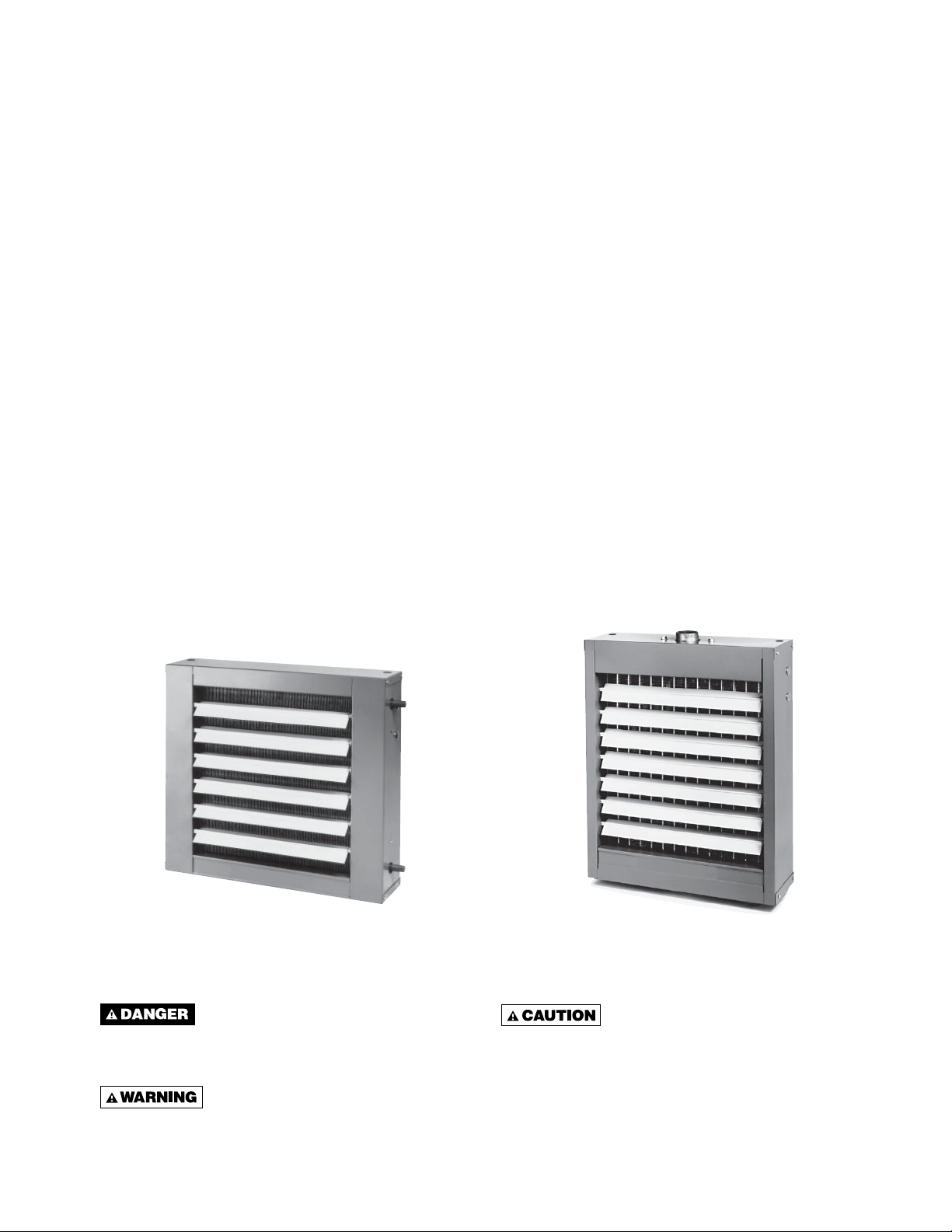
TABLE OF CONTENTS
GENERAL SAFETY INFORMATION .......................... 3
SPECIFICATIONS
Dimensional Data ..................................................4
Steam Performance Data .......................................5
Steam Calculations & Correction Factors ............... 6
Hot Water Performance Data .................................7
Hot Water Calculations & Correction Factors ........8
Technical Data ....................................................... 9
Motor Data ...........................................................10
LOCATION ................................................................ 11
INSTALLATION
Unit Mounting .......................................................12
Piping ...............................................................12-16
NOTICE: It is the owner’s responsibility to provide any scaffolding or other apparatus required to perform
emergency service or annual/periodic maintenance to this equipment.
ELECTRICAL CONNECTIONS ................................17
Operation ............................................................. 17
Thermostat Wiring and Location .......................... 17
WIRING INSTALLATION .......................................... 18
OPTIONS .................................................................19
MAINTENANCE .......................................................20
REPLACEMENT PARTS ..........................................21
TROUBLESHOOTING GUIDE .................................. 22
WARRANTY ..............................................................23
INSPECTION SHEET ................................................ 24
DESCRIPTION
Horizontal hydronic unit heaters are available in both
serpentine and header type units. Serpentine units offer
outputs from 8,030 to 35,900 BTU’s (2.4 to 10.5 kW) and
are ideal for hot water (only) installations with limited
clearances. Header type horizontal units range from
18,000 to 360,000 (5.3 to 105.5 kW) and can operate
with either hot water or steam. Both units are furnished
with totally enclosed motors, with explosion proof motors
as optional on header types. The designs are certifi ed
by ETL. Do not alter these units in any way and do
not attach any ductwork to the units. If you have
any questions after reading this manual, contact the
manufacturer.
Figure 1
Serpentine
Type
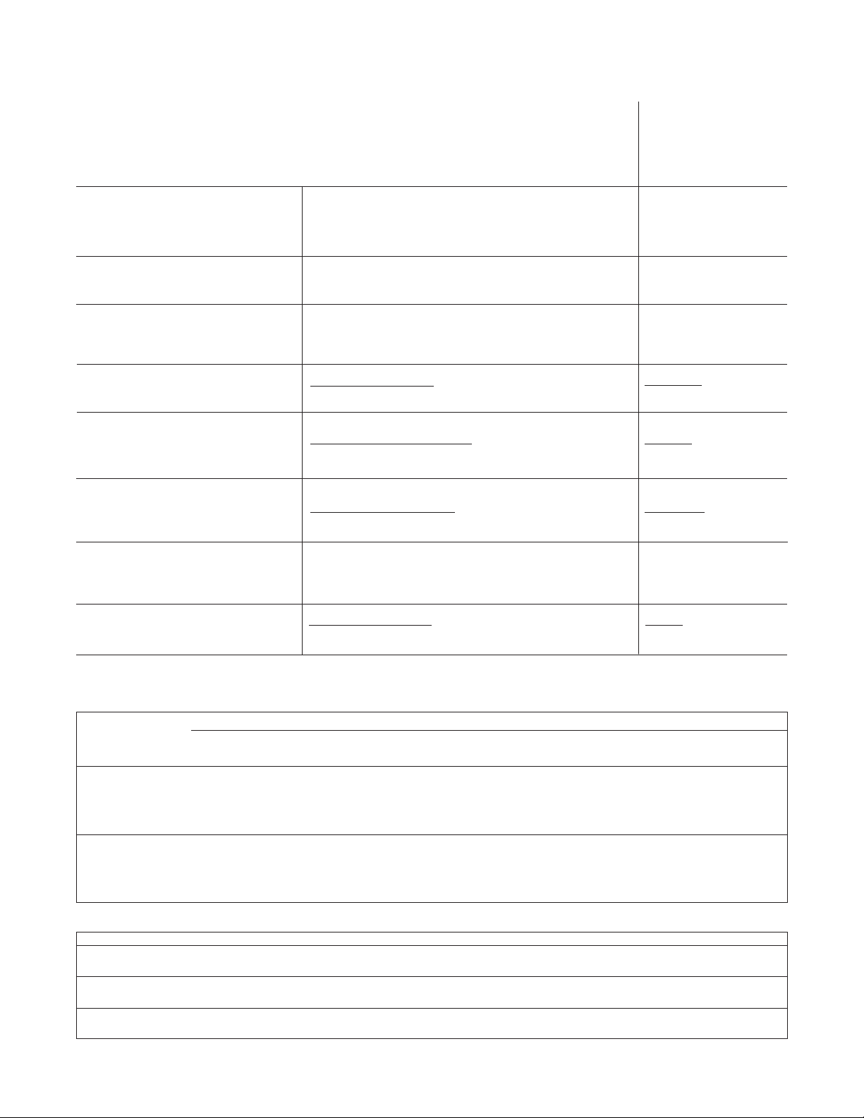
The following terms are used throughout this manual, in addition to ETL requirements, to bring attention to the
presence of potential hazards or to important information concerning the product:
Indicates an imminently hazardous
situation which, if not avoided, will result in death,
serious injury or substantial property damage.
Figure 2
Header
Type
Indicates an imminently hazardous
situation which, if not avoided, may result in minor
injury or property damage.
Indicates an imminently hazardous
situation which, if not avoided, could result in
death, serious injury or substantial property
damage.
NOTICE: Used to notify of special instructions on
installation, operation or maintenance which are
important to equipment but not related to personal
injury hazards.
2

GENERAL SAFETY INFORMATION
Failure to comply with the general
safety information may result in extensive
property damage, severe personal injury or death.
Do not alter the unit heater in any
way or damage to the unit and/or severe personal
injury or death may occur!
Disconnect all power supplies
before installing or servicing the heater. If the
power disconnect is out of sight, lock it in the
open position and tag it to prevent unexpected
application of power. Failure to do so could result
in fatal electric shock, or severe personal injury.
Insure that all power sources
conform to the requirements of the unit heater
or damage to the unit will result!
Follow installation instructions CAREFULLY to avoid
creating unsafe conditions. All external wiring must
conform to applicable current local codes, and to the
latest edition of the National Electric Code ANSI/NFPA
No. 70. In Canada, all external wiring must conform
to the Canadian Electric Code, Part 1 CSA Standard
C22.1 All wiring should be done and checked by a
qualifi ed electrician using copper wire only. All steam
and hot water connections should be made and leaktested by a suitably qualifi ed individual, per instructions
in this manual. Also follow procedures listed on the “Unit
Equipment Start-Up Sheet” located in this manual.
Make certain that the power source conforms to the
electrical requirements of the heater.
Do not depend upon a thermostat
or other switch as sole means of disconnecting
power when installing or servicing heater. Always
disconnect power at main circuit breaker as
described above. Failure to do so could result in
fatal electric shock.
Do not insert fi ngers or foreign objects into the heater
or its air moving device. Do not block or tamper with the
heater in any manner while in operation or just after it
has been turned off, as some parts may be hot enough
to cause injury.
To meet ETL and OSHA requirements, units
mounted below 8 feet (2.4m) from the fl oor must be
equipped with an OSHA fan guard.
It is good practice to have a shutoff switch on the
electrical power lines controlling the heater. Whenever a
unit is serviced, shut power off to the unit.
Since these units are installed in most instances higher
than 8 feet (2.4m), proper type of ladders or scaffolding
should be used, as set up by OSHA requirements (see
Notice on page 2).
In industrial plants, professional maintenance crews
should service this equipment.
All Horizontal Unit Heaters are shipped fully assembled
and may be used for steam or hot water applications.
Coils are factory tested at 250 psig (1723.5 kg).
Each unit is packaged individually and marked for proper
identifi cation. Use normal care in handling and during
installation to prevent damage to the coils fi ns, fan and
casing.
Unless otherwise specifi ed, the following conversions
may be used for calculating SI unit measurements:
1 foot = 0.305 m
1 inch = 25.4 mm
1 psig = 6.894 kPa
1 pound = 0.453 kg
1 gallon = 3.785 L
1 inch water column = 0.249 kPa
meter/second = FPM ÷ 196.8
liter/second = CFM x 0.472
1000 Btu per hour = 0.293 kW
1000 Btu/Cu. Ft. = 37.5 MJ/m
1 cubic foot = 0.028 m
3
3
Special attention must be given to any grounding
information pertaining to this heater. To prevent the
risk of electrocution, the heater must be securely and
adequately grounded. This should be accomplished by
connecting a grounded conductor between the service
panel and the heater. To ensure a proper ground,
the grounding means must be tested by a qualifi ed
electrician.
3

DIMENSIONAL DATA
Figure 3 – Serpentine Type
Models 108A, 118A, 125A, 136A
NOTE: Motors are totally enclosed, thermally protected, sleeve bear-
ing, with 2"(h) x 4"(w) conduit connection boxes. 3/8-16 nutserts are
attached to enclosure for balanced hanging.
Table 1 – Figure 3 Serpentine Models
MODEL
108A
118A
125A
136A
H
inches (mm)
16 (406)
16 (406)
16 (406)
18½ (470)
W
inches (mm)
18 (457)
18 (457)
18 (457)
20½ (521)
A
inches (mm)
7
⁄32 (412)
16
167⁄32 (412)
167⁄32 (412)
1822⁄32 (475)
B
inches (mm)
11¼ (286)
11¼ (286)
11¼ (286)
13¾ (349)
Table 2 – Figure 4 Header Models
A B C D E F G* H* J K L M N
MODEL
* Applies to standard motor with standard fan guard. When optional motors or OSHA fan guards are requested, dimensions will vary according to
the substitutions made.
NOTES: 1. OSHA guard standard on all serpentine models and header models 18 thru 48 supplied with 1 phase motors (dimensions shown in tables).
2. Standard motor and standard guard shown.
3. All 3 phase and explosion proof motors are shelf mounted.
inches inches inches inches inches inches inches inches inches inches inches inches inches
(mm) (mm) (mm) (mm) (mm) (mm) (mm) (mm) (mm) (mm) (mm) (mm) (mm)
145⁄8
18
(371)
145⁄8
24
(371)
36
171⁄8
48
(435)
171⁄8
60
(435)
183⁄8
72
(467)
207⁄8
84
(530)
195⁄8
96
(498)
108
120
132
144
156
180
204
240
280
300
360
207⁄8
(530)
233⁄8
(594)
233⁄8
(594)
245⁄8
(625)
277⁄8
(708)
277⁄8
(708)
333⁄8
(848)
5
⁄16
7
(186)
75⁄16
(186)
89⁄16
(217)
89⁄16
(217)
93⁄16
(233)
107⁄16
(265)
913⁄16
(249)
107⁄16
(265)
1111⁄16
(297)
1111⁄16
(297)
125⁄16
(313)
1315⁄16
(354)
1315⁄16
(354)
1611⁄16
(424)
15
(381)
18
(457)
20½
(521)
20½
(521)
21¾
(552)
24¼
(616)
24
(610)
25¼
(641)
27¾
(705)
27¾
(705)
29
(737)
30¼
(768)
30¼
(768)
37¾
(959)
7½
(191)
9
(229)
10¼
(260)
10¼
(260)
107⁄8
(276)
121⁄8
(308)
12
(305)
125⁄8
(321)
137⁄8
(352)
137⁄8
(352)
14½
(368)
151⁄8
(384)
151⁄8
(384)
187⁄8
(479)
61⁄8
(156)
61⁄8
(156)
57⁄8
(149)
57⁄8
(149)
6
(152)
61⁄8
(156)
65⁄16
(160)
65⁄16
(160)
65⁄16
(160)
65⁄16
(160)
63⁄8
(162)
81⁄8
(206)
81⁄8
(206)
9
(229)
215⁄16
(75)
215⁄16
(75)
215⁄16
(75)
215⁄16
(75)
215⁄16
(75)
215⁄16
(75)
33⁄16
(81)
33⁄16
(81)
33⁄16
(81)
33⁄16
(81)
33⁄16
(81)
33⁄16
(81)
33⁄16
(81)
33⁄16
(81)
3¼
(83)
3¼
(83)
511⁄16
(144)
51⁄16
(129)
51⁄16
(129)
511⁄16
(144)
7½
(191)
611⁄16
(170)
75⁄8
(194)
77⁄16
(194)
77⁄16
(194)
57⁄8
(149)
95⁄8
(244)
95⁄8
(244)
93⁄8
(238)
93⁄8
(238)
117⁄16
(291)
1015⁄16
(278)
111⁄16
(281)
1113⁄16
(300)
1313⁄16
(351)
13
(330)
14
(356)
13¾
(349)
13¾
(349)
14
(356)
17¾
(451)
185⁄8
(473)
12¼
(311)
12¼
(311)
14¾
(375)
14¾
(375)
16
(406)
18½
(470)
17¼
(438)
18½
(470)
21
(533)
21
(533)
22¼
(565)
25½
(648)
25½
(648)
31
(787)
9½
(241)
12½
(318)
15
(381)
15
(381)
16¼
(413)
18¾
(476)
17½
(445)
18¾
(476)
21¼
(540)
21¼
(540)
22½
(572)
23¾
(603)
23¾
(603)
31¼
(794)
Figure 4 – Header Type
Models 18 thru 360
2¼
(57)
2¼
(57)
1¾
(44)
1¾
(44)
1¾
(44)
1¾
(44)
1¾
(44)
1¾
(44)
1¾
(44)
1¾
(44)
1¾
(44)
1¾
(44)
1¾
(44)
1¾
(44)
NO.
OF
LOUVERS
5
5
5
6
127⁄8
(327)
127⁄8
(327)
153⁄8
(391)
153⁄8
(391)
165⁄8
(422)
191⁄8
(486)
177⁄8
(454)
191⁄8
(486)
215⁄8
(549)
215⁄8
(549)
227⁄8
(581)
261⁄8
(664)
261⁄8
(664)
315⁄8
(803)
C
inches (mm)
4¼ (108)
4¼ (108)
4¼ (108)
511⁄16 (144)
1¼
(32)
1¼
(32)
1¼
(32)
1¼
(32)
1¼
(32)
1¼
(32)
1½
(38)
1½
(38)
1½
(38)
1½
(38)
1½
(38)
2
(51)
2
(51)
2
(51)
FAN DIAM.
inches (mm)
9 (229)
10 (254)
10 (254)
12 (305)
NO.
OF
LOUVERS
4
5
6
6
7
8
8
8
9
9
9
10
10
13
NOM.
NOM. FAN
DIAM.
inches (mm)
9
(229)
10
(254)
12
(305)
12
(305)
14
(356)
14
(356)
16
(406)
18
(457)
18
(457)
18
(457)
18
(457)
20
(508)
20
(508)
24
(610)
APPROX.
SHIP WT.
lbs. (kg)
22 (10.0)
24 (10.9)
25 (11.3)
31 (14.0)
APPROX.
SHIP WT.
lbs. (kg)
26
(11.8)
30
(13.6)
41
(18.6)
41
(18.6)
44
(19.9)
47
(21.3)
49
(22.2)
59
(26.7)
74
(33.5)
74
(33.5)
90
(40.8)
143
(65)
154
(70)
203
(92)
4

STEAM PERFORMANCE DATA
Table 3 - Header Type Models only
Output
BTU/
Unit
Size
18
24
36
48
60
72
84
96
108
120
132
144
156
180
204
240
280
300
360
Performance based on 2# steam pressure (13.8 kpa) at heater with air entering @ 60°F (16°C).
For Sound Ratings See Pages 7 & 9.
Use conversion Table on page 3 for all metric conversions.
* For the lower output, an optional Speed Controller must be ordered.
†Stated AMP is full load for the standard motors. AMP draw varies by motor manufacturer ± 0.2 AMPS. Please see your unit’s motor
data plate for exact (FLA) Full Load Amp rating. Additional motor data is shown on page 10.
HR*
(kW)
18,000
(5.3)
16,200
(4.7)
24,000
(7.0)
21,600
(6.3)
36,000
(10.5)
32,400
(9.5)
48,000
(14.1)
43,200
(12.7)
60,000
(17.6)
54,000
(15.8)
72,000
(21.1)
64,800
(19.0)
84,000
(24.6)
75,600
(22.2)
96,000
(28.1)
86,400
(25.3)
108,000
(31.6)
97,200
(28.5)
120,000
(35.2)
132,000
(38.7)
144,000
(42.2)
156,000
(45.7)
180,000
(52.7)
204,000
(59.8)
240,000
(70.3)
280,000
(82.0)
300,000
(87.9)
360,000
(105.5)
Cond.
lbs./hr.
(kg/hr)
18.0
(8.2)
16.2
(7.3)
24.5
(11.1)
22.0
(10.0)
37.0
(16.8)
33.0
(14.9)
49.0
(22.2)
44.0
(19.9)
61.0
(27.6)
55.0
(24.9)
73.0
(33.1)
66.0
(29.9)
85.0
(38.5)
76.0
(34.4)
97.0
(43.9)
88.0
(39.9)
110.0
(49.8)
98.0
(44.4)
122.0
(55.3)
134.0
(60.7)
146.0
(66.1)
160.0
(72.5)
190.0
(86.1)
208.0
(94.2)
244.0
(110.5)
280.0
(126.8)
310.0
(140.4)
366.0
(165.8)
E.D.R.
Sq. Ft.
(sq. m)
75
(7.0)
68
(6.3)
100
(9.3)
90
(8.4)
150
(13.9)
135
(12.5)
200
(18.6)
180
(16.7)
250
(23.2)
225
(20.9)
300
(27.9)
270
(25.1)
350
(32.5)
315
(29.3)
400
(37.2)
360
(33.4)
450
(41.8)
405
(37.6)
500
(46.5)
550
(51.1)
600
(55.7)
650
(60.4)
770
(71.5)
850
(79.0)
1000
(92.9)
1100
(102.2)
1250
(116.1)
1500
(139.4)
Final Air
Deg.°F
(Deg. °C)
102
(39)
105
(41)
109
(43)
112
(44)
119
(48)
120
(49)
119
(48)
123
(51)
121
(49)
131
(55)
120
(49)
123
(51)
115
(46)
123
(51)
123
(51)
132
(56)
115
(46)
120
(49)
118
(48)
121
(49)
120
(49)
115
(46)
135
(57)
124
(51)
123
(51)
121
(49)
117
(47)
120
(49)
Motor
HP
(kW)
16 Watts
16 Watts
25 Watts
1/20
(.037)
1/20
(.037)
1/20
(.037)
1/12
(.062)
1/12
(.062)
1/12
(.062)
1/3
(.249)
1/3
(.249)
1/3
(.249)
1/3
(.249)
1/3
(.249)
1/3
(.249)
1/3
(.249)
1/2
(.373)
1/2
(.373)
1/2
(.373)
RPM
1550
1350
1550
1350
1550
1350
1000
900
1000
900
1000
900
1000
900
1000
900
1000
900
1140
1140
1140
1140
1140
1140
1140
1100
1100
1100
Nominal
CFM
3
(m
/s)
395
(.186)
330
(.156)
450
(.212)
380
(.179)
550
(.260)
480
(.227)
750
(.354)
630
(.297)
900
(.425)
700
(.330)
1100
(.519)
950
(.448)
1400
(.661)
1100
(.519)
1400
(.661)
1100
(.519)
1800
(.850)
1500
(.708)
1900
(.897)
2000
(.944)
2200
(1.038)
2600
(1.227)
2200
(1.038)
2900
(1.369)
3500
(1.652)
4200
(1.982)
5000
(2.360)
5500
(2.596)
Outlet
FPM
(m/s)
395
(2.007)
330
(1.676)
450
(2.286)
380
(1.930)
550
(2.794)
480
(2.438)
550
(2.794)
460
(2.337)
650
(3.302)
510
(2.591)
800
(4.064)
700
(3.556)
900
(4.572)
750
(3.810)
930
(4.724)
800
(4.064)
1000
(5.080)
900
(4.572)
900
(4.572)
950
(4.826)
1000
(5.080)
1150
(5.842)
800
(4.064)
1000
(5.080)
900
(4.572)
980
(4.978)
700
(3.556)
1000
(5.080)
Nom.
Amps
@
115VAC†
0.80
0.80
1.2
1.4
1.4
1.4
2.2
2.2
2.2
4.5
4.5
4.5
4.5
4.5
4.5
4.5
5.4
5.4
5.4
Nom. Fan
Diam.
Inches
(mm)
9
(228.6)
9
(228.6)
10
(254.0)
10
(254.0)
10
(254.0)
10
(254.0)
12
(304.8)
12
(304.8)
12
(304.8)
12
(304.8)
14
(355.6)
14
(355.6)
14
(355.6)
14
(355.6)
16
(406.4)
16
(406.4)
16
(406.4)
16
(406.4)
18
(457.2)
18
(457.2)
18
(457.2)
18
(457.2)
18
(457.2)
18
(457.2)
20
(508.0)
20
(508.0)
24
(609.6)
24
(609.6)
5
STEAM CALCULATIONS AND CORRECTION FACTORS
EXAMPLE: –
UNIT SIZE: _________ 24
Steam Pressure ___ 10 PSI
Entering Air Temp. __ 40°F
I. CAPACITY
A. For 2 lbs. steam, 60° entering air Read output directly from Table 3, 24,000 BTU/HR.
(Ref., Std. 24).
B. For higher steam pressures Multiply output from Table 3 by appropriate correction
and/or E.A.T.’s above or below 60°F factor from Table 4 (below).
II. FINAL AIR TEMPERATURE
A. For 2 lbs. steam, 60° entering air Read temperature directly from Table 3, 109°F.
(Ref., Std. 24).
24,000 x 1.29 = 30,960 BTU/HR.
B. For capacities calculated in I.B. (above) Output from I.B.
III. FINAL AIR VOLUME
A. For 2 lbs. steam, 60° entering air
Nom. CFM Final
B. For fi nal air temperatures calculated 460 + Final Air Temp from II.B. x from = Air 460+103.4
In II. B. (above) 530 Table 3 Volume 530
IV. CONDENSATE PER HOUR Read lbs. per hour from Table 3, 24.5 LBS./HR.
A. For 2 lbs. steam, 60° entering air (Ref., Std. 24).
B. For capacities calculated in I.B. (above) Output from I.B.
Latent Heat From Table 5 953
1.085 x CFM from Table 3
460 + Final Air Temp from Table 3 x from = Air 460+109
530
+ E.A.T. = Final Air Temp.
Nom. CFM Final
Table 3 Volume 530
= lbs. per hour of condensate
30,960
1.085 x 450
30,960
= 32.5 LBS./HR.
x 450 = 483 CFM
TABLE 4 — STEAM CORRECTION FACTORS BASED ON
2 PSI (13.8 kPa) STEAM AND 60 Deg. F (16 Deg. C) E.A.T.
ENTERING AIR
TEMPERATURE
Deg. F (Deg. C)
30 -(1)
40 (4)
50 (10)
60 (16)
70 (21)
80 (27)
90 (32)
100 (38)
0
(0)
1.19
1.11
1.03
0.96
0.88
0.81
0.74
0.67
STEAM PRESSURE (SATURATED) — LBS. PER SQ. IN. (kPa)
2
(13.8)
1.24
1.16
1.08
1.00
0.93
0.85
0.78
0.71
5
(34.5)
1.29
1.21
1.13
1.05
0.97
0.90
0.83
0.76
10
(68.9)
1.38
1.29
1.21
1.13
1.06
0.98
0.91
0.84
15
(103.4)
1.44
1.34
1.28
1.19
1.12
1.04
0.97
0.89
20
(137.9)
1.50
1.42
1.33
1.25
1.17
1.10
1.02
0.95
30
(206.8)
1.60
1.51
1.43
1.35
1.27
1.19
1.12
1.04
40
(275.8)
1.68
1.60
1.51
1.43
1.35
1.27
1.19
1.12
50
(344.7)
1.70
1.66
1.58
1.50
1.42
1.34
1.26
1.19
75
(517.1)
1.90
1.81
1.72
1.64
1.55
1.47
1.39
1.32
100
(689.4)
2.02
1.93
1.84
1.75
1.66
1.58
1.50
1.42
(861.8)
+ 40 = 103.4°F.
x 450 = 478 CFM
125
2.11
2.02
1.93
1.84
1.76
1.68
1.59
1.51
150
(1,034.1)
2.20
2.11
2.02
1.93
1.84
1.76
1.67
1.59
Steam Pressure
psi (kPa)
Steam Temperature
Deg. F (Deg. C)
Latent Heat of Steam
Btu/lbm (KJ/Kg)
0
(0)
212
(100)
970
(2256)
TABLE 5 — PROPERTIES OF SATURATED STEAM
2
(13.8)
218.5
(103.6)
966
(2247)
5
(34.5)
227.1
(108.4)
961
(2235)
STEAM PRESSURE IN PSIG (kPa)
10
(68.9)
239.4
(115.2)
953
(2217)
15
(103.4)
249.8
(121.0)
946
(2200)
20
(137.9)
258.8
(126.0)
940
(2186)
30
(206.8)
274.0
(134.4)
929
(2161)
40
(275.8)
286.7
(141.5)
920
(2140)
6
50
(344.7)
297.7
(147.6)
912
(2121)
75
(517.1)
319.9
(159.9)
891
(2072)
100
(689.4)
337.9
(169.9)
881
(2049)
125
(891.8)
352.9
(178.3)
868
(2019)
150
(1,034.1)
365.9
(185.5)
857
(1993)

HOT WATER PERFORMANCE DATA
Table 6 - Serpentine and Header Type Models
Nom.
Amps
@
115VAC†
0.80
0.80
1.2
1.4
0.80
0.80
1.2
1.4
1.4
1.4
2.2
2.2
2.2
4.5
4.5
4.5
4.5
4.5
4.5
4.5
5.4
5.4
5.4
Sound
Rating
II
I
II
I
II
I
II
I
II
I
II
I
II
I
II
I
II
I
II
I
III
II
III
II
III
II
III
IV
IV
IV
III
IV
IV
IV
IV
IV
Unit
Size
108A
118A
125A
136A
18
24
36
48
60
72
84
96
108
120
132
144
156
180
204
240
280
300
360
Output
BTU/
HR*
(kW)
8,030
(2.4)
6,800
(2.0)
18,400
(5.4)
15,650
(4.6)
24,800
(7.3)
21,230
(6.2)
35,900
(10.5)
32,300
(9.5)
13,050
(3.8)
11,725
(3.4)
17,400
(5.1)
15,600
(4.6)
26,100
(7.6)
23,500
(6.9)
34,800
(10.2)
31,300
(9.2)
43,600
(12.8)
39,200
(11.5)
52,300
(15.3)
47,000
(13.8)
61,000
(17.9)
54,900
(16.1)
69,700
(20.4)
62,700
(18.4)
78,400
(23.0)
70,500
(20.7)
87,100
(25.5)
95,800
(28.1)
104,000
(30.5)
113,000
(33.1)
118,000
(34.6)
148,000
(43.4)
174,000
(51.0)
209,100
(61.3)
230,000
(67.4)
261,300
(76.6)
Flow
Rate
GPM
(L/s)
0.8
(.050)
1.9
(.120)
2.5
(.158)
3.6
(.227)
1.3
(.082)
1.8
(.114)
2.7
(.170)
3.5
(.221)
4.4
(.278)
5.3
(.334)
6.1
(.385)
7.0
(.442)
7.9
(.498)
8.8
(.555)
9.6
(.606)
10.4
(.656)
11.3
(.713)
11.8
(.744)
14.9
(.940)
17.4
(1.098)
21.0
(1.325)
23.0
(1.451)
26.2
(1.653)
Final
Air
Deg. °F
(Deg. °C)
91
(33)
90
(32)
94
(34)
96
(36)
102
(39)
106
(41)
99
(37)
100
(38)
95
(35)
99
(37)
96
(36)
98
(37)
103
(39)
103
(39)
103
(39)
111
(44)
105
(41)
112
(44)
104
(40)
106
(41)
100
(38)
106
(41)
106
(41)
113
(45)
100
(38)
103
(39)
102
(39)
104
(40)
104
(40)
100
(38)
110
(43)
107
(42)
106
(41)
106
(41)
102
(39)
103
(39)
Prssr.
Drop
FT./H
O
2
(m/water)
0.80
(.244)
2.20
(.671)
2.20
(.671)
3.00
(.914)
0.005
(.002)
0.014
(.004)
0.09
(.027)
0.12
(.037)
0.17
(.052)
0.23
(.070)
0.24
(.073)
0.29
(.088)
0.36
(.110)
0.39
(.119)
0.41
(.125)
0.43
(.131)
0.53
(.162)
0.6
(.183)
0.79
(.241)
1.06
(.323)
1.33
(.405)
2.1
(.640)
2.1
(.640)
Motor
HP
(kW)
16 Watts
16 Watts
25 Watts
1/20
(.037)
16 Watts
16 Watts
25 Watts
1/20
(.037)
1/20
(.037)
1/20
(.037)
1/12
(.062)
1/12
(.062)
1/12
(.062)
1/3
(.249)
1/3
(.249)
1/3
(.249)
1/3
(.249)
1/3
(.249)
1/3
(.249)
1/3
(.249)
1/2
(.373)
1/2
(.373)
1/2
(.373)
1550
1350
1550
1350
1550
1350
1000
900
1550
1350
1550
1350
1550
1350
1000
900
1000
900
1000
900
1000
900
1000
900
1000
900
1140
1140
1140
1140
1140
1140
1140
1100
1100
1100
Nominal
CFM
3
(m
/s)RPM
245
(.116)
210
(.099)
500
(.236)
420
(.198)
580
(.274)
460
(.217)
850
(.401)
750
(.354)
395
(.186)
350
(.165)
450
(.212)
380
(.179)
550
(.260)
480
(.227)
750
(.354)
630
(.297)
900
(.425)
700
(.330)
1100
(.519)
950
(.448)
1400
(.661)
1100
(.519)
1400
(.661)
1100
(.519)
1800
(.850)
1500
(.708)
1900
(.897)
2000
(.944)
2200
(1.038)
2600
(1.227)
2200
(1.038)
2900
(1.369)
3500
(1.652)
4200
(1.982)
5000
(2.360)
5500
(2.596)
Outlet
FPM
(m/s)
250
(1.270)
215
(1.092)
500
(2.540)
420
(2.134)
590
(2.997)
450
(2.286)
550
(2.794)
480
(2.438)
395
(2.007)
350
(1.778)
450
(2.286)
380
(1.930)
550
(2.794)
480
(2.438)
550
(2.794)
460
(2.337)
650
(3.302)
510
(2.591)
800
(4.064)
700
(3.556)
900
(4.572)
750
(3.810)
930
(4.724)
800
(4.064)
1000
(5.080)
900
(4.572)
900
(4.572)
950
(4.826)
1000
(5.080)
1150
(5.842)
800
(4.064)
1000
(5.080)
900
(4.572)
980
(4.978)
700
(3.556)
1000
(5.080)
Performance based on 200°F (93°C) EWT, 60°F (16°C) E.A.T., 20°F (11°C)TD.
For Fan Diameter See Page 4.
Use conversion Table on page 3 for all metric conversions.
* For the lower output, an optional Speed Controller must be ordered.
†Stated AMP is full load for standard motors. AMP draw varies by motor manufacturer ± 0.2 AMPS. Please see your unit’s motor
data plate for exact (FLA) Full Load Amp rating. Additional motor data is shown on page 10.
7
HOT WATER CALCULATIONS AND CORRECTION FACTORS
EXAMPLE: –
UNIT SIZE: _______________________ 24
Entering Water Temp. ____________ 160°F
Entering Air Temp. _______________ 40°F
Water Temperature Drop __________ 10°F
I. CAPACITY @ 20° TD:
A. For 200° EWT, 60° EAT Read output directly from Table 6,
17,400 BTU/HR (Ref., Std. 24).
B. For EWT and/or EAT above Multiply output from Table 6
or below Standard by factor from Table 7 (below). 17,400 x .878 = 15,277 BTU/HR.
II. CAPACITY AT OTHER TD’s Multiply output obtained in IA. or IB. IA - 17,400 x 1.15 = 20,010 BTU/HR.
A. For TD’s from 5 to 60°F (above) by appropriate factor from Table 8 – OR –
(below) IB - 15,277 x 1.15 = 17,569 BTU/HR.
III. GPM AT OTHER TD’s Multiply GPM of unit for 20° TD, from Table 6
A. For TD’s from 5 to 60°F by appropriate factor from Table 8 (below).
IV. CAPACITY AT OTHER RATES Multiply output from Table 6 by factor
OF WATER FLOW from Table 10 (below).
V. PRESSURE LOSS AT OTHER TD’s Multiply P.D. of unit for 20° TD, from Table 6
A. For TD’s from 5 to 60°F by appropriate factor from Table 8 (below). .014 x 5.00 = .07 Ft. H
TABLE 7 — HOT WATER CONVERSION FACTORS BASED ON 200° (93°C) ENTERING WATER,
60° (16°C) ENTERING AIR AND 20° (11°C) TEMPERATURE DROP
ENTERING AIR
TEMPERATURE
°F (°C)
30 -(1)
40 (4)
50 (10)
60 (16)
70 (21)
80 (27)
90 (32)
100 (38)
100°
(38)
0.518
0.439
0.361
0.286
0.212
0.140
0.069
0.000
120°
(49)
0.666
0.585
0.506
0.429
0.353
0.279
0.207
0.137
140°
(60)
0.814
0.731
0.651
0.571
0.494
0.419
0.345
0.273
ENTERING WATER TEMPERATURE — °F (°C)
160°
(71)
0.963
0.878
0.796
0.715
0.636
0.558
0.483
0.409
180°
(82)
1.120
1.025
0.941
0.857
0.777
0.698
0.621
0.546
200°
(93)
1.268
1.172
1.085
1.000
0.918
0.837
0.759
0.682
1.8 x 2.30 = 4.14 GPM (Applies only to units with
Std. 200° EWT, 60° EAT.) For all others calculate
BTU
260°
500 x TD
O
2
280°
(138)
1.850
1.755
1.663
1.571
1.483
1.397
1.311
1.230
using formula – GPM =
220°
(104)
1.408
1.317
1.231
1.143
1.060
0.977
0.897
0.818
240°
(116)
1.555
1.464
1.375
1.286
1.201
1.117
1.035
0.955
(127)
1.702
1.609
1.518
1.429
1.342
1.257
1.173
1.094
300°
(149)
1.997
1.908
1.824
1.717
1.630
1.545
1.462
1.371
TABLE 8 — HOT WATER OUTPUT, FLOW RATE AND PRESSURE LOSS FACTORS BASED ON STANDARD
CONDITIONS OF 200°F (93°C) ENTERING WATER, 60°F (16°C) ENTERING AIR & 20°F (11°C) WATER DROP
USE FACTORS FROM THIS TABLE TO OBTAIN
APPROXIMATE RESULTS
To obtain output for other Water Temperature Drops,
multiply basic output rating by applicable Factor.
To obtain fl ow for other Water Temperature Drops,
multiply basic rate rating by applicable Factor.*
To obtain Pressure Loss Feet (Meters) of Water
for other temperature Drops, multiply Basic loss
at 20°F (11°C) drop by Factor.
5
(3)
1.25
5.00
10.00
10
(6)
1.15
2.30
5.00
TEMPERATURE DROP °F (°C)
25
15
(8)
1.08
1.44
2.00
20
(11)
1.00
1.00
1.00
(14)
.94
.74
.60
30
(17)
.90
.59
.40
40
(22)
.83
.40
.20
50
(28)
.76
.30
.13
60
(33)
.72
.24
.07
*TABLE 9 — MINIMUM WATER FLOW
MODEL No.
MINIMUM
GPM (L/s)
MODEL No.
MINIMUM
GPM (L/s)
108A
0.125
(.008)
108
3.35
(.211)
118A
0.125
(.008)
120
3.60
(.227)
125A
0.125
(.008)
132
4.09
(.258)
136A
0.125
(.008)
144
4.09
(.258)
18
0.750
(.047)
156
4.09
(.258)
24
1.240
(.078)
180
4.34
(.274)
36
1.240
(.078)
204
4.34
(.274)
48
1.490
(.094)
240
4.59
(.290)
60
1.490
(.094)
280
4.59
(.290)
72
1.620
(.102)
300
6.08
(.384)
84
1.860
(.117)
360
6.08
(.384)
96
3.350
(.211)
*TABLE 10 — HEATING CAPACITY FACTORS FOR VARIOUS RATES OF WATER FLOW
% of Rated Water Flow
Heating Capacity Factor
25%
.80
50%
.89
75%
.96
100%
1.00
125%
1.04
150%
1.07
175%
1.10
8
 Loading...