

Page 1
EL6 Win 2 Programming Guide
Washer-Extractor
August 27, 2012
Revision 1.0
Page 2

Contents
1 Introduction 1
1.1 Guide to Successful Programming . . . . . . . . . . . . . . . . . . . . . . . . . . . . . 1
1.2 Calling for Help . . . . . . . . . . . . . . . . . . . . . . . . . . . . . . . . . . . . . . . . 2
2 Guide to Successful Communication 3
2.1 Requirements . . . . . . . . . . . . . . . . . . . . . . . . . . . . . . . . . . . . . . . . . 3
2.2 Transferring from the Computer to the EL6 . . . . . . . . . . . . . . . . . . . . . . . . 4
2.3 Transferring from the EL6 to the Computer . . . . . . . . . . . . . . . . . . . . . . . . 6
2.4 Troubleshooting . . . . . . . . . . . . . . . . . . . . . . . . . . . . . . . . . . . . . . . . 7
3 EL6 Win 2 Introduction 8
3.1 Menu Commands . . . . . . . . . . . . . . . . . . . . . . . . . . . . . . . . . . . . . . . 8
3.1.1 Additional Details About Selected Commands . . . . . . . . . . . . . . . . . . 10
4 The Cycles Window 14
4.1 Cycle Types . . . . . . . . . . . . . . . . . . . . . . . . . . . . . . . . . . . . . . . . . . 14
4.1.1 Prewash, Wash, Rinse Cycles . . . . . . . . . . . . . . . . . . . . . . . . . . . . 14
4.1.2 Compound Rinses . . . . . . . . . . . . . . . . . . . . . . . . . . . . . . . . . . 16
4.1.3 Spin Cycles . . . . . . . . . . . . . . . . . . . . . . . . . . . . . . . . . . . . . . 18
4.1.4 Unroll Cycles . . . . . . . . . . . . . . . . . . . . . . . . . . . . . . . . . . . . . 18
4.2 Reserved Cycles . . . . . . . . . . . . . . . . . . . . . . . . . . . . . . . . . . . . . . . . 18
4.2.1 Unroll 99 - Spin retry routine . . . . . . . . . . . . . . . . . . . . . . . . . . . . 18
4.2.2 Spin 9 - Drain with no spin . . . . . . . . . . . . . . . . . . . . . . . . . . . . . 19
4.3 Adding a Cycle . . . . . . . . . . . . . . . . . . . . . . . . . . . . . . . . . . . . . . . . 19
i
Page 3

4.4 Deleting a Cycle . . . . . . . . . . . . . . . . . . . . . . . . . . . . . . . . . . . . . . . . 19
4.5 Copy and Paste a Cycle . . . . . . . . . . . . . . . . . . . . . . . . . . . . . . . . . . . . 19
4.6 Renumbering a Cycle . . . . . . . . . . . . . . . . . . . . . . . . . . . . . . . . . . . . . 20
4.7 Working with Steps . . . . . . . . . . . . . . . . . . . . . . . . . . . . . . . . . . . . . . 21
4.7.1 Outputs . . . . . . . . . . . . . . . . . . . . . . . . . . . . . . . . . . . . . . . . 22
4.7.2 Special Functions . . . . . . . . . . . . . . . . . . . . . . . . . . . . . . . . . . . 22
4.7.3 End of Step . . . . . . . . . . . . . . . . . . . . . . . . . . . . . . . . . . . . . . 22
4.7.4 Others . . . . . . . . . . . . . . . . . . . . . . . . . . . . . . . . . . . . . . . . . 22
4.7.5 Motor . . . . . . . . . . . . . . . . . . . . . . . . . . . . . . . . . . . . . . . . . 22
4.8 Inserting a New Step . . . . . . . . . . . . . . . . . . . . . . . . . . . . . . . . . . . . . 25
4.9 Deleting a Step . . . . . . . . . . . . . . . . . . . . . . . . . . . . . . . . . . . . . . . . 25
4.10 Copy/Paste a Step . . . . . . . . . . . . . . . . . . . . . . . . . . . . . . . . . . . . . . 25
4.11 Enabling/Disabling Cells . . . . . . . . . . . . . . . . . . . . . . . . . . . . . . . . . . 26
4.12 Special Functions . . . . . . . . . . . . . . . . . . . . . . . . . . . . . . . . . . . . . . . 26
4.12.1 Cooldown . . . . . . . . . . . . . . . . . . . . . . . . . . . . . . . . . . . . . . . 26
4.12.2 Fill to Temperature . . . . . . . . . . . . . . . . . . . . . . . . . . . . . . . . . . 27
4.12.3 Heating . . . . . . . . . . . . . . . . . . . . . . . . . . . . . . . . . . . . . . . . 27
4.13 Creating a Heat Cycle . . . . . . . . . . . . . . . . . . . . . . . . . . . . . . . . . . . . . 28
5 Motor Modes 30
6 Creating/Modifying/Deleting Programs 31
6.1 Creating a New Program . . . . . . . . . . . . . . . . . . . . . . . . . . . . . . . . . . . 31
6.2 Modifying a Program . . . . . . . . . . . . . . . . . . . . . . . . . . . . . . . . . . . . . 32
6.3 Deleting a Program . . . . . . . . . . . . . . . . . . . . . . . . . . . . . . . . . . . . . . 32
7 Information Window 33
8 Maintenance Functions 35
ii
Page 4

Chapter 1
Introduction
1.1 Guide to Successful Programming
Before beginning to program, make sure you read through this document to better understand the
capabilities of the EL6. The EL6 is a very flexible controller, but you can get into trouble if you
don’t fully understand what is happening in the programing.
All B&C Washer-Extractors come programmed with a set of wash programs. Refer to the EL6
stock program list for complete details. The preprogrammed formulas will form the basis for your
custom programs, so it is important to get to know them.
One important note, Programs are made up of Cycles, and Cycles are made up of Steps. There are
five different Cycles:
• Prewash
• Wash
• Rinse
• Spin
• Unroll
Each of these cycles is made up of Steps, which control what actually happens during the wash
program. Things like water valves, chemical signals, wash speed, etc. are all controlled in the
steps.
In order to successfully program the machine, you’ll need these things:
• Laptop
• Null Modem Cable (B&C p/n 141-100)
• USB Serial Adapter (B&C p/n 141-102)
1
Page 5
• A copy of this guide
The EL6 software will work on any Windows based PC running Windows 98, Windows 2000,
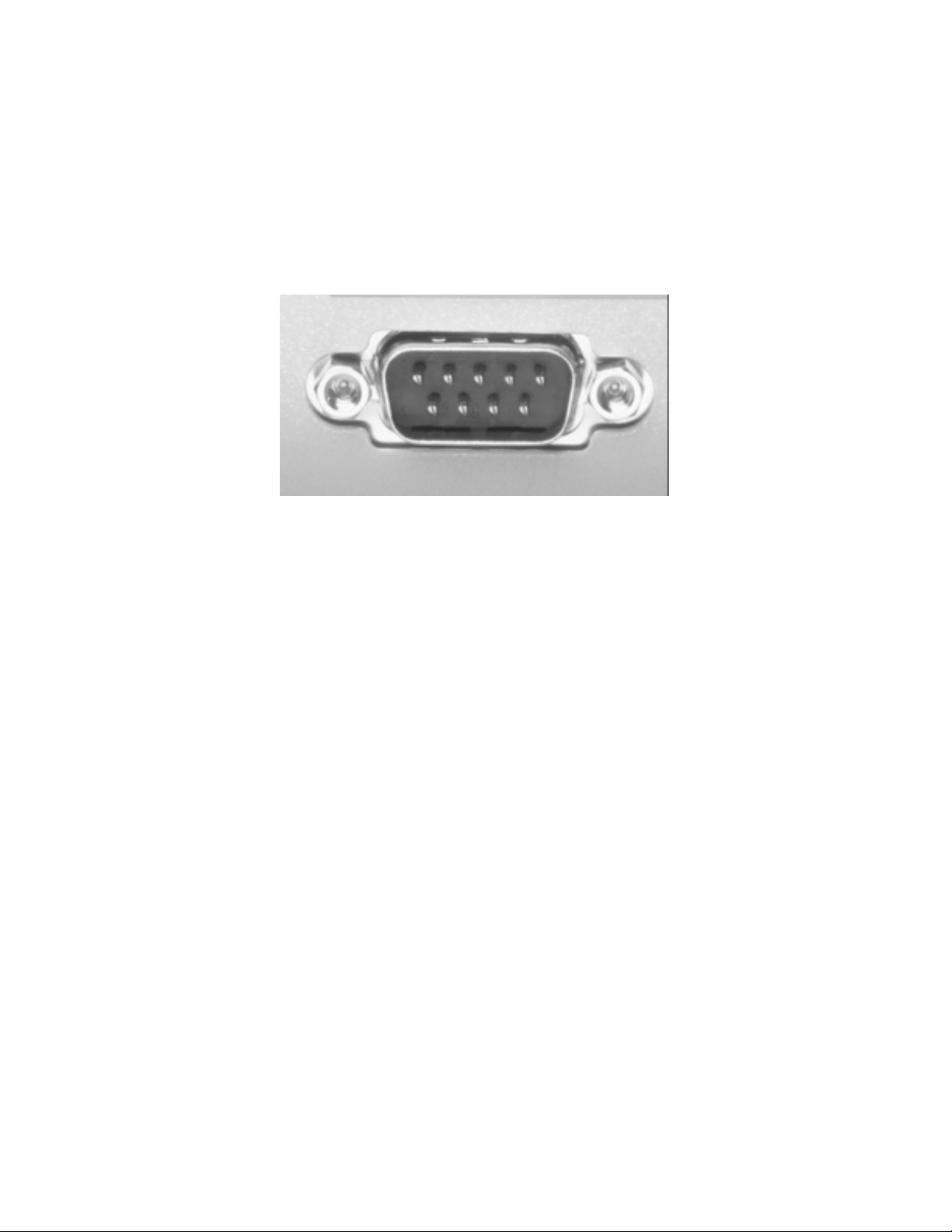
Windows XP, Windows Vista, or Windows 7. If your laptop already has a serial port (see figure
1.1 on page 2), you won’t need the USB-Serial Adapter. In this case, you can plug the null modem
cable directly from the laptop to the control. The connection is this:
Laptop ⇒ Null Modem Cable ⇒ EL6 control
Figure 1.1: Laptop Serial Port
If your laptop is not equipped with a serial port, you’ll need to use both the USB-serial adapter
and the Null Modem adapter. If you don’t use both parts, it will never work. In this case, the
connection is this:
Laptop ⇒ USB-Serial Adapter ⇒ Null Modem Cable ⇒ EL6 control
1.2 Calling for Help
Make sure you’ve checked the stupid stuff:
• Do you have the proper cabling?
• If using the USB-Serial Adapter, is the driver installed?
• Check the information area for programing errors (red circles with bombs).
B&C Technologies
440 West 11th Street
Panama City, FL 32401
(850)-249-2222
(850)-249-2226 FAX
[email protected]
www.bandctech.com
2
Page 6

Chapter 2
Guide to Successful Communication
2.1 Requirements
This section provides instructions on the EL6 Windows programing software. This section is not
a tutorial on writing wash programs, but information on transferring custom programs from a
laptop computer to the EL6 control. Please note that computer refers to your laptop and control
refers to the EL6 control on the washer-extractor. Also note that ”‘click”’ means left click and right
click means (surprise!) right click. Typically, left click performs an action or selects something,
while a right click brings up a context menu. Also note that ”‘double click”’ means a double left
click. A double right click will do nothing useful.
Requirements:
1. Windows computer running Windows 98 or higher (Windows 2000, or Windows XP. Windows Vista/7 will work if you have a compatible USB-serial adapter with proper drivers.).
2. Available serial port (or USB to Serial adapter, p/n 141-102, or Radio Shack 26-949 or similar)
3. Null modem adapter (p/n 141-100, or Radio Shack 26-264 or similar)
A Note about USB-Serial Adapters
All USB-Serial adapters are not created equally! Some simply will not work for serial
communications, which is how the EL6 ”‘talks”’ to the laptop and vice versa. The
USB-Serial adapter sold by B&C Technologies is guaranteed to be compatible with the
EL6. It has been tested and field proved for over 10 years. B&C Technologies can
make no guarantee that the USB-Serial adapter purchased from Computerz-R-Us or any
other vendor will work properly. There are literally hundreds of different USB-Serial
adapters on the market, and it is impossible to test them all. If you want the guarantee
of successful operation, purchase the USB-Serial adapter from B&C Technologies - the
price is likely less that the big box stores.
3
Page 7

2.2 Transferring from the Computer to the EL6
1. Install the EL6 Win 2 programing software, available on CD or download from the B&C
website (http://www.bandctech.com). Installing the software will also install the factory
wash programs.
2. Before plugging the adapter into your computer, install the USB to Serial Adapter software,
if required. If your computer has a serial port, you do not need the USB to Serial Adapter.
Please skip to step 4. To continue:
(a) Insert the CD that came with the adapter into your drive.
(b) Navigate to your CD drive and go to USBRS232 (Last item in the folder), then Windows,
then double click on Setup. This will install the software for the USB to Serial Adapter.
Follow the instructions to install.
3. Plug in the USB to Serial Adapter. The found new hardware dialog box will appear, and the
USB to Serial Adapter will be ready to use.
4. In order for your computer to communicate with the EL6 control, you must set up the EL6
software to communicate on the correct serial port. To determine which serial port your
computer is using:
Windows XP and earlier: Start ⇒ Control Panel ⇒ System ⇒ Hardware (tab at the top)
⇒ Device Manager. Click the ”‘+”’ next to Ports to expand the view.
Windows 7: Start ⇒ Control Panel ⇒ System and Security ⇒ Device Manager. Click the
”‘+”’ next to Ports to expand the view.
See figure 2.1 on page 5. The port used for communication is COM1. If the communication
port name doesnt show up, right click on the Communications port, then click Properties,
then the click the Port Settings tab, then click on the Advanced button. See figure 2.2 on
page 5.
The COM Port must be COM1, COM2, COM3, or COM4. Use the pull down box to change
the value of the COM Port Number to 1, 2, 3, or 4, then click OK. Do not pick a COM port
that is in use.
5. Start the EL6 Win 2 software (Start ⇒ Programs ⇒ EL6 Win 2 ⇒ EL6 Win 2). On the top
menu, click Communication, then Com Setup. The dialog box shown in figure 2.3 on page
5 appears.
Make sure the COM Port selected matches the COM port shown in the device manager. Also,
move the slide bars over so that the Send and Receive timeouts are set to 1000msec.
6. Open the EL6 Win 2 software and create/modify the wash program you wish to transfer to
the machine. Please note that programs are designed to work with particular machines. For
example, you cannot download SP-60 programs into an HP-60 or any other machine. Water
levels, speeds, and timeouts will be incorrect and may cause dangerous operation. Always
test your programs before putting them into production!
7. Press the red emergency stop button on the front of the machine to turn off power to the
control.
4
Page 8
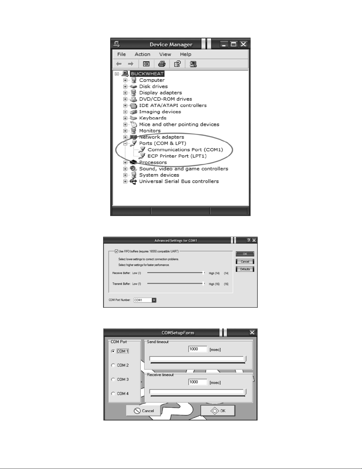
Figure 2.1: Device Manager View
Figure 2.2: Advanced Port Settings Menu
Figure 2.3: Communications Port Settings
5
Page 9

8. Connect the Null Modem cable (B&C Part number 141-100) between the EL6 and your computer (if you have a serial port) or to the USB to Serial adapter attached to your computer (if
you don’t have a serial port). If you are using the USB-Serial adapter, you MUST USE THE
NULL MODEM CABLE ALSO.
9. Open the wash program you wish to download to the EL6.
10. Release the emergency stop button. After the self test, the EL6 display will change to PROGRAM N.
11. On the EL6, press the START and RESET keys together. The EL6 display will change to n?
12. On the EL6, press 1, then 4, then 4 again. The display will show an asterisk (*) for each
number entered.
13. Timing is critical for this step. Press Enter on the EL6 keypad - the display on the EL6 will
change to RS232. As soon as the display on the EL6 changes to RS232, click the red down
arrow in the EL6 software on your computer or press Ctrl-D on your computer’s keyboard.
14. While the program is transferring to the EL6, the EL6 display will show COMPUTER ⇒ EL6
indicating that a program transfer is taking place. The laptop display will show a graphic of
a computer attached to washing machine. The lower right information will remind you to
press 144. If a red icon appears in this information box, the transfer will not start. The red
icon indicates a problem with the program, and tells you exactly what the problem is. These
problems must be corrected before the program can be saved to computer or transferred to
the EL6.
2.3 Transferring from the EL6 to the Computer
The transfer from the EL6 to the laptop is called uploading. To upload from the EL6 to the laptop:
1. Follow steps 1 through 10 in the previous section.
2. Click the red up arrow in the EL6 Software on your computer or press Ctrl-U on your computer’s keyboard. The dialog box shown in figure 2.4 on page 7 appears.
3. Ensure that the All SP, HP, SI button is selected on the left, and 24 is selected on the right.
4. Press the START and RESET keys together. The EL6 display will change to ”‘n?”’
5. Press 1, then 4, then 4 again. The display will show an asterisk (*) for each number entered.
6. Press Enter on the EL6 keypad. When the display changes to RS232, click on the OK button
in the dialog box on your laptop.
7. While the program is transferring from the EL6, the EL6 display will show EL6 ⇒ COMPUTER indicating that a program transfer is taking place. The laptop display will show a
graphic of a computer attached to washing machine. The lower right information will remind you to press 144. When the transfer is complete, you will see the program set on your
laptop display.
6
Page 10
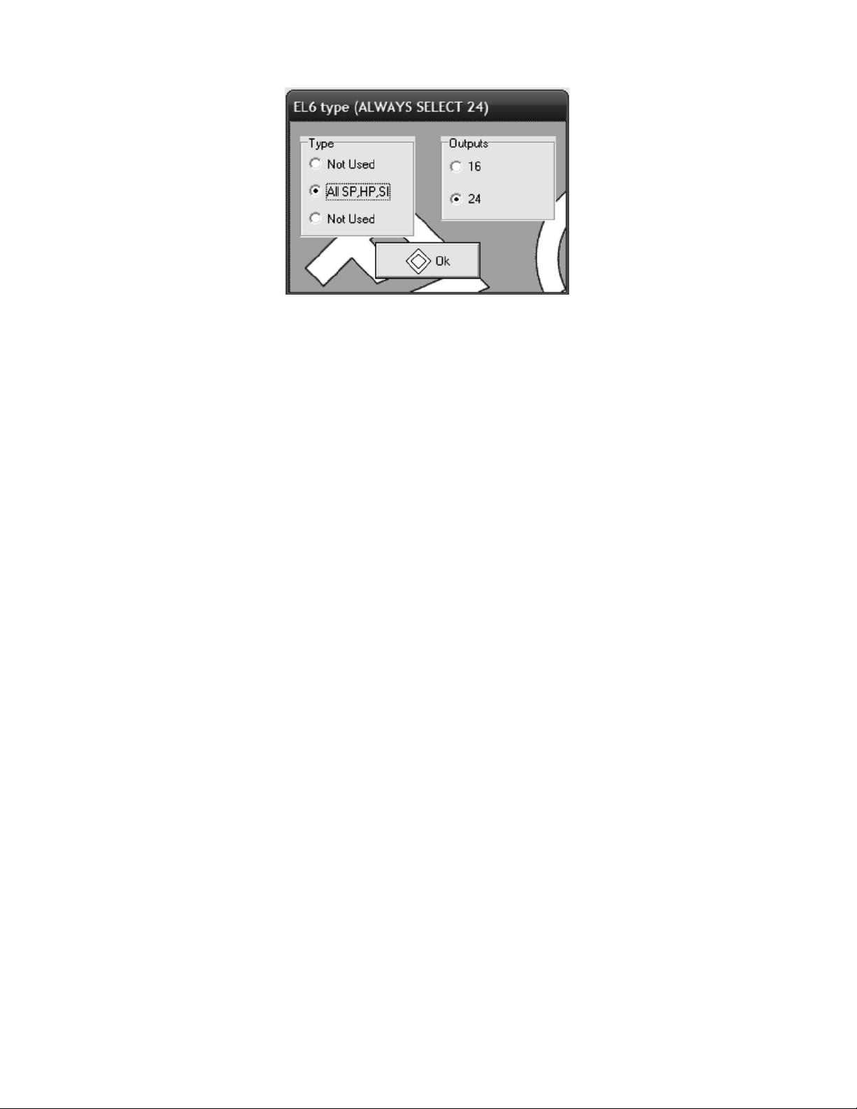
Figure 2.4: Selecting the EL6 Type
After you have uploaded the wash programs from the EL6, make sure to save the program set
before modifying them. That way there is a known good backup in case of problems. Use the File
— Save as command described previously. The easiest place to store the file is the Desktop. Of
course, the EL6 file can be placed anywhere on the computer – Don’t forget where it was saved!
2.4 Troubleshooting
1. You must use a null modem cable. An RS-232 extension cable will not work! If you are going
to purchase your cable from a computer retailer, make sure you get a NULL MODEM cable.
2. Make sure that no other software is using the COM port that you are attempting to use with
the EL6 control. If you have a PDA, or other software, such as Soap Pump control software,
you may have problems. Make sure that no programs are running that use the serial port,
except the EL6 Win 2 software.
3. If your computer has a COM port, but it doesn’t show up in the Device Manager, it may
be disabled in the BIOS of your computer to save battery power. It is beyond the scope of
this document to re-enable your serial port. Refer to your computer manual or to a qualified
computer technician.
7
Page 11

Chapter 3
EL6 Win 2 Introduction
Figure 3.1 on page 9 shows a typical screen view. The EL6 window area is divided into the
following panels:
• The section at the top left displays the list of programs and their associated cycles.
• The section below (resizable) displays the service information
• The section at the top middle displays the cycles grouped into the five categories
• The section below (resizable) displays the motor modes
• The right top section displays the list of steps associated with the cycle currently selected
(Prewash 1 in the example)
• The section below reports diagnostic information associated with the particular operation:
sending or receiving, importing, opening and closing files.
• The status bar at the bottom displays the currently selected language file.
All the areas are resizable for adapting to the editing needs and to the screen resolution. For
example if motor modes are already configured, and if it is necessary to work on cycles, area
dedicated to motor modes can be shrunk.
When one or more areas are resized the new size become the default. That means that new files or
next time the program runs, the EL6 Win 2 will recall the last used sizes.
3.1 Menu Commands
Here is the list of available menu commands:
• File — New =⇒ New file creation
• File — Open =⇒ Open a existing file
8
Page 12
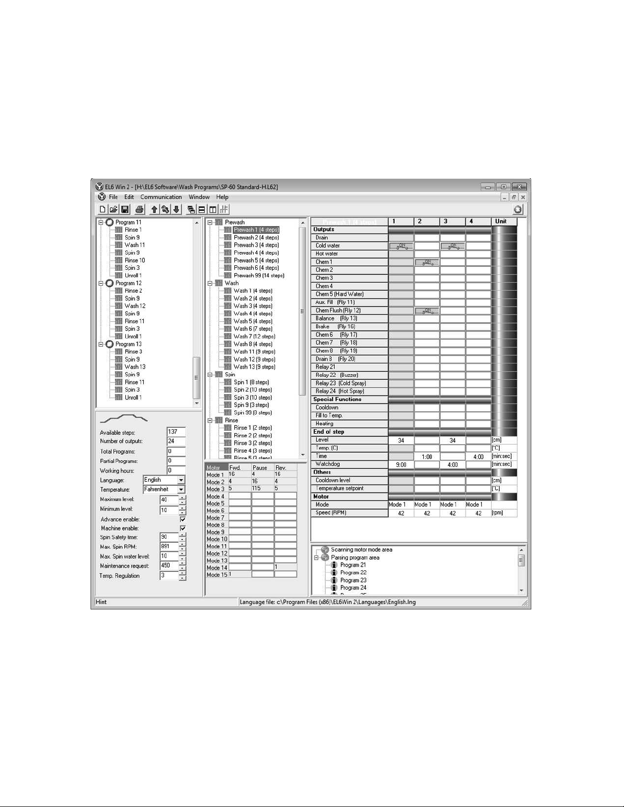
Figure 3.1: EL6 Main Program Window
9
Page 13

• File — Save =⇒ Save current window content into a file using the current file name
• File — Save as =⇒ Save current window content into a file allowing to set the name
• File — Print =⇒ Print the current window content
• File — Open language =⇒ Open a language file
• File — Import .EL6 format =⇒ Import the previous version file format
• File — Exit =⇒ Quit EL6 Win 2
• Communication — Upload =⇒ Upload configuration from a connected EL6 device
• Communication — Download =⇒ Download current file to a connected EL6 device
• Communication — Com setup =⇒ Setup for communication with an EL6 device
• Commands for windows handling
– Window — Cascade
– Window — Horizontal tile
– Window — Vertical tile
– Window — Minimize all
– Window — Arrange
• Help — About =⇒ Displays program version information
3.1.1 Additional Details About Selected Commands
File — New
This menu allows the creation of a new file. When executed, the program opens the window
shown in figure 3.2 on page 11. This is used to determine the EL6 type. Always select All SP,HP,SI
on the left, and 24 on the right. It is unlikely that this command will be used - it is very difficult to
start from scratch and build a working set of programs. It is always best to begin using the stock
programs of the machine in question. For example, if building a set of custom programs for an
SP-60, begin with the stock programs. The stock programs are automatically installed during the
EL6 Win 2 software installation and can be found in:
C : \P rogramF iles\EL6W in2\W ashP rograms\
or, for the 64 bit version of Windows:
C : \P rogramF iles(x86)\EL6W in2\W ashP rograms\
File — Import .EL6 format
This menu command allows the opening of a file created using the previous program version.
When this command is executed, the following window shown in figure 3.3 on page 11 opens.
10
Page 14
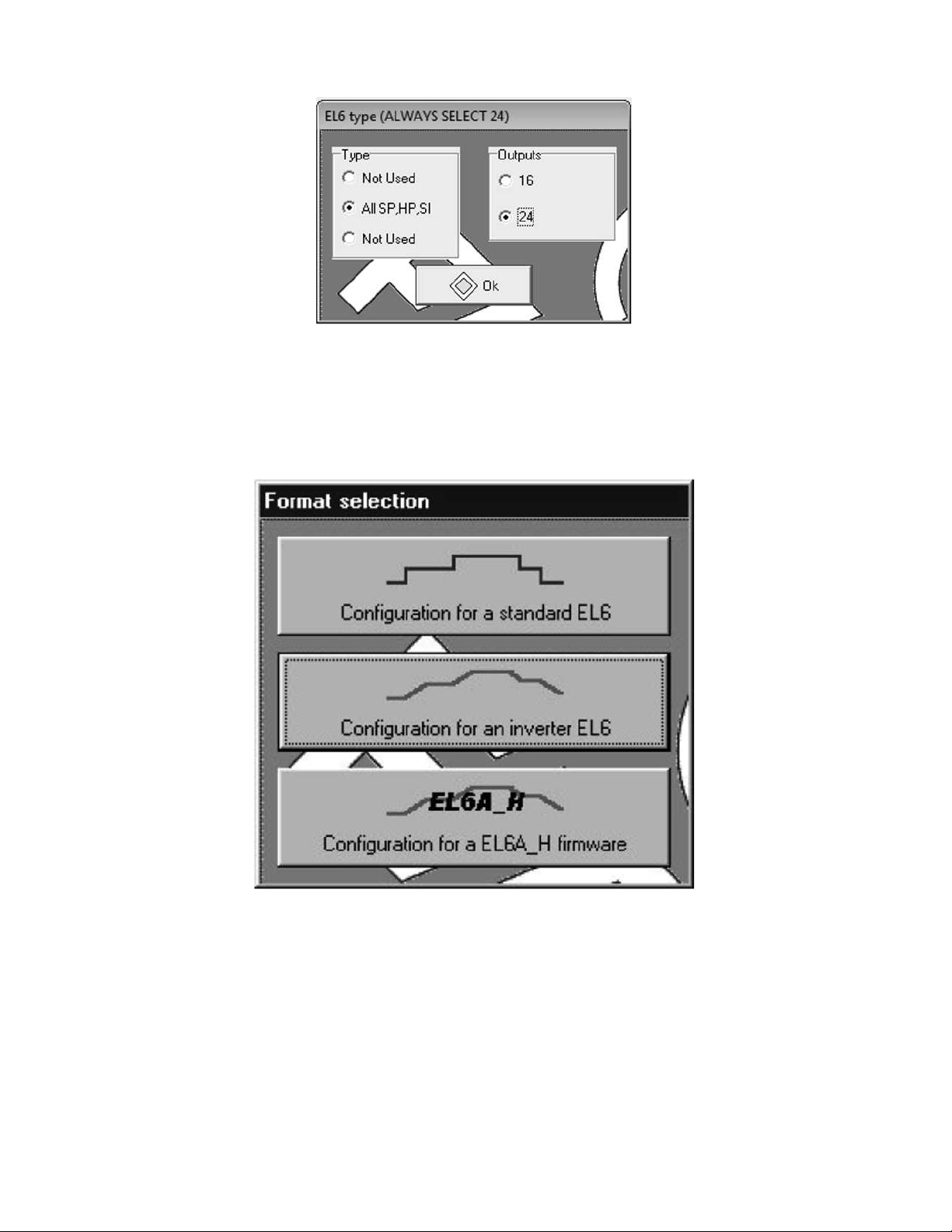
Figure 3.2: EL6 New Formula Dialog Box
Always select the middle button, EL6 Inverter for B&C Technologies machines. Once the file is
imported, it can be modified and handled normally. When saved, the file will be saved in the new
.L62 format.
Figure 3.3: Import .EL6 Format Dialog
File — Print
When this command is executed, the following window shown in figure 3.4 on page 12 opens. It
is used to select which portions of the file content are to be printed.
Help — About
When this command is executed, the following window shown in figure 3.5 on page 12 opens.
This shows the currently installed version of the EL6 Win 2 software - the current version is 2.00.24.
11
Page 15
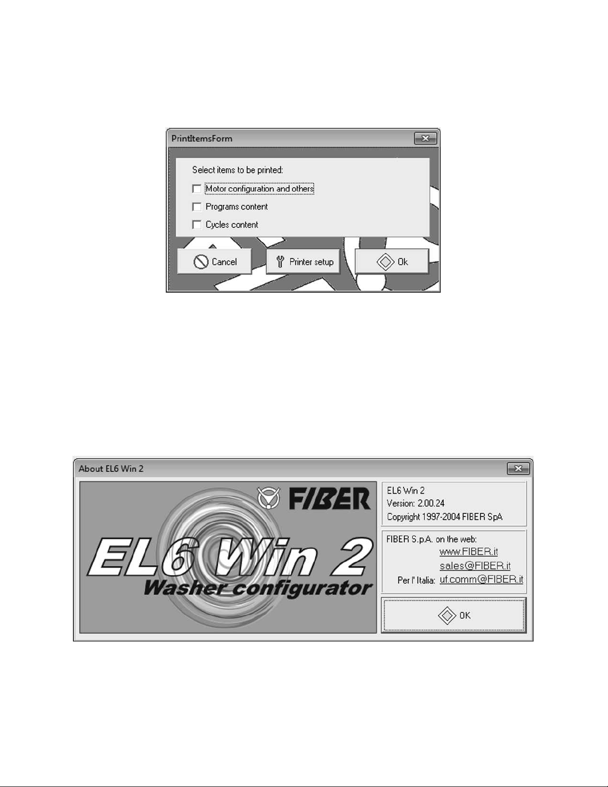
Figure 3.4: Print Dialog
Figure 3.5: EL6 Win 2 About Dialog
12
Page 16

File — Open language file
The Language File allows some customization of the EL6 Win 2 interface. The English.lng language file (the standard language file) has been modified to show the function of each relay. For
example, all B&C Washer-Extractors use Relay 13 as the balance signal relay. When looking at an
extract cycle, Relay 13 is identified as the balance relay. If programing the EL6 via the built in
keypad, Relay 13 is simply called Relay 13.
In the unlikely event that the language file does not show the extended information, the Open
Language File command allows the import of the correct Language File.
13
Page 17

Chapter 4
The Cycles Window
Remember that Programs are made up of Cycles, and Cycles are made up of Steps. The Steps are
where water valves are turned on, chemical assignments are made, etc. In order for the washer to
do anything, cycles must be programmed. Typically, most cycles are created as a wash bath - i.e.,
water is added to a certain water level (step 1), chemicals are dosed (step 2), a check is made to see
if water needs to be added (step 3), and finally, the load is agitated for some time (step 4). Refer
to figure 4.1 on page 15. Spin cycles are used for drains and extracts. Spin 9 is the drain cycle (it
contains no extract, only distribution speed). Spin 1, Spin 2, and Spin 3 are extracts (Low, Medium,
and High speed respectively).
4.1 Cycle Types
The EL6 has 5 different cycle types in order to better define a wash program. These types are
Prewash, Wash, Rinse, Spin, and Unroll.
4.1.1 Prewash, Wash, Rinse Cycles
These cycles are bath cycles, and can be used interchangeably. Typically, these cycles would contain the steps necessary to create a bath: Fill to a level, dose chemicals, Top off to make sure level
is maintained, agitate the load for some time. It is possible to insert steps to dose additional chemicals, add a drain step, fill step, and agitate step to insert a cheater rinse, or do whatever needs to
be done for the particular wash process. The EL6 is very flexible. The EL6 Stock Program Listing
has details on the standard cycles included with the machine. All cycles can be modified at will.
A Note about Prewash 99: The Prewash 99 cycle is a diagnostic cycle which goes
through each output of the control. It is very useful when troubleshooting the machine when service is required. Unless a very complicated set of wash programs are
being built, there will be plenty of left over steps and it is not necessary to delete this
cycle.
14
Page 18
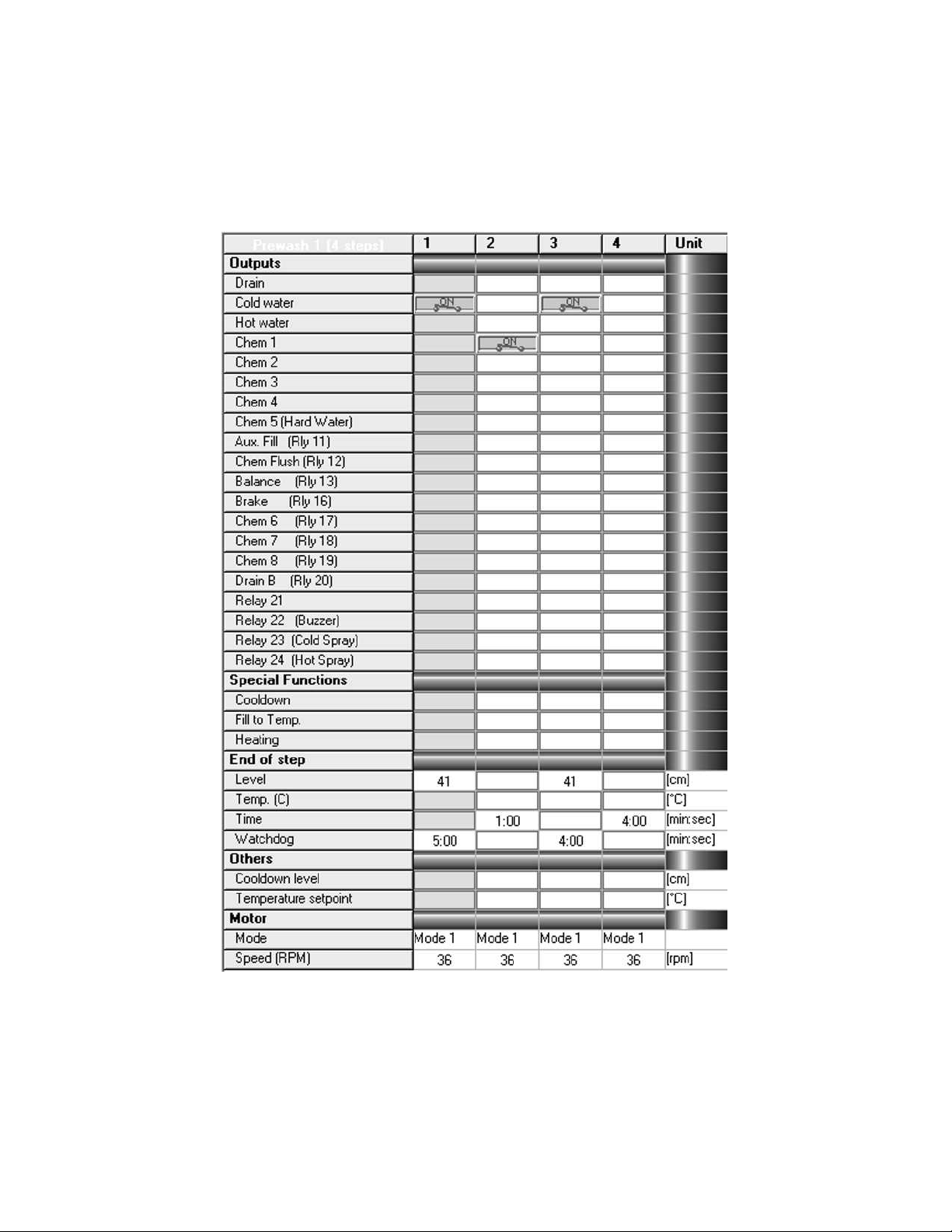
Figure 4.1: EL6 Cycle Window
15
Page 19

4.1.2 Compound Rinses
Rinses and other cycles may be combined into a larger single cycle containing many steps. Rinse
10, 11, 12, and 13 as shown in the stock programs are examples of this idea. Refer to figure 4.2
on page 17 for details. By combining several rinses into one cycle, it is possible to do more baths
under the 15 cycles per program limitation. For example, a typical wash program might look like
this:
Program 1
• Prewash 1
• Spin 9 (drain)
• Wash 1
• Spin 9 (drain)
• Rinse 1
• Spin 9 (drain)
• Rinse 1
• Spin 9 (drain)
• Rinse 3
• Spin 3 (extract)
• Unroll 1
This simple wash program uses 11 cycles. By using a compound rinse the number of the cycles in
the program can be reduced to:
Program 1
• Prewash 1
• Spin 9 (drain)
• Wash 1
• Spin 9 (drain)
• Rinse 11
• Spin 3 (extract)
• Unroll 1
16
Page 20
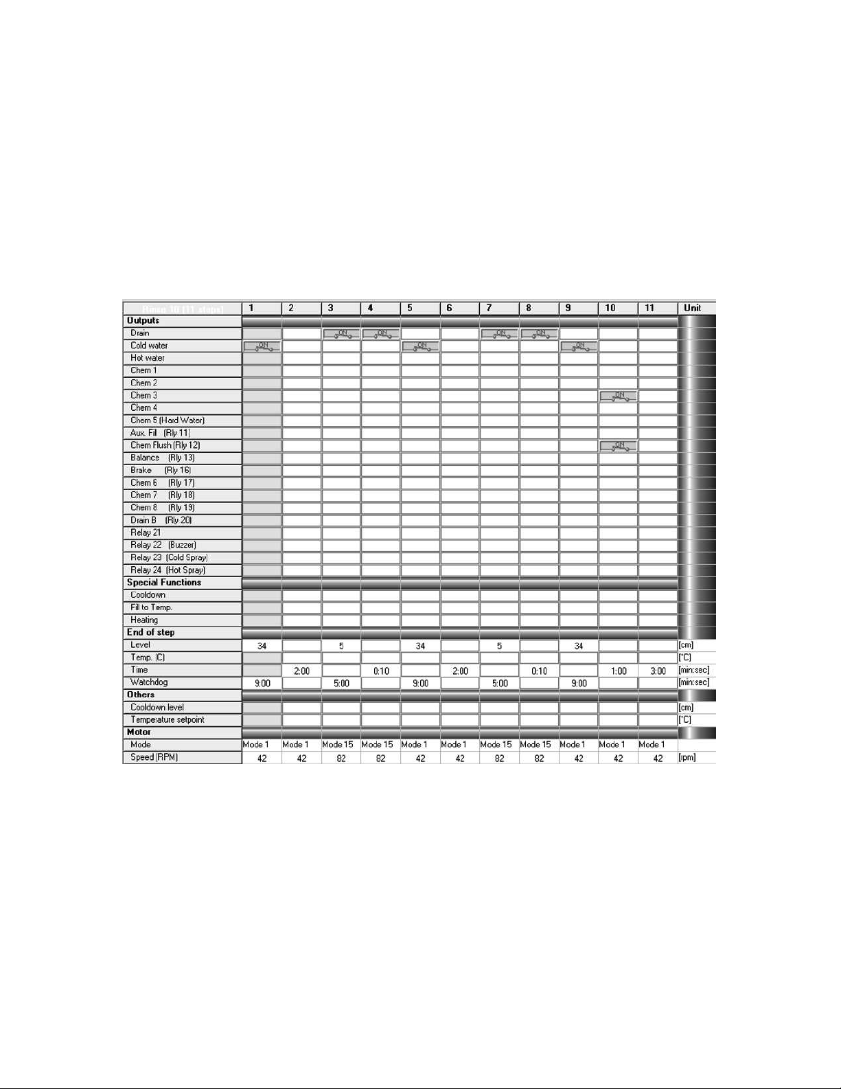
Figure 4.2: Compound Rinse Example
17
Page 21

Program 1 now contains only 7 cycles, leaving room for plenty of customization in the wash process.
A Note about modifying Bath cycles: Modifying a cycle changes that cycle in whatever
program that cycle is used. For example, if Wash 11 is used in Program 1 and Program
2, changes to Wash 11 would affect both Program 1 and Program 2. Use this feature to
advantage! Much time can be saved through similarities in wash programs.
4.1.3 Spin Cycles
The spin cycles are used for drains and extracts:
• Spin 1 — 30 second intermediate spin
• Spin 2 — 5 minute medium speed spin
• Spin 3 — 5 minute high speed spin
• Spin 9 — Drain with no spin
A Note about modifying Spins: The EL6 is an incredibly flexible control – so flexible that it is possible to create cycles that don’t work! The most common difficulty is
with the spin cycles. By all means, use the existing spins and do not modify them. If a
change is needed, the best course of action is to only modify the time or the RPM in the
maximum RPM step, programmed for 4:30. This is the only step that affects the duration and force of the extract. The remaining steps control the ramp up to distribution
speed, the balance step, and finally after the extract, the braking routine. Altering any
of these steps will result in poor results and likely no extract at all.
4.1.4 Unroll Cycles
The Unroll cycles in the factory EL6 programs are used for redistributing the load in the event of
an unbalance (Unroll 99) and as a shakeout routine at the end of the program (Unroll 1). Deletion of the Unroll 99 will remove the balance retry routine, and upon failure of balance, program
termination (No balance retries).
4.2 Reserved Cycles
4.2.1 Unroll 99 - Spin retry routine
On an out of balance condition, the EL6 will jump from the programmed spin to the Unroll 99
cycle. After Unroll 99 has completed, the EL6 starts back at the beginning of the spin cycle where
18
Page 22

the imbalance occurred. The EL6 will retry 3 times before terminating the program. This cycle
should not be added to any program.
4.2.2 Spin 9 - Drain with no spin
Typically, a drain will follow a bath in a standard wash formula (no surprise!). The easiest way to
achieve this is by using the already programmed Spin 9. Adding drain steps in each bath would
waste many steps over simply using the Spin 9 routine (only 2 steps). In fact, this is a major
strength of the EL6 – the ability to use a similar function over and over without reprograming is a
major time saver and makes it very easy to maintain the programs in the future.
Note: NEVER USE 00 for a cycle number. EL6 Win will accept the data, but the
programs will not execute properly.
4.3 Adding a Cycle
To add a cycle, simply click the header of the cycle type you wish to add, right click, and on the
sub-menu that appears, select New Cycle. Alternatively, press the Insert key on the computer
keyboard.
Example
Adding a new Prewash Cycle:
1. Click on Prewash in the cycles window (Prewash is now highlighted).
2. Right click on Prewash – the sub-menu appears.
3. Click New Cycle.
4. A new cycle appears at the bottom of the Prewash cycles list, with the next available lowest
number.
4.4 Deleting a Cycle
To delete a cycle, click the cycle to select it. Pressing the delete key on the laptop keyboard or right
click, then selecting Delete from the sub-menu will delete the cycle.
4.5 Copy and Paste a Cycle
To copy a particular cycle, first select the cycle to copy so that it is highlighted. Right click on the
selected cycle, then click Copy Cycle on the sub-menu. The cycle is now copied to the clipboard
19
Page 23
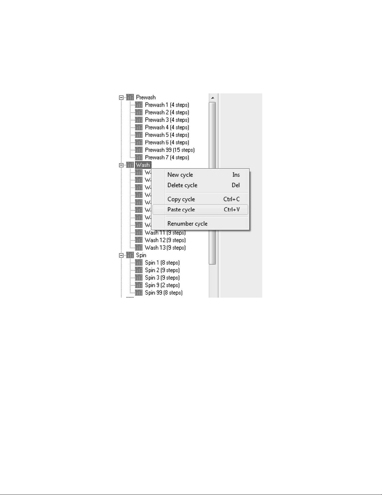
and can be pasted as a new cycle. To paste the cycle, select the cycle group header in which the
cycle is to be pasted. For example, if the cycle will be a Wash cycle, click on and select the Wash
header, located above all the other wash cycles. See figure 4.3 on page 20. Notice that the header,
Wash, is highlighted. Now right click on Wash and click Paste Cycle in the sub-menu. The pasted
cycle will appear as the next available cycle number at the bottom of the list of Wash cycles.
Figure 4.3: Pasting a cycle
Note: A cycle can be copied from one cycle type and pasted into another, i.e. copied
from a Prewash cycle and pasted into a Wash cycle.
4.6 Renumbering a Cycle
Cycles can be renumbered for convenience easily. Simply select the cycle to be renumbered in the
list of cycles, right click on the cycle, then select Renumber cycle from the sub-menu. Make sure
to choose a cycle number that is not in use. Any value from 1 to 99 may be selected and used. If
the cycle is already used in a program, be sure to delete the old cycle and replace it with the newly
renumbered cycle.
20
Page 24

4.7 Working with Steps
The steps are the building blocks used to create a wash cycle. Each cycle can contain up to 100 steps
but remember that there are only 400 total steps allowed in total. The cycles window is shown in
figure 4.1 on page 15. Everything that happens during the wash cycle is controlled discreetly by
a step – one function at a time is performed (Fill ⇒ Chemical Dose ⇒ Top off ⇒ Agitate). Here’s
what is happening in the example cycle, Prewash 1, a bath (Drains and Spins are handled using
different cycles).
• Step 1:
The cold water output is energized, with an end step condition of 41cm, a 5 minute watchdog
timer, and a speed of 36 RPM using motor mode 1.
Step 1 is the fill step for this bath. The cold water valve will remain energized until the
programmed water level is reached. Alternatively, if the watchdog time expires before level
is reached, the EL6 will display a WTD TIME EXP alarm, indicating that the machine did
not reach level. During the fill, the wash cylinder will rotate at 36 RPM using motor mode 1
(16 seconds forward, 4 second pause, 16 seconds reverse). As soon as water level is reached,
Step 1 is over, and Step 2 begins.
• Step 2:
The chemical 1 output is energized, with an end step condition of 1 minute, and a speed of
36 RPM using motor mode 1.
Step 2 is the chemical dosing step. The chemical signal selected (Chemical 1) remains on for
1 minute. During this time, the wash cylinder will rotate at 36 RPM using motor mode 1 (16
seconds forward, 4 second pause, 16 seconds reverse). As soon as the time elapses, Step 2 is
over, and Step 3 begins.
• Step 3:
The cold water output is energized, with an end step condition of 41cm, a 4 minute watchdog
timer, and a speed of 36 RPM using motor mode 1.
Step 3 is the top off step. The cold water valve will remain energized until the programmed
water level is reached. Alternatively, if the watchdog time expires before level is reached, the
EL6 will display a WTD TIME EXP alarm, indicating that the machine did not reach level.
During the fill, the wash cylinder will rotate at 36 RPM using motor mode 1 (16 seconds
forward, 4 second pause, 16 seconds reverse). Typically, this step is skipped as the water level
doesn’t typically drop enough to trigger the fill valve. If the goods are unusually absorbent,
this step can top off the water level. As soon as water level is reached, Step 3 is over, and
Step 4 begins.
• Step 4:
No outputs are energized, with an end step condition of 4 minutes, and a speed of 36 RPM
using motor mode 1.
Step 4 is the agitation step. No outputs are turned on, so the cylinder rotates at 36 RPM using
motor mode 1 (16 seconds forward, 4 second pause, 16 seconds reverse) for the duration of
the step. Once step 4 is over, the EL6 moves to the next programmed cycle – typically a drain
(Spin 9).
21
Page 25

Each step is split into 5 segments:
1. Outputs
2. Special Functions
3. End of Step
4. Others
5. Motor
4.7.1 Outputs
The outputs are fairly self explanatory. When a particular output is turned on, that function is
activated. Each relay output can be turned off or on by double clicking in the cell, or by pressing
the spacebar when the cell is highlighted.
4.7.2 Special Functions
Heating, Fill to temperature, and Cooldown are controlled by this section. Double clicking a function enables that function. When activated, each item will open a dialog box which asks for parameters necessary for the activation of the function.
4.7.3 End of Step
Each step must have an end step condition – this is the condition to be met, indicating that the step
is complete. Level and Temperature require a Watchdog time to be entered (typically 9 minutes for
Level and 15 minutes for Temperature). The Time end step condition will automatically end when
the time elapses, eliminating the need for a Watchdog. To edit or enable an end of step condition,
double click. A dialog box will appear, allowing to to change or enter a value.
4.7.4 Others
The Cooldown level and Temperature setpoint fields are indicators only - these fields will be blank
unless one selects the Cooldown function or the Heating function.
4.7.5 Motor
The motor segment indicates which motor profile and RPM (speed) will be used. Refer to the
water level chart, figure 4.4 on page 23 and the RPM chart shown in table 4.1 on page 24 for
details on the correct setting for the particular machine being programmed. Double clicking the
field will cause a dialog box to appear so that the correct value can be chosen.
22
Page 26
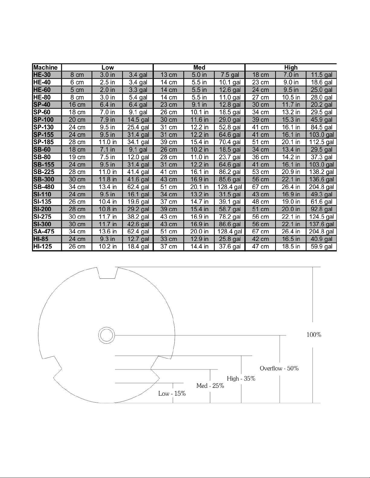
Figure 4.4: Water Level Guide
23
Page 27

Table 4.1: EL6 Programming - Speed Guide
Machine Wash RPM 100G 150G 200G 300G
HI-85 40 443 542 626 x
HI-125 37 410 502 579 x
HP-60 42 476 583 673 823
SA-475 30 332 406 469 574
SP-40 46 513 628 726 889
SP-60 42 476 583 673 824
SP-100 40 441 540 624 764
SP-130 36 410 502 579 709
SP-155 36 405 496 573 701
SP-185 35 392 481 555 680
SB-60 42 476 583 673 823
SB-80 42 476 583 673 823
SB-155 36 409 501 579 709
SB-225 36 409 501 579 709
SB-300 35 386 473 546 669
SB-485 32 358 439 506 619
SI-110 39 436 534 617 756
SI-135 36 405 496 573 701
SI-200 35 391 479 553 678
SI-275 33 368 451 521 638
SI-300 33 368 451 521 638
24
Page 28
4.8 Inserting a New Step
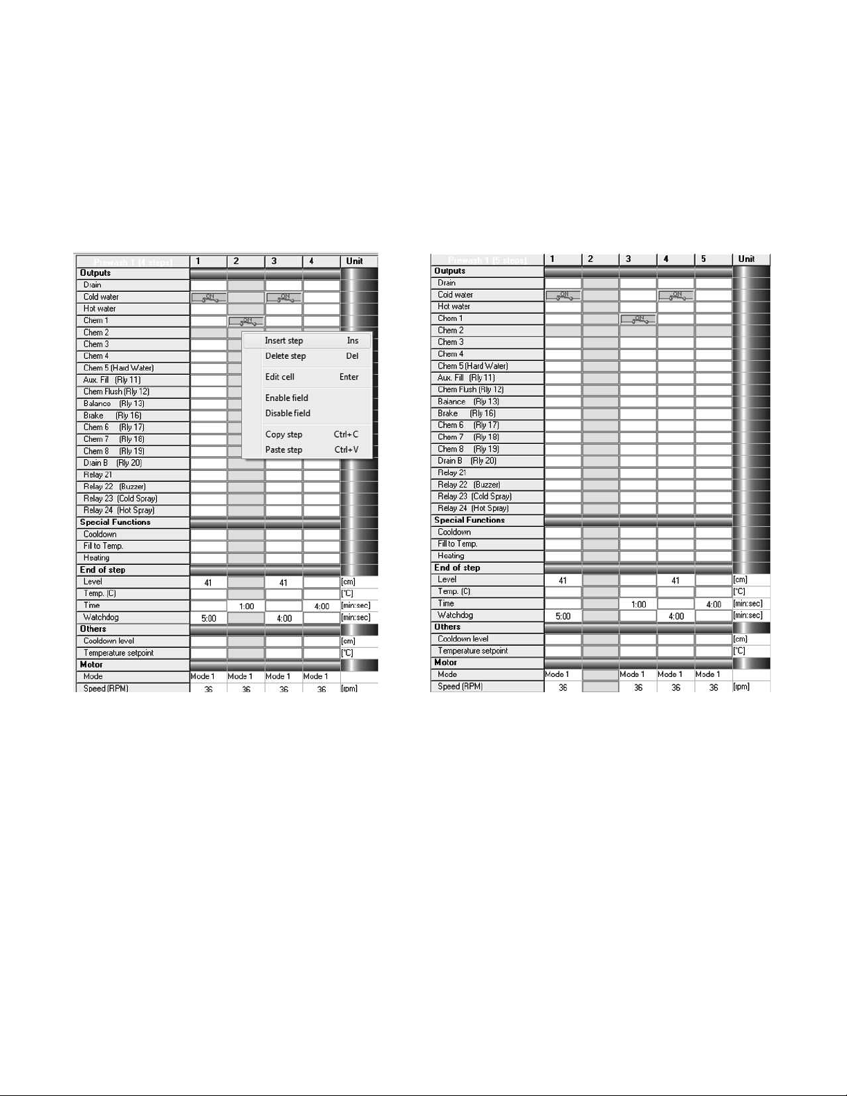
A new step is created by selecting an existing step, then right clicking the step. When the submenu appears, click Insert step or press the Insert key on the laptop keyboard. Refer to figure 4.5
on page 25. A new blank step is now inserted. Notice that all existing steps shift one column to the
right and that the new step has replaced the previously highlighted step (Step 2 was highlighted,
and now the new step is Step 2 and the previous Step 2 is now Step 3).
Figure 4.5: Inserting a new step
4.9 Deleting a Step
To delete a step, select the step to delete – the column will be highlighted in yellow. Right click the
step and select Delete step or press the delete key on the laptop keyboard. Be careful! There is no
undo!
4.10 Copy/Paste a Step
To copy a step, select it by clicking on it – the column will be highlighted in yellow. Right click
the step and select Copy step. Now select where the step needs to go, either in the current cycle
25
Page 29
or another cycle in the program group. Right click, and select Paste step from the sub-menu. Just
as with the Insert Step function, all existing steps shift one column to the right and that the pasted
step has replaced the previously highlighted step.
4.11 Enabling/Disabling Cells
In order to change the function of a step type, the existing end step function must be disabled
before the new condition can be enabled. The EL6 allows only one end step condition per step.
To disable a field, click the cell to select it. Then right click the cell and select Disable field from
the sub-menu. Now a different end step condition can be selected. If moving from a level or
temperature based step to a timed step, the watchdog timer must also be disabled. The motor
mode and RPM fields can also be disabled if no cylinder rotation is desired (Still fill for example).
4.12 Special Functions
4.12.1 Cooldown
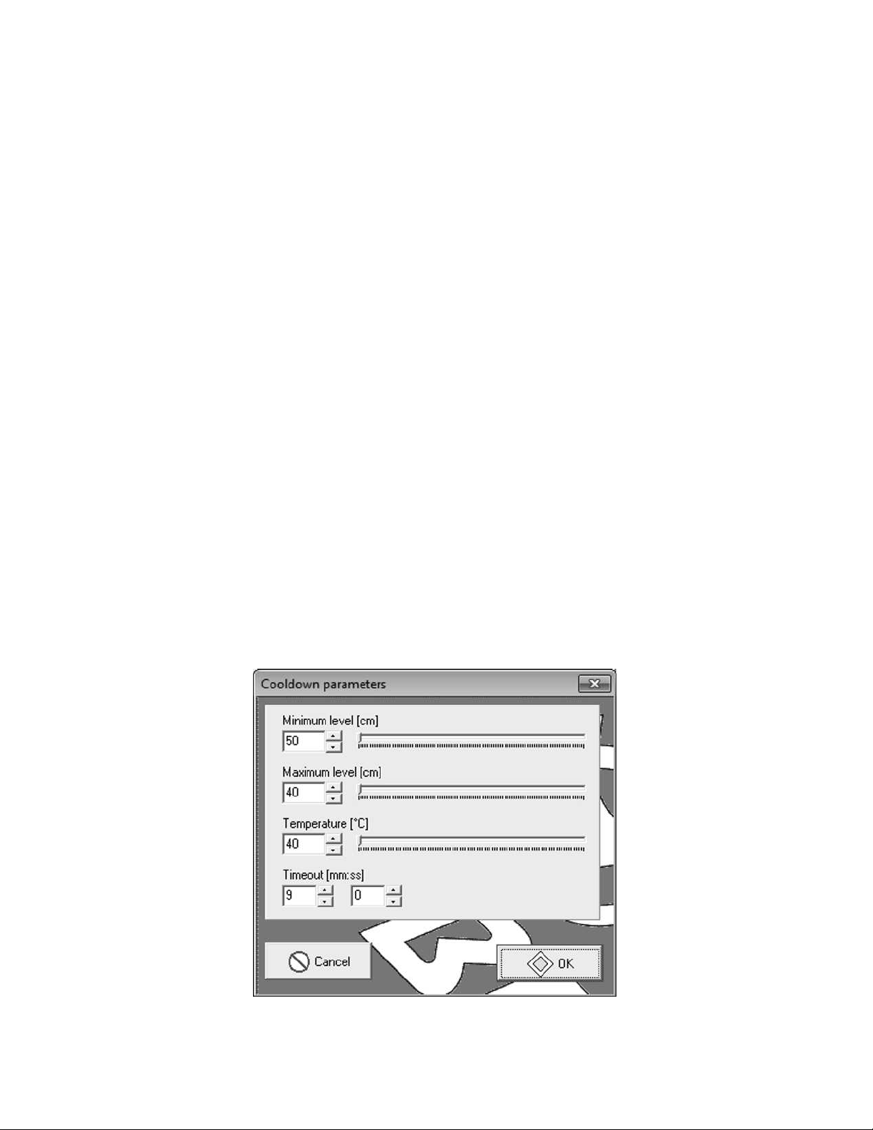
The cooldown function can be used to cool the laundered goods to a particular temperature. Enabling the cooldown function will display the sub-menu shown in figure 4.6 on page 26. Enter the
minimum water level (in cm of water), the maximum water level (in cm of water), the desired temperature (in degrees Celsius), and the allowed time. The EL6 will alternate between draining and
filling of the machine in order to reach the desired temperature while maintaining the minimum
and maximum level parameters given a particular time.
Figure 4.6: Cooldown Dialog
26
Page 30
4.12.2 Fill to Temperature
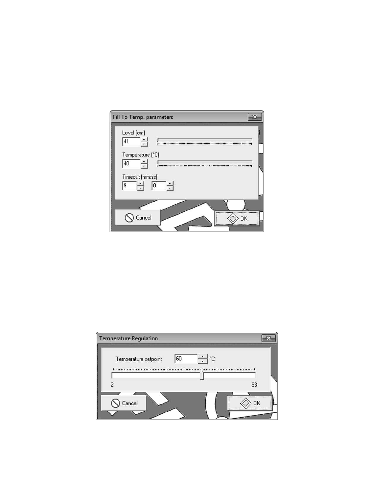
The Fill to Temperature function is used to fill the machine to a temperature between the incoming
cold and hot water supply lines. Enabling the Fill to Temperature function will display the submenu shown in figure 4.7 on page 27. Enter the water level (in cm of water), desired temperature
(in degrees Celsius), and the allowed time. The EL6 will modulate the cold water and hot water
valves to maintain the programmed temperature to the given level in the alloted time.
Figure 4.7: Fill to Temperature Dialog
4.12.3 Heating
The heating function controls the auxiliary heating system optionally installed (typically steam or
electric heating). Enter the desired temperature (in degrees Celsius). The EL6 will regulate the
temperature within 3 degrees Celsius (adjustable – see the maintenance functions section on page
35). Enabling the Heating function will display the sub-menu shown in figure 4.8 on page 27.
Figure 4.8: Heating Dialog
27
Page 31

4.13 Creating a Heat Cycle
Any cycle can be converted to a heating cycle by inserting a step after the fill, and setting the end
step condition to a temperature (See Step 2 in figure 4.9 on page 29).
Step 1 - Fill to a water level with hot water. Heat is on, and will engage when a minimum water
level is met. Watchdog timer of 5:00 allows time to fill before an alarm is generated. Step 1 ends
when the water level is reached.
Step 2 - Heat output is on. Watchdog timer of 15:00 allows time to heat to the required temperature
before an alarm is generated. Step 2 ends when the target temperature is reached.
Step 3 - Heat output is on, Chemical 1 output is on. Step 3 ends when a time of 1:00 elapses.
Step 4 - Top off step, same outputs as step 1.
Step 5 - Heat output is on in order to regulate temperature during the agitation phase. Step 5 and
the entire cycle are complete when a time of 7:00 elapses.
28
Page 32
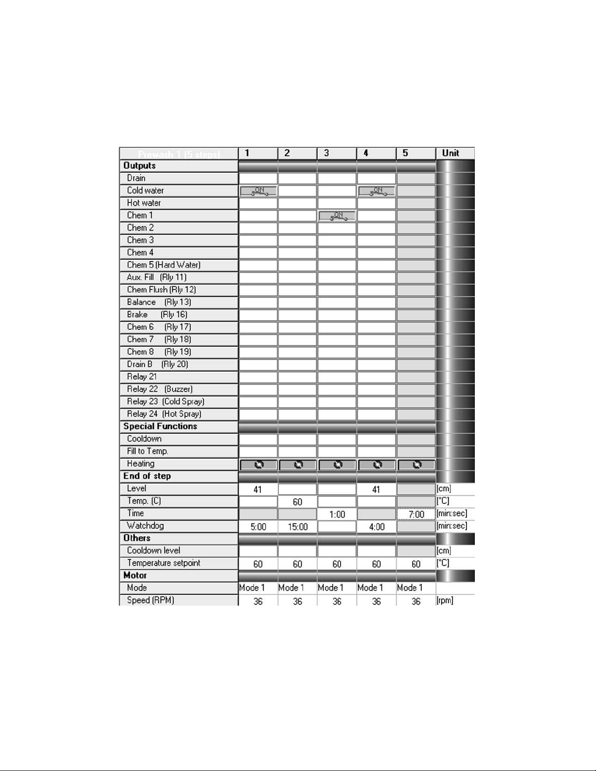
Figure 4.9: Typical Heat Cycle
29
Page 33
Chapter 5
Motor Modes
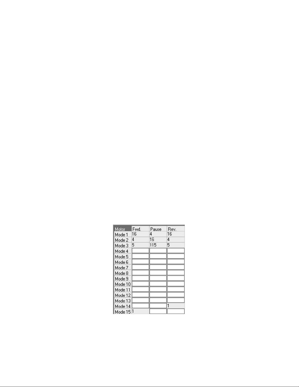
Motor Modes are used to set the agitation profile for each step. There are 5 stock motor modes
used:
• Mode 1 – Standard wash agitation: 16 seconds forward, 4 seconds pause, 16 seconds reverse
• Mode 2 – Gentle wash agitation: 4 seconds forward, 16 seconds pause, 4 seconds reverse
• Mode 3 – Soak agitation: 5 seconds forward, 115 seconds pause, 5 seconds reverse
• Mode 14 – Reverse only: Used in the rebalancing function after an unbalance condition.
• Mode 15 – Forward only: Used in extract cycles
Figure 5.1: Motor Mode Area
To customize or add a new motor mode, simply double click in the field you wish to adjust. Refer
to figure 5.1 on page 30. When the sub-menu appears, change the seconds value to fit the process.
Any value between 1 and 240 seconds may be entered.
30
Page 34

Chapter 6
Creating/Modifying/Deleting Programs
6.1 Creating a New Program
Once a library of cycles is in place, a new wash program may be created. To create a new wash
program, click on any existing program, then right click that program and select Insert program
from the sub-menu. Alternatively, press the insert key on the laptop keyboard. A new blank
program is created at the end of the existing program list. The new program will be numbered with
the next available unused number. If adding a new program to the stock programs, Program 1 will
be found at the bottom of the program list in the programs window on the upper left of the EL6
Win 2 main window. Cycles may be added to this new program by the ”‘drag and drop”’ method:
1. Click and hold the desired first cycle in the new program.
2. Drag the mouse over to the new program (continue holding in the left mouse button).
3. Release the left mouse button when the dragged cycle is on top of the new program (The
program name will be highlighted).
Remember that an EL6 program can contain a maximum of 15 cycles. Unfortunately,
the EL6 Win 2 software doesn’t do a great job of monitoring this limitation. Adding
more than 15 cycles to a program will lead to program corruption and wash program
misbehavior.
This dropped cycle becomes the first cycle in the new program. Adding additional cycles to the
program is the exact same procedure with one exception – when the next cycle is dragged over,
drop it on the last cycle added to the program to add it to the bottom of the list. Otherwise, the
new cycle will land directly below the cycle is is dropped onto. This is useful if a cycle or cycles
need to be inserted into an existing wash program.
31
Page 35
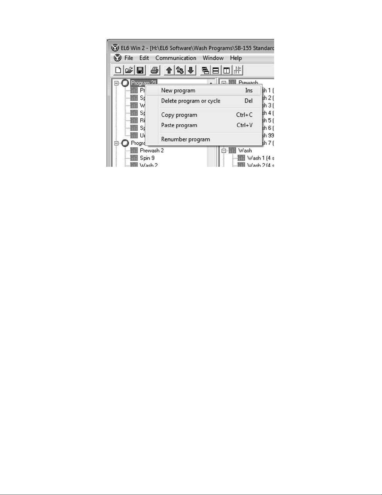
Figure 6.1: Creating a New Wash Program
6.2 Modifying a Program
As mentioned in the previous section, wash cycles may be added to existing programs through
dragging and dropping. To remove a cycle from a program, click on the cycle to be removed so
that it is selected. Right click the cycle, then click Delete program or cycle, or press the Delete key
on the laptop keyboard. Make sure the desired cycle is selected before deletion – there is no undo!
6.3 Deleting a Program
Deleting a program is similar to deleting a cycle from a program. Select the program to be deleted
by clicking on it. Right click the program, then select Delete program or cycle, or press the Delete
key on the laptop keyboard. Make sure the desired program is selected before deletion – there is
no undo!
32
Page 36
Chapter 7
Information Window
The information window is located at the bottom right of the EL6 Win 2 window. During file save
or file open operations, the EL6 Win 2 software error checks the file. During this procedure, the
information window will change and give details about the progress of this error check.
Each node in the tree is represented by an icon:
– Action in progress
Includes:
• Parsing program area
• Analysis of program contents
• Scanning motor modes
• Analysis of motor modes
• Data upload or download
• File save
• Cycle tree scan
– Details about an action in progress
Includes:
• Program content analysis
• Adding a new cycle
• Handshaking in progress
33
Page 37
• Sending data
• Receiving data
– Warning message
Includes:
• Reminder to put the EL6 in communication mode - function 144
– Error message which stops an action in progress.
Includes:
• No programs configured
• Program empty
• Non-existing cycle
• Motor mode wrong
• Trouble opening file
• Empty cycle
• Too many steps
• Step contains no end step value
• Step uses a motor mode that isn’t configured
• Step has no watchdog time configured
• Cannot handshake with EL6
• Communication timeout expired
• Error sending data
• Error receiving data
• Data not complete
If an error occurs and the (bomb) icon is displayed, the information window automatically
resizes so that the user is better able to see the fault.
34
Page 38
Chapter 8
Maintenance Functions
The maintenance functions are located in the maintenance area, located directly below the program
window on the lower left of the EL6 Win 2 window. Refer to 8.1 on page 35 for details. If the items
in the maintenance area are hidden, hover the mouse on the bar just over the red ”‘squiggly”’ line
in the lower left of the window. The mouse cursor will change, and the bar can be dragged up,
revealing the maintenance area.
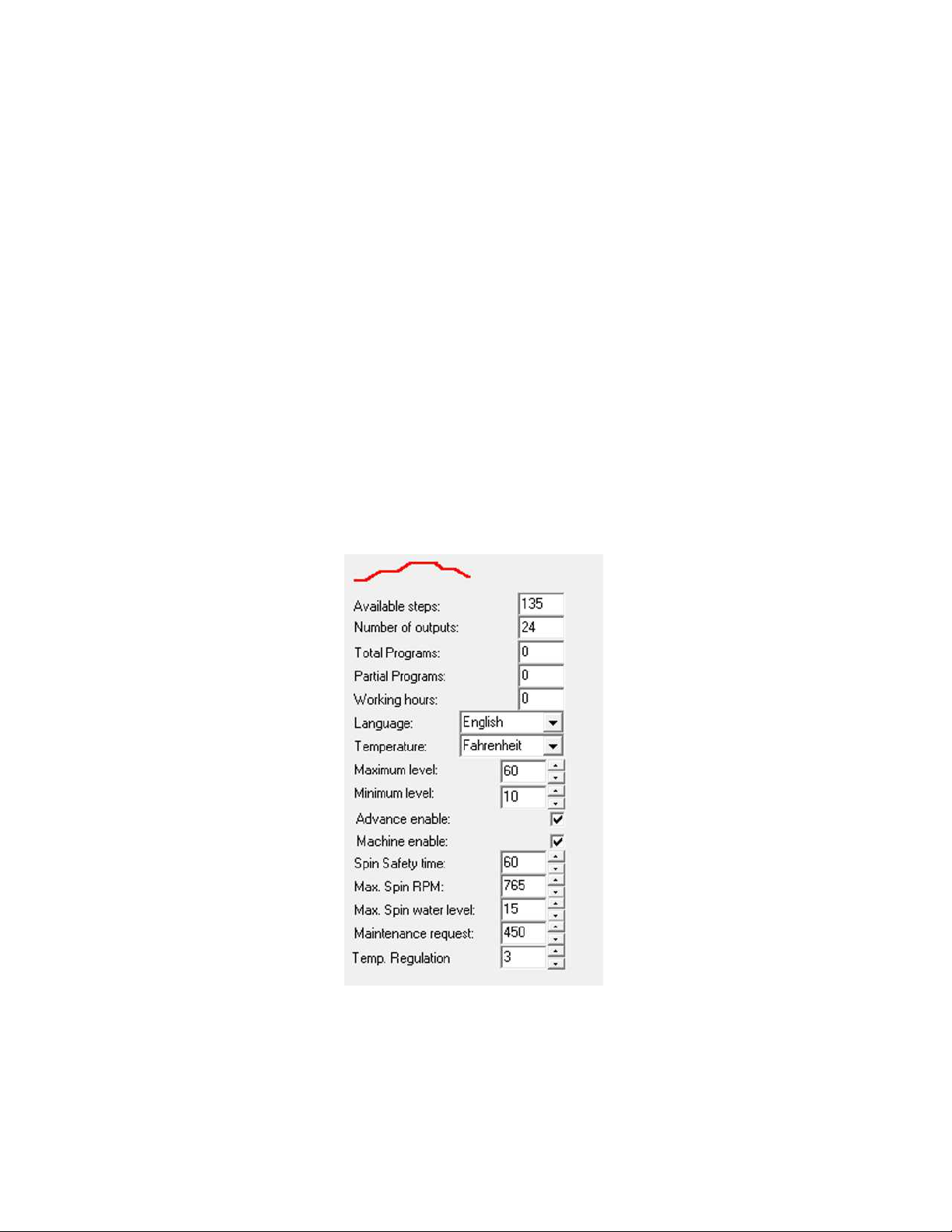
Figure 8.1: Maintenance Area
The items in the maintenance area are:
• Available Steps
Displays the number of steps left in memory allowed to be used. Read only.
35
Page 39

• Number of outputs
Displays the EL6 configuration. Should ALWAYS say 24. Anything else and your programs
WILL BE CORRUPTED. Recovery is possible, but embarrassing for the poor soul that makes
this error. Read only.
• Total Programs
The total number of programs this EL6 control has executed, not including partial programs.
Take care when transferring programs to a machine in use. If the stock programs are transferred to the machine, this counter will be overwritten. If making changes, it is best practice
to transfer the program set from the machine to the laptop, make the appropriate changes,
and finally transfer the programs back to the control. This keeps all counters in order in the
event that the owner/operator is making use of the program tracking features of the EL6.
Read only.
• Partial Programs
The total number of interrupted programs, caused by stopping the program before completion or possibly an out of balance condition. Read only.
• Working hours
The number of hours the control has spent executing wash programs. Does not include idle
time. Read only.
• Language
Selects from amongst 5 the languages the EL6 can display.
• Temperature
Select to display temperature in degrees Fahrenheit or degrees Celsius. Note: programing is
still done in degrees Celsius.
• Maximum level
Do not change - overflow and water waste will occur if levels too high for the machine are
programmed.
• Minimum level
Should never need changing. Leave at 10cm.
• Advance enable
Unchecking the box disables the advance button on the EL6 keypad.
• Machine enable
Unchecking the box will cause the EL6 to display an exclamation point (!) upon power cycle.
Very likely to confuse the operator and/or make the operator think the control is damaged.
• Spin safety time
Do not adjust! Really. Do not adjust!
36
Page 40

• Max Spin RPM
Sets the scaling so that the control can properly control the inverter drive. Adjustment of this
parameter will very likely cause the machine to never extract. Other speeds will be off, but
the dead giveaway is no extract. Do not adjust.
• Max Spin water level
Should never need adjustment. Setting this lower than 10cm can cause the machine not to
spin. Setting it to 0cm will just about guarantee that the machine won’t spin.
• Maintenance request
Sets the number of programs needed to trigger the maintenance alarm. Typically 450 programs is about a monthly reminder.
• Temperature regulation
Controls the amount the temperature can drop before the heat is turned back on. 3 degrees
Celsius is typical.
37
Page 41

Notes
Page 42

Notes
Page 43

Page 44

More information is available on our website:
www.bandctech.com
©2008, B&C Technologies, LLC
All Rights Reserved
 Loading...