

Page 1
CERT. N. 9115 BCEL
INSTRUCTION MANUAL
UNI EN ISO 9001:2000
SZ 7231 - SZ 7233
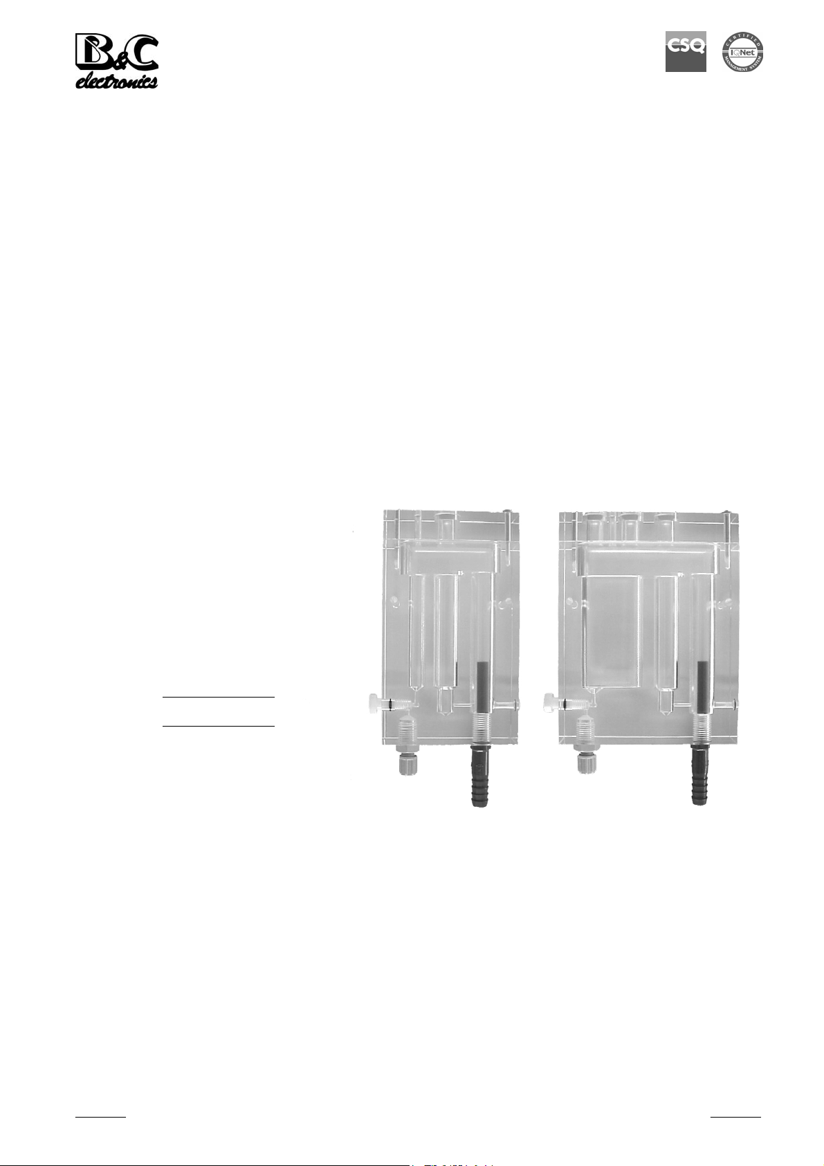
FLOW CELL
Option
REP N°
SZ 7231 SZ 7233
Cod. 28019723 - Rev. B - 10/05
B&C Electronics Srl - Via per Villanova 3 - 20040 Carnate (Mi) - Italy - P.IVA 00729030965
Tel +39 039 63 1721 - Fax +39 039 607 6099 – [email protected] - www.bc-electronics.it
Page 2

B&C Electronics SZ 7231 – SZ 7233
Index
1 DESCRIPTION............................................................................................................................. 3
2 SPECIFICATIONS....................................................................................................................... 4
2.1 SZ 7231 Specifications........................................................................................................ 4
2.2 SZ 7233 Specifications........................................................................................................ 4
3 INSTALLATION ......................................................................................................................... 5
4 OPERATION................................................................................................................................ 5
5 MAINTENANCE ......................................................................................................................... 6
Instruction Manual - Rev. B - 10/05 - 2 -
Page 3

B&C Electronics SZ 7231 – SZ 7233
1 DESCRIPTION
This flow cell series is designed for the use with potentiostatic residual chlorine monitors.
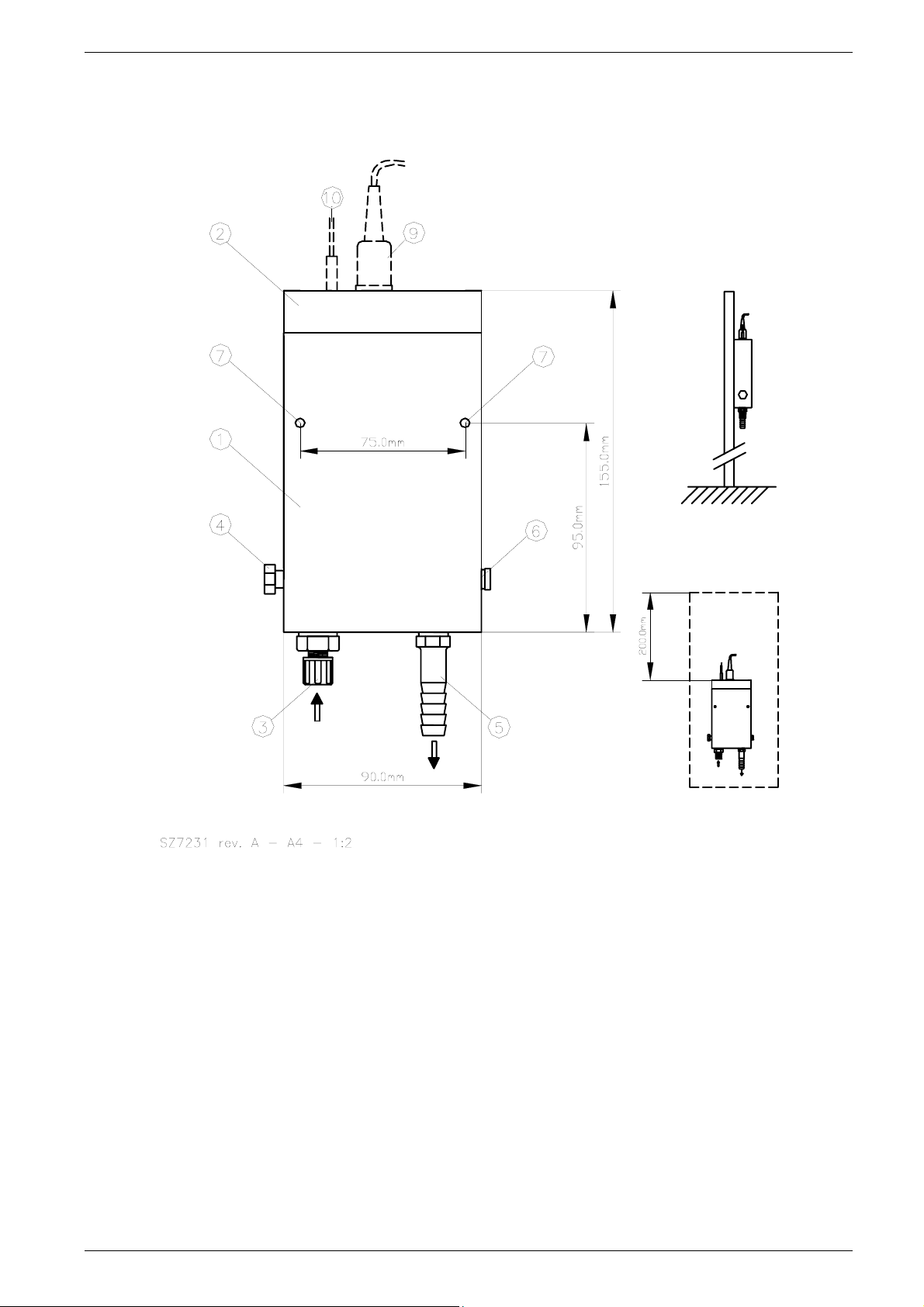
The chlorine electrode is inserted in the cell position 9 .
The RTD Pt100 is inserted in position 10 .
The constant head flow cell controls the liquid speed over a wide variation of the feeding flow.
The cells are provided with a screw 4 suitable for the flow adjustment.
The package includes 2 m of 4 x 6 mm pipe for the cell connection to the water being measured.
The water inlet is through the fitting 3 .
The water outlet is through the fitting 5 on the bottom of the cell.
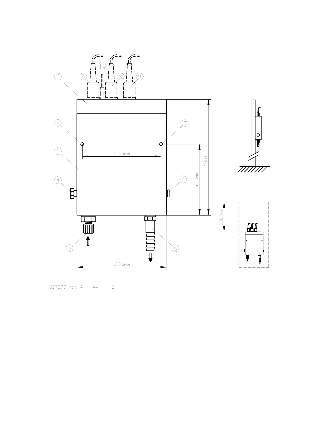
The cell SZ 7233 is designed for the insertion in the position 8 of the pH and ORP electrodes.
Electrodes must be inserted in the position suggested in this manual in order to have a correct
operation.
Instruction Manual - Rev. B - 10/05 - 3 -
Page 4

B&C Electronics SZ 7231 – SZ 7233
2 SPECIFICATIONS
2.1 SZ 7231 SPECIFICATIONS
Body transparent epoxy
Inlet 1/4" fitting
Overflow outlet 10 x 14 mm diameter pipe
Dimensions 150 x 90 x 40 mm
Fittings 1/4" for 4 x 6 mm pipe
Connection pipe 2 m 4 x 6 mm (included)
Water Flow approx. 10/30 l/hour
Temperature 0/50 °C
Sensors 12 mm diameter
RTD sensor 5 mm diameter
2.2 SZ 7233 SPECIFICATIONS
Body transparent epoxy
Inlet 1/4" fitting
Overflow outlet 10 x 14 mm diameter pipe
Dimensions 150 x 120 x 40 mm
Fittings 1/4" for 4 x 6 mm pipe
Connection pipe 2 m 4 x 6 mm (included)
Water Flow approx. 10/30 l/hour
Temperature 0/50 °C
Sensors 12 mm diameter
RTD sensor 5 mm diameter
Instruction Manual - Rev. B - 10/05 - 4 -
Page 5

B&C Electronics SZ 7231 – SZ 7233
3 INSTALLATION
The flow cell must be installed in vertical position close to the measuring instrument.
The flow assembly is wall mounted using the bolt holes 7 .
The overflow pipe connected to 5 must discharge in air, without any counter pressure (example into a
1" pipe).
4 OPERATION
- Insert the chlorine electrode in position 9 .
- Insert the RTD (if available) in position 10 .
- Connect the measuring electrode (and RTD) to the instrument following the specific
connections instruction.
- Adjust the screw 4 in order to have the over flow even in the minimum inlet water pressure
condition.
- When the inlet flow adjustment is critical, install a supplementary tap on the feeding pipe.
Instruction Manual - Rev. B - 10/05 - 5 -
Page 6

B&C Electronics SZ 7231 – SZ 7233
5 MAINTENANCE
The Chlorine electrode requires periodic maintenance.
When the platinum bands become fouled the sensitivity of the measuring decrease and it is necessary
to clean the platinum electrodes, pressing and rotating by hand a filter paper or similar.
Sensor maintenance should be performed every 4 weeks depending upon the severity of the sample
stream conditions.
Dirty applications will require more frequent maintenance, while high purity water applications will
require less frequent maintenance.
When some deposits or biological fouling are into the cell and internal holes, unscrew and remove the
cell cleaning screw 6 and the OR, clean the holes and reassembly the screw and the OR.
Instruction Manual - Rev. B - 10/05 - 6 -
Page 7
B&C Electronics SZ 7231 – SZ 7233
SZ 7231 CONNECTIONS
1. Body
2. Drilled cover
3. Inlet
4. Flow control
5. Outlet
6. Cell cleaning screw
7. Fixing holes
9. Chlorine electrode
10. RTD sensor
Fig. 1
Instruction Manual - Rev. B - 10/05 - 7 -
Page 8
B&C Electronics SZ 7231 – SZ 7233
SZ 7233 CONNECTIONS
1. Body
2. Drilled cover
3. Inlet
4. Flow control
5. Outlet
6. Cell cleaning screw
7. Fixing holes
8. pH / ORP electrode
9. Chlorine electrode
10. RTD sensor
Fig. 2
Instruction Manual - Rev. B - 10/05 - 8 -
Page 9

B&C Electronics SZ 7231 – SZ 7233
N O T E S
Instruction Manual - Rev. B - 10/05 - 9 -
 Loading...