

CERT. N. 9115 BCEL
INSTRUCTION MANUAL
UNI EN ISO 9001:2000
ST 6115
OPTICAL DISSOLVED OXYGEN
4-20 mA CURRENT LOOP
AUTOCLEAN
Option
S/N
REP N°
Range: 0/20 PPM
Power: 9/36 Vdc
Firmware: R 1.0x
Cod. 280166115 – Rev. A BC3531-A - Rev.01
B&C Electronics Srl - Via per Villanova 3 - 20040 Carnate (Mi) - Italy - P.IVA 00729030965
Tel +39 039 63 1721 - Fax +39 039 607 6099 – bc@bc-electronics.it - www.bc-electronics.it

B&C Electronics ST 6115
Index
1 DESCRIPTION..................................................................................................................................2
1.1 Principle of operation ...............................................................................................................2
1.2 Accessories ...............................................................................................................................2
2 TECHNICAL SPECIFICATIONS ....................................................................................................3
3 INSTALLATION ..............................................................................................................................5
3.1 How to use the auto clean sensor assembling...........................................................................5
3.2 How to use the probe without the cleaner ................................................................................5
3.3 Connections ..............................................................................................................................6
3.4 Connection to BC 7635 or BC 7335 controllers......................................................................6
4 CALIBRATION.................................................................................................................................7
5 MAINTENANCE ..............................................................................................................................7
6 RESET ...............................................................................................................................................8
WARRANTY CERTIFICATE...............................................................................................................11
REPAIRS................................................................................................................................................11
TECHNICAL SUPPORT .......................................................................................................................12
Instruction manual - Rev. A – 02/09
- 1 -

B&C Electronics ST 6115
1 DESCRIPTION
This unique submersible probe has been designed to measure dissolved oxygen based on fluorescent
technology.
The measuring system consists of:
- optical device complete with a layer of fluorescent material,
- electronic circuit with an exciting beam and fluorescence detection,
- built-in 2-wire 4/20 mA transmitter,
- digital inputs for calibration and configuration procedures,
- nozzle for the sensor autoclean by external pressure air.
The automatic temperature compensation is done internally by means of a built-in sensor.
Thanks to its 4/20 mA isolated output, the probe can be directly connected to a PLC or data logger,
without using amplifiers or other devices.
The probe can be connected to B&C Electronics controller BC 7635 or BC 7335, which provide the
power to the probe, the measuring readout, 2 set-points and an alarm.
The digital input of those controllers may keep in hold the functions during the autoclean cycle.
The most common applications of this probe include: water quality monitoring, municipal and
industrial water treatment and aquaculture.
1.1 PRINCIPLE OF OPERATION
A light beam of a specific wavelength is sent to a special fluorescent layer in contact with the sample.
The absorbed light energy is partially released as a light pulse with an higher wavelength.
This phenomena is called fluorescence.
If oxygen molecules are in contact with the sensing layer, the fluorescing is reduced (quenching).
By measuring the amount of quenching it is possible to determine the oxygen concentration.
The advantages of this measuring method are the absence of electrolyte and membrane, the possibility
to measure the oxygen concentration in water or in air, and a good sensitivity in a low oxygen
concentration.
1.2 ACCESSORIES
The installation of the probe needs few accessories to be selected among the following:
0012.450043 Extension pipe adapter.
0012.000624 Swivel mounting (it includes the 0012.450043 adapter)
0012.440040 33 m PVC tubing for pressure air.
Instruction manual - Rev. A – 02/09
- 2 -

B&C Electronics ST 6115
2 TECHNICAL SPECIFICATIONS
CURRENT LOOP
Current loop proportional to the d.oxygen: 4/20 mA
SENSOR TYPE
Optical DO
Sensing element: replaceable
SCALE
Measuring unit: ppm
Scale: 0.00/20.00 ppm
Resolution: 0.01 ppm
Drift: < 1% year
Response time: 95%< 60s
Automatic temperature compensation:
- internal table
(salinity 0ppm chloride)
Filter software
Response time to 90 % small signal: 120 seconds
Response time to 90% large signal: 40 seconds
TEMPERATURE
Compensation range: 0.0/50.0°C
Temperature coefficient: internal table
POWER SUPPLY
Voltage: 9/36 Vdc
Current: 22 mA max
RTD Pt100 built in sensor
Instruction manual - Rev. A – 02/09
- 3 -

B&C Electronics ST 6115
GENERAL SPECIFICATIONS
Diameter: 60 mm
Total length: 165 mm
Cable length: 10m
Material: PVC/silicon
Thread: 2” MNPT
Weight (body): 400 g
Weight (cable): 760 g
Operating temperature: -5°C/+50°C
Humidity: 0/95% without condensate
Storage temperature: -5°C/50°C
Protection (immersed part): IP68
Pressure: 1 bar max
Autoclean: built in nozzle
Inlet air fitting: tubing 1/4” internal, 3/8 external
Air pressure for cleaning: 3 bar max
Sensing element life: 3 years not exposed to sun light
EMC/RFI conformity: EN 61326
Marking: CE
Instruction manual - Rev. A – 02/09
- 4 -

B&C Electronics ST 6115
3 INSTALLATION
3.1 HOW TO USE THE AUTO CLEAN SENSOR ASSEMBLING
See the typical installation described in Fig. 2.
Before the immersion of the probe it is necessary to make the following:
- Provide an extension pipe with suitable length.
- Provide the PVC tubing 0012.440040 with suitable length.
- Prepare the 0012.450043 adapter.
- Insert the flexible tubing in the air connector.
- Insert the cable and the tubing in the adapter 0012.540043 and screw it on the probe.
- Insert the extension pipe and screw it on the adapter.
The pressure air provided by the customer must be a clean air at 3 bar max.
The typical cleaning time is 15 seconds and the typical cleaning frequency is 2 times/day, but it is
depending of the application and the actual efficiency of the cleaning action.
-----------------WARNINGS
------------------
Higher cleaning frequency could reduce the life of the DO sensing element.
Avoid a long exposure to sun light, which will reduce the life of the DO sensing element.
3.2 HOW TO USE THE PROBE WITHOUT THE CLEANER
Before the immersion of the probe, follow the above procedure but:
- Do not install the flexible tubing.
- Install a stopper on the air line connector in order to avoid the water entering into the room
between the adapter and the probe when the probe is submersed.
-----------------WARNINGS
------------------
Without the stopper the water will damage the cable and it may leak inside the probe.
Instruction manual - Rev. A – 02/09
- 5 -

B&C Electronics ST 6115
3.3 CONNECTIONS
Connect the probe to the meter by following the marked wire of the cable.
The normal operation needs just the connection of green and white wires, which are protected against
accidental inversion.
The shield is not connected to the probe but it must be connected to the ground.
Wires color function
shield not connected
yellow S (for calibration)
grey Z (for calibration)
brown gnd (for calibration)
green + current loop
white - current loop
Avoid the cable interruptions.
If necessary use high isolation junction box and the extension cable p/n 2423405 (5x0.25 – D 5.70 mm)
Keep the cable far from power cables even inside of the switch board.
The wires S, Z and gnd are dedicated to the factory calibration and they must be kept isolated when the
probe is powered.
Accidental contact each other can modify the calibration to be restored as described in the chapter 6.
3.4 CONNECTION TO BC 7635 OR BC 7335 CONTROLLERS
Connect the optical DO probe to the BC 7635 or BC 7335 in order to make easier the application
because of the following features of the controllers:
- scale selection flexibility
- digital inputs to keep in hold the unit during the autoclean cycle
- easy zero and sensitivity adjustment
- easy calibration of the dual set point
- min max alarm relay
- 0/20 mA or 4/20 mA isolated output
Connect the probe to the controller as follow:
wires color BC 7635 terminals BC 7335 terminals
green 20 20
white 22 22
Instruction manual - Rev. A – 02/09
- 6 -

B&C Electronics ST 6115
4 CALIBRATION
The DO probe is delivered with zero and sensitivity factory calibration.
The 0.00 PPM value corresponds to the 4 mA signal and the 20.00 PPM value corresponds to 20 mA
signal from the probe.
The user can calibrate the system in the field by using the zero and sensitivity adjustment of the PLC
or the controller.
Before the above calibration keep the probe hydrated at least 24 hours into the water.
Effect the zero adjustment into a bisulphite solution or as alternative with nitrogen/argon gas.
Effect the sensitivity calibration in air saturated water or as alternative in air.
The calibration may require 5 or 10 minutes for the stabilization, if the body temperature is different
than zero solution or room temperature.
Contact our customer service for assistance if the probe is used in sea water.
5 MAINTENANCE
When the auto clean system is installed, the cleaning of the optical sensing element is done
automatically.
Just remove periodically any external scales from the probe if necessary.
If the auto clean system is not installed, clean periodically the optical sensing element on the bottom of
the probe.
The frequency of the cleaning is depending of the application and the nature and the concentration of
the suspended solids.
Clean the optical sensing element before the calibration of the meter.
Clean by using a soft and wet paper filter or similar.
Press gently on the optical sensing element in order to avoid scratches.
Use eventually a low concentration acid.
In case of malfunctioning, send back the probe to the factory for the replacement of the optical
sensing disk.
Instruction manual - Rev. A – 02/09
- 7 -

B&C Electronics ST 6115
6 RESET
The cable includes 3 wires to be connected to the corresponding digital inputs of the probe in order to
perform the following functions:
- reset of the optical parts efficiency
- reset to the zero and sensitivity calibration of the probe.
The above operations are effected during the factory calibration of the probe and are necessary after
the replacement of the dissolved oxygen sensing disk or in case of strong loss of the sensor response.
During the normal operation in the field those wires are not connected and they must be kept isolated.
Any accidental contact of within two wires could generate wrong calibration of the probe.
We suggest to return the probe to B&C electronics in case of resetting of the probe calibration or
replacement of the sensing optical disk.
Instruction manual - Rev. A – 02/09
- 8 -

B&C Electronics ST 6115
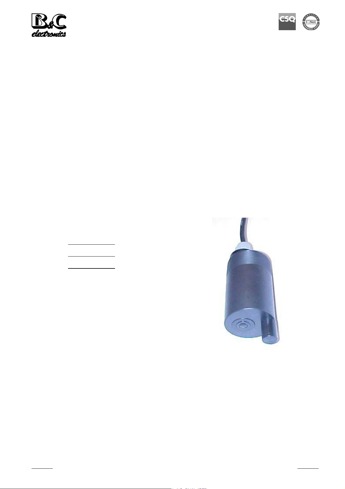
DIMENSIONS
Description Connections
1. Cable Shield not connected
2. Air input Yellow S (for calibration)
3. Thread Grey Z (for calibration)
4. Air nozzle Brown gnd (for calibration)
5. Sensing element Green + current loop
White - current loop
Fig. 1
Instruction manual - Rev. A – 02/09
- 9 -

B&C Electronics ST 6115
TIPICAL INSTALLATION
1. Swivel mounting (0012.000624)
2. Extension pipe
3. Adapter (0012.450043)
4. DO sensor with autoclean nozzle
5. Rain protection
6. Cable and air tubing
7. Rail
Fig. 2
Instruction manual - Rev. A – 02/09
- 10 -

B&C Electronics ST 6115
WARRANTY CERTIFICATE
1) Your product is covered by B&C Electronics Warranty for 5 years (sensing element
excluded) from the date of shipment.
In order for this Warranty to be valid, the Manufacturer must determine that the instrument
failed due to defective materials or workmanship.
2) The Warranty is void if the product has been subject to misuse and abuse, or if the damage
is caused by a faulty installation or maintenance.
3) The Warranty includes the repair of the instrument at no charge. All repairs will be
completed at the Manufacturer’s facilities in Carnate, Italy.
4) B&C Electronics assumes no liability for consequential damages of any kind, and the buyer
by accepting this equipment will assume all liability for the consequences of its use by the
Customer, his employees, or others.
REPAIRS
1) In order to efficiently solve your problem, we suggest You to ship the instrument along
with the Technical Support’s Data Sheet (following page) and a Repair Order.
2) The estimate, if requested by the Customer, is free of charge when it is followed by the
Customer confirmation for repair. As opposite, if the Customer shall not decide to have the
instrument repaired, he will be charged to cover labor and other expenses needed.
3) All instruments that need to be repaired must be shipped pre-paid to B&C Electronics. All
other expenses that have not been previously discussed will be charged to Customer.
4) Our Sales Dept. will contact You to inform You about the estimate or to offer you an
alternative, in particular when:
- the repairing cost is too high compared to the cost of a new instrument,
- the repairing results being technically impossible or unreliable
5) In order to quickly return the repaired instrument, unless differently required by the
Customer, the shipment will be freight collect and through the Customer’s usual forwarder.
B&C Electronics Srl - Via per Villanova 3 - 20040 Carnate (Mi) - P.IVA 00729030965
Tel (+39) 039 63 1721 - Fax (+39) 039 607 6099 - info@bc-electronics.it - www.bc-electronics.it
Instruction manual - Rev. A – 02/09
- 11 -

B&C Electronics ST 6115
TECHNICAL SUPPORT
Data sheet
In case of damage, we suggest You to contact our Technical Support by email
or phone. If it is necessary for the instrument to be repaired, we recommend to
photocopy and fill out this data sheet to be sent along with the instrument, so to
help us identifying the problem and therefore accelerate the repairing process.
□ ESTIMATE □ REPAIR
COMPANY NAME
ADDRESS ZIP CITY
REFER TO MR./MISS. PHONE
MODEL S/N DATE
Please check the operator’s manual to better identify the area where the problem seems to be
and please provide a brief description of the damage:
□ SENSOR □ ANALOG OUTPUT
□ POWER SUPPLY □ SET POINT
□ CALIBRATION □ RELAY CONTACTS
□ DISPLAY □ PERIODICAL MALFUNCTIONING
¾ DESCRIPTION
................................................................................................................................................................
................................................................................................................................................................
................................................................................................................................................................
................................................................................................................................................................
................................................................................................................................................................
................................................................................................................................................................
................................................................................................................................................................
................................................................................................................................................................
Instruction manual - Rev. A – 02/09
- 12 -
 Loading...