

CERT. N. 9115 BCEL
INSTRUCTION MANUAL
UNI EN ISO 9001:2000
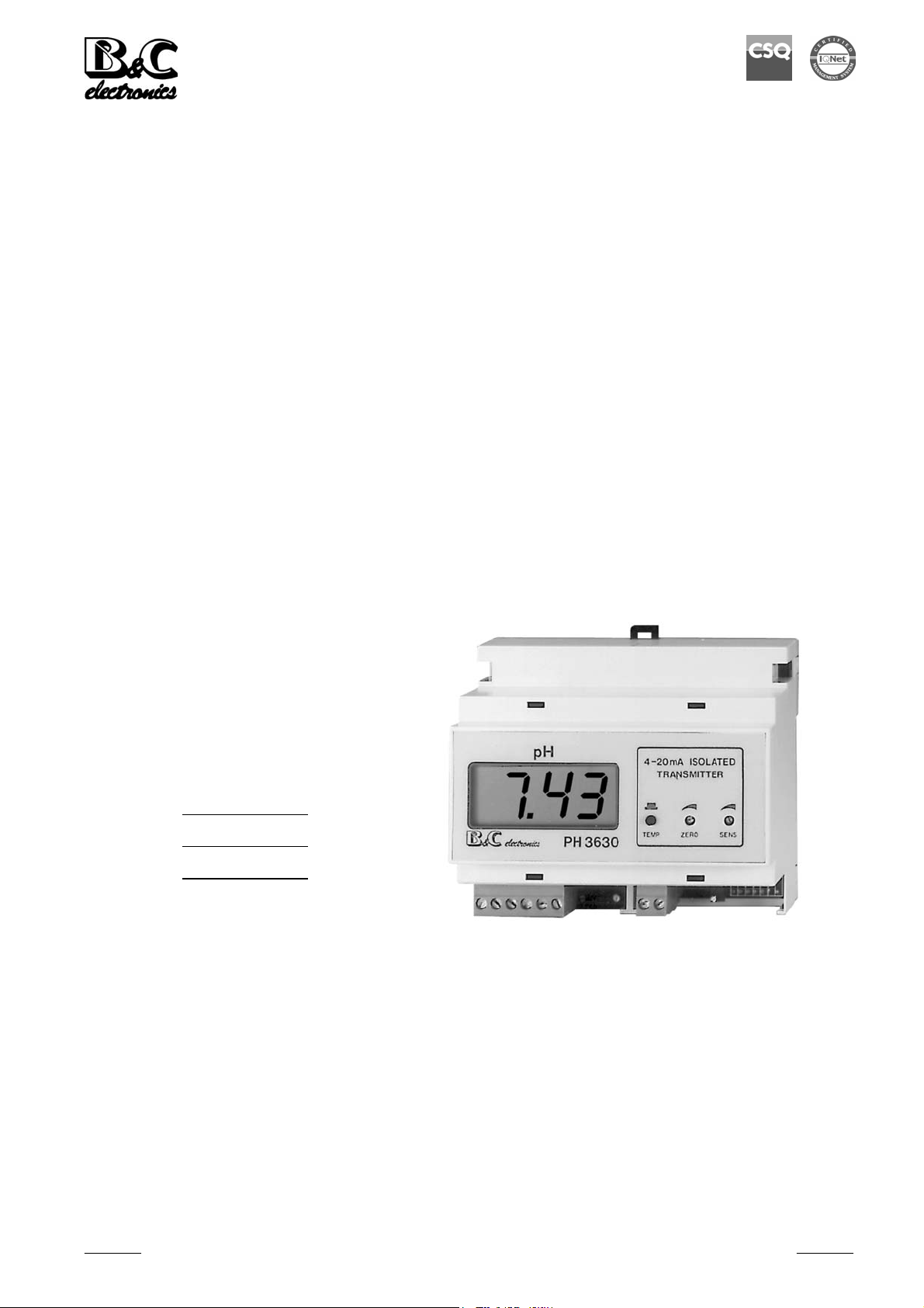
PH 3630
2-WIRE pH TRANSMITTER
DIN RAIL
pH Scale: 0.00/14.00 pH
Temp. Scale: -10.0/+120.0 °C
Power Supply: 10/30 Vdc
Option
S/N
REP N°
Cod. 28001363 - Rev. B - 10/05 - Valid from S/N 39263
B&C Electronics Srl - Via per Villanova 3 - 20040 Carnate (Mi) - Italy - P.IVA 00729030965
Tel +39 039 63 1721 - Fax +39 039 607 6099 – bc@bc-electronics.it - www.bc-electronics.it

B&C Electronics PH 3630
Index
1 GENERAL .........................................................................................................................................3
2 FUNCTIONAL DESCRIPTION .......................................................................................................3
3 PHYSICAL DESCRIPTION .............................................................................................................3
4 SPECIFICATIONS............................................................................................................................4
5 PHYSICAL INSTALLATION..........................................................................................................5
6 ELECTRICAL INSTALLATION .....................................................................................................6
6.1 Connecting the power...............................................................................................................6
6.2 Connecting the electrode (probe)..............................................................................................6
6.3 Connecting the temperature sensor...........................................................................................7
7 SYSTEM CHECKING ......................................................................................................................8
8 OPERATING THE SYSTEM ...........................................................................................................9
8.1 Pre-operation check ..................................................................................................................9
8.2 Electrical calibration.................................................................................................................9
8.3 Calibrating the pH transmitter ................................................................................................10
9 NORMAL OPERATION.................................................................................................................11
9.1 Manual temperature compensation......................................................................................... 11
10 PREVENTIVE MAINTENANCE...................................................................................................12
10.1 Transmitter..............................................................................................................................12
10.2 Sensor .....................................................................................................................................12
11 TROUBLESHOOTING GUIDE .....................................................................................................13
Instruction Manual - Rev. B - 10/05
- 2 -

B&C Electronics PH 3630
1 GENERAL
This manual applies to the PH 3630 digital 2-wire transmitter DIN RAIL housing.
It explains the purpose of the equipment, describes the components of the system and the procedures
for installing, operating and calibrating the equipment.
Some maintenance suggestions are also provided.
2 FUNCTIONAL DESCRIPTION
This transmitter, when connected to the pH electrode, provides a digital readout of the pH of aqueous
solutions.
The transmitter will perform manual or automatic Temperature compensation to correct pH readings
for Temperature related variations. Temperature information is displayed by pushing button "2"
marked "Temp".
The transmitter provides an isolated 4/20 mA output, proportional to the pH value which is suitable for
Data Acquisition Systems, Recorders, Controllers or other input Devices that require a 4-20 mA input.
The front panel contains trimmer pots for Zero and Slope adjustments. "Zero" is adjusted with trimmer
"3" and "Slope" is adjusted with trimmer "4".
The unit is protected against power supply inversion.
3 PHYSICAL DESCRIPTION
The transmitter enclosure is designed for DIN Rail mounting.
It consists of a plastic case with front panel which is coated by a polycarbonate membrane , to ensure
maximum anticorrosion characteristics.
For field applications mounting in a splash proof or weather resistant box is suggested.
Connections to power supply, loads, recorder, RTD, electrodes and probe are installed onto the
terminal block connector.
Instruction Manual - Rev. B - 10/05
- 3 -

B&C Electronics PH 3630
4 SPECIFICATIONS
Display: LCD
Inputs: pH electrode
RTD Pt100 3 wires
Output: 4/20 mA dc isolated
Scales: 0.00/14.00 pH
-10.0/120.0 °C
Temp. Compensation: manual or automatic
Zero: adjustable +/- 15%
Sensitivity (Span): adjustable from 86 % to 112 %
Input Current: < 2 pA
Input Resistance: > 1012 Ω
Operating Temperature: 0/50 °C
Operating Humidity: 95 % without condensation
Power supply: 10/30 Vdc
Isolation: 500 V Input to Output
Terminal block: detachable
Net Weight: 200 g
Dimensions: 105 x 95 x 58 mm (6 modules)
Mounting: DIN Rail
Instruction Manual - Rev. B - 10/05
- 4 -

B&C Electronics PH 3630
5 PHYSICAL INSTALLATION
The transmitter must be installed into an enclosure for outdoor or indoor use and may be located close
to the measuring point or some distance away in a control area.
To ensure best operational performance, it is suggested that the transmitter be located within 30 feet of
the electrode, and long cable runs be made with conventional coaxial electrode cable.
The transmitter's housing is designed for DIN Rail mounting.
The electrode's coax cable must be protected by a sheath and not installed near power cables.
Extension cables should be avoided. When necessary, always use only high insulation terminals.
When installing "in line" electrodes it is suggested to follow the specific instructions given by the
sensor's manufacturer.
Instruction Manual - Rev. B - 10/05
- 5 -

B&C Electronics PH 3630
6 ELECTRICAL INSTALLATION
The electrical installation consists of:
- connecting the power supply to the transmitter;
- connecting the electrode or the probe to the transmitter;
- connecting the Temperature sensor.
(See Fig. 3)
All connections within the transmitter are made on the terminal block.
6.1 CONNECTING THE POWER
- Connect dc power "+" to terminal "1" marked "+".
- Connect the terminal marked "-" to terminal "+" of the load.
- Connect dc power "-" to terminal "-" of the load.
The unit is protected against eventual inverted connections
WARNING:
Verify the supply voltage prior to connection to the transmitter
6.2 CONNECTING THE ELECTRODE (PROBE)
Electrode cabling is a critical component for trouble free system operation.
- Use a low noise coax cable on overall length between sensor and input terminals of the
Transmitter;
- low noise cable has, in general, a black conductive layer between the central conductor and the
shield. Be sure this layer is removed;
- extension cables should be avoided. When necessary, always use only high insulation terminals;
- avoid installing cable near any power cables;
- connect the shield of the coax cable (Reference electrode) to the terminal "11" marked "R";
- connect the central conductor (Glass electrode) to the terminal "10" marked "V".
Instruction Manual - Rev. B - 10/05
- 6 -

B&C Electronics PH 3630
6.3 CONNECTING THE TEMPERATURE SENSOR
The model PH 3630 features Automatic Temperature Compensation carried out by means of a
RTD Pt100.
The Temperature sensor has to be installed in the same solution being measured, close to the electrode
in-line or in the tank.
ATTENTION
In order to activate the ATC function, prior to connecting the RTD between terminal "4-5-6" marked
"T1-T2-T3", it is necessary to remove the jumpers from terminals "3-4" and "5-6".
These jumpers must be reinstalled when operating the transmitter in Manual Temperature mode.
The RTD connection as above described will also provide a digital display of Temperature values.
The sample Temperature value is displayed by pushing the Key pad "2" marked "TEMP" on the front
panel. The Temperature readout will not disrupt the measuring functions of the transmitter.
Instruction Manual - Rev. B - 10/05
- 7 -

B&C Electronics PH 3630
7 SYSTEM CHECKING
Before connecting the system to the power supply:
- check that all connections are installed correctly;
- check that all cables are properly fastened to prevent strain on the connections;
- check that all terminal-strip connections are mechanically and electrically solid.
Instruction Manual - Rev. B - 10/05
- 8 -

B&C Electronics PH 3630
8 OPERATING THE SYSTEM
8.1 PRE-OPERATION CHECK
The system's controls and indicators are all located on the front panel.
The transmitter LCD will be displayed to indicate that the unit is on.
Push the Key pad "2" to check the sample Temperature (if RTD is connected), or the Manual
Temperature value (RTD not connected and jumpers installed).
The circuit boards of the unit are pre-adjusted at the factory.
If sensors and probes have been installed correctly as previously described, the system should operate
correctly requiring only electrode calibration.
WARNING:
Improper wiring connections which result in damage to the transmitter are not covered under warranty
8.2 ELECTRICAL CALIBRATION
The following procedures can be used to verify that the pH transmitter is operating satisfactorily, and
it can be repeated periodically to check that the transmitter is maintaining electrical calibration:
- connect a pH Simulator to terminals "10-11" marked " V - R ";
- simulate pH values over the entire scale;
- adjust "Zero" and "Slope" with trimmers located on the front panel;
- check the input insulation following the instructions of the Simulator. Input Current must be
lower than 2 pA.
Instruction Manual - Rev. B - 10/05
- 9 -

B&C Electronics PH 3630
8.3 CALIBRATING THE pH TRANSMITTER
All pH Instrumentation manufactured by B&C Electronics are laboratory calibrated and verified using
a standard pH electrode with a zero point at 7.00 pH. Slope is verified at 20°C.
Before using the electrode or calibrating, check that the electrode Glass membrane has been stored
wet.
If the protective cap is empty and the electrode is dry, immerse the electrode in a buffer solution or tap
water (do not use distilled water) for three hours before operating.
See general instructions provided by the electrode manufacturer for further details.
Buffer solutions with a pH value of 4-7-9 are available to calibrate the meter.
Immerse the electrode in the buffer solution pH = 7 and adjust the trimmer marked "zero".
Immerse the electrode in the buffer solution pH = 4 or pH = 9 and adjust trimmer marked "sens".
If Automatic Temperature Compensation is to be used, the RTD must also be immersed into the buffer
solutions. Allow the RTD to reach thermal equilibrium before adjusting the "Zero" and "Sens"
trimmers.
Check the calibration periodically.
Instruction Manual - Rev. B - 10/05
- 10 -

B&C Electronics PH 3630
9 NORMAL OPERATION
As solution passes the installed electrode the display will indicate instantly the pH value of the
solution currently being measured.
9.1 MANUAL TEMPERATURE COMPENSATION
The manual Temperature compensation is available when the RTD Pt100 is not installed.
- Install the jumpers between "3-4" and "5-6".
- Push the Key pad "2" on the front panel (Fig. 1) and adjust the trimmer "R5" marked " T MAN "
to indicate the desired Temperature value on the display. (Fig. 3)
Instruction Manual - Rev. B - 10/05
- 11 -

B&C Electronics PH 3630
10 PREVENTIVE MAINTENANCE
10.1 TRANSMITTER
Quality components have been used to ensure a high level of reliability.
Frequency of maintenance or re-calibration is variable based on each particular application.
As with any electronic Device, the mechanical components, such as potentiometers and connectors,
are the most probable sources of potential problems.
- Check for damage of the electrolytic capacitors if the meter is exposed to temperatures above
60°C,
- check for damage in all the electronic components if the meter is subjected to excessive voltage
or power surges,
- check for damage of the electronic and mechanical components if the meter is dropped,
- repeat the pre-operation check periodically to ensure proper operation,
- check that all the connections are free from moisture and contamination such as rust
and corrosion.
WARNING:
Disconnect the power supply to the transmitter before performing the following procedures:
- Inspect the printed circuit boards for dirt and corrosion; clean as necessary and blow dry.
- Tighten all the terminal-board connections and mounting hardware.
10.2 SENSOR
Coatings on the pH electrodes glass measuring surface can affect operation.
Solutions which are high in alkaline content (above 10 pH) and or solutions which contain slurries,
oils, grease, etc., will require regular cleaning and inspection of the electrode's glass measuring
surface.
Suggested methods for cleaning the electrode include chemical cleaning (except hydrofluoric acid) and
non abrasive detergent washing.
Also, ultrasonic methods may be used.
Instruction Manual - Rev. B - 10/05
- 12 -

B&C Electronics PH 3630
11 TROUBLESHOOTING GUIDE
Symptoms
LCD not displayed
Display reading too
high/low
Display reading does not
change
Slope will not adjust
Probable cause
power source problem
incorrect power wiring
electrode failure; meter
uncalibrated
electrode damage; short circuit
electrode damage; open Temp.
circuit
Remedy
check power supply
check wiring
clean electrode
calibrate with buffers
electrode replacement
check cable
electrode replacement
check ATC sensor/jumpers
Instruction Manual - Rev. B - 10/05
- 13 -

B&C Electronics PH 3630
FRONT PANEL
1. Display
2. Temperature display actuator
3. Zero calibration
4. Slope calibration
Fig. 1
Instruction Manual - Rev. B - 10/05
- 14 -

B&C Electronics PH 3630
DIMENSIONS
(measures in mm)
Fig. 2
Instruction Manual - Rev. B - 10/05
- 15 -

B&C Electronics PH 3630
REAR PANEL CONNECTIONS
1. Loop supply (+ input)
2. Loop supply (- input)
3. 4. Manual temperature compensation jumper
5. 6. Manual temperature compensation jumper
4. 5. 6. RTD input (A.T.C.)
10. pH input (HI)
11. Reference input (LO)
R5 Manual temperature control
Fig. 3
Instruction Manual - Rev. B - 10/05
- 16 -

B&C Electronics PH 3630
N O T E S
Instruction Manual - Rev. B - 10/05
- 17 -
 Loading...