

CERT. N. 9115 BCEL
INSTRUCTION MANUAL
UNI EN ISO 9001:2000
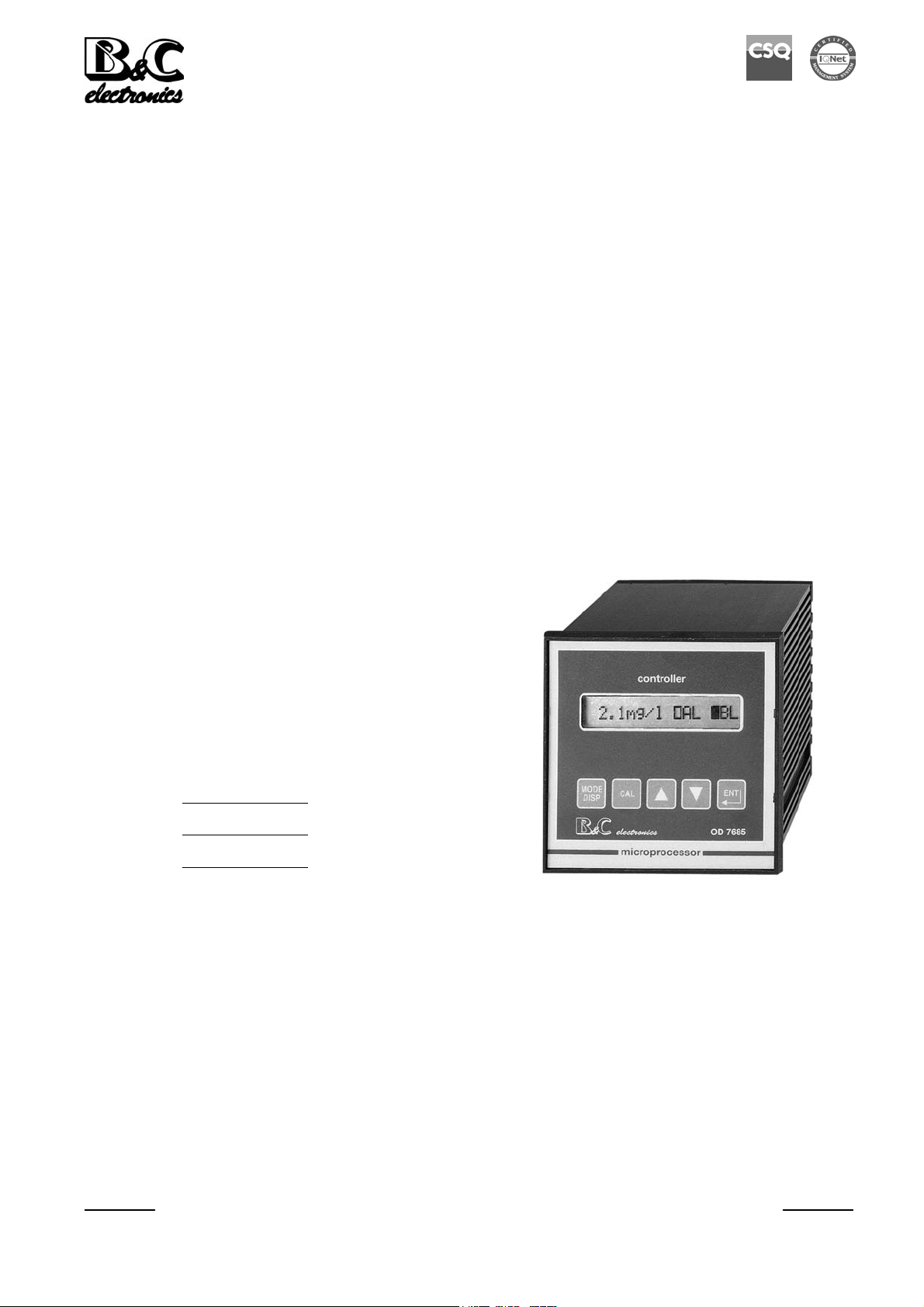
OD 7685.110
OPTICAL D.OXYGEN CONTROLLER
D.O. scales: 0/400 - 0/200,0 %air
0/400 - 0/200,0 mmHg
0/40 - 0/20,00 ppm
0/40 - 0/20,00 mg/l
Temperature: -2/+52 °C
-28,4/125,6 °F
Option
S/N
REP N°
Power supply: 110/220 Vac
Software: R2.0x
Cod. 280067622 - Rev. A
B&C Electronics Srl – Via per Villanova 3 – 20040 Carnate (MB) – Italy P.IVA 00729030965
Tel +39 039 631 721 – Fax +39 039 607 6099 bc@bc-electronics.it - www.bc-electronics.it

B&C Electronics OD 7685.110
Index
1 DESCRIPTION 3
1.1 Measuring system ...................................................................................................................3
1.2 Optical D.O. measuring principle...........................................................................................4
1.3 Sensors and accessories ..........................................................................................................4
2 SPECIFICATIONS 5
2.1 Functional specifications ........................................................................................................5
2.2 Technical specifications..........................................................................................................7
2.3 Physical description..............................................................................................................11
3 OPERATING THE SYSTEM
12
3.1 Keys function........................................................................................................................13
3.2 Readout sequences................................................................................................................14
3.3 Calibration sequences ...........................................................................................................16
3.3.1 Zero and sensitivity calibration ......................................................................................16
3.3.2 Secondary parameters calibration...................................................................................20
3.3.3 Temperature calibration..................................................................................................22
3.3.4 Set point A and B............................................................................................................23
3.3.5 On/Off parameters ..........................................................................................................24
3.3.6 Auto clean parameters ....................................................................................................25
3.3.7 Visualizations .................................................................................................................27
3.3.8 Configuration..................................................................................................................28
3.3.9 Keyboard locked/unlocked .............................................................................................28
3.3.10 LCD contrast...................................................................................................................29
3.3.11 Main display ...................................................................................................................29
3.3.12 Temperature measuring unit...........................................................................................29
3.3.13 Access number................................................................................................................29
3.3.14 Measuring unit................................................................................................................30
3.3.15 Software filter LARGE...................................................................................................30
3.3.16 Software filter SMALL...................................................................................................30
3.3.17 Input related to the analog output Nr 1...........................................................................30
3.3.18 Analog output Nr1 parameters........................................................................................30
3.3.19 Input related to the analog outpt Nr 2.............................................................................30
3.3.20 Analog output Nr 2 parameters.......................................................................................31
3.3.21 Set-point A function .......................................................................................................31
3.3.22 Set-point B function........................................................................................................31
3.3.23 Cleaning function ...........................................................................................................31
3.3.24 Number of clearing cycle................................................................................................31
3.3.25 Compressor charge time (relay D off)............................................................................31
3.3.26 Compressor discharge time (relay D on)........................................................................32
3.3.27 Hold ................................................................................................................................32
3.3.28 Access number................................................................................................................32
4 INSTALLATION
33
4.1 Physical installation..............................................................................................................33
4.2 Electrical installation ............................................................................................................33
4.2.1 Connecting the optical DO probe with the built in temperature sensor .........................33
4.2.2 Connecting the relays .....................................................................................................34
Instruction manual - Rev. A - 07/09
- 1 -

B&C Electronics OD 7685.110
4.2.3 Connecting the analog output .........................................................................................34
4.2.4 Checking.........................................................................................................................34
5 PREVENTIVE MAINTENANCE 35
WARRANTY CERTIFICATE ..............................................................................................................38
REPAIR .................................................................................................................................................38
TECHNICAL SUPPORT ......................................................................................................................39
Instruction manual - Rev. A - 07/09
- 2 -

B&C Electronics OD 7685.110
1 DESCRIPTION
1.1 MEASURING SYSTEM
The Dissolved Oxygen monitoring system consists of two parts:
- the measuring/regulating instrument which is discussed in this instruction manual
- the optical dissolved oxygen probe
The system could be implemented with additional devices for field application:
recorder, remote display, PID regulators, sensor cleaner.
Instrument
This instrument carries out the following functions:
1) dissolved oxygen measuring when connected to the sensor
2) manual/automatic d.oxygen regulation, if suitable devices are connected to the output relays
3) temperature measuring, if an RTD Pt1000 is connected
4) manual or automatic compensation of temperature, pressure, salinity and relative humidity effects
6) D.O. and temperature acquisition, when connected to a recorder or a data logger
7) sending data via a serial interface, if the 091.701 option "RS232" is installed
8) external device activation for the sensor cleaning
Sensor
The B&C Electronics OD 8382 optical DO sensor or special galvanic sensor are suitable for this
instrument.
The sensor installation should allow a continuous contact with the sample, in a position with sufficient
stirring and exchange of sample.
In some applications the use of sensor cleaning devices is suggested.
Instruction manual - Rev. A - 07/09
- 3 -
B&C Electronics OD 7685.110
1.2 OPTICAL D.O. MEASURING PRINCIPLE
A light beam of a specific wavelength is sent to a special fluorescent layer in contact with the sample.
The absorbed light energy is partially released as a light pulse with an higher wavelength.
This phenomena is called fluorescence.
If oxygen molecules are in contact with the sensing layer, the fluorescing is reduced (quenching).
By measuring the amount of quenching it is possible to determine the oxygen concentration.
The advantages of this measuring method are the absence of electrolyte and membrane, the possibility
to measure the oxygen concentration in water or in air, a not sensitivity to the flow, and a good
sensitivity in a low oxygen concentration.
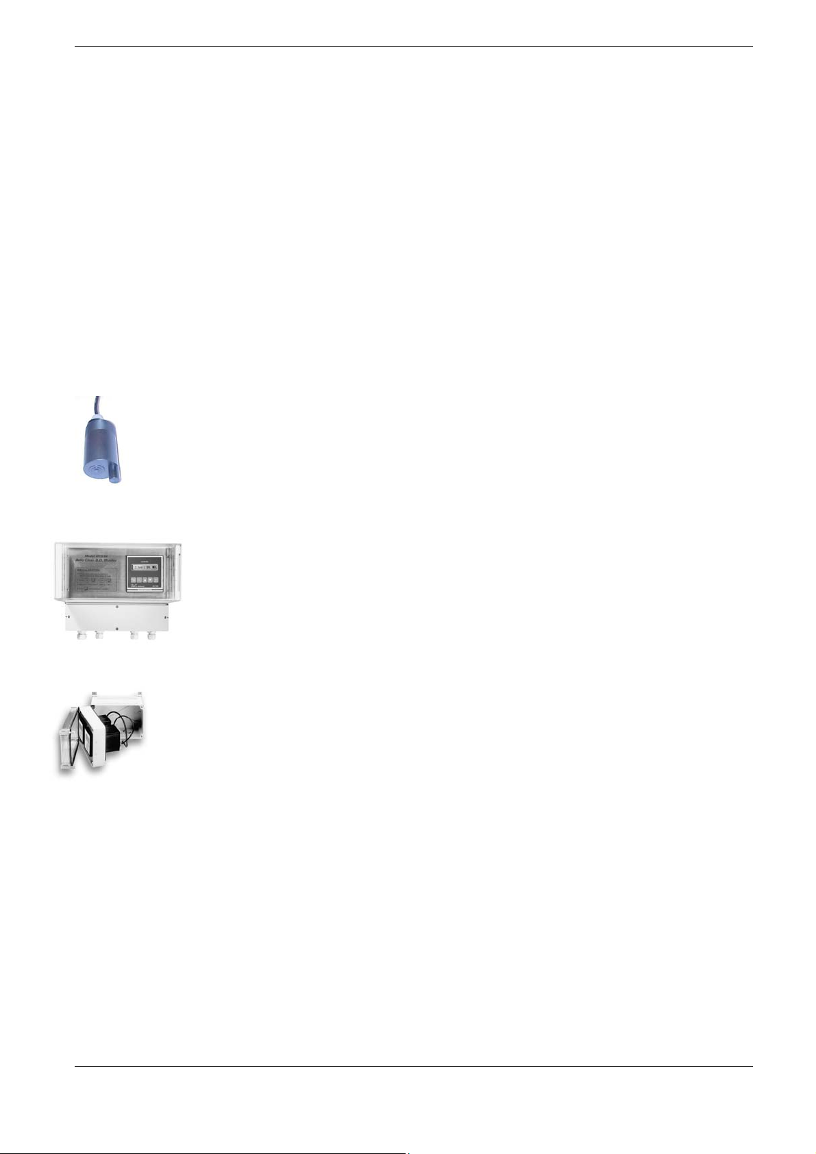
1.3 SENSORS AND ACCESSORIES
To be ordered separately:
OD 8382 Auto clean optical DO probe, 10 m cable
OD 8112 Pressure air cleaner+controller
BC 931.2 Enclosure for one unit. IP65
BC 931.3 Enclosure for two units. IP65
Instruction manual - Rev. A - 07/09
- 4 -

B&C Electronics OD 7685.110
2 SPECIFICATIONS
2.1 FUNCTIONAL SPECIFICATIONS
Input
The instrument accepts input from the OD 8382 optical DO probe or the AT amplified galvanic cell.
A second input is provided for 2 or 3 wires Pt1000 RTD temperature sensors.
Temperature compensation
The unit is supplied with manual or automatic temperature compensation and temperature
information may be displayed on the LCD.
The instrument detects of the absence or malfunctioning of the temperature sensor and automatically
switches to manual compensation.
Secondary parameters
The unit is supplied with pressure, salinity and relative humidity manual compensation.
Measuring ranges
The input range may be selected in PPM, mg/l, % air saturation and mmHg partial pressure.
The temperature range is selectable in °C or in °F.
Dual Analog output
Either a 0/20 mA or 4/20 mA isolated output may be selected, for use as an interface with computers
or data loggers.
A special routine allows selection of the analog output range.
The output current may be set anywhere from 0 to full scale.
Control relays
The D.O. monitor is equipped with two SPDT control relays.
Each control relay may be programmed for set-point, high/low, hysteresis or delay time actuation.
When the unit is configured as main display DO +SET, the full display indicates the current settings
and current status of each relay.
Cleaning function
The instrument features two relays (C-D) for autocleaning cycle.
The cleaning function may be activated automatically or manually.
The user may select:
- cleaning time
- holding time
- cycle repetition time
Instruction manual - Rev. A - 07/09
- 5 -

B&C Electronics OD 7685.110
During the CLEAN and HOLD time:
- flashing messages will appear
- analog outputs are maintained in hold
- relays A and B are deactivated
Calibration mode
The instrument may be automatically calibrated in air.
Manual calibration may also be performed.
Software filter
The unit is provided with a dual programmable software filter, to be inserted when the readout is not
stable.
Configuration
The electronics for the D.O. monitor system are designed to be as flexible as possible.
A number of programming functions are provided in the configuration menu and are protected by an
access number, which must be entered to allow changes in this setting.
The main display can be configured in order to show the D.O. and temperature values or the D.O.
value and set point status.
Keyboard lock
The keys on the front panel of the monitor can be used for both changing the display and for
calibrations and set-point adjustments.
When the monitor is shipped, all functions are accessible.
However, the adjustment and calibration functions may be locked in order to prevent unauthorized
adjustments to the instrument.
Options
091.404 24 Vac power supply
091.4143 9/36 Vdc power supply
091.701 RS232 isolated output
The output sends the data (D.O. value, °C) to the serial port
Instruction manual - Rev. A - 07/09
- 6 -

B&C Electronics OD 7685.110
2.2 TECHNICAL SPECIFICATIONS
The Default values are correspondent to the factory calibration values.
Parameters marked by "*" can be modified in the Configuration procedures.
1) DO SENSOR
* Main display: DO+SET/DO+TEMP
Input: from optical DO sensor
or from amplified ATI galvanic cell
Input signal at 20 °C (68 °F): 83.2/1040 mV
Sensor sensitivity: 20%/250 %
Temperature compensation: internal table
Reference temperature: 20°C (68 °F)
* Scales: % air saturation: 0/400 - 0/200.0 % air
ppm: 0/40.0 - 0/20.00 ppm
mg/l: 0/40.0 - 0/20.00 mg/l
Partial O2 pressure: 0/400 - 0/200.0 mmHg
Zero adjustment: +/- 40 mV
Sensitivity adjustment: 200/250%
Display resolution at 20°C: 1/1000
Auto calibration (function of temp.-press.-UR)
Manual calibration (through up/down keys)
Software filter 90% RT:
* Large signal variation: 0.5/50.0 seconds
* Small signal variation: 0.5/50.0 seconds
2) SECONDARY PARAMETERS
Pressure: 500/800 mmHg 760 mmHg
Salinity (chlorides): 0/60000 ppm 0 ppm
Relative Humidity: 0/100 % 50 %
3) TEMPERATURE
Measuring unit: °C/°F
Input: RTD Pt1000
Connection: 2/3 wires
Measuring and compensation range: -2/+52 °C (24,8/125,5 °F)
Resolution: ± 0.1 °C (0,1 °F)
Zero: ± 2°C (± 3,6 °F) 0°C
Manual temperature: 0/50°C (32/122 °F) 20°C
Instruction manual - Rev. A - 07/09
Default
DO+SET
416 mV
0/200.0 % air sat
0/20.00 ppm
0/20.00 mg/l
0/200.0 mmHg
100 %
2.0 s
10.0 s
Default
Default
°C
- 7 -

B&C Electronics OD 7685.110
4) SET-POINT (Relays A-B)
* Action: ON-OFF
Set-point value: 0/20.00 PPM
Hysteresis: 0/2.00 PPM
Activation delay: 0/99.9 seconds
* Function: HI/LO (Max/Min)
5) CLEANING FUNCTION (Relays C-D)
* Action: Disable/Manual Clean/Auto+Manual Clean
Auto Clean:
Cycle repetition: 0.1/24.0 hours
* Number of cycle (N):1/10
* Charging time: 0.5/60.0 seconds
* Discharging time: 0.0-10.0 seconds
Relay C (compressor) ON for:
(Charge time+Discharge time)*(N-1)+(Charge time-2")
Relay D (valve) OFF for: charge time
Relay D (valve) ON for: discharge time
* Hold time: 0.1/20.0 minutes
Relays contacts: SPST (NO) 220 V 5 A resistive load
Default
0 PPM
0 PPM
0.0 s
LO
Default
Disable
24.0 h
4
15.0 s
3.0 s
3.0 min.
6) ANALOG OUTPUT Nr. 1
* Input channel connected to out 1: O2/°C
* Current range: 0-20/4-20 mA
* Point 1 for output 1:
Range: 0.0/40.0 PPM
Range: 0.00/20.00 PPM
Temperature: 0.0°C/50.0°C (32.0/122.0 °F)
* Point 2 for output 1:
Range: 0.0/40.0 PPM
Range: 0.00/20.00 PPM
Temperature: 0.0°C/50.0°C (32.0/122.0 °F)
Response time: 10 seconds for 98%
Isolation: 250 Vac
Rmax: 600 ohm
Default
O2
4/20 mA
0.0 PPM
0.00 PPM
0.0 °C
40.0 PPM
20.00 PPM
50.0 °C
Instruction manual - Rev. A - 07/09
- 8 -

B&C Electronics OD 7685.110
7) ANALOG OUTPUT Nr. 2
* Input channel connected to out 2: O2/°C
* Current range: 0-20/4-20 mA
* Point 1 for output 2:
Range: 0.0/40.0 PPM
Range: 0.00/20.00 PPM
Temperature: 0.0°C/50.0°C (32.0/122.0 °F)
* Point 2 for output 2:
Range: 0.0/40.0 PPM
Range: 0.00/20.00 PPM
Temperature: 0.0°C/50.0°C (32.0/122.0 °F)
Default
O2
4/20 mA
0.0 PPM
0.00 PPM
0.0 °C
40.0 PPM
20.00 PPM
50.0 °C
Response time: 10 seconds for 98%
Isolation: 250 Vac
Rmax: 600 ohm
8) SERIAL COMMUNICATION (option 091.701)
Baud Rate: 4800 bit/s
Default
Nr. of bit: 8 bit
Nr. of stop bit: 1 bit
Parity: None
Isolated from measuring circuits
Example of data: ±20.00PPM ±50.0°C Z:-0.500mV S:100.0%
Data sent every: 0.4 seconds
9) 24 VAC POWER SUPPLY (option 091.404)
Default
Voltage: 24 Vac +/-10 % 50/60 Hz
Power: 5 VA max
10) VDC POWER SUPPLY (option 091.4143)
Default
Voltage: 9 to 36 Vdc
Power: 4 W max.
Absorption max.: 320 mA at 12 Vdc
160 mA at 24 Vdc
Isolation I/O: 1500 Vdc
Instruction manual - Rev. A - 07/09
- 9 -

B&C Electronics OD 7685.110
11) PARAMETERS ON CONFIG BLOCK (See for *)
Free calibration (access code not required):
Keyboard Locked/Unlocked.
LCD contrast (0/7).
Main display: DO+SET/DO+TEMP
Temperature unit: °C/°F
Under access code number (0):
Measuring unit (mmHg,%air,ppm,mg/l).
Range of measure (40.0/20.00)
Autorange on/off
Digital filter response time (large): 0.5/50.0"
Digital filter response time (small): 0.5/50.0"
Input connected to out 1 (O2/°C/°F)
Range of analog output 1 (0/20 4/20mA)
Point 1 for output 1
Point 2 for output 1
Input connected to out 2 (O2/°C/°F)
Range of analog output 2 (0/20 4/20mA)
Point 1 for output 2
Point 2 for output 2
Function of relay A (HI/LO).
Function of relay B (HI/LO).
Cleaning function (Auto/Manual/Disabled)
Number of cycle for cleaning function: 1/10
Charging time: 0.5/60.0"
Discharging time: 0.0/10.0"
Holding time before restarting of normal operation: 0/60.0'
Access Number: 0/999
12) GENERAL SPECIFICATIONS
Acquisition time: 0.4 seconds approx.
Alphanumeric display: 1 line x 16 characters
Operating temperature: 0/50 °C
Humidity: 95% without condensate
Power supply: 110/220 Vac +/- 10% 50/60 Hz
Isolation: 4000 V between primary and secondary (IEC 348)
Power: 5 VA max.
Terminal block: extractable
Weight: 850 g
Default
Unlocked
4
DO+SET
°C
ppm
20.00
off
2.0"
10.0"
O2
4/20
0.00
20.00
°C (°F)
4/20
0.0
50.0
LO
LO
Disabled
4
20.0"
3.0"
3.0'
0
Default
Instruction manual - Rev. A - 07/09
- 10 -

B&C Electronics OD 7685.110
2.3 PHYSICAL DESCRIPTION
The controller enclosure is designed for surface or panel mounting.
It consists of an anodized aluminum case built according to the standard DIN 43700, with an
aluminum panel coated with scratch-proof and non-corrosive polycarbonate membrane.
A transparent waterproof front door SZ7601 can be added to the housing, in
order to protect the unit from excessive moisture or corrosive fumes.
Signal and power cable connections are made by using two extractable terminal blocks placed in the
back of the instrument.
This makes wiring, installation and general maintenance of the probes and other devices easier.
The package is supplied complete with fixing clamps for panel-mounting.
Instruction manual - Rev. A - 07/09
- 11 -
B&C Electronics OD 7685.110
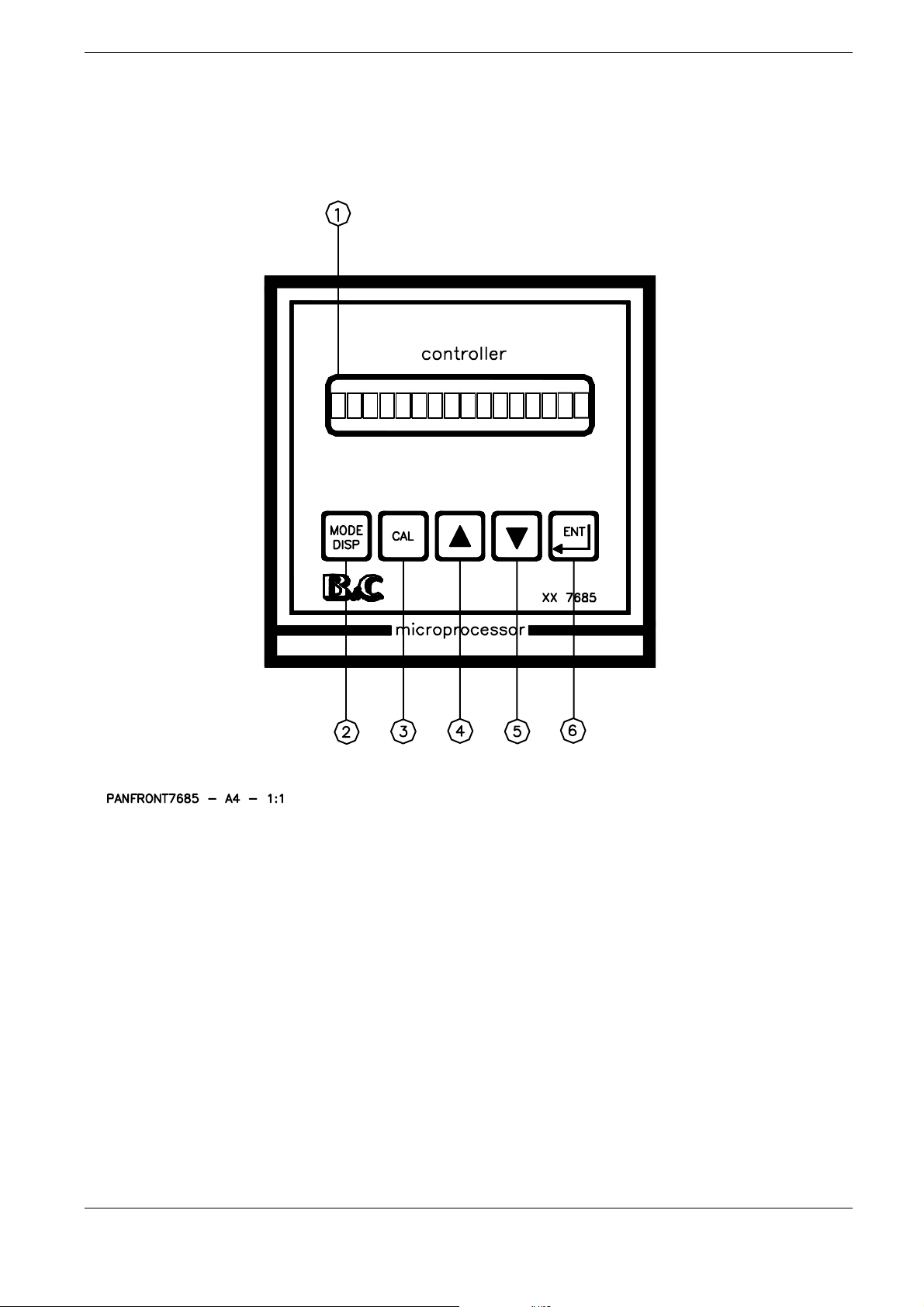
3 OPERATING THE SYSTEM
1. LCD display
electronics
2. Mode-Display key
3. Calibration key
4. Increase key
5. Decrease key
6. Enter key
Fig. 1
Instruction manual - Rev. A - 07/09
- 12 -

B&C Electronics OD 7685.110
3.1 KEYS FUNCTION
KEY FUNCTION
- it allows the operator to go to the next display
- it allows to go back to the main display.
ù
Key “Mode Disp”
§
Key “Cal”
The eventual new parameter values will not be memorized
- it allows the access of calibration sequences
ò
Key “Up”
ç
Key “Down”
£
Key “Ent”
- it allows to increase the displayed parameters
- it allows to choose between different functions
- it allows to decrease the displayed parameters
- it allows to choose between different functions
- it allows to enter the selected data and to return to the main
Display D0
Instruction manual - Rev. A - 07/09
- 13 -

B&C Electronics OD 7685.110
3.2 READOUT SEQUENCES
When the power is turned on, the display will come up with a program and version number, which
will remain on the display for a few seconds.
The display will then change to a display of oxygen concentration and an indication of the status of
control relays. This is the main operating display, and should look like the display below:
·D0·
or
·D0·
or
·D0·
20.00PPM: actual dissolved oxygen value
AL: set-point A state and function LO
ì : deactivated relay
è : the process has reached the set-point and the relay activation is delayed
à : activated relay
BH: set-point B state and function HI
20.0°C: actual temperature value in °C
68°F: actual temperature value in °F
M: manual temperature compensation
MESSAGE MEANINGS
" >>>>> " over range
" <<<<< " under range
"CLEAN CYCLE" the instrument is in AUTO CLEAN function
(relay D on)
"HOLD CYCLE" the instrument is in Hold
Instruction manual - Rev. A - 07/09
OD7685.110 R2.0x
20.00ppmM ìALàBH
20.00ppm 20.0°CM
20.00ppm 68°FM
- 14 -

B&C Electronics OD 7685.110
Press ù to visualize the following display:
D0
xxx%airM ìAL àBH
Dissolved oxygen values in %air (ppm - mg/l mmHg), set point state and function
D0 bis
D1
D2
D3
D4
D5
xxx.x%air xx.x°C
p:xxx sal: xxxxx
TEMP.: xx.x°CM
SA:xxx %air* LO
SB:xxx %air* HI
CLEANING OFF
Dissolved oxygen and temperature values
Barometric pressure and salinity compensation
values
Sample temperature display
Relay A set point and function
Relay B set point and function
Sensor cleaner function
D6
D7
D8
01 xx.xmA/xxx %a
02 xx.xmA/xxx %a
Configuration
Analog Nr 1 output indication
Analog Nr 2 output indication
Access to setup routines
D9
Instruction manual - Rev. A - 07/09
OD7685.110 R2.0x
P/N and release number
- 15 -

B&C Electronics OD 7685.110
3.3 CALIBRATION SEQUENCES
The following procedures will be activable whenever the instrument is not
in the keyboard lock condition.
To unlock the keyboard follows the procedures mentioned in chapter "Configuration".
The following procedures allows the sensors calibration, the set-point and autoclean parameters
programming.
3.3.1 Zero and sensitivity calibration
The instrument is delivered with factory calibration that can be restored by pressing the three keys
ò ç £ as described in the following procedures.
Check the correct setting of the secondary parameters described in D1 display and prepare a zero
dissolved oxygen solution to perform the zero calibration.
The errors messages inform the operator about a possible sensor malfunctioning.
If the zero offset is > 40 mV it is necessary to replace the sensor.
If the sensitivity value is > 250% o < 20% it is necessary to make the sensor maintenance.
·D0· or alternative main display
xxx.x%air 20.0°C
1. § press the key to activate the zero/sens calibration
Zero calibration
This calibration is necessary during:
- first installation of the optical DO system
- first installation of the ATI galvanic cell or after the membrane/electrolyte replacement
The instrument visualizes the zero value first in order to go ahead with the zero calibration or to go to
the next sensitivity calibration.
Immerse the probe in a fresh 2 %, wait for the stabilization and perform the zero calibration as
described below.
x.x mV: actual zero value
Zero: x.x mV
Instruction manual - Rev. A - 07/09
- 16 -

B&C Electronics OD 7685.110
ù to exit and to turn to ·D1·
£ to confirm and to go to the sensitivity calibration
2. § to activate the zero calibration sequence
x.x: zero value from the sensor
CAL Zero: x.x
ù to exit and to turn to ·D1·
ò +ç +£ to turn to the factory calibration
3. £ to end the zero calibration and to go to the sensitivity calibration
MESSAGES MEANING
The calibration has been accepted
Zero> 40 mV
The calibration has not been accepted.
The unit turn to ·D0·.
Sensitivity calibration
The monitor can be calibrated in one of two way, automatic air calibration, or manual calibration.
Automatic air calibration lets the electronics adjust the calibration based on the temperature measured
by the RTD in the sensor and programmed values for altitude, salinity, and relative humidity.
Manual calibration allows the value on the display to be adjusted to a value provided from a secondary
measuring device, usually a portable D.O. unit.
The choice of the method depends of the operator preference.
Instruction manual - Rev. A - 07/09
£ press the key to interrupt the messages and read the new message
Z > 40 mV
The above messages last for 5 minutes.
UPDATE
NO UPDATE
- 17 -

B&C Electronics OD 7685.110
The air calibration is simple and reliable because it uses ambient air as a reference standard, which is
generally stable. However, it requires that the sensor be removed from the tank and allowed to
stabilize at air temperature, which can take 20 minutes.
The manual method allows the sensor to be left in the tank and a portable sensor dropped near it to get
a reference measurement. The monitor can then set to the value measured by the portable.
Note 1:
In case of needing, the user can turn to the factory calibration by pressing simultaneously the keys
ò ç £
The procedure starts after the zero calibration from the following display:
xxx.x: sensitivity value
SENS: xxx.x %
ù to exit and to turn to ·D0·
£ to confirm the actual value and to turn to ·D0·
1. § to access the calibration procedure
(MANUAL)
AUTO (MANUAL): calibration mode
CAL O2:AUTO/air
ù to exit and to turn to ·D0·
2. ò ç to choose the calibration mode
3. £ - to confirm the calibration mode
- to go to the automatic (procedure A) or manual (procedure B) mode.
(procedure A) Automatic sensitivity calibration
- verify the programmed values of barometric pressure and relative humidity;
- turn the salinity value to zero before calibrating (and set the value again after the calibration);
- remove the sensor form the sample;
- verify that the temperature readout is correct.
Instruction manual - Rev. A - 07/09
- 18 -

B&C Electronics OD 7685.110
4A. £ press the key to access the procedure
xxx.x: dissolved oxygen value
A: automatic calibration procedure
ù to exit and to turn to ·D0·
ò +ç +£ to turn to factory calibration
5A. £ to confirm the sensitivity calibration and to turn to ·D0·
(procedure B) Manual sensitivity calibration
Manual calibration allows the operator to simply set the display to a known D.O. concentration
measured by another method.
The sensor must be left in the tank and the D.O. be measured accurately with either a chimical test or a
portable D.O. meter.
The D.O. concentration of the sample must be constant at least for the response time of the sensor.
The procedure starts from the following display::
xxx.x: D.O. measuring value
M: manual calibration
CAL O2: xxx.x A
CAL O2: xxx.x M
ò +ç +£ to turn to factory calibration
4B.
5B. £ - to confirm the sensitivity calibration and to turn to ·D0·
MESSAGES
Instruction manual - Rev. A - 07/09
ù to exit and to turn to ·D0·
ò ç to adjust the D.O. measuring value
FUNCTION
The calibration is accepted.
The unit turns to ·D1· after 1”
UPDATE
- 19 -

B&C Electronics OD 7685.110
Error messages
sensitivity > 250.0 %
sensitivity < 20.0 %
The above messages last for 5 minutes.
£ press the key to stop the message
The calibration is not accepted.
The unit turns to ·D1·.
S > 250.0 %
S < 20.0 %
NO UPDATE
3.3.2 Secondary parameters calibration
This procedure allows to set the:
- barometric pressure;
- salinity
- relative humidity.
Those values will be used by the unit to access the compensation table.
1. ù press one time the key to go to
·D1·
xxx: barometric pressure value
xxxxx: salinity value
2. § to access the calibration procedure
Barometric pressure calibration
xxx mmHg: barometric pressure value
Instruction manual - Rev. A - 07/09
p:xxx sal: xxxxx
CAL p: xxx mmHg
- 20 -

B&C Electronics OD 7685.110
ù to exit and to turn to ·D1·
3. ò ç to adjust the barometric pressure value
4. £ to confirm the value and to go to the salinity calibration
MESSAGES FUNCTION
The new value is memorized
UPDATE
Salinity calibration
CAL sal:xxxxxppm
xxxxxppm: salinity value
ù to exit and to turn to ·D1·
5. ò ç to adjust the salinity value
6. £ to confirm the value and to go to the relative humidity calibration
MESSAGES
FUNCTION
The new value is memorized
UPDATE
Relative humidity calibration
CAL RH: xxx%
xxx%: relative humidity value
ù to exit and to turn to ·D1·
Instruction manual - Rev. A - 07/09
- 21 -

B&C Electronics OD 7685.110
7. ò ç to adjust the relative humidity value
8. £ to confirm and to turn to ·D1·
MESSAGES FUNCTION
The new value is memorized
UPDATE
3.3.3 Temperature calibration
The temperature measurement function is factory calibrated and normally will not require field
adjustment.
However the temperature display can be calibrated using a single point calibration.
To calibrate, simply immerse the sensor in a beaker and allow the sensor to stabilize at the water
temperature. Use a precision thermometer accurate to 0.1 °C to measure the water temperature, and
compare to the meter display for the calibration.
In case of needing it is possible to turn to the factory calibration by pressing simultaneously the keys
ò ç £ as described in this section of the manual.
1. ù press two times from D0 to reach the following display
·D2· sample temperature value in °C (°F)
M: manual value
2. § to access the temperature or the manual temperature adjustment
(°F)
>>>>>>: over range value
ù to exit and to turn to ·D1·
Temp: 20.0°CM
CAL T 20.0°C
ò +ç +£ to turn to factory calibration
3. ò ç to adjust the temperature value of the sample
Instruction manual - Rev. A - 07/09
- 22 -

B&C Electronics OD 7685.110
4. £ to confirm and to go to the manual temperature adjustment
(68.0°F)
22.0°C (68.0°F): manual temperature value
CAL T.M: 22,0°C
ù to exit and to turn to ·D1·
5.
6.
MESSAGES FUNCTION
The calibration is accepted.
Messaggi di errore
£ press the key to interrupt the message
The calibration is not accepted.
The unit turn to ·D1·
ò ç to adjust the manual temperature value
£ to confirm the manual temperature value and to turn to ·D1·
UPDATE
zero > 2.00 °C (3.6 °F)
display is visualized for 5 minutes
z > 2.00°C
NO UPDATE
3.3.4 Set point A and B
The set-point B procedure is same as set-point A procedure, in this way the user will follow the next
description just considering (SB) instead of (SA) and ·D4· instead of ·D3· .
The procedures allow to:
- adjust the set-point values;
- set the hysteresis value;
- set the delay value.
Instruction manual - Rev. A - 07/09
- 23 -

B&C Electronics OD 7685.110
1. ù press three times the key from D0 to reach ·D3· (set A)
press four times the key from D0 to reach ·D4· (set B)
·D3·
(·D4·) (SB)
SA: set-point A parameters
(SB: set-point B parameters)
xxx %air: set point value
à : set-point status (activated relay)
LO: function minimum (HI))
2. § to access the set-point, hysteresis, delay calibration
Set point calibration
SA: set-point A parameters
xxx.x: set-point value
SA:xxx %air àLO
CAL SA S:xxx.x
ù to exit and to turn to ·D3/D4·
3. ò ç to insert the set-point value
4. £ to confirm and to go to the next set point parameter calibration.
3.3.5 On/Off parameters
xx.x: actual hysteresis value
1. ò ç to insert the hysteresis value
ù to exit and to turn to ·D3/D4·
CAL SA I: xx.x
2. £ to confirm and to go to the delay value insertion
Instruction manual - Rev. A - 07/09
- 24 -

B&C Electronics OD 7685.110
5.0s: actual delay value
ù to exit and to turn to ·D3/D4·
3. ò ç to insert the delay value
4. £ to confirm the delay value and to turn to ·D3/D4·
MESSAGES FUNCTION
The calibration is accepted.
CAL SA D: 5.0s
UPDATE
3.3.6 Auto clean parameters
1. ù press five times the key from D0 to reach ·D5·
·D5· (MANUAL CLEAN/AUTO CLEAN)
2. § to access the auto clean parameter calibration
Manual function (MANUAL CLEAN)
(START)
WAITING: the unit is waiting for the clearing cycle start
CLEANING OFF
CLEAN C. :WAITING
ù to exit and to turn to ·D5·
3A. ò ç to select START or WAITING
4A. £ to confirm the selected parameter
Instruction manual - Rev. A - 07/09
- 25 -

B&C Electronics OD 7685.110
If START has been selected, the unit turn to ·D0· and a cleaning cycle
will start.
If WAITING has been selected, the unit will turn to ·D5·
Automatic function (AUTO CLEAN)
xx.xh: waiting time (hours) before next cycle
NEXT CYCLE:xx.xh
ù to exit and to turn to ·D5·
ò + ç + £ to turn to the factory calibration
3B. £ press the key to visualize the waiting time before the next cleaning cycle
(START)
WAITING: the unit is waiting for the new cleaning cycle
ù to exit and to turn to ·D5·
4B. ò ç to select START o WAITING
£ to confirm the selected parameter
5B.
xx.xh: repetition time (hours) of the cleaning cycle
CLEAN C. :WAITING
If START has been selected, the unit turn to ·D0· and a cleaning cycle
will start. (the automatic cycle parameter will not be changed).
If WAITING has been selected, the unit will go to the repetition time
calibration.
REPETITION:xx.xh
ù to exit and to turn to ·D5·
6B. ò ç to set the repetition time
Instruction manual - Rev. A - 07/09
- 26 -

B&C Electronics OD 7685.110
7B. £ to confirm the repetition time and to turn to ·D5·
MESSAGES FUNCTION
The calibration is accepted.
Note:
The unit will turn to the previous display if any key has not been used during the calibration procedure
within 5 minutes.
The new data will be not memorized.
UPDATE
3.3.7 Visualizations
The D6 and D7 display allow the analog output visualization.
The D8 display allows to visualize the configuration parameters and to change the configuration under
the password protection.
The D9 display allows the visualization of the P/N and the installed software release.
ù press six times the key from D0 to reach ·D6·
·D6·
01: analog output Nr 1
xx.xmA : actual output current value
xxx %a (100°C): actual D.O. measuring value
01 xx.xmA/xxx %a
ù press the key to go to ·D7·
·D7·
02: analog output Nr 2
xx.xmA : actual output current value
xxx %a (100°C): actual temperature measuring value
02 xx.xmA/xxx %a
1. ù press eight times the key from to reach ·D8·
·D8· Configuration dispaly
Instruction manual - Rev. A - 07/09
Configuration
- 27 -

B&C Electronics OD 7685.110
§ to access the keyboard locked/unlocked selection.
ù press nine times the key from D0 to reach ·D9·
·D9· P/N and software release
OD7685.110 R2.0x
ù press the key to turn to ·D0·
3.3.8 Configuration
1. ù press eight times the key from D0 to reach the display ·D8·
·D8·
2. § to access the configuration procedures
The following keys will be active in the configuration menu:
ù to exit and to turn to ·D8·
3. ò ç to change or to select the parameters
4. £ to confirm the new selection and go to the next parameter configuration.
The unit will display the following message:
Configuration
UPDATE
3.3.9 Keyboard locked/unlocked
UNLOCKED: keyboard is locked
LOCKED: keyboard in unlocked
Instruction manual - Rev. A - 07/09
KB UNLOCKED
- 28 -

B&C Electronics OD 7685.110
3.3.10 LCD contrast
The user can select 7 level of LCD contrast.
LCD CONTRAST: 4
3.3.11 Main display
The user can select one of the following main display.
Disp.: DO + SET
Disp: DO + TEMP
3.3.12 Temperature measuring unit
The user can select the unit in °C or °F
Temp. Unit: °C
Temp. Unit: °F
3.3.13 Access number
Access nbr request
Note:
If the user will use a wrong access nbr, it will be possible to visualize the configuration parametes but
not make changes.The following message will appear for few seconds.
Inhibition of the calibration
Access Nr: 0
Cal Inhibition
Instruction manual - Rev. A - 07/09
- 29 -

B&C Electronics OD 7685.110
3.3.14 Measuring unit
%air: scale in % air
ppm: scale in ppm
mg/l: scale in mg/l
mmHg: scale in mm mercurium
O2 Scale: %air
3.3.15 Software filter LARGE
LARGE S RT: 2.0s
Large filter response time
3.3.16 Software filter SMALL
SMALL S RT:10.0s
Small filter response time
3.3.17 Input related to the analog output Nr 1
%air, ppm, mg/l, mmHg o °C
CAL OUT1: %air
3.3.18 Analog output Nr1 parameters
0/20mA (4/20mA)
P2: end of the scale
Note:
if the P2 value is lower than P1 value, the output will be reverse.
CAL OUT1: 0/20mA
CAL P1: xxx.x%air
CAL P2: xxx.x%air
P1: begin of the scale
xxx.x%air: input value
corresponding to 0 or 4 mA
xxx.x%air. : input value
corresponding to 20 mA
3.3.19 Input related to the analog outpt Nr 2
%air, ppm, mg/l, mmHg o °C
CAL OUT2: %air
Instruction manual - Rev. A - 07/09
- 30 -

B&C Electronics OD 7685.110
3.3.20 Analog output Nr 2 parameters
0/20mA (4/20mA)
P2: end of the scale
xxx.x%air: input value corresponding
to 20 mA
Note:
if the P2 value is lower than P1 value, the output will be reverse.
CAL OUT2: 0/20mA
CAL P1: xxx.x%air
CAL P2: xxx.x%air
P1: begin of the scale
xxx.x%air: input value
corresponding to 0 or 4 mA
3.3.21 Set-point A function
SET A F.: LO
LO: Minimum
HI: Maximum
3.3.22 Set-point B function
SET B F.: LO
LO: Minimum
HI: Massimo
3.3.23 Cleaning function
CAL CF:DISABLED
DISABLED: function disabled
MANUAL: manual function
AUTO: automatic function
3.3.24 Number of clearing cycle
N. CICLI: 4
Actual cycle numbers
3.3.25 Compressor charge time (relay D off)
CHARGE T.: 2.00”
Instruction manual - Rev. A - 07/09
Time in seconds
- 31 -

B&C Electronics OD 7685.110
3.3.26 Compressor discharge time (relay D on)
DISCHARGE T.:3.0”
Time in seconds
3.3.27 Hold
HOLDING T: 3.0’
Time in minutes
3.3.28 Access number
Change Nr: NO
Insert the new password
Confirm the new password
If the new password is not confirmed the uni twill send the message 'NO UPDATE'.
New Nr: 0
Confirm Nr: 0
NO : password changing not requested
YES: password changing requested
£ press the key few times to verify the configuration parameters.
Instruction manual - Rev. A - 07/09
- 32 -

B&C Electronics OD 7685.110
4 INSTALLATION
4.1 PHYSICAL INSTALLATION
The unit may be installed close to the points being monitored in a suitable switch board or in a
water-tight enclosure for field applications.
The enclosure is designed for panel-mounting. It should be mounted on a rigid surface, in a position
protected from the possibility of damage or excessive moisture or corrosive fumes.
For the Auto-clean application the unit is installed in the enclosure containing the autoclean system.
4.2 ELECTRICAL INSTALLATION
All connections within the controller are made on detachable terminal strips located on the rear side.
(fig. 2)
All power and output-recorder connections are made at the 13 pin terminal strip, while input signal
connections are made at the 12 pin terminal strip.
The electrical installation consists of:
Connecting the power
- connect ground to terminal 4
- connect ac power to 1 - 2 terminals if power voltage is 110 V
- connect ac power to 1 - 3 terminals if power voltage is 220 V
if 091.404 option is installed, connect 24 Vac to 1-3 terminals
Warnings:
- power the device by means of an isolation transformer
- avoid mains-voltage from an auto-transformer
- avoid mains voltage from a branch point with heavy inductive loads
- separate power supply wires from signal ones
- check the mains voltage value
4.2.1 Connecting the optical DO probe with the built in temperature sensor
- connect the white wire to the terminal 17 marked V-
- connect the green wire to the terminal 18 marked V+
- connect the red wire to the terminal 22 marked IN+
- connect the black wire to the terminal 21 marked IN-
- connect the brown wire to the terminal 23 marked t1
- install a jumper between terminals 24 marked t2 and 25 marked t3
The connection of the probe is a critical part of the installation:
- avoid cable interruptions
- keep the cable of the probe far from power cables
Instruction manual - Rev. A - 07/09
- 33 -

B&C Electronics OD 7685.110
4.2.2 Connecting the relays
The output connections referred to set-point 1 and set-point 2 are made at terminal strip and they
consist of two independent SPDT relays corresponding
to Regulator A and Regulator B.
The output connections referred to Auto-Clean consist of two SPST relays corresponding to
autoclean C/D.
Control relay "A"
terminal 6 marked C : common contact
terminal 5 marked NO : normal open contact
terminal 7 marked NC : normal closed contact
Control relay "B"
terminal 9 marked C : common contact
terminal 8 marked NO : normal open contact
terminal 10 marked NC : normal closed contact
Relay "C" (Autoclean - Compressor)
terminal 12 marked C : common contact
terminal 11 marked NO : normal open contact
Relay "D" (Autoclean - Solenoid)
terminal 12 marked C : common contact
terminal 13 marked NO : normal open contact
4.2.3 Connecting the analog output
A dual current output for a remote recorder or P.I.D. regulators is available on terminals 14-15-16.
Connect to terminals 14-16 for the 1st channel output.
Connect to terminals 15-16
Series connection is required for driving more loads having a total input Resistance lower than 600 ohm.
Output current is 0/20 or 4/20 mA isolated.
for the 2nd channel output.
4.2.4 Checking
Before connecting the system to the power supply:
- check that all cables are properly fastened to prevent strain on the connections
- check that all terminal-strip connections are mechanically and electrically sound
Instruction manual - Rev. A - 07/09
- 34 -

B&C Electronics OD 7685.110
5 PREVENTIVE MAINTENANCE
Controller
Quality components are used to give the controller a high reliability.
The frequency of such maintenance depends on the nature of each particular application.
As in any electronic equipment, the mechanical components, such as switches, relays and
connectors, are the most subject to damage.
- check for damage of the electrolytic capacitors if the meter is exposed to temperatures above
80 degree C.
- check for damage in all the electronic components if the meter is subjected to excessive voltage
- check for damage of the electronic and mechanical components if the meter is dropped
- repeat periodically the pre-operation check
- check that all the connections are free from moisture and contamination
Disconnect the power supply to the monitor before performing the following procedures:
- Use moisture free air and blow out the interior of the case and terminal board connections as
necessary
- Inspect the printed circuit boards for dirt and corrosion; clean as necessary and blow dry
- Tighten all the terminal-board connections and mounting hardware
- Replace the front panel circuit board or the base circuit board
Sensor
See the instruction manual of the sensor.
Instruction manual - Rev. A - 07/09
- 35 -

B&C Electronics OD 7685.110
CONNECTIONS
1. 2 110 Vac power supply
1. 3 220 Vac power supply
4. Ground
5. 6 A relay N.O. contacts
6. 7 A relay N.C. contacts
8. 9 B relay N.O. contacts
9. 10 B relay N.C. contacts
11. 12 C relay N.O. contacts
12. 13 D relay N.O. contacts
14. Analog output Nr 1 (+)
15. Analog output Nr 2 (+)
16. Analog output Nr 1 and Nr 2 (-)
17. Input W (white wire)
18. Input (green wire)
21. Input BL (black wire)
22. Input R (red wire)
23. Input BR (brown wire)
24.25. Jumper
Fig. 2
Instruction manual - Rev. A - 07/09
- 36 -

B&C Electronics OD 7685.110
DIMENSIONS
electronics
DRILL PLAN
Fig. 3
Instruction manual - Rev. A - 07/09
- 37 -

B&C Electronics OD 7685.110
WARRANTY CERTIFICATE
1) Your product is covered by B&C Electronics Warranty for 5 years from the date of
shipment. In order for this Warranty to be valid, the Manufacturer must determine that the
instrument failed due to defective materials or workmanship.
2) The Warranty is void if the product has been subject to misuse and abuse, or if the damage
is caused by a faulty installation or maintenance.
3) The Warranty includes the repair of the instrument at no charge. All repairs will be
completed at the Manufacturer’s facilities in Carnate, Italy.
4) B&C Electronics assumes no liability for consequential damages of any kind, and the buyer
by accepting this equipment will assume all liability for the consequences of its use by the
Customer, his employees, or others.
REPAIRS
1) In order to efficiently solve your problem, we suggest You to ship the instrument along
with the Technical Support’s Data Sheet (following page) and a Repair Order.
2) The estimate, if requested by the Customer, is free of charge when it is followed by the
Customer confirmation for repair. As opposite, if the Customer shall not decide to have the
instrument repaired, he will be charged to cover labor and other expenses needed.
3) All instruments that need to be repaired must be shipped pre-paid to B&C Electronics. All
other expenses that have not been previously discussed will be charged to Customer.
4) Our Sales Dept. will contact You to inform You about the estimate or to offer you an
alternative, in particular when:
- the repairing cost is too high compared to the cost of a new instrument,
- the repairing results being technically impossible or unreliable
5) In order to quickly return the repaired instrument, unless differently required by the
Customer, the shipment will be freight collect and through the Customer’s usual forwarder.
B&C Electronics Srl - Via per Villanova 3 - 20040 Carnate (MB) - P.IVA 00729030965
Tel (+39) 039 63 1721 - Fax (+39) 039 607 6099 - info@bc-electronics.it - www.bc-electronics.it
Instruction manual - Rev. A - 07/09
- 38 -

B&C Electronics OD 7685.110
TECHNICAL SUPPORT
Data sheet
In case of damage, we suggest You to contact our Technical Support by email
or phone. If it is necessary for the instrument to be repaired, we recommend to
photocopy and fill out this data sheet to be sent along with the instrument, so to
help us identifying the problem and therefore accelerate the repairing process.
□ ESTIMATE □ REPAIR
COMPANY NAME
ADDRESS ZIP CITY
REFER TO MR./MISS. PHON E
MODEL S/N DATE
Please check the operator’s manual to better identify the area where the problem seems to be
and please provide a brief description of the damage:
□ SENSOR □ ANALOG OUTPUT
□ POWER SUPPLY □ SET POINT
□ CALIBRATION □ RELAY CONTACTS
□ DISPLAY □ PERIODICAL MALFUNCTIONING
¾ DESCRIPTION
................................................................................................................................................................
................................................................................................................................................................
................................................................................................................................................................
................................................................................................................................................................
................................................................................................................................................................
................................................................................................................................................................
................................................................................................................................................................
................................................................................................................................................................
Instruction manual - Rev. A - 07/09
- 39 -

B&C Electronics OD 7685.110
N O T E S
Instruction manual - Rev. A - 07/09
- 40 -
 Loading...