


CERT. N. 9115 BCEL
OPERATOR’S MANUAL
UNI EN ISO 9001:2000
OD 545.2 - OD 565.2
DIGITAL DISSOLVED OXYGEN
CONTROLLERS
Rev. A – Valid from S/N 28421
Input: from polarographic cells
Scales: 0/19.99 PPM
0/199.9 % O2
0/199.9 % air saturation
0/199.9 mmHg
Power supply: 110/220 Vac
B&C Electronics Srl – Via per Villanova 3 – 20040 Carnate (Mi) – Italy P.IVA 00729030965
Tel +39 039 63 1721 – Fax +39 039 607 6099 bc@bc-electronics.it - www.bc-electronics.it

B&C Electronics OD 545.2 – OD 565.2 - Rev. A
Index
1 GENERAL .................................................................................................................................... 3
2 PRINCIPLES ................................................................................................................................ 3
3 FUNCTIONAL DESCRIPTION .................................................................................................. 4
4 PHYSICAL DESCRIPTION ........................................................................................................ 8
5 SPECIFICATIONS....................................................................................................................... 9
6 PHYSICAL INSTALLATION................................................................................................... 10
7 ELECTRICAL INSTALLATION .............................................................................................. 11
7.1 Connecting the power........................................................................................................ 11
7.2 Connecting the cell (probe) .............................................................................................. 13
7.3 Connecting the microtransmitter ....................................................................................... 13
7.4 Connecting alarms, pumps, valves .................................................................................... 13
7.5 Connecting a recorder........................................................................................................ 14
7.6 Connecting the RTD.......................................................................................................... 14
7.7 Checking............................................................................................................................ 14
8 OPERATING THE SYSTEM .................................................................................................... 15
8.1 Pre-operation check ........................................................................................................... 15
9 NORMAL OPERATION............................................................................................................ 15
10 CALIBRATING THE CONTROLLER ..................................................................................... 16
10.1 Electric zero....................................................................................................................... 16
10.2 Zero cell calibration........................................................................................................... 16
10.3 Slope calibration ................................................................................................................ 16
10.4 Polarization voltage of sensor............................................................................................ 17
11 PREVENTIVE MAINTENANCE.............................................................................................. 18
11.1 Controller........................................................................................................................... 18
11.2 Sensor ................................................................................................................................ 18
12 TROUBLESHOOTING GUIDE ................................................................................................ 19
- 2 -

B&C Electronics OD 545.2 – OD 565.2 - Rev. A
1 GENERAL
This manual applies to the OD 545.2 and OD 565.2 digital controllers.
It explains the purpose of the equipment, describes the components of the chain and the procedures for
installing the equipment, operating it and calibrating it.
Some suggestions are also given for its maintenance.
2 PRINCIPLES
In a polarographic cell, if a constant tension is applied to the electrodes, the reduction of the oxygen
ions on the cathode generates a current proportional to the oxygen's partial pressure.
The intensity of the current produced at a constant temperature and at a given oxygen pressure
depends on the quantity and composition of the electrolyte, the cathode's area and the sample's state.
Response time depends on the electrolyte's and diaphragm’s characteristics.
The value of the applied voltage to the anode is chosen in a way that only oxygen can react.
In absence of oxygen, the current produced is not exactly zero.
In fact, impurities and other factors generate a "dark current" which can be offset by the amplifier.
The electrode consumes the oxygen diffused through the permeable membrane (PTFE) and the
electrolyte's film, therefore a concentration gradient is established between cathode and sample; the
electrodes with a big cathode, with a high output current, consume a lot of oxygen and are more
sensitive to the sample's flow and therefore request a large flow and an adequate stirring of the sample.
The temperature dependence of the output current is compensated by the automatic temperature
compensation of the meter.
- 3 -

B&C Electronics OD 545.2 – OD 565.2 - Rev. A
3 FUNCTIONAL DESCRIPTION
This system provides a digital readout of the dissolved oxygen of aqueous solutions.
In order to satisfy the many requests of such measurements, two types of amplifiers with different
ranges have been designed:
The model OD 565.2 for industrial applications and the model OD 545.2 for fermentation.
The mod. OD 565.2 features:
- selectable ranges in PPM, % air, % O2, mmHg.
- auto/manual temperature compensation
- temperature and temperature coefficient readout
- adjustable temperature coefficient
- polycarbonate membrane panel
The mod. OD 545.2 features:
- 0/200.0 % AIR saturation scale
- automatic temperature compensation
A basic dissolved oxygen monitoring system consists of two elements:
a monitor unit, and a probe or O2 cell.
The system can be expanded by adding accessories for field applications, recorders, secondary
regulators, proportional regulators, special probes and temperature probes to suit particular
applications.
The controller contains electronic circuits to control the operation of the entire system.
It provides a digital readout of dissolved oxygen on a 3 1/2 digit display.
There is included an internal circuitry for controlling two alarms, valves, pumps etc.
Set-points are independent and programmed by a front-panel control to trigger at any level within the
range of the meter.
Red LEDs on the panel indicate if the measured value is below the set point A level, or if it is above
the set point B level.
Red LEDs also indicate the switching of corresponding relays.
The controller provides an output of 0/20 mA - 4/20 mA selectable by rear switch (on request 0/10 V
or others).
The output is proportional to the meter reading, for driving a recorder, remote readout or regulators
having an isolated input (not grounded).
Zero and slope are adjusted by trimmers 2 and 3 on the front panel.
- 4 -
B&C Electronics OD 545.2 – OD 565.2 - Rev. A
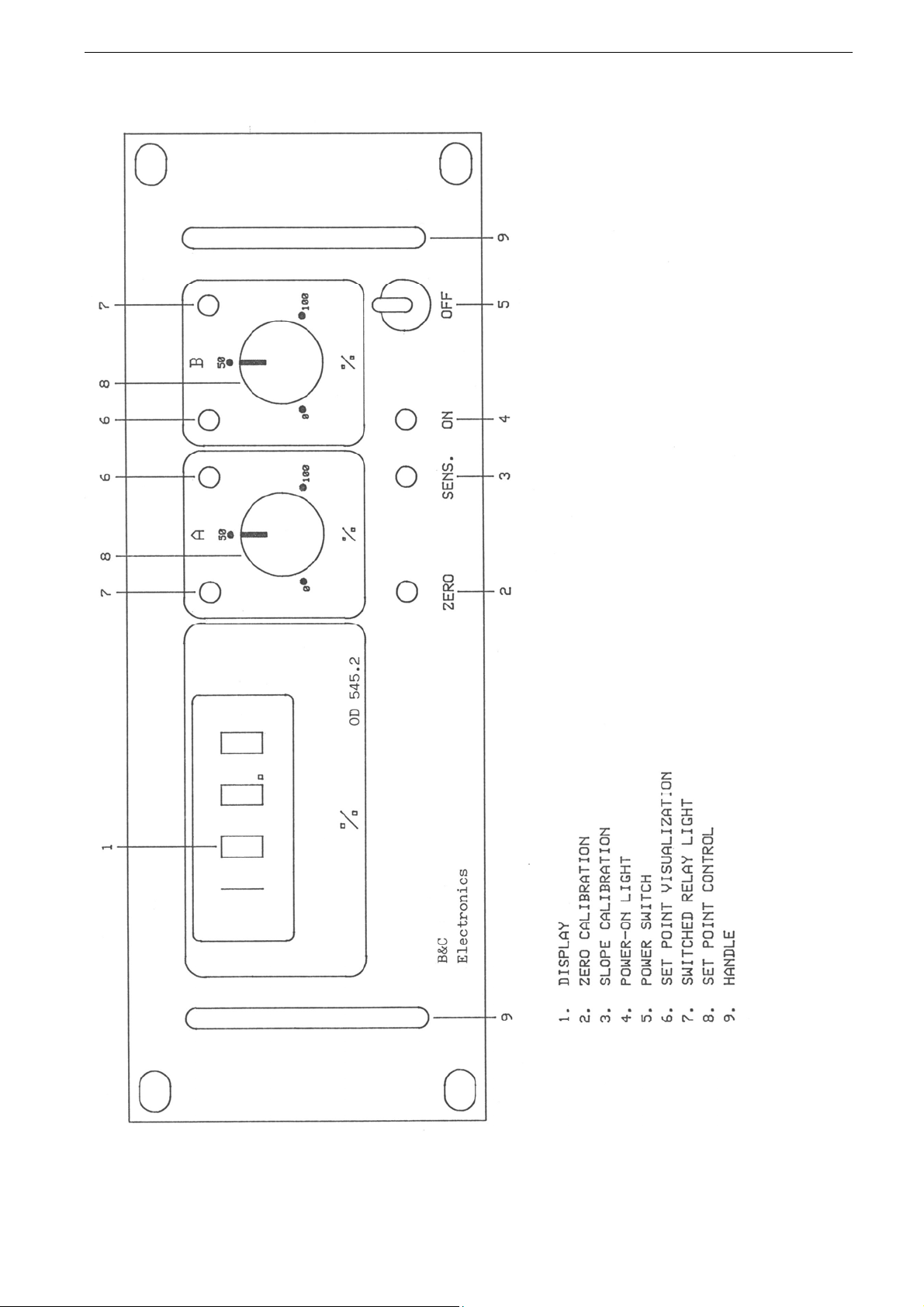
Fig. 1
- 5 -
B&C Electronics OD 545.2 – OD 565.2 - Rev. A
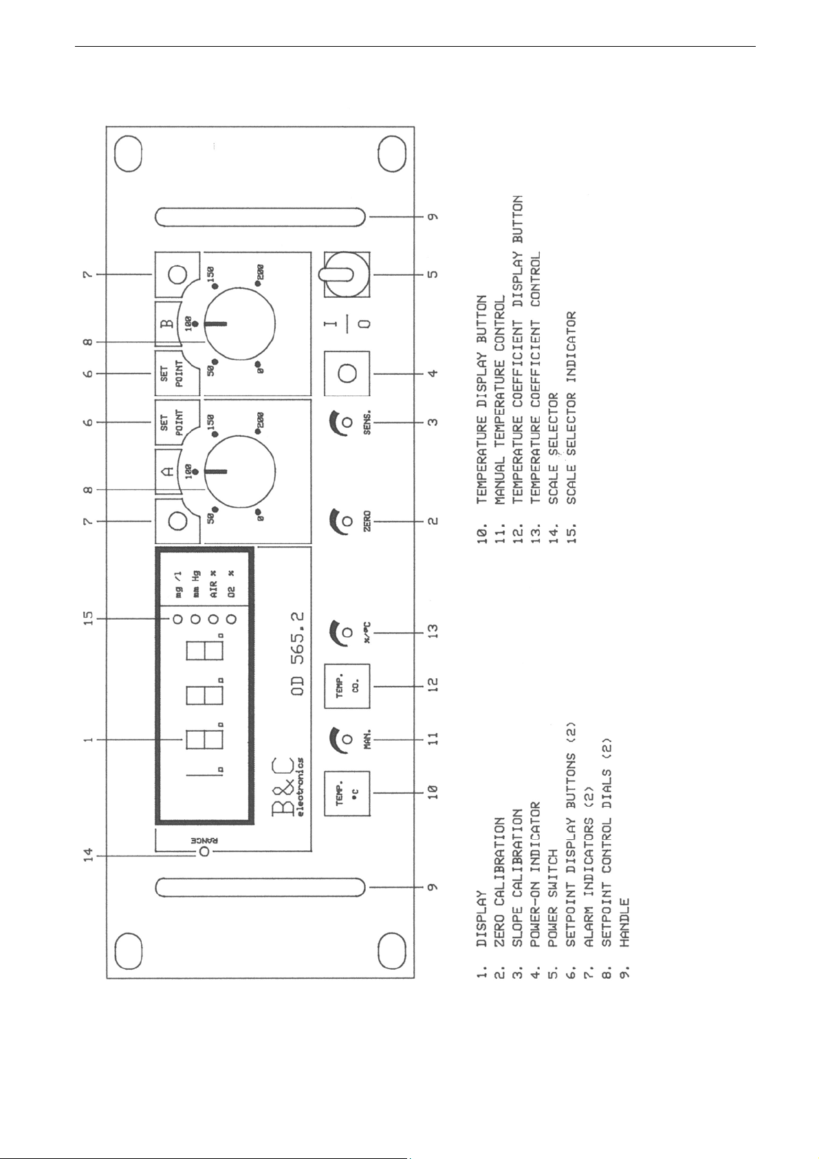
Fig. 2
- 6 -

B&C Electronics OD 545.2 – OD 565.2 - Rev. A
The following features are available:
- the set point value is visualized by pushing the button 6 on the front panel
- the switching function of relay is inverted by rear switches marked min/MAX
- the regulators have a delay action 0 to 5 seconds by rear trimmers marked DEL A and DEL B
- the B regulator, as an " option ", can be supplied as a " window alarm " working over the set
point A with the delay action included.
- automatic temperature compensation is carried out by means of a 3 wire RTD Pt 100.
- the input of meters is both by electrodes (probes) or by amplified probes (by microtransmitter).
This special probe is completely waterproof and contains the measuring O2 cell and a microtransmitter
which allows a normal electrical cable to be used to receive the signal. With this technical solution, it
is possible to make considerably long connections between the measuring point and the controller
without signal delay or interference.
As a result, fewer additives are consumed and a greater precision of regulation is obtained.
Furthermore, the coupling of the instrument and the probe by means of a 4 wire cable, is protected
against connection errors. (a 7 wire cable is needed when Pt 100 thermo compensator is installed)
Therefore, the installation of the measuring and regulating link can be carried out by non-specialized
staff.
In the model OD 565.2 the digital temperature readout is obtained by pushing a button 10 on front
panel, as measuring and controlling functions of the instrument are not altered.
The digital temperature factor readout is obtained by pushing a button 12.
The value of the temperature factor is adjusted by the trimmer 11.
The scale is chosen by the selector 14.
- 7 -

B&C Electronics OD 545.2 – OD 565.2 - Rev. A
4 PHYSICAL DESCRIPTION
The controller enclosure is designed for surface or panel mounting.
It consists of an anodized aluminium front panel and an epoxy-coated metallic case, to ensure the
maximum anticorrosion characteristics.
(The model OD565.2 has a polycarbonate membrane on the front panel).
However a mounting in a splash proof board is suggested for field applications.
The figures 3 and 4 show the physical details, dimensions and drill plan of this case.
Connections to power supply, loads, recorder, RTD, electrodes/probe are carried out by means of a
detachable terminal block on the rear side.
Fig. 3
- 8 -

B&C Electronics OD 545.2 – OD 565.2 - Rev. A
5 SPECIFICATIONS
Voltage: 110/220 Vac +/-10 % 50/60 Hz
Input: from polarographic O2 cell
from microtransmitter 080610.2
Output : 0/20 – 4/20 mA dc selectable, nonisolated, 300 Ω max.
Scales OD545.2: 0/199.9 % AIR saturation
Scales OD565.2: 0/19.99 PPM
0/199.9 AIR saturation
0/199.9 % O2
0/199.9 mmHg
Zero: adjustment +/- 15%
Slope: fine adjustment +/- 20%
coarse adjustment
Temperature: 0/50 °C
Cell current in air: 0.030 µA
Temp. comp.: automatic 0/50 °C
Temp. coeff.: 0 to 6 %/K (OD 565.2)
2.3 %/K at 20 °C (others on request) (OD 545.2)
Temp. sensor: RTD Pt100
Temp. readout: 0/100°C (OD 565.2)
Regulators: +/- 0.25% hysteresis (others as requested)
Switching time: < 0.5 s
Regulators delay: 0 to 5 s
Relay contacts: 5 A 220 V resistive load
Fuse : 80 mA T (110 V) 32 mA T (220 V)
Power: 3 VA max
Weight: 1.014 kg
Size: 241 x 89 x 157 mm
Option 091.113 galvanic cell input
Option 091.363 isolated output
Option 091.401 24 Vac power supply
Option 091.201 window B regulator
- 9 -

B&C Electronics OD 545.2 – OD 565.2 - Rev. A
6 PHYSICAL INSTALLATION
The controller may be installed close to the points being monitored, or it may be located some distance
away in a control area.
For a distance between sensor (cell/probe) and controller greater than 30 feet the microtransmitter
probe is suggested to avoid signal delay and interferences.
The enclosure is designed for panel-mounting. It should be mounted on a rigid surface, in a position
protected from the possibility of damage or excessive moisture or corrosive fumes.
Immersion probes have a PVC ring to adjust the depth of the cell into the liquid to be tested. Probes
may be fastened by hangers with 36 mm. hole.
The cable from the probe must be protected by a sheath and not installed near to power cables.
Interruption on cables must be avoided or carried out by high insulation terminals.
When installing the cell it is suggested to follow the specific instructions given by the sensor’s
manufacturer.
- 10 -
Fig. 4

B&C Electronics OD 545.2 – OD 565.2 - Rev. A
7 ELECTRICAL INSTALLATION
The electrical installation consists of:
- connecting the power supply to the meter
- connecting the cell or the probe to the meter
- connecting alarms, pumps, valves if necessary
- connecting the monitor output to the recorder or similar devices if required
- connecting other optional accessories (RTD P.I.D. regulators)
All connections within the controller are made on terminal strips (detachable) located on the rear side.
All power and output-recorder connections are made at the 16 pin terminal strip, while input signal
connections are made at the 8 pin terminal strip.
7.1 CONNECTING THE POWER
- connect ground to terminal 1
- connect ac power to 2 and 3 terminals if power is 110 V
- connect ac power to 2 and 4 terminals if power is 220 V
- use 32 mA T fuse for 220 V
- use 80 mA T fuse for 110 V
(connect 24 Vac power to 2 and 4 terminals if option 091.403 is installed)
WARNINGS:
- power the device by means of an isolation transformer
- avoid mains voltage from an auto-transformer
- avoid mains voltage from a branch point with heavy inductive loads
- separate power supply wires from signal ones
- control the mains voltage value
- it is necessary that all ground terminals of each component of the system should be connected
together to a sure ground.
- 11 -

B&C Electronics OD 545.2 – OD 565.2 - Rev. A
Fig. 5
- 12 -

B&C Electronics OD 545.2 – OD 565.2 - Rev. A
7.2 CONNECTING THE CELL (PROBE)
Electrode cabling is a critical part of the whole system.
- use a low noise coax cable on overall length between sensor and input terminals of the meter
- avoid interruption on the cable if a coax connector and a high insulation terminal strip are not
available
- keep the cable away from power wires on the overall length
- use microtransmitter in field applications for distance longer than 30 feet between the electrode
and the controller.
- connect the cathode (Pt) to the terminal 30 marked Pt
- connect the anode (Ag) to the terminal 31 marked POL
- connect the shield to the terminal 28 marked 0
Electrodes supplied by B&C Electronics have wires marked for the right connection to the meter.
7.3 CONNECTING THE MICROTRANSMITTER
The controller may operate with signal by microtransmitter mod. 080610.2.
Follow the specific instructions for connections.
7.4 CONNECTING ALARMS, PUMPS, VALVES
The output connections are made at terminal strip and they consist of two independent relay contacts
corresponding to regulator ""A" and regulator "B".
Regulator ''A''
terminal 8 marked C : common contact
terminal 9 marked NO : normal open contact
terminal 10 marked NC : normal closed contact
Regulator ''B''
terminal 5 marked C : common contact
terminal 6 marked NO : normal open contact
terminal 7 marked NC : normal closed contact
To provide an ac-line voltage at the relay commons, install jumpers from the ac power terminal 2 to
the concerned relay commons marked C.
Connect one side of an external line-operated device to the terminal NO/NC according to the
requirements of the device, and connect the other side of the device to the line terminal 3 (110 V) or 4
(220 V).
The device may be powered by an external independent line following the above procedure.
An independent line is suggested if the device consists in a high inductive load.
Remember that relay switching inverted by installing jumpers from terminal 12 to 13 (reg. B) and
from 13 to 14 (reg. A).
Also, the action of relay "B" may be delayed 0 to 5 sec by the trimmer marked DEL B. (rear side)
- 13 -

B&C Electronics OD 545.2 – OD 565.2 - Rev. A
7.5 CONNECTING A RECORDER
A current output for a remote recorder or P.I.D. regulators is available on terminals 13-14.
Connect the recorder "high" to terminal "14" and connect the recorder low to terminal "13".
Series connection, following the signal's polarity, is required for driving more loads having a total
input resistance lower than 300 Ω. Output drives ground-isolated loads only. Most recorders fulfil this
requirement but it is recommended to control it.
7.6 CONNECTING THE RTD
The meters have the automatic temperature compensation carried out by means of RTD Pt100.
The temperature sensor, if not included in the electrode, has to be installed in the same solution being
measured, close to the electrode/probe.
The jumpers from 22 to 23 and 24 to 25 terminals keep in action the internal temperature
compensation adjusted at 20 °C.
To operate the automatic temperature compensation, remove the two jumpers and connect the RTD as
shown in Fig. 5.
A three wire connection is suggested to achieve an accurate compensation over a long distance
between the electrode and the controller.
- connect the end of RTD to terminal 23
- connect the common end of the RTD to terminal 24
- connect the common end of the RTD to terminal 25
- The 3-wire cable must not be interrupted on the overall length.
If an extension is needed, the cable must be fastened to the high insulation terminal strip.
- Keep the cable away from power wires.
The RTD connection as above described allows the OD 565.2 controller to provide the temperature
readout and the temperature's factor readout.
The temperature value of a solution is shown by pushing the button 10 marked TEMP. °C on the
front panel.
The temperature readout does not interrupt the measuring and regulating function of the controller.
The temperature coefficient is shown by pushing the button 12 and it is adjusted by trimmer 13.
In manual temperature operation the temperature value is adjusted by trimmer 11.
In the model OD 545.2 the temperature coefficient is adjusted at standard value 2.3 %/K at 20 °C.
(others on request)
7.7 CHECKING
Before connecting the system to the power supply:
- check that all cables are properly fastened to prevent strain on the connections
- check that all terminal-strip connections are mechanically and electrically sound
- check that the fuse value is right
- 14 -

B&C Electronics OD 545.2 – OD 565.2 - Rev. A
8 OPERATING THE SYSTEM
8.1 PRE-OPERATION CHECK
The system's controls and indicators are all located on the front panel. The meter has a digital display
1 that, together with the green LED 4, indicate that unit is on.
Push the button 6 and rotate the set-point control 8. The display will show the set point values.
The regulators have a set-point check by red LEDs 7 which are part of the circuitry that powers the
relay.
When the monitored value is below the set-point value, the LED of reg. A is alight and the
corresponding relay is pulled in.
When the monitored value is above the set-point value, the LED of reg. B is alight and the
corresponding relay is pulled in.
The cards of the controllers are adjusted at the factory. If sensors and probes have been connected
correctly, as described in the above sections, the system should function correctly needing only the
zero calibration to compensate the dark current of the cell and the slope calibration.
9 NORMAL OPERATION
To operate the system, simply switch on the controller by means of the lever 5 (power switch), and
observe the measured dissolved oxygen of the solution on the meter.
Adjust the set-point control A and the set-point control B to the setting required for each particular
application.
- 15 -

B&C Electronics OD 545.2 – OD 565.2 - Rev. A
10 CALIBRATING THE CONTROLLER
10.1 ELECTRIC ZERO
This operation may be done, in local or remote applications, only when the electrode or
microtransmitter are not connected to the amplifier.
- remove the cell connections from terminals 30 - 31 (local operation)
- remove the connector from microtransmitter (remote operation)
- adjust the trimmer 2 marked "zero" in order to read the value 0.00 on the display
- repeat the calibration when the measuring has changed.
The display will indicate the value 0.000 (OD 565.2)
10.2 ZERO CELL CALIBRATION
This operation may be effected after the electric zero calibration above described and when the cell is
connected to the amplifier, in order to read zero on the indicator.
This instrumental zero annuls the residual current of the cell zero point, when the cell works in
absence of oxygen.
Immerse the cell in a freshly-prepared 2 % sodium metabisulphyte solution or in an equivalent media
with a total absence of oxygen and operate as follow:
1) local operation
- after balance is reached, adjust the trimmer 2 marked "zero" so as to read zero on the display
- repeat the calibration when the range is changed (OD 565.1)
2) remote operation
- microtransmitter mod. 080610.2 is connected
- after balance is reached, adjust the trimmer marked "zero" on the microtransmitter in order to reach
zero on the display
The repeat of the calibration is not needed when the range is changed (OD 565.2)
10.3 SLOPE CALIBRATION
Zero point adjustment must precede slope calibration. Electrode's manufacturers supply, with the
sensor, the operating instructions for each application. In particular are described the slope calibration
procedures under partial pressure, in % of atmospheric oxygen, in PPM.
Calibration is usually effected at oxygen saturation under operating pressure since it is the simplest.
In calibrating the reading is adjusted to 100 % saturation.
In determining oxygen concentration in PPM, the O2 content of the calibrating solution must be
accurately known. The values applying to pure water, adjusted to the prevailing pressure, are described
on oxygen saturation tables.
- 16 -

B&C Electronics OD 545.2 – OD 565.2 - Rev. A
1) local operation
The controller is supplied with "coarse" and "fine" adjustment of sensitivity. The coarse adjustment
must be effected when installing the cell, while the fine adjustment is effected during the normal
operation. The coarse adjustment is carried out by the rear sensitivity switch marked LO/HI and by
rear trimmer marked "sens R73", which compensates for the different sensitivity of cells.
When adjusting the coarse sensitivity, check that the "fine" trimmer 3 marked "sens" on the front
panel is set in the middle position.
2) remote operation
The procedure is similar as per the local operation. The "coarse" adjustment of sensitivity is carried out
by trimmer marked "sens" on the microtransmitter, which compensates for the different sensitivity of
cells.
During the normal operation the "fine" adjustment is effected by the trimmer 3 marked "sens" on the
front panel.
10.4 POLARIZATION VOLTAGE OF SENSOR
The controller and the microtransmitter are designed to keep a constant polarization voltage at the
electrode for its correct operating. This value is calibrated at 675 mV and can be adjusted, if
necessary, from 0 to 1.200 mV by rear trimmer marked "pol R87" in local operation, and by trimmer
marked "pol" on the microtransmitter in remote operation.
Use electronic voltmeter to check the polarization voltage on terminals 30-31 of the controller (local
operation), on terminals marked "S" and "Pt" of the microtransmitter (remote operation).
- 17 -

B&C Electronics OD 545.2 – OD 565.2 - Rev. A
11 PREVENTIVE MAINTENANCE
11.1 CONTROLLER
Quality components are used to give the controller a high reliability.
The frequency of such maintenance depends on the nature of each particular application. As in any
electronic equipment, the mechanical components, such as switches, relays, potentiometers and
connectors, are the most subject to damage.
- check for damage of the electrolytic capacitors if the meter is exposed to temperatures above
80 °C.
- check for damage in all the electronic components if the meter is subjected to excessive voltage
- check for damage of the electronic and mechanical components if the meter is dropped
- repeat periodically the pre-operation check
- check that all the connections are free from moisture and
contamination
Disconnect the power supply to the monitor before performing the following procedures:
Use moisture free air and blow out the interior of the case and terminal board connections as necessary
Inspect the printed circuit boards for dirt and corrosion; clean as necessary and blow dry
Tighten all the terminal-board connections and mounting hardware
Replace the front panel circuit board or the base circuit board
11.2 SENSOR
The state of the cell's membrane is critical for the normal operation of the system and should be
inspected more frequently when using oil and grease containing water, and in bio- applications.
Suggested methods for cleaning the electrode include chemical cleaning and detergent washing (see
the chemical auto cleaning system B&C Electronics). See general instructions given by the cell
manufacturer.
- 18 -

B&C Electronics OD 545.2 – OD 565.2 - Rev. A
12 TROUBLESHOOTING GUIDE
Symptoms
Neither LED lit nor meter
reading
No meter reading,
but LEDs light
Meter reading too high/low
Meter reading does not change
Alarm circuit does not operate,
meter reading OK
Slope not sufficient
Recorder does not operate
See the peculiar troubleshooting guide of the cell connected to the unit.
Line not connected
Incorrect power wiring
Fuse interrupted
I.C. failure
Inside connector
Electrode fouled
Meter uncalibrated
Electrode damage
Short circuit
Relay contacts
Circuit failure
Electrode damage
Temperature compensation
Recorder not connected
Output circuits damage
Probable cause
Check power
Check wiring
Replace fuse
Replace I.C.
Replace circuit board
Clean electrode
Adjust "sens"
Electrode replacement
Check wiring
Replace base
Return to factory
Electrode replacement
Check jumpers or RTD
Check wiring
Replace base circuit board
Remedy
- 19 -

B&C Electronics OD 545.2 – OD 565.2 - Rev. A
N O T E
- 20 -

B&C Electronics OD 545.2 – OD 565.2 - Rev. A
N O T E
- 21 -
 Loading...