


CERT. N. 9115 BCEL
OPERATOR’S MANUAL
UNI EN ISO 9001:2000
IC 7685
ION CONCENTRATION CONTROLLER
MICROPROCESSOR BASED
Rev. B
Valid for Option 091.3711
Scales: 10.00/100.0/1000 PPM
Temperature scale: -10/+110 °C
Power supply: 110/220 Vac
Software: R2.1x
B&C Electronics Srl – Via per Villanova 3 – 20040 Carnate (Mi) – Italy P.IVA 00729030965
Tel +39 039 631 721 – Fax +39 039 607 6199 bc@bc-electronics.it - www.bc-electronics.it

B&C Electronics IC 7685 - Rev. B
1 FEATURES .................................................................................................................................. 3
2 SPECIFICATIONS....................................................................................................................... 4
2.1 FUNCTIONAL SPECIFICATIONS ................................................................................... 4
2.2 TECHNICAL SPECIFICATIONS...................................................................................... 6
2.3 PHYSICAL SPECIFICATIONS......................................................................................... 9
3 SOFTWARE DESCRIPTION.................................................................................................... 10
3.1 KEYBOARD ..................................................................................................................... 10
3.2 READOUT SEQUENCES ................................................................................................ 11
3.3 CALIBRATION SEQUENCES ........................................................................................ 16
3.3.1 Manual/automatic mode ................................................................................................. 16
3.3.2 Ion Selective Electrode Calibration ................................................................................ 17
3.3.3 Electrodes drift adjustment ............................................................................................. 21
3.3.4 Temperature calibration .................................................................................................. 22
3.3.5 Thermocompensation parameters ................................................................................... 24
3.3.6 Alarm calibration ............................................................................................................ 25
3.4 CONFIGURATION .......................................................................................................... 27
3.4.1 Keyboard locked/unlocked ............................................................................................. 27
3.4.2 LCD display contrast ...................................................................................................... 28
3.4.3 Set-point A/B calibration................................................................................................ 28
3.4.4 Access number ................................................................................................................ 30
3.4.5 Ion valence ...................................................................................................................... 31
3.4.6 Measuring unit ................................................................................................................ 32
3.4.7 Set-point scale, alarm and analog output........................................................................ 32
3.4.8 Software filter ................................................................................................................. 33
3.4.9 Scale of the analog output n°1 ........................................................................................ 34
3.4.10 Analog output n°1 range................................................................................................. 34
3.4.11 Scale of the analog output n°2 ........................................................................................ 36
3.4.12 Analog output n°2 range................................................................................................. 36
3.4.13 Set-point A function ....................................................................................................... 38
3.4.14 Set-point B function........................................................................................................ 38
3.4.15 Set-point A alarm............................................................................................................ 39
3.4.16 Set-point B alarm............................................................................................................ 40
3.4.17 Alarm relay contact......................................................................................................... 41
3.4.18 New access number ........................................................................................................ 41
4 INSTALLATION ....................................................................................................................... 43
4.1 CONTROLLER INSTALLATION................................................................................... 43
4.2 SENSOR INSTALLATION.............................................................................................. 43
4.3 ELECTRICAL INSTALLATION..................................................................................... 43
5 OPERATING THE SYSTEM .................................................................................................... 46
6 CALIBRATION.......................................................................................................................... 49
7 PREVENTIVE MAINTENANCE.............................................................................................. 50
-2-

B&C Electronics IC 7685 - Rev. B
1 FEATURES
* Input from Ion Selective Electrodes
* Selectable measuring unit (g/l mbar mg/l mmHg PPM)
* Measuring range from 0,01 to 1000 PPM
* Selectable scales 10,00 - 100,0 - 1000 PPM
* Autoranging
* 5 points calibration
* Temperature input from Pt100
* Temperature readout
* Automatic and manual Temperature compensation
* Alphanumeric back-lighted LCD
* Software filter on the readout
* Automatic and manual operation
* 0/20 mA or 4/20 mA programmable isolated output
* Dual set-points with hysteresis, delay and min/max programmable functions
* Min/max and set-points timing alarm relay
* Software:
- 3 access levels
- user friendly
- keyboard lock
- access code
- watch-dog
* EEPROM parameter storage
* Automatic overload protection and reset
* Extractable terminal blocks
* 96X96 (1/4" DIN) housing
-3-

B&C Electronics IC 7685 - Rev. B
2 SPECIFICATIONS
2.1 FUNCTIONAL SPECIFICATIONS
Input
The instrument accepts input from an Ion Selective Electrode.
A second input is provided for 2 or 3 wires Pt100 RTD Temperature.
Software filter
The unit is provided with a programmable software filter, to be inserted when the readout is not
stable.
The user may select different filter values for small and large signal fluctuations.
Calibration
First calibration carried out by standard solutions (from 2 to 5 concentration values) is necessary.
One point calibration may be performed in order to correct the Reference electrode drift during the
regular operation.
Temperature compensation
The unit is supplied with manual or automatic Temperature compensation. The instrument detects of
the absence or malfunctioning of the Temperature sensor and automatically switches to manual
compensation.
Analog output
Either a 0/20 mA or 4/20 mA programmable and isolated output may be selected, for use as an
interface with computers or data loggers.
The input range corresponding to the output is programmable.
Control relays
The monitor is equipped with two SPDT control relays.
Each control relay may be programmed for set-point, high/low, hysteresis or delay time actuation.
The full display indicates the current settings and current status of each relay.
-4-

B&C Electronics IC 7685 - Rev. B
Alarm relay
The unit contains a third SPDT relay designated as an alarm relay.
This relay may be used to warn of conditions that may indicate operational problems.
The relay will activate on either high/low value conditions, or on failure of the control relays to
maintain proper control.
In addition this relay may be programmed for either normal or fail-safe operation.
Operating mode
The instrument is provided with 2 programmable modes of operation.
- Automatic operation:
The Automatic mode is the normal operation mode of the unit.
- Manual operation:
This mode of operation would normally be used for control system troubleshooting.
The unit will allow the relays to be manually actuated by pushing up/down keys.
The letter "M" flashing on the display, indicates the instrument is in manual operation mode.
Configuration
A number of programming functions are provided in the Configuration menu and are protected by a
selectable access number, which must be entered to allow changes in this setting.
The keys on the front panel of the monitor can be used for both changing the display and for
calibrations and set-point adjustments.
When the monitor is shipped, all functions are accessible.
However, the adjustment and calibration functions may be locked in order to prevent unauthorized
adjustments to the instrument.
Options
091.3711 Dual isolated and programmable output.
Two outputs may be configured for Concentration or Temperature.
091.701 RS232 isolated output.
The output sends the data (Concentration, mV, °C) to the serial port of the
computer.
091.404 24 Vac power supply.
-5-

B&C Electronics IC 7685 - Rev. B
2.2 TECHNICAL SPECIFICATIONS
The Default values are correspondent to the factory calibration values.
Parameters marked by " * " can be modified in the Configuration procedures.
OPERATING MODE Default
Automatic/Manual Auto
CONCENTRATION Default
Input: ISE electrodes
* Ion type: -2/-1/+1/+2 X+
* Measuring unit: g/l mbar mg/l mmHg PPM PPM
Measuring range: 5 decades from 0.01 to 1000 PPM
* Scales: 10.00 - 100.0 - 1000 PPM autoranging 100.0PPM
Calibration: min. 2 points / max. 5 points
1 point calibration: ± 100.0 mV 0.0 mV
Range: ± 1100.0 mV
Software filter 90% Response Time:
* Large signal changing (>10.0mV): 0.4"/20.0" 2.0"
* Small signal changing (<10.0mV): 0.4"/20.0" 10.0"
TEMPERATURE Default
Input: RTD Pt100
Connection: 2/3 wires
Measuring and compensation range: -10.0/110.0 °C
Resolution: +/- .1 °C
Zero adjustment: +/- 2°C 0°C
Manual Temperature compensation: -10/110°C 20°C
THERMOCOMPENSATION Default
Thermocompensation: On/Off Off
Isothermal point: -999.9mV/+999.9mV 0.0 mV
Thermocompensation coefficient: 0.0/1.000%/°C 0.198%/°C
Compensation range: -10/110°C
Reference Temperature: 20 °C
SET POINT A/B Default
Action: ON-OFF
Set point value: 0/1000 0.0PPM
Hysteresis: 0/100 0.0PPM
Relay delay: 0.0/99.9 sec 0.0 sec
* Function: HI/LO (Max/Min) LO
Relay contacts: SPDT 220 V 5 Amps Resistive load
-6-

B&C Electronics IC 7685 - Rev. B
ALARM (C-D) Default
Low value: 0/1000 0.0PPM
High value: 0/1000 100.0PPM
Delay: 0.0/99.9 sec 0.0 sec
* Contact type: ACT/DEA ACT
* Alarm on max. SA: ON/OFF OFF
* Max. time SA: 0/60 minutes 60 m
* Alarm on max. SB: ON/OFF OFF
* Max. time SB: 0/60 minutes 60 m
Relay contacts: SPDT 220 V 5 Amps Resistive load
ANALOG OUTPUT Nr. 1 Default
* Scale: PPM/°C (option 091.3711) PPM
* Range: 0-20/4-20 mA 0-20 mA
Scale PPM:
* Point 1 (out mA min.): 0/1000 0.0PPM
* Point 2 (out mA max.): 0/1000 100.0PPM
Scale °C: (option 091.3711)
* Point 1 (out mA min.): -10.0/110.0°C -10.0°C
* Point 2 (out mA max.): -10.0/110.0°C 110.0°C
Response time: 2.5 sec. for 98%
Isolation: 250 Vca
R max: 600 Ohm
ANALOG OUTPUT Nr. 2 (option 091.3711) Default
* Scale: PPM/°C PPM
* Range: 0-20/4-20 mA 0-20 mA
Scale PPM:
* Point 1 (out mA min.): 0/1000 0.0PPM
* Point 2 (out mA max.): 0/1000 100.0PPM
Scale °C:
* Point 1 (out mA min.): -10.0/110.0°C -10.0°C
* Point 2 (out mA max.): -10.0/110.0°C 110.0°C
Response time: 2.5 sec. for 98%
Isolation: 250 Vca
R max: 600 Ohm
SERIAL COMMUNICATION (option 091.701) Default
Baud Rate: 4800 bit/s
Bit length: 8 bit
Nr. of Stop bit: 1
Parity: None
Isolated from measure circuits
Data frequency: 0.4 sec.
Example of data transmission:
' ±1000.0 mV 100.0 PPM ±100.0 °C '
-7-

B&C Electronics IC 7685 - Rev. B
CONFIGURATION (*) Default
Free calibration (Access code not required):
Keyboard locked/unlocked unlocked
LCD contrast (0/7) 4
Access code number required for:
Ion type: (X--/X-/X+/X++) X+
Measuring unit (g/l mbar mg/l mmHg PPM) PPM
Set point output scale: (10.00/100.0/1000) 100.0PPM
Large signal RT filter SW: (0.4/20.0) 2.0 sec
Small signal RT filter SW: (0.4/20.0) 10.0 sec
Output Nr.1 scale: (PPM/°C) (option 091.3711) PPM
Output Nr.1 range: (0/20 4/20) 0/20 mA
Point 1 (for 0 or 4 mA): (0/1000) 0.0PPM
Point 2 (for 20 mA): (0/1000) 100.0PPM
Output Nr.2 scale: (PPM/°C) (option 091.3711) PPM
Output Nr.2 range: (0/20 4/20) 0/20 mA
Point 1 (for 0 or 4 mA): (0/1000) 0.0PPM
Point 2 (for 20 mA): (0/1000) 100.0PPM
Relay A function: (LO/HI) LO
Relay B function: (LO/HI) LO
Alarm on max. operating time of SA: (ON/OFF) OFF
Max. operating time of SA: (0/60) 60 m
Alarm on max. operating time of SB: (ON/OFF) OFF
Max. operating time of SB: (0/60) 60 m
Alarm relay status: (ACT/DEA) ACT
Access number: 0/999 0
GENERAL SPECIFICATIONS
Alphanumeric display: 1 line x 16 characters
Acquisition time: 0/50°C
Humidity: 95% without condensation
Power supply: 110/220 Volt ac +/- 10 % 50/60 Hz
Isolation: 4000 V between primary and secondary (IEC 348)
Power: 5 VA max.
Terminal block: extractable
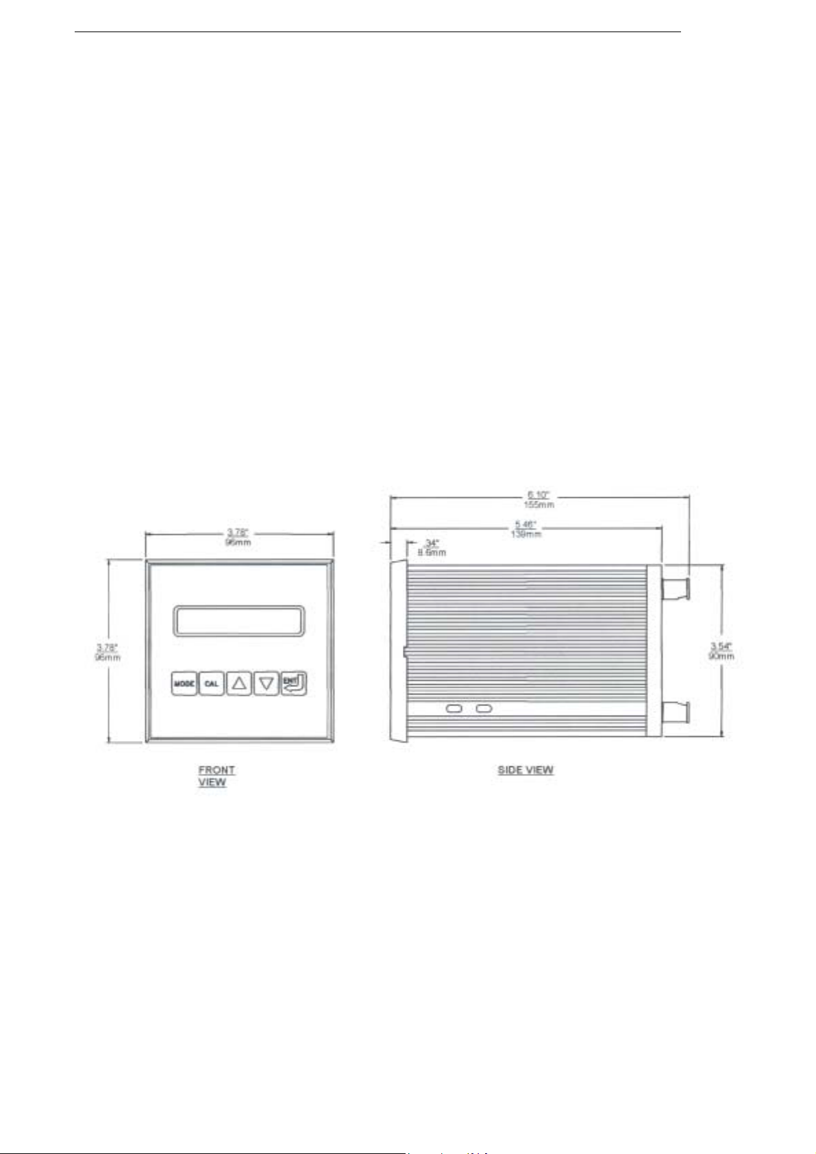
Weight: 850 gr.
Dimensions: 96 x 96 x 155 mm. (DIN 43700)
-8-
B&C Electronics IC 7685 - Rev. B
2.3 PHYSICAL SPECIFICATIONS
The controller enclosure is designed for surface or panel mounting.
It consists of an anodized aluminium case built according to the standard DIN 43700, with an
aluminium panel coated with scratch-proof and non-corrosive polycarbonate membrane.
A transparent waterproof front door SZ 7601 can be added to the housing, in order to protect the
unit from excessive moisture or corrosive fumes.
Signal and power cable connections are made by using two special extractable terminal blocks
placed in the back of the instrument.
This makes wiring, installation and general maintenance of the probes and other devices easier.
The package is supplied complete with fixing clamps for panel-mounting.
-9-
B&C Electronics IC 7685 - Rev. B
3 SOFTWARE DESCRIPTION
3.1 KEYBOARD
KEY FUNCTION
- it allows the operator to go to the next Display
- it allows to go back to the main Display. The eventual new
parameter values will not be memorized
ù
§
ò
ç
- it allows the access of calibration sequences
- it allows to increase the displayed parameters
- it allows to choose between different functions
- it allows to decrease the displayed parameters
- it allows to choose between different functions
- it allows to enter the selected data and to return to the main
Display D0
£
-10-
B&C Electronics IC 7685 - Rev. B
3.2 READOUT SEQUENCES
Applying the power to the instrument the display will show the Ion selected for approximately 3
seconds, then will show the main display (D0).
X+ positive monovalent ion
(X++) positive bivalent ion
(X-) negative monovalent ion
(X--) negative bivalent ion
Press ù to visualize the following Display:
D0
ISE meter X+
xxx.xPPM ìAL ì BH
Concentration Value, set-point
status/functions
D1
D2
D3
D4
D5
D6
D7
PPM x point cal
xxx.x mV X++
TEMP.: xx.x°CM
Termos.: OFF
SA xxx.xPPM*à LO
SB xxx.xPPM*à HI
AL x.x/xxx.xpp
ISE calibration
mV supplied by ISE
Temperature value
Thermocompensation parameters
Set-point A parameters
Set-point B parameters
Alarm parameters
D8
D8bis
01 xx.xmA/xxx pp
02 xx.xmA/xxx pp
-11-
Analog output Nr. 1/input values
Analog output Nr. 2/input values

B&C Electronics IC 7685 - Rev. B
D9
Configuration
Configuration display
D10
IC7685 R2.1x
Instrument P/N and software release
----------------------------------
(D0) Concentration value, set-point
status/functions
xxx.xPPM Concentration value
(>>>>) over range
(flashing values) alarm condition
(M flashing) manual operating mode
ì A relay A deactivated
(è A) relay A delayed
(à A) relay A activated
ì B relay B deactivated
(è B) relay B delayed
(à B) relay B activated
L minimum function (LO)
H maximum function (HI)
xxx.xPPMì ALM à BH
§ to activate the procedure of the manual/automatic mode selection
-12-

B&C Electronics IC 7685 - Rev. B
ù to go to
----------------------------------
(D1) ISE calibration
x Number of memorized calibration points
§ to activate the calibration sequence
PPM x point cal
ù to go to
----------------------------------
(D2) mV supplied by ISE
xxx.x mV mV given by the electrode
X++ ion valence
xxx.x mV X++
ù to go to
----------------------------------
(D3) Temperature value
xx.x Temperature value
M manual value
§ to activate the Temperature calibration or the procedure of the manual
TEMP.: xx.x°CM
Temperature value selection
ù to go to
----------------------------------
(D4) Thermocompensation parameters
OFF thermocompensation deactivated
(ON) thermocompensation activated
TERMOC.: OFF
-13-

B&C Electronics IC 7685 - Rev. B
§ to activate the thermocompensation parameters calibration
ù to go to
----------------------------------
(D5) Set-point A parameters
SA set-point A parameters
xxx.xPPM set-point value
à set-point A status (relay activated)
LO selected function (minimum)
* alarm function on set-point A is activated
§ to activate the set-point value, hysteresis and delay time programming sequences
SA xxx.xPPM*à LO
ù to go to
----------------------------------
(D6) Set-point B parameters
SB set-point B parameters
xxx.xPPM set-point value
à set-point B status (relay activated)
HI selected function (maximum)
* alarm function on set-point B is activated
§ to activate the set-point value, hysteresis and delay time programming sequences
SB xxx.xPPM*à HI
ù to go to
----------------------------------
(D7) Alarm parameters
AL Concentration values alarm (PPM)
x.x low alarm value
xxx.x actual high alarm value
AL x.x/xxx.xpp
§ to activate the alarm values programming sequences
-14-

B&C Electronics IC 7685 - Rev. B
ù to go to
----------------------------------
(D8) analog output Nr.1/input values
01 selected analog output Nr.1
xx.xmA analog output value (mA)
xxx pp input measuring value (PPM)
(xxx°C) Temperature value (option 091.3711)
01 xx.xmA/xxx pp
ù to go to
----------------------------------
(D8BIS) analog output Nr.2/input values
02 selected analog output N°2 (option 091.3711)
xx.xmA analog output value (mA)
xxx pp input measuring value (PPM)
(xxx°C) Temperature value
02 xx.xmA/xxx pp
ù to go to
----------------------------------
(D9) Configuration display
§ to activate the programming sequences of keyboard lock/unlock, display
Configuration
contrast, visualization and modification of the instrument configuration
parameters
ù to go to
----------------------------------
(D10) Instrument P/N and software release
IC7685 R2.1x
ù to go back to the main display (D0)
-15-

B&C Electronics IC 7685 - Rev. B
3.3 CALIBRATION SEQUENCES
The following procedures will be active whenever the instrument is not in the keyboard lock
condition.
To unlock the keyboard follow the procedures mentioned in the "Configuration" chapter.
The following procedures allow the sensor calibration, the set-point and alarm parameters
programming.
The sequence (1, 2, ....) helps the operator to following the regular calibration sequence.
IMPORTANT NOTE: during the calibration procedure the microprocessor turn the unit to the
main display if no keys have been pressed within 5 minutes (30 minutes for ISE calibration
sequences).
3.3.1 Manual/automatic mode
Normally the instrument works in automatic mode.
Follow this procedure to change operating mode Automatic/Manual.
1.
(D0)
2.
AUTO automatic mode
(MANUAL) manual mode
3.ò ç to select the operating mode
ù to go to
xxx.xPPM ìAL ì BH
§ to access the operating mode selection
CAL MODE: AUTO
ù to go back to (DO)
-16-

B&C Electronics IC 7685 - Rev. B
4.£ to confirm the selected operating mode and to go back to (DO)
MESSAGE FUNCTION
the selection has been memorized
The unit go back to (D0)
“ UPDATE “
3.3.2 Ion Selective Electrode Calibration
This calibration is necessary when installing the new ISE electrode.
It is necessary to provide from 2 to 5 standard solutions.
The Concentration of the next solution must be no more of 100 times (2 decades).
The electrode's output of the next solution must be
∆ mV > 10 mV.
1.ù to go to
(D1)
Calibration point insertion:
2.
Nr. x number of the calibration points (1/5)
(see "Calibration procedure deletion")
§ to access the calibration sequences
PPM x point cal
CAL POINT Nr. x
ù to delete the calibration procedure
(see "Calibration procedure ending")
£ to end the calibration procedure
-17-

B&C Electronics IC 7685 - Rev. B
3.§ to insert the Nr.x point
Immerse the electrode into the standard solution
xxx.xmV signal supplied by the electrode
ù to exit from the procedure
4.£ to confirm and to go to the decade selection
100.0 decade
CAL Px:±xxx.xmV
Px DECADE: 100.0
ù to exit from the procedure
5.ò ç to select the decade
6.£ to access the calibration point value insertion
Px calibration point number
xxx.x actual value of the calibration point Px
ù to exit from the procedure
Px Value: xxx.x
7.ò ç to insert the new calibration value
-18-

B&C Electronics IC 7685 - Rev. B
8.£ - to confirm the calibration value
- to go to the next point Px (from 2 to 5)
- if Px=5 the unit will check the validity of the calibration
Calibration procedure deletion
1.ù press this key during the visualization of the calibration point number
(CAL POINT Nr. x)
ABORT POINT CAL?
ù to abort the calibration procedure and to go back to the visualization
of the calibration point number
2.£ to delete the calibration and to go back to (D1)
Calibration procedure ending
The calibration may be ended from the following display:
1.£ to start the ending of the procedure
CAL POINT Nr. x
END POINT CAL?
ù to annul the ending procedure and to go back to the visualization of
the calibration points number
2.£ to end the calibration and to go to the inserted point check
-19-

B&C Electronics IC 7685 - Rev. B
Calibration validity check
During the validity check, the instrument will show the following message:
1. If the inserted points are proper, the following message will be displayed:
£ to stop the message and to go to the display D1
2. If the inserted points have any error, the following message will be displayed:
n (2/5) wrong point number
CHECK CAL POINT
VALUE UPDATED
POINT n ERROR
£ to visualize the type of error
Messages and type of errors during the calibration:
The response curve is inverse (check the ion type selection).
Slope is < 50% of the nominal value.
(Nominal value for monovalent ions (X+ X-): 56 mV/decade)
(Nominal value for bivalent ions (X++ X--): 28 mV/decade)
Check if X++ (X--) has been selected instead of X+ (X-)
Slope is > 200% of the nominal value
Check if X+ (X-) has been selected instead of X++ (X--)
WRONG ION
SLOPE TOO LOW
SLOPE TOO HIGH
-20-

B&C Electronics IC 7685 - Rev. B
The calibration point is 2 decades far from the previous one.
Choose a second standard solution with lower concentration. (<100 times)
The calibration point is < 10 mV far from the previous one.
Choose a second standard solution with higher concentration. (>10 times)
£ to go back to the wrong point calibration
POINT TOO FAR
POINT TOO NEAR
3.3.3 Electrodes drift adjustment
This is the regular calibration during the electrode's life.
Be sure the 2/5 solutions calibration has been done at least one time before start this kind of
calibration.
Prepare a standard solution with a Concentration value close to the process value.
Operate in the same way as described in the chapter regarding the calibration of one point.
End the procedure just after the first point calibration.
The procedure start from the display:
CAL Px: ± xxx.xmV
Messages during the zero calibration:
If the zero calibration is correct, the instrument will show the following message:
After 2 seconds the message will disappear and the unit will go back to (D1).
ò + ç + £ pressing the 3 keys the unit will turn to the factory
calibration (drift adjustment 0.0 mV)
ZERO PNT UPDATED
-21-

B&C Electronics IC 7685 - Rev. B
If the deviation value is > 100 mV, the following message will appear:
After 5 minutes the message will disappear and the unit will go back to (D1). The new Zero
value is not memorized.
It is necessary to calibrate the unit with 2 standard solutions at least.
£ to acknowledge the error message.
The message 'NO UPDATE' will appear for 2 seconds, then the unit goes
back to (D1).
Z> 100mV
3.3.4 Temperature calibration
1.ù to go to
(D3)
2.§ to access the calibration procedure
xx.x measured Temperature value
>>>>>> Temperature value over range
3.ò ç to modify the actual value
TEMP.: xx.x °C
CAL T xx.x °C
ù to exit from the procedure and to go back to (D3)
ò + ç + £ press the 3 keys to turn to factory calibration
4.£ to confirm and to go to the manual Temperature insertion
CAL T.M: xx.x °C
-22-

B&C Electronics IC 7685 - Rev. B
xx.x manual Temperature value
ù to exit from the procedure and to go back to (D3)
5.ò ç to modify the actual value
6.£ to confirm and to go back to (D3)
MESSAGE FUNCTION
The calibration is accepted
ERROR MESSAGES
Zero > 2.0°C The above message will last for
“ UPDATE “
Z > 2.0°C
5 minutes.
£ to acknowledge the error messages
the calibration is not accepted.
The unit go back to (D3)
“ NO UPDATE “
-23-

B&C Electronics IC 7685 - Rev. B
3.3.5 Thermocompensation parameters
The Automatic Temperature Compensation may be effected only when the isothermal value is
known.
Select OFF in the following step 3 if the value is unknown.
1.ù to go to
(D4)
2.§ to access the calibration sequences
OFF thermocompensation deactivated
(ON) (thermocompensation activated)
Termocomp:OFF
CAL TC: OFF
ù to exit from the procedure and to go back to (D4)
3.ò ç to select ON or OFF
4.£ to confirm and to go to the thermocompensation coefficient selection
x.xxx Thermocompensation coefficient value
ù to exit from the procedure and to go back to (D4)
5.ò ç to modify the value
CAL TC:x.xxx%/°C
-24-

B&C Electronics IC 7685 - Rev. B
6.£ to confirm and to go to the isothermal point insertion
xxx.x electrode's isothermal value
ù to exit from the procedure and to go back to (D4)
7.ò ç to modify the inserted value
CAL Ipp: xxx.xmV
8.£ to confirm and to go back to (D4)
3.3.6 Alarm calibration
The following operations are possible:
- to select the min/max alarm value
- to select the delay time value
1.ù to go to
(D7)
2.§ to access the calibration sequences
AL x.x/xxx.xpp
AL L low alarm calibration
x.xpp actual low alarm value
ù to exit from the procedure and to go to (D7)
CAL AL L: x.xpp
-25-

B&C Electronics IC 7685 - Rev. B
3.ò ç to insert the alarm value
4.£ to confirm and to go to the high alarm insertion
AL H high alarm calibration
xxx.xpp high alarm value
ù to exit from the procedure and to go to (D7)
CAL AL H:xxx.xpp
5.ò ç to insert the alarm value
6.£ to confirm and to go to the delay time selection
AL D delay alarm calibration
x.xs delay time value
ù to exit from the procedure and to go to (D7)
7.
8.
ò ç to insert the delay value
£ to confirm and to go back to (D7)
CAL AL D: x.xs
The new data have been memorized
“ UPDATE “
-26-

B&C Electronics IC 7685 - Rev. B
3.4 CONFIGURATION
The following operations are possible:
- keyboard locked/unlocked selection
- display contrast selection
- access number insertion
1.ù to go to
(D9)
2.§ to access the configuration sequences
Configuration
3.4.1 Keyboard locked/unlocked
_
UNLOCKED (LOCKED) Keyboard unlocked (locked)
ù to go back to (D9)
3.
4.
ò ç to select one of the two options (locked/unlocked)
£ to confirm and to go to the next step
KB UNLOCKED
-27-

B&C Electronics IC 7685 - Rev. B
3.4.2 LCD display contrast
x contrast level
ù to go back to (D9)
1.ò ç to select the contrast from 0 to 7
2.£ to confirm and to go to the access number insertion
LCD contrast: x
3.4.3 Set-point A/B calibration
For each set-point it is possible:
- to insert the set-point
- to insert the hysteresis
- to insert the delay time
1.ù to go to
(D5)
(D6)
The following procedure are suitable for both set-point A and B.
SA xxx.xPPM LO
SA xxx.xPPM HI
-28-

B&C Electronics IC 7685 - Rev. B
Set-point value
2.§ to access the calibration sequences
SA set-point A calibration
xxx.xpp set-point value
ù to exit from the procedure and to go back to (D5)/(D6)
CAL SA S:xxx.xpp
3.ò ç to insert the set-point value
4.£ to confirm and to go to the next step
x.xpp actual hysteresis value
ù to exit from the procedure and to go to (D5)/(D6)
5.
6.£ to confirm and to go to the delay time insertion
ò ç to insert the hysteresis value
CAL SA I: x.xpp
x.xs actual delay time value
CAL SA D: x.xs
ù to exit from the procedure and to go to (D5)/(D6)
-29-

B&C Electronics IC 7685 - Rev. B
7.ò ç to insert the delay time value
8.£ to confirm and to go back to (D5)/(D6)
The calibration is accepted
“ UPDATE “
3.4.4 Access number
0 access number request
Access Nr.: 0
ù to go back to (D9)
1.ò ç to insert the access number (when keeping the key pressed the number
will scroll with 3 speed level)
2.£ to confirm and to proceed with the configuration
IMPORTANT NOTE: any number different from the right access code, will allow the
visualization of the parameters and not the modification.
The following message will appear:
MESSAGE FUNCTION
Configuration changes are inhibited
‘Cal Inhibition’
-30-

B&C Electronics IC 7685 - Rev. B
3.4.5 Ion valence
X+(X--)(X-)(X+) type of selected ion
ù to go back to (D9)
1.ò ç to select the type of ion
2.£ to confirm and to go to the next step
Before modifying the type of ion, the unit need the confirmation.
The type of ion modification cancels the calibration points previously memorized and turn the unit
to the factory calibration.
TYPE OF ION:X+
Reset PPM cal?
ù to go back to (D9)
3.£ to confirm the type of ion and to reset the calibration point
-31-

B&C Electronics IC 7685 - Rev. B
3.4.6 Measuring unit
PPM (g/l mbar mg/l mmHg): selected measuring unit
Measure U.: PPM
(g/l mbar mg/l mmHg)
ù to go back to (D9)
1.ò ç to select the measuring unit
2.
3.4.7 Set-point scale, alarm and analog output
(10.00 - 1000)
100.0 (10.00) (1000) selected scale
ù to go back to (D9)
1.ò ç to select the scale
2.
£ to confirm and to go to the next step
Scale: 100.0 PPM
£ to confirm and to go to the next step
Note:
set-point, alarm and analog output values will be shown in the scale as selected.
-32-

B&C Electronics IC 7685 - Rev. B
3.4.8 Software filter
Large s RT response time for large fluctuations
x.xs software filter value (sec.)
ù to go back to (D9)
1.ò ç to select the time
2.£ to confirm and to go to the next step
Large s RT x.xs
Small s RT response time for small fluctuations
xx.xs response time value (in sec.)
ù to go back to (D9)
3.ò ç to select the time
4.
£ to confirm and to go to the next step
Small s RT: xx.xs
-33-

B&C Electronics IC 7685 - Rev. B
3.4.9 Scale of the analog output n°1
PPM (°C) input/analog output Nr.1
ù to go back to (D9)
1.ò ç to select values in PPM (°C)
2.£ to confirm and to go to the next step
CAL OUT1: PPM
3.4.10 Analog output n°1 range
0/20mA (4/20mA) range selected
ù to go back to (D9)
1.
2.
ò ç to select the output range
£ to confirm and to go to the next step
CAL OUT1: 0/20mA
P1 begin of the output range
x.xPPM measuring value related to 0/4 mA
ù to go back to (D9)
CAL P1: x.xPPM
-34-

B&C Electronics IC 7685 - Rev. B
3.ò ç to choose the value x.x in PPM
4.£ to confirm and to go to the next step
P2 end of the output range
xxx.xPPM measuring value related to 20 mA
ù to go back to (D9)
CAL P2: xxx.xPPM
5.ò ç to choose the value xxx.x in PPM
6.£ to confirm and to go to the next step
IMPORTANT NOTE: if the value related to P1 is higher than the value related to P2, the
analog output will be the "reverse", otherwise will be the "direct" type.
-35-

B&C Electronics IC 7685 - Rev. B
3.4.11 Scale of the analog output n°2
_
PPM (°C) input/analog output n°2
ù to go back to (D9)
1.ò ç to choose the values in PPM
2.£ to confirm and to go to the next step
CAL OUT: PPM
3.4.12 Analog output n°2 range
0/20mA (4/20mA) range selected
CAL OUT2: 0/20mA
£ to go back to (D9)
1.
2.£ to confirm and to go to the next step
P1 begin of the output range
x.xPPM measuring value related to 0/4 mA
ò ç to select the output range
CAL P1: x.xPPM
£ to go back to (D9)
-36-

B&C Electronics IC 7685 - Rev. B
3.ò ç to choose the value x.x in PPM
4.£ to confirm and to go to the next step
P2 end of the output range
xxx.xPPM measuring value related to 20 mA
£ to go back to (D9)
CAL P2: xxx.xPPM
5.ò ç to choose the value xxx.x in PPM
6.£ to confirm and to go to the next step
IMPORTANT NOTE: if the value related to P1 is higher than the value related to P2, the
analog output will be the "reverse", otherwise will be the "direct" type.
-37-

B&C Electronics IC 7685 - Rev. B
3.4.13 Set-point A function
F function
LO (HI) minimum (maximum)
ù to go back to (D9)
1.ò ç to select the function LO or HI
2.£ to confirm and to go to the next step
SET A F.: LO
3.4.14 Set-point B function
F function
LO (HI) minimum (maximum)
1.
2.£ to confirm and to go to the next step
ò ç to select the function LO or HI
SET B F.: LO
ù to go back to (D9)
-38-

B&C Electronics IC 7685 - Rev. B
3.4.15 Set-point A alarm
ON (OFF) alarm inserted (not inserted)
ù to go back to (D9)
1.ò ç to select ON or OFF
AL SET A: ON
2.
- by selecting OFF the alarm function is not activated.
The unit goes to the next parameter calibration.
- by selecting ON the alarm function is activated.
(when the relay B will be active longer than the time selected in the
xx m activation time
3.
4.
£ to confirm and to go to the next step
following procedure).
TIME SET A: xx m
ù to go back to (D9)
ò ç to choose the time value
£ to confirm and to go to the next step
-39-

B&C Electronics IC 7685 - Rev. B
3.4.16 Set-point B alarm
ON (OFF) alarm inserted (not inserted)
ù to go back to (D9)
1.ò ç to select ON or OFF
2.£ to confirm and to go to the next step
AL SET B: ON
- by selecting OFF the alarm function is not activated.
The unit goes to the next parameter calibration.
- by selecting ON the alarm function is activated.
(when the relay B will be active longer than the time selected in the
following procedure).
xx m activation time
3.
4.£ to confirm and to go to the next step
ò ç to choose the time value
TIME SET B: xx m
ù to go back to (D9)
-40-

B&C Electronics IC 7685 - Rev. B
3.4.17 Alarm relay contact
ACT (DEA) relay activated (deactivated) when the alarm is active
ù to go back to (D9)
1.ò ç to select ACT or DEA
2.£ to confirm and to go to the next step
AL RELAT: ACT
3.4.18 New access number
NO (YES) access number changing not required (required)
1.
2.
- by selecting NO the unit will go to the Configuration display
- by selecting YES the unit will go to the following display:
xxx actual access number
ò ç to select NO or YES
£ to confirm and to go to the next step
Change A Nr.: NO
ù to go back to (D9)
New Nr.: xxx
ù to go back to (D9)
-41-

B&C Electronics IC 7685 - Rev. B
3.ò ç to insert the new access number
4.£ to confirm and to go to the next step
The instrument ask the operator to insert again the new access number.
xxx actual access number
ù to go back to (D9)
Confirm Nr.:xxx
5.ò ç to insert the new access number
6.£ to confirm and to go back to the beginning of the Configuration
The double insertion of the new access number assures the memorization
of the right code.
As soon as the new number is memorized the message "UPDATE" will
appear.
Should the operator insert two different numbers, the instrument will not
modify the access number and the message "NO UPDATE" will be
shown.
£ press several time the key to verify the selected parameters before
leaving the Configuration routine.
ù press to exit from the Configuration menu.
-42-

B&C Electronics IC 7685 - Rev. B
4 INSTALLATION
4.1 CONTROLLER INSTALLATION
The controller may be installed close to the points being monitored, or it may be located some
distance away in a control area.
The enclosure is designed for panel-mounting.
It should be mounted on a rigid surface, in a position protected from the possibility of damage or
excessive moisture of corrosive fumes.
4.2 SENSOR INSTALLATION
See the instruction manual of the sensor.
4.3 ELECTRICAL INSTALLATION
Connections within the controller are made on detachable terminal strips
located on the rear side. (fig. 2)
Power and output-recorder connections are made at the 13 pin terminal strip, while input signal
connections are made at the 12 pin terminal strip.
Connecting the power
- terminal 4 connect to the ground
- terminals 1-2 connect to the ac power (if power is 110 V)
- terminals 1-3 connect to the ac power (if power is 220 V)
(If 091.404 option is installed, connect 24 Vac to 1-3 terminals)
WARNINGS
- power the device by means of an isolation transformer
- avoid mains-voltage from an auto-transformer
- avoid mains voltage from a branch point with heavy inductive loads
- separate power supply wires from signal ones
- control the mains voltage value
- an internal device protects the unit against power overloads.
Disconnect the power and wait few minutes before powering again.
-43-

B&C Electronics IC 7685 - Rev. B
Connecting the Ion Selective Electrode (ISE)
- terminal 22 connect to the Ion Selective Electrode
- terminal 21 connect to the Reference electrode
(Normally in the combination ISE the Reference electrode is connected to the shield of the coax
cable)
Avoid interruption on the cable if a high insulation terminal block is not available.
Keep the cable away from power wires on the overall length.
Connecting the RTD
The Temperature readout and the automatic Temperature compensation is provided by connecting
the Pt100.
If the Temperature sensor is not connected or damaged, the unit will operate in manual
Temperature compensation automatically.
3-wire connection
- terminal 23 connect to the Pt100
- terminals 24 - 25 connect to the Pt100 common
2-wire connection
- terminals 23 - 24 connect to the Pt100
- terminals 24 - 25 install a jumper between terminals
Connecting a recorder
Connect to terminals 14-16 for the 1st channel output
Connect to terminals 15-16 for the 2nd channel output (091.3711 option)
- terminal 14 connect to the terminal (+) of the recorder N°1
- terminal 15 connect to the terminal (+) of the recorder N°2
- terminal 16 connect to the terminal (-) of the two recorder
Series connection is required for driving more loads having a total input Resistance lower than
600 ohm for each channel.
Connecting alarms, pumps, valves
The output connections referred to set-point SA and set-point SB are made at terminal strip and
they consist of two independent SPDT relays corresponding to Regulator A and Regulator B.
The output connection referred to alarm consists of SPDT relay corresponding to Alarm C/D.
-44-

B&C Electronics IC 7685 - Rev. B
RELAY "A" SET-POINT "SA"
terminal 6 marked C common contact
terminal 5 marked NO normal open contact
terminal 7 marked NC normal closed contact
RELAY "B" SET-POINT "SB"
terminal 9 marked C common contact
terminal 8 marked NO normal open contact
terminal 10 marked NC normal closed contact
RELAY "C/D" ALARM
terminal 12 marked C common contact
terminal 11 marked NO normal open contact
terminal 13 marked NC normal closed contact
Arc suppressor
Install a suitable snubber between relay terminals if the relay activation causes interferences on
the display. (B&C Electronics snubber SX101)
-45-

B&C Electronics IC 7685 - Rev. B
5 OPERATING THE SYSTEM
Checking
Before connecting the system to the power supply:
- check that all cables are properly fastened to prevent strain on the connections
- check that all terminal-strip connections are mechanically and electrically sound
- check that power voltage is correct
Pre-operation check
The system's controls and indicators are all located on the front panel
(see fig.1).
The meter has a LCD display 1 indicating that the unit is on.
The cards of the controllers are adjusted at the factory.
If sensors have been connected correctly, as described in the above sections, the system should
function correctly needing only the start up and the parameters calibrations as described in the
following section.
Quick start guide
The unit may be installed for the following purposes:
- measuring
- measuring and regulation
- measuring, regulation and recording
The instrument is shipped with factory calibration and configuration suitable for the most popular
applications.
For this reason the operation may require just the following steps:
measuring
1. Connect the electrode to the meter.
2. Switching-on the meter will assume the factory calibration.
The display will go to (D0) Display.
3. The meter is configured for monovalent ions (ion type X+) and 100.0 PPM scale.
Go to the Configuration menu in order to select other ion types.
From (D0) press 9 times ù to start the Configuration sequence.
4. Carry out the first calibration (from 2 to 5 points).
-46-

B&C Electronics IC 7685 - Rev. B
measuring and regulation
Add the following to the preceding operations:
1. Press § ò £ to go to the manual operation.If the automatic mode is selected, go
to the step 2
2. A and B relay are configured as LOW (Minimum).
Select HIGH (Maximum) if necessary.
3. Select the Set-point, the Hysteresis and the Delay of A and B relay. From (D0) press 5
times ù to start the Set-point A selection sequence.
From (D0) press 6 times ù to start the Set-point B selection sequence.
4. The alarm on the activation time of A and B relay is deactivated.
Activate this kind of alarm if necessary.
5. Select alarm values of min/max and delay if necessary.
From (D0) press 7 times ù to start the alarm selection sequence.
measuring, regulation and recording
Add the following to the preceding operations:
1. Analog output is configured as PPM at 0/20 mA corresponding to the input scale.
Select 4/20 mA and a suitable input span if necessary.
2. If option 091.3711 is installed, follow the step 1. for the second output.
This option allows to select the analog output as °C scale.
Manual operation
When the instrument is programmed for the manual operation (see Calibration sequences) the
flashing "M" will appear on the display.
Analog outputs and alarm relay will remain activated.
ò while pressing the key, A relay will be activated.
ç while pressing the key, B relay will be activated.
Temperature compensation
Do not activate the Temperature compensation if the isothermal value and the
thermocompensation Coefficient of the electrode are not known.
Following the Nernst's law the thermocompensation Coefficient is:
- 0.198 %/°C (monovalent ions)
- 0.099 %/°C (bivalent ions)
-47-

B&C Electronics IC 7685 - Rev. B
The above values should be confirmed by electrode's manufacturer.
The isopotential point change depending on the type of the measured ion.
Check the value declared by electrode's manufacturer.
The manual compensation is in alternative to the automatic compensation.
Do not install The RTD and select the Temperature value and the Temperature coefficient value
(see Pt100 zero calibration).
-48-

B&C Electronics IC 7685 - Rev. B
6 CALIBRATION
Concentration measuring
This calibration is necessary when:
- the electrode is replaced or the ion type is changed (X--, X-, X+, X++);
- periodically, in order to maintain a good accuracy.
Prepare from 2 up to 5 standard solutions.
We suggest standard solutions corresponding to the decades (0.10/1.00/10.00/100.0/1000).
From (D0) press ù to start the calibration procedures. (see 3.1)
During the calibration the unit measures the mV signal from the electrode, while the operator
insert the corresponding concentration value in PPM.
The instrument effects the validity check of the calibration points.
If a calibration point is not valid, an error message will appear together with the number of the
point.
The operator may repeat the calibration of this point.
The unit consider not valid the following calibration points:
- if between 2 points there are less than 10 mV
- if between 2 points there are more than 2 decades
- if slope is less than 50% or more than 200% of the regular slope
- if the slope is negative instead of positive (or vice versa).
The point corresponding to zero concentration is deleted.
During the calibration, control relays and alarm relay are deactivated.
Electrode's drift adjustment
This is the regular calibration to be effected during the electrode's life, by using a standard
solution having a concentration value close to the process value.
By inserting just one calibration point, the unit will effect the electrode's drift adjustment.
(see 3.1.3)
Temperature calibration
From (D0) press ù to start the Temperature calibration sequence.
Immerse the Temperature sensor in a liquid at known Temperature and check the correspondent
value on the display.
Follow the first 4 steps of the procedure in the Chapter 3.1.4. to adjust the Temperature value
-49-

B&C Electronics IC 7685 - Rev. B
7 PREVENTIVE MAINTENANCE
Controller
Quality components are used to give the controller a high reliability.
The frequency of such maintenance depends on the nature of each particular application.
As in any electronic equipment, the mechanical components, such as switches, relays and
connectors, are the most subject to damage.
Sensor
The state of the electrode's surface is critical for the normal operation of the system.
For the ISE maintenance see the manufacturer instruction manual.
Protect the sensor from humidity, excessive moisture or corrosive fumes.
-50-

B&C Electronics IC 7685 - Rev. B
-51-

B&C Electronics IC 7685 - Rev. B
IC 7685
REAR PANEL CONNECTIONS
1.2. 110 V. Power supply
1. 3. 220 V. Power supply
4. Ground (power)
5. 6. A Relay N.O. contacts
6. 7. A Relay N.C. contacts
8. 9. B Relay N.O. contacts
9.10. B Relay N.C. contacts
11.12. C Relay N.O. contacts (alarm)
12.13. C Relay N.C. contacts (alarm)
14. Recorder output 1 (+)
15. Recorder output 2 (+) (option)
16. Recorder output 1 and 2 (-)
21. Reference Electrode input
22. Ion Selective Electrode input
23.24.25. Temperature sensor input
FIG. 2
-52-

B&C Electronics IC 7685 - Rev. B
-53-
 Loading...