

CERT. N. 9115 BCEL
INSTRUCTION MANUAL
UNI EN ISO 9001:2000
CL 7685
RESIDUAL CHLORINE
CHLORINE DIOXIDE - D. OZONE
MICROPROCESSOR CONTROLLER
* potentiostatic *
Range: 0/2.000/20.00 PPM
Temperature range: -2/+52 °C
Power supply: 110/220 Vac
Software: R:2.4 x
Option
S/N
REP N°
Cod. 28006765 - Rev. D - 11/06
B&C Electronics Srl - Via per Villanova 3 - 20040 Carnate (Mi) - Italy - P.IVA 00729030965
Tel +39 039 63 1721 - Fax +39 039 607 6099 – bc@bc-electronics.it - www.bc-electronics.it

B&C Electronics CL 7685
Index
1 GENERAL .........................................................................................................................................4
1.1 Functional specifications ..........................................................................................................5
1.2 Physical description..................................................................................................................8
2 SPECIFICATIONS............................................................................................................................9
3 INSTALLATION ............................................................................................................................14
3.1 Physical installation................................................................................................................14
3.2 Electrical installation ..............................................................................................................14
3.3 Operating the system ..............................................................................................................17
4 KEYBOARD ...................................................................................................................................18
5 READOUT SEQUENCES ..............................................................................................................19
6 CALIBRATION SEQUENCES ......................................................................................................23
6.1 Operating mode selection .......................................................................................................23
6.2 Zero and sensitivity calibration ..............................................................................................24
6.3 Temperature calibration..........................................................................................................28
6.4 Set-point A/B setting ..............................................................................................................29
6.5 Alarm setting ..........................................................................................................................33
6.6 Cleaning function ...................................................................................................................34
7 CONFIGURATION.........................................................................................................................37
7.1 Keyboard locked/unlocked .....................................................................................................37
7.2 LCD display contrast ..............................................................................................................37
7.3 Access number........................................................................................................................38
7.4 Type of measuring ..................................................................................................................38
7.5 Input range..............................................................................................................................38
7.6 Autorange ...............................................................................................................................39
7.7 Software filter .........................................................................................................................39
7.8 Cell polarization voltage.........................................................................................................39
7.9 Calibration mode ....................................................................................................................39
7.10 Temperature coefficient..........................................................................................................40
7.11 Input related to analog output n°1 (option 091.3711) ............................................................40
7.12 Analog output n°1 range.........................................................................................................40
7.13 Input related to analog output n°2 (option 091.3711) ............................................................41
7.14 Analog output n°2 range.........................................................................................................41
7.15 Set-point A operating mode....................................................................................................42
7.16 Set-point A function ...............................................................................................................42
7.17 Set-point B operating modE ...................................................................................................42
7.18 Set-point B function................................................................................................................43
7.19 Alarm on Set-point A .............................................................................................................43
7.20 Alarm on Set-point B..............................................................................................................43
7.21 Alarm relay contact function ..................................................................................................44
7.22 Alarm type ..............................................................................................................................44
7.23 alarm flashing frequency ........................................................................................................44
7.24 Cleaning function ...................................................................................................................45
7.25 Cleaning time (relay D on) .....................................................................................................45
Instruction Manual - Rev. D - 11/06
- 2 –

B&C Electronics CL 7685
7.26 Holding time ...........................................................................................................................45
7.27 New access number ................................................................................................................45
8 CALIBRATION...............................................................................................................................47
8.1 Electrical calibration...............................................................................................................47
8.2 Chemical calibration...............................................................................................................47
9 PREVENTIVE MAINTENANCE...................................................................................................48
WARRANTY CERTIFICATE...............................................................................................................52
REPAIRS................................................................................................................................................52
TECHNICAL SUPPORT .......................................................................................................................53
Instruction Manual - Rev. D - 11/06
- 3 –

B&C Electronics CL 7685
1 GENERAL
This series of controllers with built-in microprocessor forms an advanced system of measurement and
regulation of pH - ORP - Conductivity - Dissolved Oxygen - Chlorine in industrial processes.
These instruments are the result of all of B&C Electronics know-how built up over more than 30 years
of experience in the field of industrial electrochemical analysis.
We have continually developed and updated these products keeping in mind the maximum
consideration for quality, reliability, completeness of functions, simplicity of handling, and also the
cost.
The computing capability and the versatility of the microprocessor are accompanied by friendly
software specially designed to make the use of the instrument, the programming of its functions,
routine checks and calibrations easily accessible even for an untrained operator.
The alpha-numeric backlit liquid crystal display helps the operator supplying him with all the
information on functioning and on operating, while the software suggests possible steps for calibration
and set-up.
The display supplies, at the same time as the measurement, an indication of present status of the output
relays and of the output current.
For a higher level of checks, the display gives an indication of the operating conditions of the
electrochemical sensors, the current status of the calibrations, set points and analog output.
The user friendly operation of the instrument saves the operator feats of memory and continual
reference to the instruction manual.
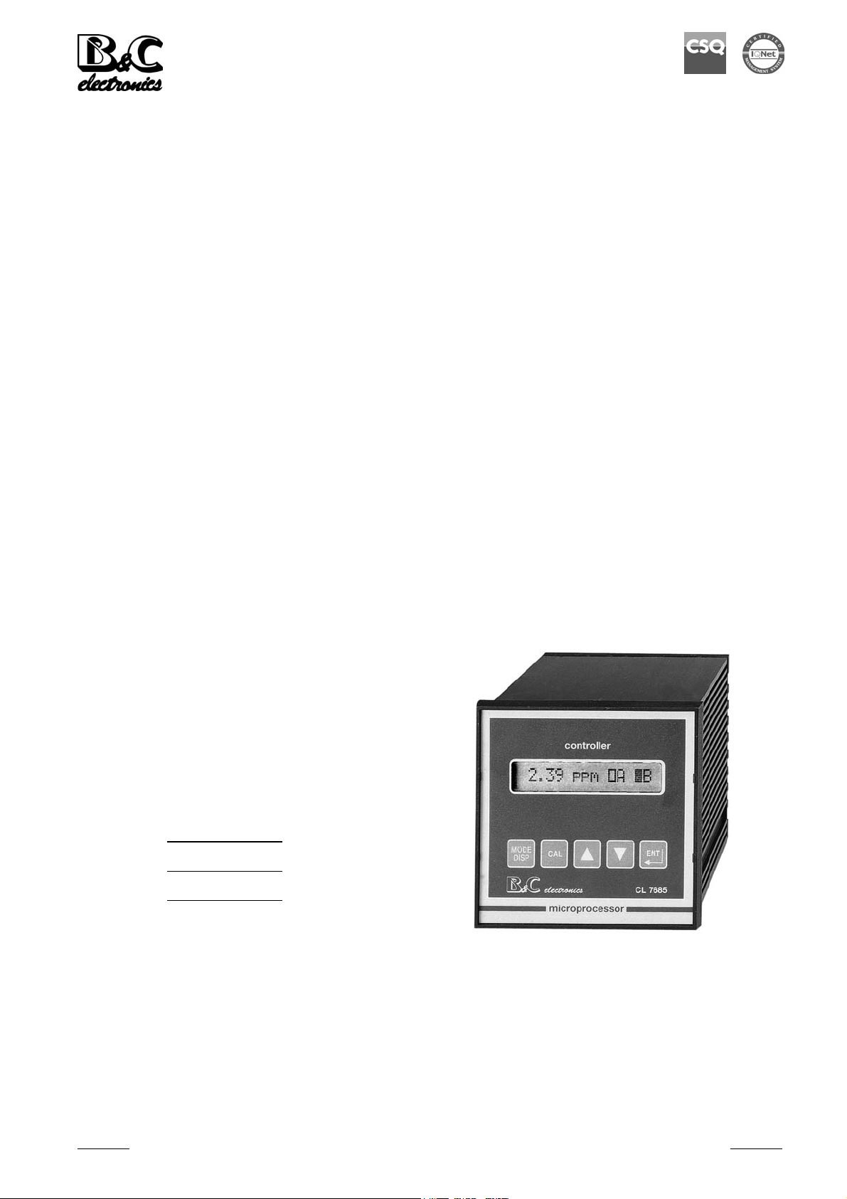
All operations are carried out using the five key pads on the front panel, for the mode selection, the
input of calibration and set point data and the setting-up. (Fig. 1)
There are no knobs or switches to manipulate in order to operate the unit. This makes the instrument
rugged and more corrosion resistant.
A non-volatile EEPROM memory assures measurement parameters are maintained in the event of a
power interruption.
The software is provided with a "watch-dog" check for correct functioning of the programs.
The electrical circuit is protected by a device which comes back into operation automatically following
an overload or a wiring error.
Instruction Manual - Rev. D - 11/06
- 4 –

B&C Electronics CL 7685
1.1 FUNCTIONAL SPECIFICATIONS
Input
The instrument accepts input from potentiostatic sensor for Active Chlorine, Chlorine Dioxide and
D.Ozone measuring.
A second input is provided for 3 wires Pt100 Temperature sensor.
Temperature compensation
The unit is supplied with manual or automatic Temperature compensation and Temperature
information may be displayed on LCD.
The instrument detects the absence or malfunctioning of the Temperature sensor and automatically
switches to manual operation mode.
Measuring ranges
The unit provides an input range which may be selected from 0/1.999 or 0/19.99 PPM.
Auto ranging function may be activated for the measuring range 0/1.999 PPM.
Auto ranging allows the operator to calibrate the unit in the low range, against a high concentration of
standard solution.
Analog output
Either a 0/20 mA or 4/20 mA isolated output may be selected, provided for interface with computer or
data loggers.
A special routine allows selection of the analog output range.
If the instrument is programmed for high range, the output may be set anywhere from 0/20.00 PPM.
If low range is selected, the output may be set anywhere from 0/2.000 PPM.
Control relays
The monitor is equipped with two SPDT control relays.
These output relays may be used in a variety of ways, and the function of each relay is programmable
by operator.
Control relays can be used in one of 3 different output modes: on/off, pulse width modulation and
pulse frequency modulation.
The on/off mode of operation is used for simple control or for alarm purposes. Each control relay may
be programmed for set-point, high/low, hysteresis, delay time for actuation.
The proportional mode of operation is used for more accurate control.
Each control relay may be programmed for set-point, high/low, proportional band, Frequency or Width
modulation.
The full display indicates the current setting and the current status of each relay.
Instruction Manual - Rev. D - 11/06
- 5 –

B&C Electronics CL 7685
Alarm relay
The unit contains a SPST relay designated as an alarm relay.
This relay may be used to warn of various conditions that might indicate operational problems.
The relay will activate on either high or low concentration conditions, or on failure of the control
relays to maintain proper control.
This relay may be programmed for either normal or fail-safe operation.
The software R:2.4x provides the additional function of the selectable continuous/flashing alarm and
the selectable flashing frequency.
Cleaning function
The unit contains a SPST relay designed for the auto clean cycle.
It's possible manually activate the cleaner to test its operation.
The operator can change the frequency of cleaning.
The configuration routine selects:
- auto/manual operation
- the cleaning time
- the holding time.
During cleaning and holding time:
- messages are flashing
- analog output is held constant
- set-points and alarm relays are deactivated.
Operating mode
The instrument is provided with 3 programmable modes of operation.
- Automatic operation (AUTO):
The Automatic mode is the normal operation mode of the unit.
- Measuring operation (MEAS.):
In this mode of operation the display indicates only the concentration, the analog output is active but
the control relays are deactivated.
This would be the mode to use if the relays are not being used for alarm or control functions.
The measuring mode of operation is useful for start up or for manual operation of disinfection plants.
Instruction Manual - Rev. D - 11/06
- 6 –

B&C Electronics CL 7685
- Simulated operation (SIM.):
In this operating mode the users choose the displayed value by means of up/down keys.
The unit maintains the set point, alarm and analog output parameters in order to test the plant.
The display does not indicate the measuring units (PPM) and access to calibration of the parameters is
not allowed.
The message "SIM" is shown on the display, indicating the current operation mode of the instrument.
Calibration mode
The instrument may be programmed for the immediate or postponed calibration.
The immediate calibration mode allows the operator to calibrate the unit immediately against a field
measurement on the same sample that the sensor is measuring.
The postponed calibration mode allows the operator to calibrate the unit against a laboratory
measurement on the same sample that the sensor is measuring.
The calibration may be performed later even if the sample concentration has changed.
Software filter
The unit is provided with a dual programmable software filter, to be inserted when the readout is not
stable.
The filter values can be selected separately for the small or large signal variations.
Configuration
The electronics for the monitor is designed to be as flexible as possible.
A number of programming functions are provided in the Configuration menu, protected by an access
number, which must be entered to allow changes in this setting.
The routine allows the programming of a custom access number.
Front panel lock
The keys on the front panel of the monitor can be used for changing the display, for calibrations and
set-point adjustments.
When the monitor is shipped, all functions are accessible.
However, the adjustment and calibration functions may be locked in order to prevent unauthorized
adjustments to the instrument.
Instruction Manual - Rev. D - 11/06
- 7 –

B&C Electronics CL 7685
Options
091.3711 Dual isolated and programmable output
The operator may select an output for Temperature.
091.404 24 VAC power supply.
091.4143 9/36 VDC power supply.
091.701 RS232 isolated output
The output sends the data (PPM,°C) to the serial port of the computer.
1.2 PHYSICAL DESCRIPTION
The controller enclosure is designed for surface or panel mounting.
It consists of an anodized aluminium case built according to the standard DIN 43700, with an
aluminium panel coated with scratch-proof and non-corrosive polycarbonate membrane.
A transparent waterproof front door SZ 7601 can be added to the housing, in order to protect the unit
from excessive moisture or corrosive fumes.
Signal and power connections are made by using two special extractable terminal blocks placed in
the back of the instrument.
This makes wiring, installation and general maintenance of the probes and other devices easier.
The package is supplied complete with fixing clamps for panel-mounting.
Instruction Manual - Rev. D - 11/06
- 8 –

B&C Electronics CL 7685
2 SPECIFICATIONS
The DEFAULT values are correspondent to the factory calibration values.
Parameters marked by " * " can be modified in the Configuration procedures.
Default
OPERATING MODE
Automatic/Measuring/Simulation Auto
MEASURING TYPE
* Chlorine/Chlorine dioxide/D. Ozone Chlorine
INPUT SCALES
Input range: 2.000/20.00 PPM 20.00
Display resolution at 20 °C: 1/2000
Software filter 90% RT:
* LARGE signal: 0.4/20,0 s 2.0 s
* SMALL signal: 0,4/20,0 s 10,0 s
Current at 20 °C: 250/5000 nA/PPM 2000 nA/PPM
Cell Sensitivity: 12.5/250% 100%
Zero: adjustable 0 µA
* Comp. Temp. Coefficient Cl/ClO2: 0/4.0 % / °C 2.0% / °C
* Comp. Temp. Coefficient O3: 0/4.0 % / °C 2.5% / °C
* Polarization Voltage: adjustable -200 mV
TEMPERATURE
Input: RTD Pt100
Connection: 2/3 wires
Measuring and compensation range: -2/+52 °C
Resolution: 0.1 °C
Zero adjustment: +/- 2°C 0 °C
Manual Temperature compensation: 0/50 °C 20 °C
Instruction Manual - Rev. D - 11/06
- 9 –

B&C Electronics CL 7685
SET A/B
* Selectable actions:
ON-OFF
PFM - Pulse frequency proportional
PWM - Pulse width proportional
* Action: ON-OFF SET B
Value: 0/2.000 - 0/20.00 PPM (as selected scale) 0 PPM
Hysteresis: 0/0.200-0/2.00 PPM (as selected scale) 0.2 PPM
Delay: 0/99.9 s 0.0 s
* Function: HI/LO (Max/min) LO
* Action: PFM SET A
Value: 0/20.00 PPM (as selected scale) 0 PPM
Proportional band: 0/0.200 - 0/2.00 PPM 0.2 PPM
(as selected scale )
Pulse max. Frequency: 0/120 pulse/minute 100 p/m
Pulse width: 0.1 s
* Function: HI/LO (Max/min) LO
* Action: PWM
Value: 0/0.200 - 0/20.00 PPM (as selected scale) 0 PPM
Proportional band: 0/0.200 - 0/2.00 PPM 0.2 PPM
(as selected scale)
Pulse width: 0/99.9 s 20.0 s
Min. pulse width: 0.3"
* Function: HI/LO (Max/min) LO
Relay Contacts: SPDT 220 V 5 A Resistive load
ALARM (RELAY C)
High value: 0/2.000 - 0/20.00 PPM (as selected scale) 20.00 PPM
Low value: 0/2.000 - 0/20.00 PPM (as selected scale) 0.00 PPM
Delay: 0/99.9 s 0.0 s
* Alarm on max. SA: ON/OFF OFF
* Max. time SA: 0/60 minutes 60 min
* Alarm on max. SB: ON/OFF OFF
* Max. time SB: 0/60 minutes 60 min
* Contact type: ACT/DEA ACT
* Alarm type: CONT./FLASH CONT
* Flashing frequency: LO (approx. 0.3 Hz duty cycle) ME
ME (approx. 0.6 Hz duty cycle)
HI (approx. 1.2 Hz duty cycle)
Relay Contact: SPST 220 V 5 A Resistive load
Instruction Manual - Rev. D - 11/06
- 10 –

B&C Electronics CL 7685
CLEANING FUNCTION (RELAY D)
* Action: Disable/Manual Clean/Auto+Manual Clean Disable
Auto Clean:
Repetition time: 0.1/24.0 h 24.0 h
* Cleaning time: 0.5/60.0 s 15.0 s
* Hold time: 0.1/20.0 minutes 3.0 min.
Relay contacts: SPST
ANALOG OUTPUT Nr. 1
* Current range: 0-20/4-20 mA 0/20 mA
* Point 1 corresponding to 0 mA or 4 mA
RANGE 20.00 PPM: 0.00/20.00 0.00 PPM
RANGE 2.000 PPM: 0.000/2.000 0.000 PPM
TEMPERATURE: 0.0°C/50.0°C (Option 091.3711) 0.0 °C
* Point 2 corresponding to 20 mA
RANGE 20.00 PPM: 0.00/20.00 20.0 PPM
RANGE 2.000 PPM: 0.000/2.000 2.000 PPM
TEMPERATURE: 0.0°C/50.0°C (Option 091.3711) 50.0 °C
Response time: 10 s for 98 %
Isolation: 250 Vca
Rmax: 600 Ω
ANALOG OUTPUT N°2 (Only for Option 091.3711)
* Current range: 0-20/4-20 mA 0/20 mA
* Point 1 corresponding to 0 mA or 4 mA
RANGE 20.00 PPM: 0.00/20.00 0.00 PPM
RANGE 2.000 PPM: 0.000/2.000 0.000 PPM
TEMPERATURE: 0.0 °C/50.0 °C 0.0 °C
* Point 2 corresponding to 20 mA
RANGE 20.00 PPM: 0.00/20.00 20.00 PPM
RANGE 2.000 PPM: 0.000/2.000 2.000 PPM
TEMPERATURE: 0.0 °C/50.0 °C 50.0 °C
Response time: 10 s for 98 %
Isolation: 250 Vca
Rmax: 600 Ω
Instruction Manual - Rev. D - 11/06
- 11 –

B&C Electronics CL 7685
SERIAL COMMUNICATION (Option 091.701)
Baud Rate: 4800 bit/s
Nr. of bit: 8 bit
Nr. of stop bit: 1 bit
Parity: None
Isolated from measure circuits
Example of data sent: ± 20.00 PPM ± 50.0 °C
Data sent every: 0.4 s
PARAMETERS ON CONFIG. BLOCK (See for *)
Free calibration (access code not required):
Keyboard Lock/Unlock Unlock
LCD contrast (0/7). 4
Under access code number: (0) 0
Type of measure:Cl/ClO2/O3 Cl
Measuring range: 2.000/20.00 20.00 PPM
Auto ranging: On/Off Off
LARGE software filter response time 2.0 s
SMALL software filter response time 10.0 s
Polarization - 200 mV
Immediate/postponed calibration mode Immed.
Temperature Coefficient 2.0%
Input connected to the output N°1 PPM
Analog output N°1 range (0/20 4/20 mA) 0/20 mA
Point 1 corresponding to 0 mA or 4 mA 0.00 PPM
Point 2 corresponding to 20 mA 20.00 PPM
Input connected to the output N°2 PPM
Analog output N°1 range (0/20 4/20 mA) 0/20 mA
Point 1 corresponding to 0 mA or 4 mA 0.00 PPM
Point 2 corresponding to 20 mA 20.00 PPM
Action of relays A (On-Off/PFM/PWM) PFM
Function of the A (HI/LO) LO
Action of relays B (On-Off/PFM/PWM) On-Off
Function of the B (HI/LO) LO
Alarm on max. operating time of SA Off
Max. operating time of SA for alarm 60 m
Alarm on max. operating time of SB Off
Max. operating time of SB for alarm 60 m
Alarm relay status (ACT/DEA) ACT
Alarm type Cont
Flashing frequency ME
Cleaning function (Auto/Manual/Disabled) Disabled
Cleaning time: 0.5/60.0 s 15.0 s
Holding time: 0.1/60.0 minutes 3.0 min.
Access number: 0/999 0
Instruction Manual - Rev. D - 11/06
- 12 –

B&C Electronics CL 7685
GENERAL SPECIFICATIONS
Alphanumeric display: 1 line x 16 characters
Response time to 98% of value changing,
with TC=2% / °C - T=20 °C - S=100% :
< 5 s for HI range
< 15 s for LO range
Operating Temperature: 0/50 °C
Humidity: 95% without condensate
Power supply: 110/220 Volt ac +/- 10% 50/60 Hz
Isolation: 4000 V between primary and secondary (IEC 348)
Power: 5 VA max.
Terminal block: extractable
Weight: 850 g
Dimensions: 96 x 96 x 155 mm
Instruction Manual - Rev. D - 11/06
- 13 –

B&C Electronics CL 7685
3 INSTALLATION
3.1 PHYSICAL INSTALLATION
The controller may be installed close to the areas being monitored, or it may be located some distance
away in a control area.
The enclosure is designed for panel-mounting.
It should be mounted on a rigid surface, in a position protected from the possibility of damage,
excessive moisture and corrosive fumes.
The cable from the probe must be protected by a sheath and not installed near power cables.
Interruption on cables must be avoided or carried out by high insulation terminals.
When installing "in line" electrodes it is suggested to follow the specific instructions given by the
sensor's manufacturer.
3.2 ELECTRICAL INSTALLATION
All connections within the controller are made on detachable terminal strips located on the rear side.
(Fig. 2)
All power and output-recorder connections are made at the 13_ pin terminal strip, while input signal
connections are made at the 12_ pin terminal strip.
The electrical installation consists of:
Connecting the power
- Connect ground to terminal 4;
- connect ac power to 1 - 2 terminals if power voltage is 110 Vac;
- connect ac power to 1 - 3 terminals if power voltage is 220 Vac;
- if 091.404 option is installed, connect 24 Vac to 1-3 terminals.
WARNINGS:
- Power the device by means of an isolation transformer;
- avoid mains voltage from an auto-transformer;
- avoid mains voltage from a branch point with inductive loads;
- separate power supply wires from signal cables;
- control the mains voltage value.
Instruction Manual - Rev. D - 11/06
- 14 –

B&C Electronics CL 7685
Connecting the sensor
- Sensor cabling is a critical part of the whole system;
- use original cable supplied with the sensor;
- avoid interruption on the cable.
- Connect the White wire (Counter electrode) to the terminal 17 marked EL;
- connect the Black wire (Measuring electrode) to the terminal 18 marked IN;
- connect the shield (Reference electrode) to the terminal 19 marked R.
Connecting alarms, pumps, valves
The output connections referred to Set-point SA and Set-point SB are made at terminal strip and they
consist of two independent SPDT relays corresponding to Regulator A and Regulator B .
The output connection referred to alarm consists of SPST relay corresponding to Alarm C.
The output connection referred to auto-clean consists of SPST relay corresponding to Auto clean D.
Control relay "A" Set-point "SA"
Terminal 6_ marked C_ common contact
Terminal 5_ marked NO_ normal open contact
Terminal 7_ marked NC_ normal closed contact
Control relay "B" Set-point "SB"
Terminal 9_ marked C_ common contact
terminal 8_
marked NO_ normal open contact
terminal 10_ marked NC_ normal closed contact
Alarm relay "C"
Terminal 12_
marked C_ common contact
Terminal 11_ marked NO_ normal open contact
Auto clean relay "D"
Terminal 12_ marked C_ common contact
Terminal 13_ marked NO_ normal open contact
Instruction Manual - Rev. D - 11/06
- 15 –

B&C Electronics CL 7685
Connecting a recorder
A current output for a remote recorder or P.I.D. regulators is available on terminals 14-16.
Connect the recorder high (+) to terminal 14
Connect the recorder low (-) to terminal 16
Series connection is required for driving more loads having a total input Resistance lower than 600 Ω.
If the 091.3711 dual output option is installed, a second isolated and programmable output is available
between 15-16 terminals.
Output N°1 and Output N°2 are isolated and selectable 0/20 or 4/20 mA.
Connecting the RTD
The instrument has the automatic Temperature compensation carried out by means of RTD Pt100.
To operate the automatic Temperature compensation, connect the RTD as shown in the "connection"
figure. (Fig. 2)
A three wire connection is suggested to achieve an accurate compensation over a long distance
between the sensor and the controller.
3-wire connection
- connect the terminal of RTD to terminal 23 of the meter;
- connect the common terminal of RTD to terminals 24 - 25 of the meter;
- the 3 wire-cable must not be interrupted on the overall length.
If an extension is needed, the cable must be fastened to the high insulation terminal strip;
- keep the cable away from power wires.
The RTD connection as above described allows the controller to provide a digital readout of
Temperature.
If the Temperature sensor is not connected or damaged, the unit will operate in manual Temperature
compensation automatically.
2-wire connection
- connect the Pt100 to terminals 23 - 24 ;
- install a jumper to terminals 24 - 25.
Checking
Before connecting the system to the power supply:
- check that all cables are properly fastened to prevent strain on the connections
- check that all terminal-strip connections are mechanically and electrically sound.
Instruction Manual - Rev. D - 11/06
- 16 –

B&C Electronics CL 7685
3.3 OPERATING THE SYSTEM
Pre-operation check
The system's controls and indicators are all located on the front panel. (Fig. 1).
The meter has a LCD display 1 indicating that unit is on.
The cards of the controllers are adjusted at the factory.
If sensors and probes have been connected correctly, as described in the above sections, the system
should function correctly needing only the start up and the parameters calibration as described in the
following sections.
Instruction Manual - Rev. D - 11/06
- 17 –

B&C Electronics CL 7685
4 KEYBOARD
KEY FUNCTION
- allows the operator to go to the next Display
- allows to go back to the main Display. The eventual new parameter
ù
§
ò
ç
£
values will not be memorized
- allows the access of calibration sequences
- allows to increase the displayed parameters
- allows to choose between different functions
- allows to decrease the displayed parameters
- allows to choose between different functions
- allows to enter the selected data and to return to the main Display D0
Instruction Manual - Rev. D - 11/06
- 18 –

B&C Electronics CL 7685
5 READOUT SEQUENCES
Applying the power to the instrument the display will show the input selected for approximately 3
seconds, then will show the main display DO.
Press ù to visualize the following Display:
Cl2 meter
ClO2 meter
D0
0.700 PPM à A ì B
D1
0.700 PPM Cl2
Actual Cl/ClO2/O3 values, Set-point
status/functions
Actual Cl/ClO2/O3 values
O3 meter
D2
D3
D4
D5
D6
D7
D7BIS
Temp: 22.0°CM
SA: 0.60 * FàL
SB: 0.80 * OìH
AL 0.0/20.0PPM
CLEANING OFF
01 10.0mA/1.0 pp
01 10.0mA/1.0 pp
Temperature value
Set-point A parameters
Set-point B parameters
Alarm parameters
Cleaning function display
Input/analog output N°1 values
Input/analog output N°2 values
D8
Configuration
Configuration display
D9
C7685 R:2.4x
Instruction Manual - Rev. D - 11/06
Instrument code and software release
- 19 –

B&C Electronics CL 7685
·D0·
0.700 PPM à A ì B 0.700PPM MEAS
0.700PPM: actual Cl/ClO2/O3 value
MEAS/SIM: mode of operation
A: set-point A state and function
ì deactivated relay
è the process has reached the set-point and the relay
à activated relay
B: set-point B state and function
MESSAGE
" ---- " the instrument is changing the scale
" >>>> " the present value is over range
" <<<< " the present value is under range
"display flashing" the present measuring value is in alarm range or
the set-point SA or SB are in alarm (see alarm section)
" CLEAN " autoclean activated(relay D on)
" HOLD " unit in Hold
MEANINGS
0.700 SIM à A ì B
§ to activate the mode selection procedure
ù to go to
----------------------------------
·D1· Cl/ClO
§ to activate the Zero/Sensitivity calibration procedure
0.700 PPM Cl2
2/O3
values
ù to go to
----------------------------------
·D2· Temperature value
M: manual value
§ to activate the Temperature calibration or the manual Temperature value
selection procedures
TEMP.: 22.0°CM
Instruction Manual - Rev. D - 11/06
- 20 –

B&C Electronics CL 7685
ù to go to
----------------------------------
·D3· Set-point A parameters display
0.60 :set-point value
à :set-point actual state
* : Alarm on set point A activated
F : selected action (F=PFM - W=PWM - O=on/off)
L : selected function low/high (L-H)
SA: 0.60 * F■L
delay time
§ to activate the programming sequences for set-point A value, hysteresis and
ù to go to
----------------------------------
·D4· Set-point B parameters display
0.80 : set-point value
ì : set-point actual state
* : Alarm on set point B activated
O : selected action (F=PFM - W=PWM - O=on/off)
H : selected function (L-H)
§ to activate the programming sequences for set-point B value, hysteresis and
delay time.
SB: 0.80 * OìH
ù to go to
----------------------------------
·D5· Alarm parameters display
0.0 PPM: low value limit
20.0 PPM: high value limit
§ to activate the alarm values programming sequences.
AL 0.0/20.0PPM
ù to go to
Instruction Manual - Rev. D - 11/06
- 21 –

B&C Electronics CL 7685
----------------------------------
·D6· Cleaning function display
CLEANING OFF: cleaning function disabled
MANUAL CLEAN: manual cleaning function
AUTO CLEAN: automatic cleaning function
§ to activate the cleaning function programming sequences of relay D
CLEANING OFF
ù to go to
----------------------------------
·D7· Analog output N°1 / ppm value
01 10.0mA/1.0 pp
ù to go to
----------------------------------
·D7BIS· (Option 091.3711)
Analog output N°2 / (PPM value or
temp. value)
01 10.0mA/1.0 pp
ù to go to
----------------------------------
·D8· Configuration display
§ - to activate the keyboard lock/unlock and LCD display contrast selection
sequences
- to activate the configuration sequences
Configuration
ù to go to
----------------------------------
·D9· P/N and Software release
CL7685 R:2.4x
ù to go back to the main Display D0
Instruction Manual - Rev. D - 11/06
- 22 –

B&C Electronics CL 7685
6 CALIBRATION SEQUENCES
The following procedures will be available whenever the instrument has the keyboard unlocked.
To unlock the keyboard follow the procedures mentioned in Chapter 7 "Configuration".
The following procedures allow the sensors calibration, the Set-point and alarm parameters
programming.
6.1 OPERATING MODE SELECTION
Normally the instrument works in automatic mode.
1. ù to go to
·D0·
2. § to access the operation mode selection
3. ò ç to select one of the following display
(MEAS or SIM)
ù to stop the procedure and to go back to D0
4. £ - to confirm the selected operating mode
0.700PPM à A ì B
CAL MODE:AUTO
- to go back to D0
MESSAGE
Selection memorized
Instruction Manual - Rev. D - 11/06
“ UPDATE ”
- 23 –

B&C Electronics CL 7685
6.2 ZERO AND SENSITIVITY CALIBRATION
Zero calibration
1. ù to go to
·D1·
2. § to access the calibration sequences
Zero visualization
£ - to confirm the displayed value
- to access the sensitivity cell visualization/calibration
0.700PPM Cl2
ZERO: 0.050 µA
3. § to access the zero calibration routine
0.050: Current value from sensor
Choose one of the following actions:
ù to stop the procedure and to go back to ·D1·
4.
MESSAGE
The calibration is accepted
ò + ç + £ press the three keys to turn to factory calibration
£ to confirm the selected zero of the cell
CAL ZERO: 0.050
FUNCTION
UPDATE
Error message
Zero > 0.30µA
The above messages will last for 5 minutes
Instruction Manual - Rev. D - 11/06
Z > 0.30µA
- 24 –

B&C Electronics CL 7685
%
£ to acknowledge the error messages
Calibration not accepted
Sensitivity calibration
Sensitivity visualization
ù to go back to ·D1·
£ - to confirm the displayed value
- to go back to ·D1·
NO UPDATE
SENS: 100.0
1. § to access the sensitivity calibration routine
The Sensitivity calibration is suggested when the readout is lower/higher compared with the DPD test.
This adjustment must be effected when installing the flow cell and Chlorine or D.Ozone sensor after
the stabilization of the readout.
The instrument features two calibration mode: Immediate and Postponed
IMMEDIATE CALIBRATION
This mode of calibration is useful when the concentration of the sample is stable and the value is
known.
The instrument shows for a few seconds the following message:
Then it will show the measuring value:
(ClO2-O3)
CL 0.80: actual value
IMMEDIATE CAL
CAL CL: 0.80 PPM
Instruction Manual - Rev. D - 11/06
ù to stop the procedure and to go back to ·D1·
ò + ç + £ press the three keys to turn to factory calibration
- 25 –

B&C Electronics CL 7685
%
%
2A ò ç to set the value
3A £- - to confirm the selected value
- to go back to D1
MESSAGE FUNCTION
The calibration is accepted
Error messages
Sensitivity > 250.0%
Sensitivity < 12.5%
The above messages will last for 5 minutes
UPDATE
SENS > 250.0
SENS < 12.5
£ to acknowledge the error messages
Calibration is not accepted
POSTPONED CALIBRATION
This mode of calibration is useful when the value of Chlorine (ClO2/O3) on water is unstable or when
an immediate test is not available.
The instrument shows for a few seconds the following message:
Then it will show the measuring value:
(ClO2-O3)
CL 0.80: actual value
NO UPDATE
SAMPLE VAL. REC.
CAL CL: 0.80 PPM
Instruction Manual - Rev. D - 11/06
- 26 –

B&C Electronics CL 7685
%
%
ù to stop the procedure and to go back to ·D1·
ò + ç + £ to press the three keys to turn to factory calibration
2B. £ to confirm the value
The instrument will show the following message:
After a few seconds the unit go back to D1.
When the correct Chlorine (ClO2/O3) value will be known from laboratory analysis, the operator must
access the sensitivity calibration following the same above procedure.
The instrument shows for a few seconds the following message:
Then it will show the previously stored sample value:
SAMPLE V. UPDATE
SAMPLE V. ADJUST
SAMPLE V. : 0.80
ù to stop the procedure and to go back to ·D1·
ò + ç + £ to press the three keys to turn to factory calibration
3B. ò ç to display the Chlorine (ClO2/O3) value same as the contents into
the water
4B. £ to confirm the value and to go back to ·D1·
MESSAGE FUNCTION
The calibration is accepted
Error message
Sensitivity > 250.0%
Sensitivity < 12.5%
The above messages will last for 5 minutes
UPDATE
SENS > 250.0
SENS < 12.5
Instruction Manual - Rev. D - 11/06
- 27 –

B&C Electronics CL 7685
£ to acknowledge the error messages
The calibration is not accepted
NO UPDATE
6.3 TEMPERATURE CALIBRATION
1. ù to go to
·D2·
2. § to access the calibration procedure
'>>>>>' ('<<<<<'): Temperature value overrange
TEMP.: 20.0 °C
CAL T 20.0°C
ù to stop the procedure and to go back to ·D2·
ò + ç + £ to press the three keys to turn to factory calibration
3. ò ç to modify the actual reading
4.
MESSAGE
The calibration is accepted
Error messages
Zero > 2.0 °C
The above message will last for 5 minutes
£ to confirm and to go to the manual Temperature adjustment
FUNCTION
“ UPDATE ”
Z> 2.0°C
Instruction Manual - Rev. D - 11/06
£ to acknowledge the message
- 28 –

B&C Electronics CL 7685
The calibration is not accepted
Manual Temperature calibration
ù to stop the procedure and to go back to·D2·
“NO UPDATE ”
CAL T.M: 2.0°C
1.
2.
6.4 SET-POINT A/B SETTING
The following procedure are suitable for both set-point A and B.
For each set-point it is possible:
- to insert the set-point value
- to insert parameters of On/Off - PFM - PWM function
1.
·D3· Set-point A display
Or
·D4· Set-point B display
ò ç to modify the actual value
£ to confirm and to go back to ·D2·
ù to go to
SA: 0.60 * F à L
SB: 0.80 * O ì H
2.
Instruction Manual - Rev. D - 11/06
§ to access the programming sequences
- 29 –

B&C Electronics CL 7685
Set-point adjustment
S 0.60: actual set-point value
ù to stop the procedure and to go back to ·D3·/·D4·
3. ò ç to insert the set-point value
4. £ - to confirm the value
- to go to one of the following calibration, as selected in the
configuration
A. On/Off function calibration
B. PFM function calibration
C. PWM function calibration
CAL SA S: 0.60
NOTE: to modify only set-point value, press £ twice until "UPDATE" message
On/Off function
The instrument will show the following display:
Hysteresis calibration
I 20: actual hysteresis value
ù to stop the procedure and to go back to ·D3·/·D4·
5A. ò ç to insert the hysteresis value
6A. £ to confirm and to go to the delay time selection
CAL SA I: 20
Delay time calibration
D 10.0 s: actual delay time value
Instruction Manual - Rev. D - 11/06
CAL SA D: 10.0s
- 30 –

B&C Electronics CL 7685
ù to stop the procedure and to go back to ·D3·/·D4·
7A. ò ç to insert the delay time value
8A. £ to confirm and to go back to ·D3·/·D4·
MESSAGE FUNCTION
All the date has been memorized
PFM function
The instrument will show the following display:
BP 0.10: actual proportional band value
CAL SA BP: 0.10
UPDATE
ù to stop the procedure and to go back to ·D3·/·D4·
5B.
6B. £ to confirm and to go to the selection of the maximum pulse
frequency value
F:100 i/m: actual pulse frequency value
7B. ò ç to select the frequency value
ò ç to select the proportional band value
CAL SA F:100 i/m
ù to stop the procedure and to go back to ·D3·/·D4·
Instruction Manual - Rev. D - 11/06
- 31 –

B&C Electronics CL 7685
8B. £ to confirm and to go back to ·D3·/·D4·
PWM function
The instrument will show the following display:
BP 0.10: actual proportional band value
ù to stop the procedure and to go back to ·D3·/·D4·
5C. ò ç to select the proportional band value
CAL SA BP: 0.10
6C. £ to confirm and to go to the selection of the pulse length value
D 5.0 s: actual pulse length value
ù to stop the procedure and to go back to ·D3·/·D4·
7C. ò ç to select the pulse length value
8C.
£ to confirm and to go back to ·D3·/·D4·
CAL SA D: 5.0 s
Instruction Manual - Rev. D - 11/06
- 32 –

B&C Electronics CL 7685
6.5 ALARM SETTING
The following operations are possible:
- to select the min/max alarm value
- to select the delay time value
1. ù to go to
·D5· Alarm display
2. § to access the calibration sequences
Low alarm value calibration
L 0.00: actual low alarm value
AL 0.0/20.0PPM
CAL AL L: 0.00
ù to stop the procedure and to go back to ·D5·
3. ò ç to select the value
4.
High alarm value calibration
H 20.00: actual high alarm value
5. ò ç to select the value
£ to confirm and to go to the high value insertion
CAL AL H: 20.00
ù to stop the procedure and to go back to ·D5·
6. £ to confirm and to go to the delay time selection
Instruction Manual - Rev. D - 11/06
- 33 –

B&C Electronics CL 7685
Delay time calibration
D 25.0 s: actual delay time
ù to stop the procedure and to go back to ·D5·
7. ò ç to select the value
8. £ to confirm and to go back to ·D5·
MESSAGE FUNCTION
The new data have been
memorized
CAL AL D: 25.0s
“ UPDATE “
6.6 CLEANING FUNCTION
1. ù to go to
·D6· (MANUAL CLEAN/
AUTO CLEAN)
CLEANING OFF: cleaning function disabled
MANUAL CLEAN: manual cleaning function
AUTO CLEAN: automatic cleaning function
2. § to access to the calibration sequences
(only for MANUAL CLEAN or AUTO CLEAN)
Manual cleaning function (MANUAL CLEAN)
The instrument will show the following display:
(START)
WAITING: the unit is awaiting to start a new Clean Cycle
CLEANING OFF
CLEAN C.: WAITING
Instruction Manual - Rev. D - 11/06
- 34 –

B&C Electronics CL 7685
ù to stop the procedure and to go back to ·D6·
3A. ò ç to select START or WAITING
4A. £ to confirm the selection
- If START is selected the unit goes back to ·D0· and a new Clean
Cycle starts.
- If WAITING is selected the unit goes back to ·D6·.
Automatic cleaning function (AUTO CLEAN)
24.0h: time to the next cleaning cycle
NEXT CYCLE:24.0 h
ù to stop the procedure and to go back to ·D6·
ò + ç + £ press the 3 keys to set to zero the time to the next cleaning cycle
3B. £ to turn the unit to the WAITING/START autocleaning
(START)
WAITING: the unit is awaiting to start a new Clean Cycle
ù to stop the procedure and to go back to ·D6·
4B.
ò ç to select START or WAITING
CLEAN C.:WAITING
5B. £ to confirm the selection
- If START is selected the unit goes back to ·D0· and a manual Clean
Cycle starts without modify the time of the automatic Clean Cycle.
Instruction Manual - Rev. D - 11/06
- 35 –

B&C Electronics CL 7685
- If WAITING is selected the unit turns to the period of repetition
calibration (see steps 6B and 7B).
REPETITION:24.0h
24.0h: period of repetition
ù to stop the procedure and to go back to ·D6·
6B. ò ç to select the time value
7B. £ to confirm and to go back to ·D6·
IMPORTANT NOTE: During the calibration procedure the microcomputer turns the unit to the main
display if no keys have been pressed within 5 minutes.
Instruction Manual - Rev. D - 11/06
- 36 –

B&C Electronics CL 7685
7 CONFIGURATION
The following operations are possible:
- keyboard locked/unlocked selection
- Display contrast selection
- access number insertion
1. ù to go to Display ·D8·
·D8·
2. § to access the configuration sequences
CONFIGURATION
7.1 KEYBOARD LOCKED/UNLOCKED
Keyboard unlocked Keyboard locked
KB UNLOCKED
KB LOCKED
ù to go to ·D8·
3. ò ç to select one of the two options (locked/unlocked)
4.
7.2 LCD DISPLAY CONTRAST
£ to confirm and to go to the next step
LCD contrast: 4
ù to go to ·D8·
1. ò ç to select the contrast from 0 to 7
Instruction Manual - Rev. D - 11/06
- 37 –

B&C Electronics CL 7685
2. £ to confirm and to go to the access number insertion
7.3 ACCESS NUMBER
Access number request
ù to go to ·D8·
1. ò ç to insert the access number (when keeping the key pressed the
number will scroll with 3 speed level)
Access Nr.: 0
2. £ to confirm and to proceed with the configuration
IMPORTANT NOTE: any inserted number different from the right access code, will allow the
visualization of the parameters and not the modification.
Configuration inhibited
‘Cal Inhibition’
7.4 TYPE OF MEASURING
Input source:Cl2
Active keys:
ù - ò ç - £
Input source:ClO2
Input source:O3
7.5 INPUT RANGE
It's possible to select the scale 20 PPM / 2 PPM
Active keys: ù - ò ç - £
Instruction Manual - Rev. D - 11/06
Range: 20.00ppm
Range: 2.000ppm
- 38 –

B&C Electronics CL 7685
7.6 AUTORANGE
Active keys: ù - ò ç - £
Autoranging:OFF Autoranging:ON
7.7 SOFTWARE FILTER
Active keys: ù - ò ç - £
LARGE S RT: 2.0s
SMALL S RT: 10.0s
Active keys: ù - ò ç - £
7.8 CELL POLARIZATION VOLTAGE
POL.-200 mV: actual Polarization Voltage
This Polarization Voltage is calibrated during the manufacturing and it may be changed by means of
the internal trimmer marked BM(R14).
Remove the back panel to adjust the trimmer, watching the readout.
Active keys: ù - ò ç - £
CAL POL.: –200mV
7.9 CALIBRATION MODE
POST (IMM): Postponed (Immediate) calibration mode
MODE OF CAL:POST MODE OF CAL:IMM
Active keys:
Instruction Manual - Rev. D - 11/06
ù - ò ç - £
- 39 –

B&C Electronics CL 7685
7.10 TEMPERATURE COEFFICIENT
2.00%/°C: Temperature coefficient value
Active keys: ù - ò ç - £
CAL TC: 2.00%/°C
7.11 INPUT RELATED TO ANALOG OUTPUT N°1 (OPTION 091.3711)
This configuration is available only when the dual output option 091.3711
is installed.
The input corresponding to the output range is selectable as Cl2(ClO2/O3) or
Temperature for the two outputs.
PPM (°C): input range selected for analog output N°1
CAL OUT1: ppm CAL OUT1: °C
Active keys: ù - ò ç - £
7.12 ANALOG OUTPUT N°1 RANGE
0/20mA (4/20mA): range selected
Active keys: ù - ò ç - £
P1: begin of range
0.000 PPM: measuring value related to 0/4 mA
CAL OUT1: 0/20mA
CAL P1: 0.000 ppm
CAL OUT1: 4/20mA
Active keys: ù - ò ç - £
Instruction Manual - Rev. D - 11/06
- 40 –

B&C Electronics CL 7685
P2: end of range
2.000 PPM: measuring value related to 20 mA
Active keys: ù - ò ç - £
IMPORTANT NOTE : if the value related to P1 is higher than the value related to P2 the analog
output will be the "reverse", otherwise will be the "direct" type.
The display will show OUT2 instead of OUT1 and the operator will follow the same procedure for the
output n°2 if the option 091.3711 dual output is installed.
CAL P2: 2.000 ppm
7.13 INPUT RELATED TO ANALOG OUTPUT N°2 (OPTION 091.3711)
PPM (°C): input selected for analog output N°2
CAL OUT2: ppm CAL OUT2: °C
Active keys: ù - ò ç - £
7.14 ANALOG OUTPUT N°2 RANGE
0/20mA (4/20mA): range selected
Active keys:
P1: begin of range
0.000 PPM: measuring value related to 0/4 mA
Active keys: ù - ò ç - £
ù - ò ç - £
CAL OUT2: 0/20mA CAL OUT2: 4/20mA
CAL P1: 0.000 ppm
Instruction Manual - Rev. D - 11/06
- 41 –

B&C Electronics CL 7685
P2: end of range
2.000 PPM: measuring value related to 20 mA
Active keys: ù - ò ç - £
IMPORTANT NOTE : if the value related to P1 is higher than the value related to P2 the analog
output will be the "reverse", otherwise will be the "direct" type.
CAL P2: 2.000 ppm
7.15 SET-POINT A OPERATING MODE
SET A ACT: On/Off
On/Off, PWM, PFM: set-point A operating mode
SET A ACT: PWM
SET A ACT: PFM
Active keys: ù - ò ç - £
7.16 SET-POINT A FUNCTION
LO: minimum (relay activated for meas. below set-point)
HI: maximum (relay activated for meas. above set-point)
Active keys: ù - ò ç - £
SET A F.: LO SET A F. : HI
7.17 SET-POINT B OPERATING MODE
SET B ACT: ON/OFF
On/Off,PWM,PFM: set-point B operating mode
SET B ACT: PWM
SET B ACT: PFM
Active keys: ù - ò ç - £
Instruction Manual - Rev. D - 11/06
- 42 –

B&C Electronics CL 7685
7.18 SET-POINT B FUNCTION
LO: minimum (relay activated for meas. below set-point)
HI: maximum (relay activated for meas. above set-point)
Active keys: ù - ò ç - £
SET B F. : LO
SET B F. : HI
7.19 ALARM ON SET-POINT A
Active keys: ù - ò ç - £
1. Two possible alternative A or B.
1A. "OFF" Alarm function not activated
1B. "ON" Alarm function activated
2B. To insert the activation time for set-point A
10m: activation time
AL SET A: ON AL SET A: OFF
TIME SET A:10 m
Active keys:
ù - ò ç - £
7.20 ALARM ON SET-POINT B
Active keys:
1. Two possible alternative A or B.
1A. "OFF" Alarm function not activated
1B. "ON". Alarm function activated
2B. To insert the activation time for Set-point B
Instruction Manual - Rev. D - 11/06
ù - ò ç - £
AL SET B: ON
AL SET B: OFF
- 43 –

B&C Electronics CL 7685
10m: activation time
Active keys: ù - ò ç - £
TIME SET B: 10m
7.21 ALARM RELAY CONTACT FUNCTION
Two possible alternative:
ACT: active alarm = relay activated
DEA: active alarm = relay deactivated
AL RELAY: ACT
AL RELAY: DEA
Active keys: ù - ò ç - £
7.22 ALARM TYPE
CONT: continuous contacts
FLASH: flashing contacts
Active keys:
ù - ò ç - £
AL TYPE: CONT.
7.23 ALARM FLASHING FREQUENCY
AL FLASH F.: LO
LO: low frequency
ME: medium frequency
HI: high frequency
AL TYPE: FLASH
AL FLASH F.: HI AL FLASH F.: ME
Active keys:
ù - ò ç - £
Instruction Manual - Rev. D - 11/06
- 44 –

B&C Electronics CL 7685
7.24 CLEANING FUNCTION
CAL CF:DISABLED
Active keys: ù - ò ç - £
CAL CF:MANUAL
CAL CF:AUTO
7.25 CLEANING TIME (RELAY D ON)
Active keys: ù - ò ç - £
CLEANING T:15.O”
7.26 HOLDING TIME
Active keys: ù - ò ç - £
HOLDING T: 3.0”
7.27 NEW ACCESS NUMBER
NO : access number changing not required
YES: access number changing required
Active keys: ù - ò ç - £
Two possible alternative A or B.
A. "NO" The unit will go back to the Configuration Display; the operator may verify
the parameter setting before leaving the Configuration sequences which is
now protected by access number.
B. "YES" The unit is now ready to the new access number selection.
Change Nr.: NO Change Nr.: YES
New Nr.: 0
Active keys:
Instruction Manual - Rev. D - 11/06
ù - ò ç - £
- 45 –

B&C Electronics CL 7685
The instrument ask the operator to insert again the new access number.
Active keys: ù - ò ç - £
The double insertion of the new code assure the memorization of the right code.
As soon as the new code is memorized the message "UPDATE" will appear.
Should the operator insert two different numbers, the instrument will not modify the access number
and the message "NO UPDATE" will be shown.
Confirm Nr.: 0
configuration routine.
£ press several time the key to verify the selected parameters selected before leaving the
Instruction Manual - Rev. D - 11/06
- 46 –

B&C Electronics CL 7685
8 CALIBRATION
8.1 ELECTRICAL CALIBRATION
Should a problem arise with the residual monitor, a sensor simulator can be used to determine if the
electronic unit is working correctly.
Reset the unit to the laboratory calibration (press Keys up+down+enter as described in the parameters
calibration section) and follow the steps:
- Connect to the terminals 18-25 a sensor simulator
(for example OD 105.1 B&C Electronics simulator)
- Simulate the value 0 nA and read the value 0.0 PPM on the display.
- Simulate the value 2000 nA and read the value 1.00 PPM on the display.
Return the unit to the factory if these values will not be displayed.
8.2 CHEMICAL CALIBRATION
Zero cell calibration
The zero calibration is necessary when installing the system and during the initial start up in order to
compensate the eventual dark current of the measuring cell.
Insert the sensor into the flow cell and adjust to the proper flow rate of distilled water.
Allow the reading to stabilize for 10 - 20 minutes prior to setting the zero calibration (it is not essential
that the water be distilled, but it is important that the water is free of Oxidizer).
The zero calibration must be done only after the electric zero calibration that may be effected also
keeping the wet sensor out of the flow cell (in air).
Sensitivity calibration
Always check the zero, the proper flow rate and the stabilization of the readout prior to sensitivity
calibration.
Collect a sample from the effluent or outlet of the flow cell and do a laboratory analysis to determine
the Chlorine (ClO
Follow the sensitivity calibration procedure described in the calibration section.
Clean the Platinum rings of the sensor by means of filter paper or similar prior to starting the
calibration. (see Maintenance section)
) concentration (DPD method is suggested).
2/O3
Instruction Manual - Rev. D - 11/06
- 47 –

B&C Electronics CL 7685
9 PREVENTIVE MAINTENANCE
Controller
Quality components are used to give the controller a high reliability.
The frequency of such maintenance depends on the nature of each particular application.
As in any electronic equipment, the mechanical components, such as switches, relays and connectors,
are the most subject to damage.
Sensor
The state of the Platinum surfaces is critical for the normal operation of the system and should be
inspected during the recalibration, if deviations of more than 0.2 mg/l as compared to DPD are
detected.
Suggested methods for cleaning the electrode include chemical cleaning as following:
- remove the sensor from the cell,
- clean the Platinum rings by dipping the sensor for 30 seconds in a 5% HCl solution,
- rinse thoroughly the sensor into deionised or tap water,
- reinstall the sensor into the cell.
The above procedure does not remove the oxide from the Platinum, maintaining the regular measuring
conditions for an immediate calibration.
If necessary clean the Platinum rings by carefully wiping it with a soft tissue eventually soaked with
metal shining reagent.
Rinse carefully and re-install the sensor into the cell.
Allow the system to stabilize before calibrating.
The shining Platinum will have a sensitivity 2 times more than regular, so it is necessary to maintain
the sensor dipped into the water before calibrating.
This time is required for the new oxide layer generation on Platinum.
Instruction Manual - Rev. D - 11/06
- 48 –

B&C Electronics CL 7685
FRONT PANEL
electronics
1. Display
2. Mode-display key
3. Calibration key
4. Increase key
5. Decrease key
6. Enter key
Fig. 1
Instruction Manual - Rev. D - 11/06
- 49 –

B&C Electronics CL 7685
REAR PANEL CONNECTIONS
1. 2 110 V power supply
1. 3 220 V power supply
4. Ground (power)
5. 6 A relay N.O. contacts
6. 7 A relay N.C. contacts
8. 9 B relay N.O. contacts
9. 10 B relay N.C. contacts
11. 12 C relay N.O. (alarm)
12. 13 D relay N.O. (auto clean)
14. Recorder output channel 1 (+)
15. Recorder output channel 2 (+) (option)
16. Recorder output channels 1 and 2 (-)
17. Sensor input (white)
18. Sensor input (black)
19. Reference electrode (shield) input
23. Pt100 input
24. 25 Pt100 common input
Fig. 2
Instruction Manual - Rev. D - 11/06
- 50 –

B&C Electronics CL 7685
DIMENSIONS
electronics
DRILL PLAN
Fig. 3
Instruction Manual - Rev. D - 11/06
- 51 –

B&C Electronics CL 7685
WARRANTY CERTIFICATE
1) Your product is covered by B&C Electronics Warranty for 5 years from the date of
shipment. In order for this Warranty to be valid, the Manufacturer must determine that the
instrument failed due to defective materials or workmanship.
2) The Warranty is void if the product has been subject to misuse and abuse, or if the damage
is caused by a faulty installation or maintenance.
3) The Warranty includes the repair of the instrument at no charge. All repairs will be
completed at the Manufacturer’s facilities in Carnate, Italy.
4) B&C Electronics assumes no liability for consequential damages of any kind, and the buyer
by accepting this equipment will assume all liability for the consequences of its use by the
Customer, his employees, or others.
REPAIRS
1) In order to efficiently solve your problem, we suggest You to ship the instrument along
with the Technical Support’s Data Sheet (following page) and a Repair Order.
2) The estimate, if requested by the Customer, is free of charge when it is followed by the
Customer confirmation for repair. As opposite, if the Customer shall not decide to have the
instrument repaired, he will be charged to cover labour and other expenses needed.
3) All instruments that need to be repaired must be shipped pre-paid to B&C Electronics. All
other expenses that have not been previously discussed will be charged to Customer.
4) Our Sales Dept. will contact You to inform You about the estimate or to offer you an
alternative, in particular when:
- the repairing cost is too high compared to the cost of a new instrument,
- the repairing results being technically impossible or unreliable
5) In order to quickly return the repaired instrument, unless differently required by the
Customer, the shipment will be freight collect and through the Customer’s usual forwarder.
B&C Electronics Srl - Via per Villanova 3 - 20040 Carnate (Mi) - P.IVA 00729030965
Tel (+39) 039 63 1721 - Fax (+39) 039 607 6099 - info@bc-electronics.it - www.bc-electronics.it
Instruction Manual - Rev. D - 11/06
- 52 –

B&C Electronics CL 7685
TECHNICAL SUPPORT
Data sheet
In case of damage, we suggest You to contact our Technical Support by email
or phone. If it is necessary for the instrument to be repaired, we recommend to
photocopy and fill out this data sheet to be sent along with the instrument, so to
help us identifying the problem and therefore accelerate the repairing process.
□ ESTIMATE □ REPAIR
COMPANY NAME
ADDRESS ZIP CITY
REFER TO MR./MISS. PHO NE
MODEL S/N DATE
Please check the operator’s manual to better identify the area where the problem seems to be
and please provide a brief description of the damage:
□ SENSOR □ ANALOG OUTPUT
□ POWER SUPPLY □ SET POINT
□ CALIBRATION □ RELAY CONTACTS
□ DISPLAY □ PERIODICAL MALFUNCTIONING
¾ DESCRIPTION
................................................................................................................................................................
................................................................................................................................................................
................................................................................................................................................................
................................................................................................................................................................
................................................................................................................................................................
................................................................................................................................................................
................................................................................................................................................................
................................................................................................................................................................
Instruction Manual - Rev. D - 11/06
- 53 –
 Loading...