

Page 1
Operating Instructions
BC Biomedical SA-2500
Automated Safety Analyzer
User Manual
Page 2

Standard Equipment
Contacts
Standard Accessories (included with Unit)
Product Support
Technical Questions
If required please contact:
1
1
SA-2500 Safety Analyzer
16 A country specific power cable for SA-2500,
not DUT, BC20-20400
Kelvin Coiled Chassis Cable, BC20-20150
Plug-on alligator clip, BC20-20152
CD-ROM with remote control software
USB Cable, BC20-41352
1
1
1
1
BC Biomedical
BC Group International, Inc.
Phone:
E-Mail
1-800-242-8428
1-314-638-3800
sales@bcgroupintl.com
Optional Accessories
•
•
•
•
•
ECG adapters, accepts 3&4 mm plugs, BC20-17024
ECG adapters, accepts 3mm plugs only, BC20-17025
International DUT
Test socket adapter, BC20-20200
Carrying case, BC20-30108
Replacement Fuses, BC80-00829
The accessories available for your instrument are checked for
compliance with currently valid safety regulations at regular intervals, and are amended as required for new applications. Currently
up-to-date accessories which are suitable for your measuring instrument are listed at the following web address along with photo,
order number, description and, depending upon the scope of the
respective accessory, data sheet and operating instructions:
www.bcgroupstore.com
2
BC Biomedical
Page 3

Contact Persons
Calibration Service
We calibrate and recalibrate all instruments supplied by BC
Biomedical, as well as by other manufacturers, at our service
center.
Competent Partner
BC Biomedical is certified in accordance with ISO
9001:2008.
Our calibration lab is accredited in accordance with
ISO/IEC 17025:2005 under registration number L2299 .
We offer a complete range of expertise in the field of metrology:
from test reports and factory calibration certificates, right on up to ISO17025 calibration certificates. Our spectrum of offerings is rounded
out with test equipment management. If errors are discovered during
calibration, our specialized personnel are capable of completing
repairs using original replacement parts. As a full service calibration
lab, we can calibrate instruments from other manufacturers as
well.
Services
Repair and Calibration Center*
If required please contact:
BC Biomedical
Service Center
3081 Elm Point Industrial Drive
St. Charles, MO 63304
Phone:
E-Mail
1-800-242-8428
1-314-638-3800
service@bcgroupintl.com
•
•
•
•
•
•
Device and software updates to current standards
Replacement parts and repairs
Help desk
Calibration lab per ISO/IEC 17025:2005 Service
Contracts and test equipment management
Disposal of old instruments
*
accredited in accordance with ISO/ IEC 17025
Accredited quantities: AC/DC voltage, AC/DC current, resistance,
alternating voltage, alternating current value, capacitance, frequency,
force, pressure, and temperature
BC Biomedical
3
Page 4

Table of contents
Contents
Page
Contents
Page
1
1.1
1.1.1
1.1.2
Applications .................................................................. 5
Classification of Devices Under Test .................................... 6
Protection Classes ............................................................. 6
Applied Parts (electrical medical devices) ............................ 6
8 Index .............................................................................. 37
2 Safety Features and Precautions ..................................... 7
3 Terminals ........................................................................ 9
4
4.1
4.1.1
4.2
4.3
Initial Start-Up ................................................................ 10
Connection to the Mains (90 to 240 V, 50 to 400 Hz) ....................10
Automatic Recognition of Mains Connection Errors ........................10
Switching the Measuring Instrument On ............................. 10
Configuring Device Parameters – Setup Menu ................... 10
5
5.1
5.2
Manually Triggered Measurements .............................. 11
General Procedure ........................................................... 12
Overview ......................................................................... 12
6 Technical Data .............................................................. 30
7
7.1
7.2
7.3
7.4
7.5
Maintenance and Calibration ......................................... 34
Housing Maintenance ....................................................... 34
Replacing the Fuses ......................................................... 34
Recalibration .................................................................... 34
Manufacturer’s Guarantee ................................................ 35
Return and Environmentally Sound Disposal ....................... 35
4
BC Biomedical
Page 5
Applications and Classification of Devices Under Test
1 Applications
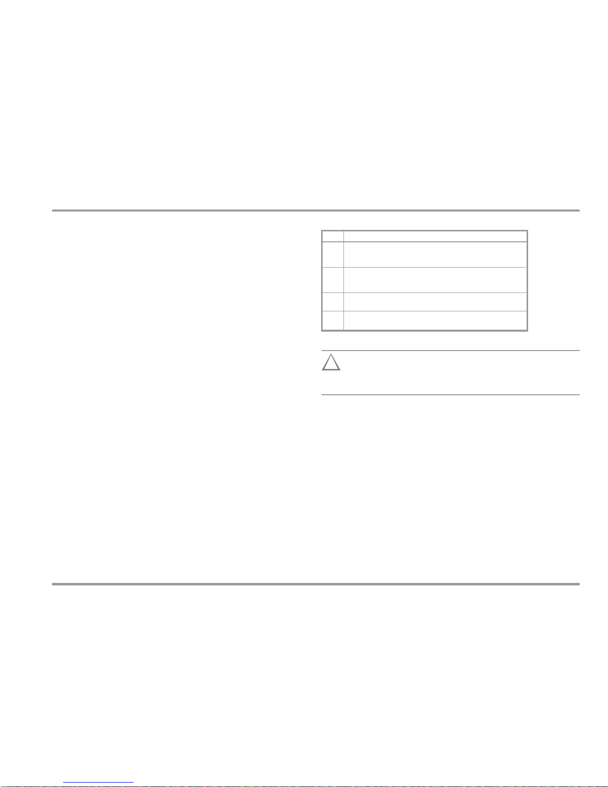
Measuring Categories and their Significance per IEC 61010-1
The measuring instrument is intended for quick, safe
measurement of repaired or modified electrical medical devices
and their components (e.g. applications parts) in accordance with
IEC 62353.
Adherence to technical safety requirements assures safe handling
of electrical medical devices for users of the measuring
instrument. The safety of the patient is also assured during use of
tested electrical medical devices.
Use for Intended Purpose
•
The measuring instrument can be used as a benchtop device
which must be isolated and set up on a solid base while
measurements are being performed.
Only those measurements which are descr ibed in the following
chapters may be performed with the measuring instrument.
The measuring instrument, including the measuring probe,
may only be used within the specified measuring category (see
page 8, as well as the table below regarding significance).
Overload limits may not be exceeded. See technical data on
page 30 for overload values and overload limits.
Measurements may only be performed under the specified
ambient conditions. See page 32 regarding operating temperature range and relative humidity.
The measuring instrument may only be used in accordance
with the specified degree of protection (see page 33).
!
Attention!
The measuring instrument may not be used for
measurements within electrical systems!
•
•
• •
•
BC Biomedical
5
CAT
Definition
I
Measurements in electrical circuits which are not directly connected to
the mains: for example electrical systems in motor vehicles and
aircraft, batteries etc.
II
Measurements in electrical circuits which are electrically connected to
the low-voltage mains: via plug, e.g. in household, office and
laboratory applications
III
Measurements in building installations: stationary power consumers,
distributor terminals, devices connected permanently to the distributor
IV
Measurements at power sources for low-voltage installations:
meters, mains terminals, primary overvoltage protection devices
Page 6
Applications and Classification of Devices Under Test
1.1 Classification of Devices Under Test
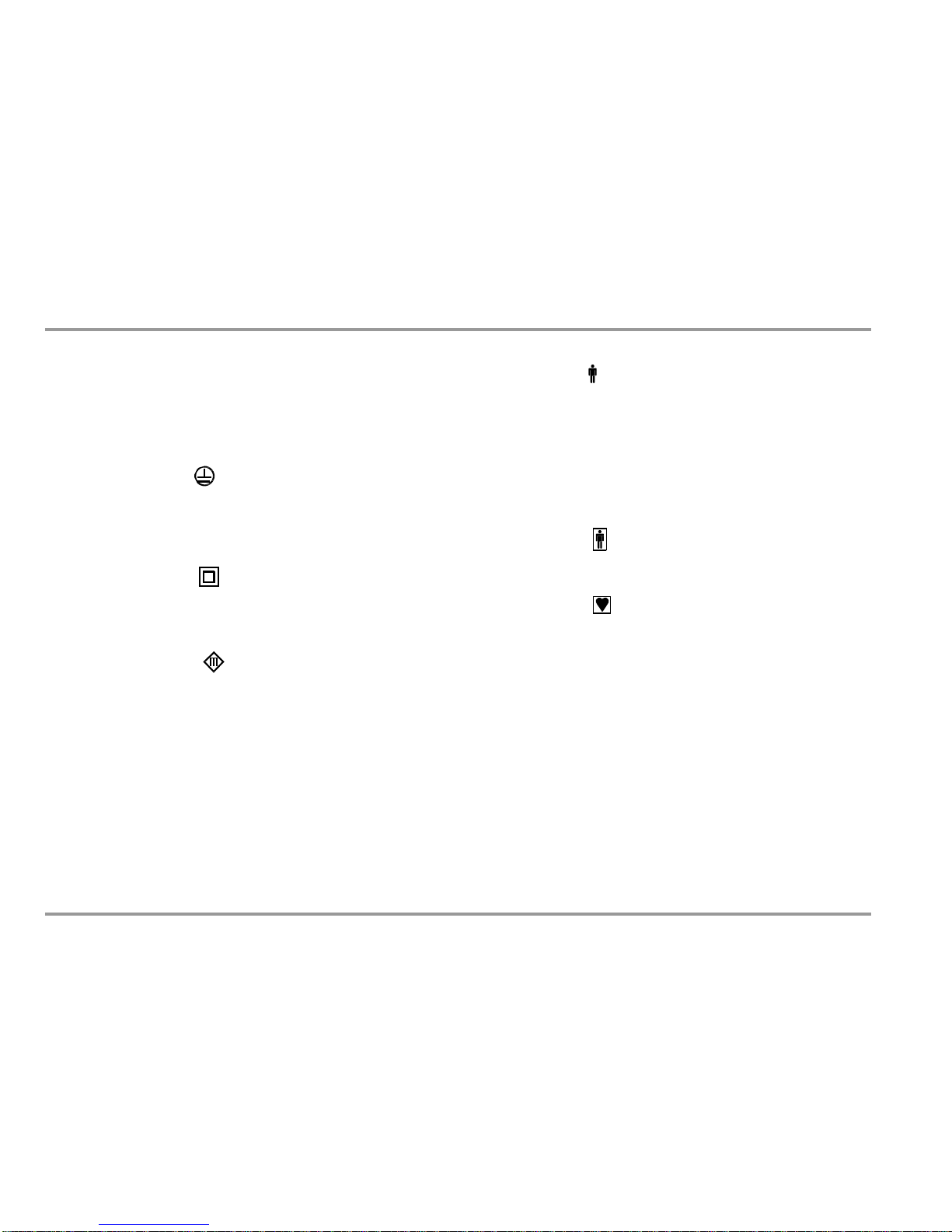
1.1.1 Protection Classes
Devices assigned to all of the following protection classes are
equipped with basic insulation, and provide for protection against
electrical shock by means of various additional precautions as well.
1.1.2 Applied Parts (electrical medical devices)
Type B Applied Parts
(body)
Devices of this type are suitable for both internal and external
patient applications, except for use in direct proximity to the heart.
These devices provide for adequate protection against shock,
especially as regards:
•
Reliable leakage current
•
Reliable protective conductor connection if utilized
Protection Class I Devices
Exposed, conductive parts are connected to the protective
conductor so that they are not charged with voltage if the basic
insulation should fail.
Type BF Applied Parts
(body float)
Same as type B, but with type F insulated applied parts.
Protection Class II Devices
These devices are equipped with double insulation or reinforced
insulation.
Type CF Applied Parts
(cardiac float)
Devices of this type are suitable for use directly at the heart. The
application pa rt may not be grounded.
Protection Class III Devices
These devices are powered with safety extra-low voltage (SELV).
Beyond this, no voltages are generated which exceed SELV.
These devices may not be connected to the mains.
Note: Only a visual inspection can be conducted for devices of this
protection class with the BC Biomedical SA-2500.
6
BC Biomedical
Page 7
Safety Warnings
2 Safety Features and Precautions
Observe the following safety precautions:
•
The instrument may only be connected to electrical supply
systems with which conform to the valid safety regulations
(e.g. IEC 60364, VDE 0100) and are protected with a fuse or
circuit breaker with a maximum rating of 16 A.
Measurements within electrical systems are prohibited.
Be prepared for the occurrence of unexpected voltages at
devices under test (for example, capacitors may be
dangerously charged).
Make certain that the measurement cables are in proper
working condition, e.g. no damage to insulation, no cracks in
cables or plugs etc.
Insulation Resistance Measurement (alternative leakage current):
Testing is conducted with up to 500 V. Current limiting is
utilized (I < 10 mA), but if the terminals (L and N) are touched,
electrical shock may occur which could result in consequential
accidents.
Leakage Current Measurement
It is absolutely essential to assure that the device under test is
operated with line voltage during performance of leakage
current measurements. Exposed conductive parts may
conduct dangerous contact voltage during testing, and may
not under any circumstances be touched (mains power is
disconnected if leakage current exceeds approx. 10 mA).
Function Test
This instrument fulfills the requirements of applicable European
and national EC directives. This is confirmed by means of the CE
mark. A corresponding declaration of conformity can be
requested from BC Biomedical.
The SA-2500 measuring instrument has been manufactured and
tested in accordance with the following safety regulations:
IEC 61010-1 / DIN EN 61010-1 / VDE 0411-1, DIN VDE 0404
IEC 61577 / EN 61577 / VDE 0413 part 1, 2 and 3
When used for its intended purpose, the safety of the user, the
measuring instrument and the device under test (electrical
equipment or electrical medical device) is assured.
Read the operating instructions carefully and completely before placing
your measuring instrument into service. Follow all instructions contained
therein. Make sure that the ope rating instructions are available to all
users of the instrument.
Tests may only be performed by qualified personnel, or under
the supervision and direction of qualified personnel. The user
must be instructed by qualified personnel in the execution and
evaluation of tests.
•
•
•
• •
Note
Manufacturers and importers of electrical medical devices
must provide documentation for the performance of
maintenance by trained personnel.
•
!
Attention!
The function test may only be performed after the DUT has
successfully passed the safety test!
BC Biomedical
7
Page 8
Safety Warnings
•
Power Consumers with High Inrush Current (> 16 A) – Function Test
(e.g. fluorescent tubes, halogen lamps, headlights etc.):
Observe the following instructions in order to prevent
excessive contact loads.
Meanings of Symbols on the Instrument
300 V CAT II
Maximum permissible voltage and measuring category
between connections 1 through 4, the test socket and
ground
I
System with maximum 16 A nominal current
!
Attention!
Starting the Function Test
For reasons of safety, the device under test must be
switched off before the function test is started. This
precaution prevents inadvertent start-up of a device under
test which may represent a hazard during operation, e.g. a
cetrifuge.
Ending the Function Test
After completion of the function test, devices under test
must be turned off with their own switch – especially
devices with motors or other inductive loads.
Warning regarding dangerous electrical voltage
Warning concerning a point of danger
(attention: observe documentation!)
!
Per European Council Directive WEEE
2012/19/EU, do not dispose of this product as
unsorted municipal waste.
The measuring instrument may not be used:
•
•
If it demonstrates visible damage
With damaged connector cables, measuring cables or
patient ports
If it no longer functions properly
•
In such cases, the instrument must be removed from operation
and secured against unintentional use.
8
BC Biomedical
Page 9
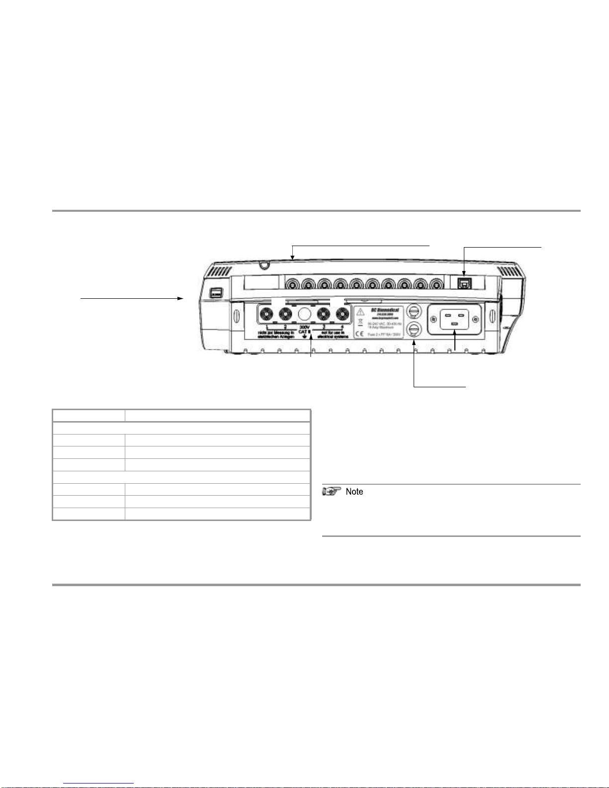
Terminals
3 Terminals
Jacks 1 through 10 for Applied Parts
USB Slave, to PC
1
10
Standard Socket (test socket)
for connecting the DUT
S1 S2
nection
Connections for Probes
Insert the double plug of the probe into sockets 1 and 2 such that
the plug with the white ring makes contact with socket 1 (silver
ring).
If 2 probes are used: If the first probe is, for example, the 25 m cable
drum (1-2), the test point is contacted with the second probe (3-4).
1)
For a lot of measurements, the protective conductor of the
test socket is not connected with the protective conductor
of the mains terminal.
1)
4-wire measurement possible
2)
4-wire measurement not provided for, see ”Measuring and Storing an
Offset Value when Using a 2
nd
Probe” on page 15
BC Biomedical
9
Connection
Application
Top Connections
Standard socket
Test socket
Sockets 1 through 10
Applied parts connection
USB-SI
USB slave, to PC
Bottom Connections
Sockets 1 and 2
Test probe connection (max. 300 V CAT II)
Sockets 3/4 (green)
Terminal for second test probe
2)
(max. 300 V CAT II)
Inlet socket
Connection for supply power (90 to 240 V, 50 to 400 Hz)
Mains Con
Fuses
Page 10
Initial Start-Up – Setup
4 Initial Start-Up
4.1 Connection to the Mains (90 to 240 V, 50 to 400 Hz)
➭
Connect the mains plug at the measuring instrument to the
mains power outlet.
4.1.1 Automatic Recognition of Mains Connection Errors
The measuring instrument’s protective conductor connection is
tested each time the start-stop key is pressed.
If a voltage of greater than 25 V is detected between the
protective conductor and the finger contact, no measurements
are possible. Disconnect the measuring instrument from the
mains immediately in the event of a mains connection error, and
arrange for the error to be corrected!
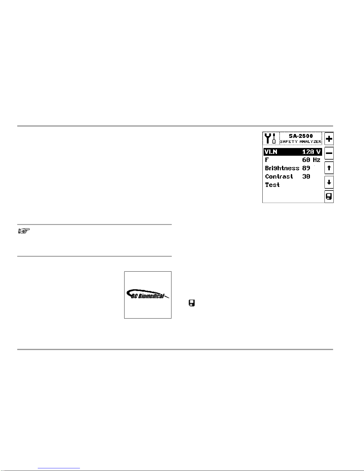
Selecting Nominal Line Voltage VLN
Measured values acquired by
means of leakage current measurement are normalized to the
selected VLN voltage value. Line
voltage parameter VLN (100, 110,
115, 117, 120, 127, 220, 230,
240 or 250 V) can be selected
with the
keys, and adjusted
with the +/– keys. The voltage
value selected here is generated
by the measuring instrument for alternative measurement.
Setting Nominal Frequency
The frequency selected here is generated by the measuring instrument for alternative measurement of leakage cur rent. Nominal
line frequency parameter F (50 or 60 Hz) can be selected with the
keys, and adjusted with the +/– keys. This setting is irrelevant
for direct measurement and differential current measurement.
Setting Brightness and Contrast
Brightness (1 ... 40 ... 100) and contrast (0 ... 40 ... 63) for the LCD panel
can be selected with the
keys, and adjusted with the +/– keys.
Activating Device Parameters
Changed values are permanently saved after acknowledging with
Note
Voltage at the mains protective conductor may cause
erroneous measured values during the measurement of
leakage current.
4.2 Switching the Measuring Instrument On
Initial Window
The initial window shown at the right appears in the event of mains connection.
the key. The display is then switched to the main menu. If the
setup menu is exited with the ESC key, the changed values only remain active until supply power to the instrument is interrupted.
Function Test
For testing the keys, LCD segments and the acoustic warning sig-
nal.
4.3 Configuring Device Parameters – Setup Menu
All of the settings which are required for operation of the
measuring instrument can be entered in the setup menu.
10
BC Biomedical
Page 11
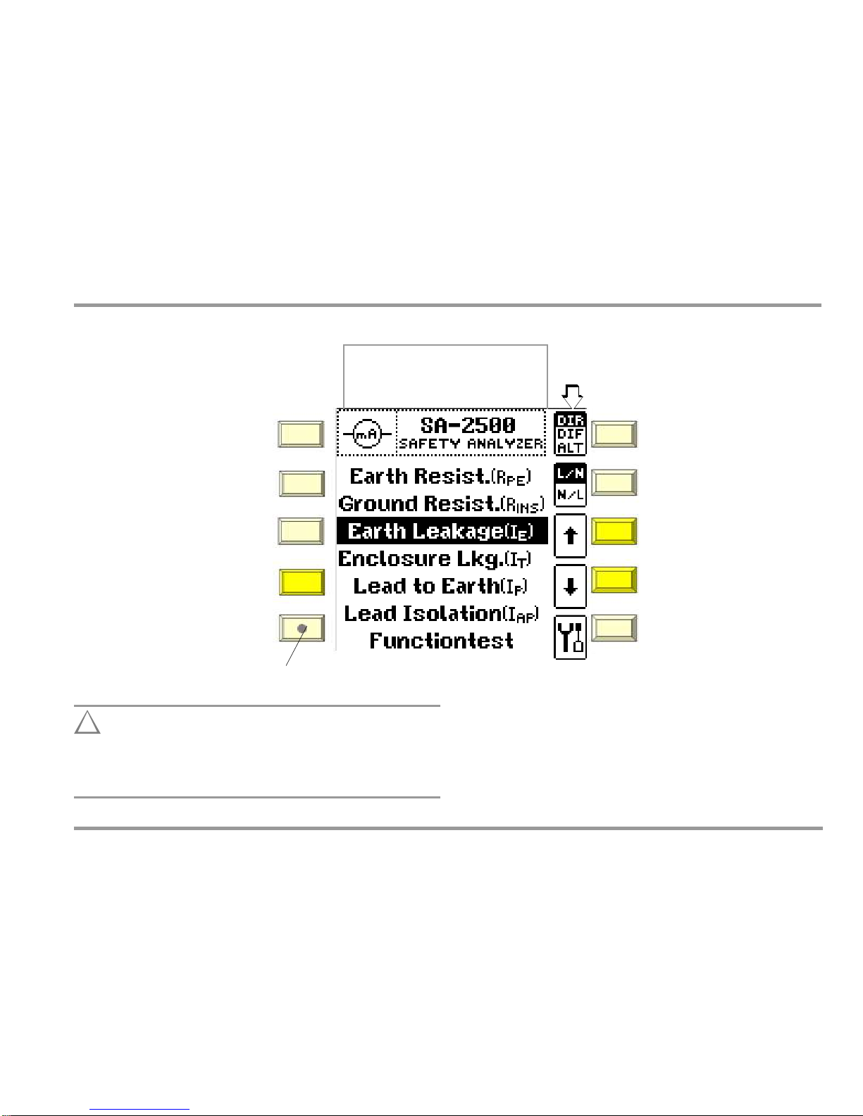
Local Operating Mode
Manual Test
5 Manually Triggered Measurements
Adjustable measuring parameters
are displayed as softkeys.
DIR
DIF
ALT
Direct measurement
Diff. current measurement
Alternative meas. method
PRINT:
Key for hardcopy functions
(in preparation)
L/N
N/L
ESC: Return to previous level
Mains polarity
ARROW
UP HELP:
Access context sensitive help
Select measuring function
ARROW
DOWN:
MENU:
Access the main menu
(R
PE
measuring function)
Select measuring function
STARTSTOP: Start or stop measurement /
function test
SETUP:
Access the setup menu
–
Line voltage
–
Line Frequency
–
LCD brightness
–
LCD contrast
Contact Surface
For finger contact – PE potential check
Main Menu Display
!
Attention!
Remote control of the SA-2500 should always be coordinated
with the user who is in contact with the measuring
instrument at the same time, for example in order to exclude the possibility of contact hazards.
BC Biomedical
11
Operating Mode Display
–
Remote: highlighted display
–
Local: display not highlighted (see below)
Page 12
Local Operating Mode
Manual Test
5.1 General Procedure
5.2 Overview
➭
➭
Select the main menu: MENU key.
Select a menu function:
keys.
Depending upon the measuring function select either
–
Type of test current: DIR / DIF / ALT / DL key.
or
–
Protection class and type of connection: PC1 / PC2 / FIX key.
Connect the device under test in accordance with the
previously selected type of test current.
14
➭
Depending upon the type of test current, it may be necessary to
use the probe.
The device under test is checked for short circuiting for all active
measurements during which the mains are connected to the test
socket (e.g. for leakage current measurements).
➭
Start the test with the STARTSTOP
During measurement, a symbol representing a runner appears
at the upper left-hand corner instead of the measurement icon.
During measurement and after the measurement has been completed, measurement data can be read from the display.
➭
If necessary, repeat the test with reversed mains
power polarity: L/N N/L key.
➭
The display is returned to the main menu by pressing the ESC
key or the MENU key.
26
AP = applied part; PC1/2 = protection class I/II; FIX = permanent connection
12
BC Biomedical
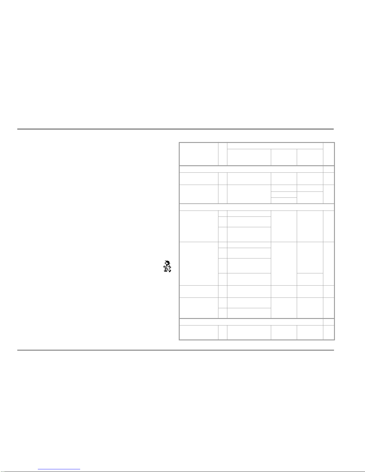
Abbreviation
Measurement Type Parameter
Description
Measured Quantity /
Method
Type of
’Connection
Sockets:
Probe 1–2
AP A ... K
Resistance Measurements
R PE
Protective conductor
resistance
PC1
l
Probe 1–2
Page
R INS
Insulation resistance
PC1
—
Page
16
PC2
l
Probe 1–2
FIX
Leakage Current Measurement
I E
Equipment leakage
current
DIR Direct measurement
Test socket
l
AP A ... K
Probe 1–2
Page
18
DIF
Differential current
measurement
ALT
Alternative measurement
(alternative equipment
leakage current)
I T
Touch current
DIR Direct measurement
Test socket
l
Probe 1–2
Page
20
DIF
Differential Current
Measurement
ALT
Alternative measurement
(alternative equipment
leakage current)
DL
Measurement with 2 probes
(cable drum at 1–2)
Probe 1–2
Probe 3–4
I P
Patient leakage current
DIR
Patient leakage current,
direct
Test socket
l
AP A...K
Page
24
I AP
Applied parts leakage
current
DIR
Direct measurement
(mains at applied part)
Test socket
l
AP A...K
Page
ALT
Alternative measurement
(altern. patient leakage current)
Functions Tests
TEST
Voltage / Load current
Active/apparent power P/A
Power factor PF
Test socket
Page
28
Page 13

This page has been left blank to display the following measurements on opposite pages for better clarity.
BC Biomedical
13
Page 14

R
PE
Protective Conductor Resistance
Measuring Method
Resistance is measured:
•
Between each exposed conductive part of the housing which
is connected to the protective conductor (probe contact) and
the earthing contacts at the mains and the device plug (if a
removable mains connector cable is used).
•
Between the earthing contacts at the mains plug and the
earthing contacts at the device plug for device connector
cables
Test Socket Connection
Applications
Continuity and resistance of the protective conductor must be
measured.
Definition
Protective conductor resistance is the resistance of the
connection of a protection class I device (PC1) between any
exposed conductive parts which are connected to the protective
conductor and the protective contact at the mains plug or the
mains side of the permanent connection.
Protective conductor resistance is the sum of the following
resistances:
The protective conductor of the test socket (which is not
connected with the protective conductor of the mains terminal for this measurement) is permanently connected with
sockets 3 and 4 to which a second probe can be connected.
•
•
•
Connector cable or device connector cable resistance
Contact resistance of the plug and terminal connections
Resistance of the extension cable
14
BC Biomedical
Page 15

R
PE
Protective Conductor Resistance
Measuring and Storing an Offset Value when Using a 2
nd
Probe
When a second probe is used which is connected to sockets 3
and 4, 4-wire measurements are not provided for. However, the
ohmic resistance of the cable for the second probe can be automatically deducted from the measuring result by determining an
offset value. Please proceed as follows to this end:
➭
➭
Start the test: Press the STARTSTOP key.
1
probe: Contact one of the conductive parts of the housing which is con-
nected to the protective conductor with the probe (socket 1–2).
2
probes: A cable drum or extension cable (socket 1–2) is contacted
with the reference point (e.g. overall earth electrode of a unit), the second probe (socket 3-4) is contacted with the test point.
➭
Ð
Connect the two probes to sockets 1 and 2 or 3 and 4,
respectively. The probe extension cable or the probe
cable drum must generally be conne cted with sockets 1
and 2. Contact both probes with the same reference point.
This is equivalent to short-circuiting the two probes. The offset
value established in this way is retained by pressing the key on
the right (only for values < 2 ), displayed briefly and will be
deducted from all future measuring results. You can store this
offset value, see key below.
After measuring the offset value, the latter can be permanently stored with the key on the right so that it is
available after switching the instrument on again.
Press the key on the right for loading a stored offset
value.
During measurement, the connector cable must only be moved to the extent that it is accessible during repair, modification or testing. If a change
in resistance occurs during the manual test step of the continuity test, it
must be assumed that the protective conductor is damaged, or that one
of the connector contacts is no longer in flawless condition.
➭
➭
Measured values are displayed.
End the test: Press the STARTSTOP key.
Read the measured value and compare it with the table of
permissible limit values.
Ð
Examples of Maximum Permissible Limit Values for Protective Conductor
Resistance for Connector Cables with Lengths of up to 5 m
Ð
Cable
Only use this function if you work with extension cables.
When using different extension cables, the procedure
described above must principally be repeated.
Sequence
➭
Select the test:
keys.
➭
Connect the DUT to the test socket and connect the probe.
BC Biomedical
15
Test
Standard
Test current
OpenCircuit
Voltage
R
PE
Housing –
Device Plug
R
PE
Housing –
Mains Plug
Connector
IEC 60601
IEC 61010
Production
Not defined
0.1
0.1
1.1
IEC 62353
(VDE 0751-1)
> 200 mA
4 V < UL <
24 V
1.2 1.3 0.1
VDE 07010702
—
0.3
+ 0.1
for each addi-
tional 7.5 m
Page 16

R
INS
Insulation Resistance
Measuring Method
Protection Class I (PC1)
Insulation resistance is measured between short-circuited mains
terminals and the protective conductor.
Protection Class II (PC2)
Insulation resistance is measured between short-circuited mains
terminals and external conductive parts which can be contacted
with the probe.
Connection of Permanently Installed Protection Class I Devices
!
Attention!
Deactivate the electrical system which supplies power to
the device under test before connecting the test system!
Applications
Insulation resistance must be measured for:
➭
Remove the mains fuses from the device under test and
disconnect neutral conductor N inside the device under test.
Connect the probe to phase conductor L at the device under
test in order to measure insulation resistance.
In order to assure that all insulation which is exposed to line
voltage is tested during this measurement, make sure that
switches, temperature regulators etc. are closed.
Definition
Insulation resistance is active resistance between the electrical
circuits of the device and its exposed conductive parts.
➭
The PE contact of the test socket is connected with the protective conductor of the mains terminal.
16
BC Biomedical
PC1: protection class l
Between L + N and PE
PC2: protection class ll
Between L + N and user accessible conductive parts
Page 17

R
INS
Insulation Resistance
PC1 Connection
PC2 ConnectionI
All switches at the device under test must be set to the on position during measurement of insulation resistance, including
temperature controlled switches and temperature regulators as
well. Measurement must be performed in all program steps for
devices equipped with program controllers.
➭
Start the test: Press the STARTSTOP
!
Attention!
Testing is conducted with up to 500 V. Current limiting is utilized (I < 10 mA), but if the terminals (L and N) are touched,
electrical shock may occur which could result in consequential accidents.
Permanent connection
Note: Open-circuit voltage is always greater than nominal voltage.
➭
PC2 connection: Contact exposed conductive parts with the
probe during measurement.
All measured values are displayed.
End the test: Press the STARTSTOP key.
Read the measured value and compare it with the table of
permissible limit values.
➭
➭
Sequence
Protection class I devices: The protective conductor test must already
have been passed as a prerequisite for the insulation resistance test.
Examples of Minimum Permissible Limit Values for Insulation Resistance
➭
➭
Select the test:
keys.
Select the protection class and the type of connection:
PC1 / PC2 / FIX. key.
Connect the DUT to the test socket, and connect the probe if necessary.
➭
BC Biomedical
17
Test
Standard
Test Voltage
R
ISO
PC I PC II PC II I Heat
IEC 62353
(VDE 0751-1)
500 V
2 M
7 M
70 M
70 M
VDE0701-0702
1 M2 M
0.25 M
0.3 M
Page 18

IE Equipment Leakage Current (differential current – protective conductor current – fault current)
Definition of Alternative Measurement (alternative equipment leakage current)
Alternative leakage current is current which flows through the
active conductors of the device which are connected to each
other (L/N) to the protective conductor, or to the exposed,
conductive parts and the applied parts.
Direct Measurement Method
The device under test is operated with mains power. Current
which flows through the PE conductor to earth at the mains side
of the device connection is measured. The value which has been
adjusted to nominal line voltage is displayed (see section 4.3).
The protective conductor is ineffective during measurement!
Differential Current Measurement Method
The device under test is operated with mains power. The sum of
the momentary values of all currents which flow through all active
conductors (L/N) at the mains side of the device conne ction is
measured. The measurements must be performed with mains
plug polarity in both directions. The value which has been adjusted to nominal line voltage is displayed (see section 4.3).
Alternative Measurement Method (alternative equipment leakage current)
The device under test is tested with the nominal voltage which
has been selected in the setup menu. Current which would flow
with this nominal voltage is displayed.
Type of Test Current Parameter
Applications
Equipment leakage current must be measured for all devices.
Definition of Equipment Leakage Current / Protective Conductor Current
IEC 62353 (VDE 0751-1)
Current which flows from a power pack to ground via the protective conductor, and via exposed conductive parts of the housing
and the applied parts.
Definition of Direct Measurement
Total amount of current which flows through the protective con-
ductor, probe and applied parts in the case of housings which are
isolated from ground.
Definition of Differential Current Measurement
Sum of instantaneous current values which flow via the L and N
conductors at the device mains connection. Differential current is
practically identical to fault current in the event of an error. Fault
current: Current which is caused by an insulation defect, and
which flows via the defective point.
–
DIR
–
DIF
–
ALT
Protective conductor current, direct
Differential current
Alternative equipment leakage current
Mains Polarity Parameter
Polarity can be reversed for tests in accordance with the direct
and differential current methods.
18
BC Biomedical
Page 19

IE Equipment Leakage Current (differential current – protective conductor current – fault current)
Equipment Leakage Current with the Direct Measurement Method
Equipment Leakage Current with the Alternative Measurement Method
Sequence
The protective conductor is ineffective during measurement!
➭
➭
➭
➭
➭
Select the test:
keys.
Connect the DUT to the test socket.
Select type of test current: DIR / DIF / ALT key.
Select mains polarity reversal: L/N / N/L key.
Start the test: Press the STARTSTOP key.
Measured values are displayed.
End the test: Press the STARTSTOP key.
Read the measured value and compare it with the table see bel.
Equipment Leakage Current with the Differential Current Measurement Method
Examples of Maximum Permissible Limit Values for Device Leakage
Current / Protective Conductor Current
BC Biomedical
19
Test Standard
Protection Class
Direct / Differential Cur-
rent Measurement
Alternative Measurement
IEC 60601 3rd ed.
PC1 5 mA 10 mA
IEC 62353
(VDE 0751-1)
PC1 0.5 mA 1 mA
PC2 0.1 mA 0.5 mA
VDE 0701/702
PC1
3.5 mA
PC2
0.5 mA
Page 20

IT Touch Current – Testing for Absence of Voltage
Definition of Touch Current
Leakage current that flows from the housing or parts thereof –
with the exception of the patient ports – with which the user or the
patient may come into contact during use for intended purpose,
to ground or another part of the housing via an external
connection, except for the protective conductor.
Definition of Direct Measurement
Current which flows through the probe in the case of housings
which are isolated from ground.
Definition of Differential Current Measurement
Sum of instantaneous current values which flow via the L and N
conductors at the device mains connection. Differential current is
practically identical to fault current in the event of an error. Fault
current: Current which is caused by an insulation defect, and
which flows via the defective point.
Definition of Alternative Measurement (alternative equipment leakage
current)
Alternative leakage current is current which flows through the
active conductors of the device which are connected to each
other (L/N), to the exposed, conductive parts.
Applications
For protection class I devices, it may be necessary to separately
measure leakage current from exposed conductive parts which
are not connected to the protective conductor.
Only methods direct measurement and differential current measurement can be used for devices for which isolation in the power
pack is not taken into consideration by the measurement (e.g. resulting from a relay which is only closed in the operating state).
Leakage current measurement may only be performed at
protection class I devices after the protective conductor test has
been passed.
The device must be measured in all intended functional states
(e.g. switch positions) which influence leakage current. The
highest acquired value, as well as the corresponding function if
applicable, must be documented. The manufacturer’s
specifications must be adhered to.
20
BC Biomedical
Page 21

IT Touch Current – Testing for Absence of Voltage
Direct Measurement Method
The device under test is operated with mains power. Current
which flows to the protective conductor via exposed conductive
parts is measured. The measurements must be performed with
mains plug polarity in both directions. The AC or the DC component of the current is measured. The value which has been adjusted to nominal line voltage is displayed (see section 4.3).
Mains Polarity Parameter (not for 2-probe Measurement)
Polarity can be reversed for measurements during which the
mains are connected to the test socket.
Direct Measurement Method Differential Current Measurement Method
Make sure that the contacted parts are not grounded.
Differential Current Measurement Method
The device under test is operated with mains power. The sum of
the momentary values of all currents which flow through all active
conductors (L/N) at the mains side of the device connection is
measured. The measurements must be performed with mains
plug polarity in both directions. The value which has been adjusted to nominal line voltage is displayed (see section 4.3).
Alternative Measurement Method
The device under test is tested with the nominal voltage which
has been selected in the setup menu. Current which would flow
with this nominal voltage is displayed.
Type of Test Current Parameter
Alternative Measurement Method
2-probe Measurement Method
–
DIR
–
DIF
–
ALT
– DL
Touch current, direct (with probe)
Differential current, (with probe)
Alternative touch current, (with probe)
Contact current with 2 probes (DL = Dual Lead)
BC Biomedical
21
Page 22

IT Touch Current – Testing for Absence of Voltage
Sequence DIR / DIF / ALT
Procedure for DL – 2-probe Measurement
This measurement is performed with 2 probes. The measuring
section is electrically isolated from the mains power supply of the
instrument. Input resistance is 1 k.
➭
➭
➭
➭
➭
➭
➭
Select the test:
keys.
Connect the DUT to the test socket, or connect the probe.
Select type of test current: DIR / DIF / ALT key.
Select mains polarity reversal: L/N / N/L key.
Start the test: Press the STARTSTOP key.
Measured values are displayed.
End the test: Press the STARTSTOP key.
Read the measured value and compare it with the table of
permissible limit values.
➭
➭
Select test: key
Connect probe 1 (e. g. the 25 m cable drum) to sockets 1-2
and connect the probe tip with the reference measuring point.
Select test current type: key DL
Scan the test point with probe 2 (socket connectors 3-4).
Start test: press key STARTSTOP.
Measured values are displayed.
Quit test: Press key STARTSTOP.
Read off measured value and compare it with the table of per-
missible limit values.
➭
➭
➭
➭
➭
Examples of Maximum Permissible Limit Values for
Touch Current in mA
22
BC Biomedical
Test Standard
Protection
Class
Direct /
Differential Current
Measurement
Alternative Measurement
IEC 62353
(VDE 0751-1)
PC2 0.1 mA
0.5 mA
VDE 0701-702
PC2
0.5 mA
Page 23

This page has been left blank to display the following measurements on opposite pages for better clarity.
BC Biomedical
23
Page 24

IP Patient Leakage Current
When testing measuring instruments with several applied parts,
each must be connected, one after the other, and measuring results must be evaluated on the basis of the limit values. Applied
parts which are not included in the
measurement must be kept potential-free.
Definition of Patient Leakage Current
Current which flows from power packs and exposed conductive
parts of the housing to the applied parts.
The AC and the DC component of the current is measured.
Direct Measurement Method
The device under test is operated with mains power. Current
which flows through the applied parts to earth at the mains side of
the device connection is measured. The value which has been
adjusted to nominal line voltage is displayed (see section 4.3).
Type of Test Current Parameter
Applications
As a rule, measurement of leakage current from the applied part
to PE must be performed in accordance with IEC 60601.
No separate me asurement is normally required for type B
applied parts. The applied parts are connected to the housing
(see figures), and are also measured during housing
leakage current measurement, to which the same permissible
values apply.
Separate measurement of leakage current from type B applied
parts only has to be performed if it is specified by the
manufacturer (see accompanying documentation).
For type BF or CF applied parts, measurement is required for all
interconnected patient ports used for a single function of the
applied part, or measurement must be executed as specified by
the manufacturer.
– DIR
Patient leakage current, direct (applied parts plugged in)
Mains Polarity Parameter
Polarity can be reversed for measurements during which the
mains are connected to the test socket.
24
BC Biomedical
Page 25

IP Patient Leakage Current
Examples of Maximum Permissible Limit Values for Patient Leakage
Current in mA
Sequence
➭
➭
Select the test:
keys.
Connect the device under test to the test socket, and the
applied parts to the patient ports. The test probe has to be
connected but without applying electrical contact (potentialfree).
Select mains polarity reversal: L/N / N/L key.
Select applied parts 1 through 10: key.
Start the test: Press the STARTSTOP key.
Measured values are displayed.
End the test: Press the STARTSTOP key.
Read the measured value and compare it with the table of
permissible limit values.
➭
➭
➭
➭
➭
BC Biomedical
25
Test Standard
I
P
Type B
Type BF
Type CF
NC SFC NC SFC NC SFC
EN 60601
DC
0.01 0.05 0.01 0.05 0.01 0.05 AC 0.1 0.5 0.1 0.5 0.01 0.05
IEC 60601 3rd ed.
Total Patient
Leakage Current
DC
0.05 0.1 0.05 0.1 0.05 0.1
AC 0.5 1 0.5 1 0.05 0.1
Page 26

I
AP
Leakage Current from the Applied Part (alternative patient leakage current, mains at applied part)
tient ports for a type BF or CF applied part.
Definition of Alternative Measurement
Alternative patient leakage current is current which flows through
the conductors of the device which are connected to each other
(L/N/PE) to the patient ports.
Prerequisites:
A high-impedance power supply is connected between one
patient port at a time, and the exposed metallic parts of the
housing (which are connected to each other). The mains terminals
are short-circuited and are connected to the same point on the
housing.
Direct Measurement Method (mains at applied part)
The current which flows over the insulation of the device under
test is measured separately for each applied part.
The device under test is operated with mains power in this case.
The value which has been adjusted to nominal line voltage is displayed (see section 4.3).
Alternative Measurement Method (alternative patient leakage current)
The current which flows over the insulation of the device under
test is measured separately for each applied part.
Measurement is always performed using an AC source with
current limiting. Differing mains voltages are taken into
consideration.
Type of Test Current Parameter
Applications
This measurement is only performed for types BF and CF applied
parts. For type BF and CF applied parts, measurement is required
for all interconnected patient ports used for a single function of
the applied part, or measurement must be executed as specified
by the manufacturer.
When testing measuring instruments with several applied parts,
each must be connected, one after the other, and measuring results must be evaluated on the basis of the limit values shown in
table 2. Applied parts which are not included in the measurement
must be kept potential-free.
Definition of Leakage Current from the Applied Part
Current which flows from power packs and exposed conductive
parts of the housing to the applied parts.
Definition of Direct Measurement
Current which is caused by an undesired interference voltage at
the patient, and which flows from the patient to ground via the pa-
–
DIR
–
ALT
Mains at applied part (applied parts plugged in)
Eq. patient leakage current (applied parts plugged in)
26
BC Biomedical
Page 27

I
AP
Leakage Current from the Application Part (alternative patient leakage current, mains at applied part)
Mains Polarity Parameter
Polarity can be reversed for measurements during which the
mains are connected to the test socket.
Can only be used for types BF and CF applied parts.
➭
➭
Select the test:
keys.
Connect the device under test to the test socket and the applied parts to the patient ports. The test probe has to be connected but without applying electrical contact (potential-free).
Select type of test current: DIR / ALT key.
Select mains polarity reversal: L/N / N/L key.
Select applied parts 1 through 10: key.
Start the test: Press the STARTSTOP key.
Measured values are displayed.
End the test: Press the STARTSTOP key.
Read the measured value and compare it with the table of
permissible limit values.
➭
➭
➭
➭
➭
➭
➭
Examples of Maximum Permissible Limit Values for Leakage
Current in mA
BC Biomedical
27
Test Standard
AP
Direct Measurement
(mains at AP)
Alternative Measurement
(alternative patient leakage
current)
IEC 62353
(VDE 0751-1)
BF 5 mA 5 mA
CF 0.05 mA
0.05 mA
IEC 60601
BF 5 mA —
CF 0.05 mA —
IEC 60601 3rd ed.
Total Patient
Leakage Current
BF 5 mA —
CF 0.1 mA —
Page 28

Function Test with Line Voltage
Measuring Method
The device under test can be subjected to a function test with line
voltage via the integrated test socket.
The function test includes the following measurements:
–
–
–
–
–
Voltage VLN between the L and N conductors
Load current I
L
Active power P
Apparent power S (calculated)
Power factor PF (calculated cos , display > 10 W)
Power factor is calculated from active power and apparent power.
Power factor corresponds to cos for sinusoidal quantities (line
voltage and load current).
Applications
Functions which are relevant with regard to device safety must be
tested in accordance with the manufacturer’s recommendations,
if necessary with the support of a person who is familiar with
operation of the measuring instrument or measuring system.
Test Socket Connection
Refer to BC Biomedical function testers and light analyzers for
further function tests.
28
BC Biomedical
Page 29

Function Test with Line Voltage
Prerequisites
•
It is only permissible to execute the function test after the
device under test has passed the safety test, i.e. all safety
measurements must first be executed and passed.
The device under test must be connected to the test socket.
If no device under test has been connected, momentary line
voltage are measured if the measuring
instrument is connected to the mains.
No short-circuits may exist at the DUT.
•
•
!
Attention!
Starting the Function Test
For reasons of safety, the device under test must be
switched off before the function test is started. This
precaution prevents inadvertent start-up of a device under
test which may represent a hazard during operation, e.g. a
centrifuge.
Ending the Function Test
After completion of the function test, devices under test
must be turned off with their own switch – especially
devices with motors or other inductive loads.
Sequence
➭
➭
➭
Select the test:
keys.
Connect the DUT to the test socket.
Start the test: Press the STARTSTOP key.
All measured values are displayed.
End the test: Press the STARTSTOP key.
BC Biomedical
29
Page 30

Technical Data
6 Technical Data
(2.5% rdg. + 1 d)
(2.5% rdg. + 1 d)
monit
1)
Remote control: 40 ... 200 Hz
2)
Remote control: 100 ... 500 V
30
BC Biomedical
Measured
Quantity
Measuring Range
/ Nominal Range
of Use
Reso-
lution
Additional
Info
OpenCircuit
Voltage
U
0
Addi-
tional
Info
ShortCircuit
Current
I
K
Int.
Resist.
R
I
Ref.
Resist.
R
REF
Measuring Error
Intrinsic Error
Overload
Capacity
Value Time
R
PE
Protective earth
resistance
man: 1
...
999 m
man: 0.01
...
9.99
1 m
10 m
Electronic
fuse + fuse
link
4.0 4.5 V
AC TRMS
where I
PE
= 200
mA~
where
48 Hz
1)
220 ...
270 mA
AC TRMS
—
—
10 % rdg.
within a rage of
0.1 ... 10
for IP = 200 mA
(2.5% rdg. + 10 m)
within a rage of
0.1 ... 10
where IP = 200 mA
240 V
AC/DC
Cont.
auto: 0.01
...
30.00
0.01 ... 3.30
0.1 ... 10.0
10 m
10 m
100 m
R
INS
Insulation
resistance
10
...
300 k
10 k
Test
voltage:
500 V DC
2)
UN < U <
1.2 U
N
Nominal
current
> 1 mA
where
R
ISO
=
500 k
2 mA
—
—
0.01 ... 100 M:
10% rdg.
> 100 M
20% rdg.
where UP = 500 V
each
0.1 ... 30 M:
(2.5% rdg. + 1 d)
> 30 M
(5 % rdg. + 1 d)
where UP = 500 V
each
240 V
AC/DC
Cont.
0.01
...
3.0 M
10 k
0.1
...
30.0 M
100 k
1
...
300 M
1 M
Leakage Current Measurements – Direct Method (DIR/DL)
I
E
Equipment
leakage current
10
...
300 A
0.01
...
3.00 mA at
0.1
...
30.0 mA at
1 A
10 A
100 mA
= Protective earth current, direct (between L and N)
Residual current monitoring,
Mains shutdown: > 20 mA~ (25 ms)
0.5
...
20.0 mA:
10% rdg.
20
...
300 A:
(5% rdg. + 1 d)
> 300 A:
240 V
AC/DC
Cont.
I
T
Touch current
10
...
300 A
0.01
...
3.00 mA at
1.1
...
30.0 mA at
1 A
10 A
100 A
Probe current monitoring:
Probe shutdown: IT > 10 mA~ (5 ms)
Residual current monitoring
Mains shutdown: I
DIF
> 10 mA~ (25 ms)
1 k
10
—
1.2
...
10 mA at:
10% rdg.
20
...
300 A at:
(5% rdg. + 1 d)
> 300 A at:
240 V
AC/DC
Cont.
I
P
Patient leakage
current
2
...
300 A
0.01
...
3.00 mA at
1 A
10 A
Probe current monitoring:
Probe shutdown: IP > 10 mA~ (5 ms)
Residual current oring
Mains shutdown: I
DIF
> 10 mA~ (25 ms)
1 k
10
—
0.01
...
3 mA at:
10% rdg.
10
...
300 A at:
(7.5% rdg. + 1 d)
0.30
...
3.00 mA at
±(2.5% rdg. + 1 d)
240 V
AC/DC
Cont.
I
AP
Applied parts
leakage current
10
...
300 A~
0.01
...
3.00 mA~
0.1
...
30.0 mA~
1 A
10 A
100 mA
Test
voltage:
110/220/
230/240 V
AC
110 ... 240 V~
–15 /
+10%
Fre-
quency
50/60/
200/400
Hz
< 1.5 mA
> 150
k
1 k
10
20 A
...
15 mA AC:
10% rdg.
> 15.0 mA AC:
15% rdg.
20 A
...
15 mA AC:
(5% rdg. + 1 d)
> 15.0 mA AC:
(10% rdg. + 1 d)
240 V
AC/DC
Cont.
Page 31

Technical Data
(10% rdg. + 1 d)
temperature > 70 C
f < 100 Hz
f 100 Hz
f < 100 Hz
3)
Remote control: 50 ... 400 Hz
BC Biomedical
31
Measured
Quantity
Measuring Range
/ Nominal Range
of Use
Reso-
lution
Addi-
tional
Info
OpenCircuit
Voltage
U
0
Addi-
tional
Info
ShortCircuit
Current
I
K
Int.
Resist.
R
I
Ref.
Resist.
R
REF
Measuring Error
Intrinsic Error
Overload
Capacity
Value Time
Leakage Current Measurements – Differential Method (DIF)
I
E
I
T
Residual current
between L and N
10
...
300 A~
0.01
...
3.00 mA~
0.1
...
30.0 mA
1 A
10 A
100 A
= Protective earth current, direct
Residual current monitoring
Mains shutdown: > 20 mA~ (25 ms)
0.5
...
20.0 mA:
10% rdg.
20
...
300 A:
(5% rdg. + 1 d)
> 300 A:
(2.5% rdg. + 1 d)
240 V
AC/DC
Cont.
Leakage Current Measurements – Alternative Method: Alternative leakage current (ALT)
I
E
I
T
I
AP
2
...
300 A~
0.01
...
3.00 mA~
0.1
...
30.0 mA~
1 A
10 A
100 A
Test
voltage:
110/220/
230/240 V
AC
110 ... 240
V~
–15 /
+10%
Fre-
quency
50/60 Hz
3)
< 1.5 mA
> 150
k
1 k
10
20 A
...
15 mA AC:
10% rdg.
> 15.0 mA AC:
15% rdg.
20 A
...
15 mA AC:
(5% rdg. + 1 d)
> 15.0 mA AC:
240 V
AC/DC
Cont.
Function test
VLN
Line voltage (RMS)
90 ... 240 V AC
(50 ... 400 Hz)
0.1 V
5.0% rdg.
(2.5% rdg. + 1 d)
240 V
AC
Cont.
I
V
Load current
(RMS)
0.02 ... 16.00 A AC
(50 ... 400 Hz)
10 mA
Shutdown by mains relay at: IV > 16 A~ where t > 0.5 s
Shutdown by mains relay at: IV > 4 A~ where internal
5.0% rdg.
(2.5% rdg. + 1 d)
4 A
Cont.
P
Active power
10 ... 4000 W
1 W
Measured value P and calculated value S are compared, and
the smaller of the two is displayed.
Shutdown at internal temperature > 70 C
f < 100 Hz
7.5% rdg.
P > 10 W, PF > 0,5
(5% rdg. + 10 d)
<1000W
<4000W
Cont.
10 min
f 100 Hz
10% rdg.
P > 10 W, PF > 0,5
(7.5% rdg. + 10 d)
S
Apparent power
10 ... 4000 W
1 VA
Calculated vale U
L–N
•
I
V
Shutdown at internal temperature > 70 C
f < 100 Hz
7.5% M
P > 10 W
f < 100 Hz
(5% rdg. + 10 d)
<1000W
<4000W
Cont.
10 min
f 100 Hz
10% rdg.
P > 10 W
f 100 Hz
(7.5% rdg. + 10 d)
LF
Power factor
with sinusoidal
waveshape: cos
0.00 ... 1.00
inductive
0.01
Calculated value P / S, display as of P > 10 W
f < 100 Hz
7.5% M
P > 10 W, PF > 0.5
(5% rdg. + 10 d)
—
—
f 100 Hz
10% rdg.
P > 10 W, PF > 0.5
f 100 Hz
(7.5% rdg. + 10 d)
Page 32

Technical Data
Reference Conditions
Line voltage
Line frequency
Waveshape
Influencing Quantities and Influence Error
230 V 0.2%
50 Hz 0.1%
Sine (deviation between effective and
rectified value < 0.5%)
70 to 77 °F
40 60%
Linear
Ambient temperature
Relative humidity
Load resistance
Ambient Conditions
Operating temperature
Accuracy range
Storage temp. range
Relative humidity
Elevation
Deployment
-32 F... + 104 F
-32 F... + 104 F
– 4 F ... + 140 F
max.75%, no condensation allowed
max. 2000 m
Indoors, except within specified ambient
conditions
Power Supply
Broad Range Variable Power Pack
Line voltage
Line frequency
Power consumption
90 ... 240 V
50 Hz ... 400 Hz
Measuring Leakage Current
Frequency response is
taken into consideration in accordance
with the diagram to the
right when
leakage current is
measured.
Internal consumption
Permissible DUT power consumption
Permissible DUT power consumption, cont. operation
< 20 VA
4000 VA
1000 VA
Permissible DUT current consumption, cont. operation 4 A~
Switching capacity
16 A, AC1 max. 20 A / 600 ms
32
BC Biomedical
U(
f
)
U(
f
=10
)
at
i
ve
M
a
gni
t
ud
e
(dB):
20
l
og
+20
0
–20
–40
–60
10
10
2 103 104 105 106
Rel
Frequency (f) in Hz
Influencing Quantity /
Sphere of Influence
Designation per
IEC 61557
Influence Error
% of Measured Value
Test instrument position
E1 2.5 at I PE (diff)
Test instrument supply voltage
E2 1
Ambient temperature
(-32 F... + 104 F)
E3
1
DUT current consumption
E4 2.5 Low frequency magnetic fields
E5 3.0 at I PE (diff)
DUT impedance
I6 2.5
Conductance leakage capacity
during insulation measurement
E7
0.5
Waveshape of the measured test
current
E8
2.5 at I PA
1 Other measuring ranges
Page 33

Technical Data
Electrical Safety
Fuses
Mechanical Design
Display
2 x FF (UR) 500 V/16 A AC;
6.3 mm x 32 mm;
(BC80-00829)
50 kA breaking capacity at 500 V AC
monochrome backlit dot matrix display,
128 x 128 pixels
(W x D x H) 325 x 250 x 90 mm
approx. 2 kg
Housing: IP 40, connections: IP 20
per DIN VDE 0470 part 1/EN 60529
Dimensions
Weight
Protection
Safety class
Nominal voltage
Test voltage
Measuring category
Fouling factor
Safety Shutdown
Disconnection from mains per SC II
230 V
2.2 kV AC or 3.3 kV DC
300 V CAT II
2
With following differential current at DUT
during:
Table Excerpt Regarding Significance of the
IP Code
penetration by water
–
Function test
–
Touch current meas.
10 mA~ / < 25 ms
direct current meas. 10 mA~ / < 25 ms
Residual current meas. 20 mA~ / < 25 ms
–
Protective conductor
direct current meas. 10 mA~ / < 25 ms
Residual current meas. 20 mA~ / < 25 ms
with following probe current during:
–
Touch current meas. 10 mA~ / < 5 ms
–
Protective conductor
resistance measurement 300 mA~ / < 1ms
Data Interface
USB Slave
Electromagnetic Compatibility, EMC
Interference Emission EN 61326-1:2006 class B
Interference Immunity EN 61326-1:2006
BC Biomedical
33
IP XY
(1
st
digit X)
Protection against pene-
tration of solid particles
IP XY
(2
nd
digit Y)
Protection against
0 Not protected
0 Not protected
1
50.0 mm dia.
1 vertically falling drops
2
12.5 mm dia.
2
vertically falling drops with
enclosure tilted 15
3
2.5 mm dia.
3 spraying water
4
1.0 mm dia.
4 Splashing water
Page 34

Maintenance – Calibration
7 Maintenance and Calibration
7.1 Housing Maintenance
No special maintenance is required for the housing. Keep outside
surfaces clean. Use a slightly dampened cloth for cleaning. Avoid
the use of cleansers, abrasives or solvents.
7.2 Replacing the Fuses
All fuses are accessible from the outside.
If a fuse should blow, eliminate the cause of overload before
placing the instrument back into service!
and great temperature fluctuations, we recommend a relatively
short calibration interval of 1 year.
During recalibration* in an accredited calibration laboratory
(DIN EN ISO/IEC 17025) the deviations of your instrument in relation to traceable standards are measured and documented. The
deviations determined in the process are used for correction of
the readings during subsequent application.
!
Attention!
Disconnect the instrument from the measuring circuit before
removing the fuse!
!
Attention!
Use specified fuses only!
If fuses with other blowing characteristics, other current
ratings or other breaking capacities are used, the operator
is placed in danger, and protective diodes, resistors and
other components may be damaged.
The use of repaired fuses or short-circuiting the fuse holder
is prohibited.
By having your measuring instrument calibrated regularly, you fulfill the requirements of a quality management system per
DIN EN ISO 9001.
Standards DIN VDE 0701-0702 and IEC 63353 (VDE 0751) stipulate that only measuring instruments which are regularly tested
and calibrated may be used for testing.
7.3 Recalibration
The respective measuring task and the stress to which your mea-
suring instrument is subjected affect the ageing of the components and may result in deviations from the guaranteed accuracy.
*
Verification of specifications or adjustment services are not part of the
calibration. For products from our factory, however, any necessary adjustment is frequently performed and the observance of the relevant
specification is confirmed.
If high measuring accuracy is required and the instrument is frequently used in field applications, combined with transport stress
34
BC Biomedical
Page 35

Maintenance – Calibration
7.4 Manufacturer’s Guarantee
The measuring instrument BC Biomedical SA-2500 is guaranteed for
a period of 1 year after date of shipment. The manufacturer’s
guarantee covers materials and workmanship. Damages resulting
from use for any other than the intended purpose, as well as any
and all consequential damages, are excluded.
Calibration is guaranteed for a period of 12 months.
The manufacturer’s guarantee expires if the seal has been
damaged.
7.5 Return and Environmentally Sound Disposal
We identify our electrical and electronic devices in ac-
cordance with WEEE 2012/19/EU and ElektroG using
the symbol shown at the right per DIN EN 50419.
These devices may not be disposed of with the trash.
Please contact our service department regarding the return of old
devices (see page 3).
BC Biomedical
35
Page 36

36
BC Biomedical
Page 37

Index
8
A
Index
Maintenance
Housing
......................................................... 34
Manufacturer’s Guarantee
...................................35
Measuring Categories and their Significance
.......5
O
Overview
Individual Measurements (manual test)
...... 12
P
Patient Leakage Current
Limit Values
.................................................. 25
Product Support
......................................................2
Protective Conductor Resistance
Limit Values
.................................................. 15
R
Recalibration
.........................................................34
Recalibration Service
..............................................3
Repair and Replacement Parts Service
.................3
S
Safety Precautions
..................................................7
Scope of Delivery
....................................................2
Symbols
On Devices Under Test
.................................. 6
On the Instrument
.......................................... 8
T
Terminals
Overview
......................................................... 9
Touch Current
Limit values
.................................................. 22
Training
...................................................................2
U
Use for Intended Purpose
...................................... 5
Accessories
............................................................ 2
C
Classification of Devices Under Test
According to Application Part
.........................6
According to Safety Class
..............................6
Configuring Device Parameters
........................... 10
E
Equipment Leakage Current
Limit Values
..................................................19
F
Frequency Response
........................................... 32
Function Test
........................................................ 28
Fuses
Position
............................................................9
Replacing the Fuses
.....................................34
Technical Data
..............................................33
I
Individual Measurements
General Procedure
........................................12
Initial Window
....................................................... 10
Insultation Resistance
Limit Values
..................................................17
L
Leakage Current from the Application Part
Limit Values
..................................................27
M
Mains Connection Error
....................................... 10
BC Biomedical
37
Page 38

38
BC Biomedical
Page 39

BC Biomedical
39
Page 40

Phone 1-800-242-8428
1-314-638-3800
E-Mail info@bcgroupintl.com
Web
www.bcgroupstore.com
BC Biomedical
3081 Elm Point industrial Drive
St. Charles, MO 63301
09-15 Rev 03
LM-7339-UM
3-349-444-74
Edited in USA • Subject to change without notice • PDF version available on the Internet
 Loading...