


DEFIBRILLATOR
ANALYZERS
DA-2006
DA-2006P
W/ PACER
ANALYZER
SERVICE MANUAL

BC BIOMEDICAL
SERVICE MANUAL
DA-2006 SERIES
TABLE OF CONTENTS
WARNINGS, CAUTIONS, NOTICES ............................................................................... |
ii |
MANUAL REVISIONS..................................................................................................... |
iv |
WARRANTY.................................................................................................................... |
iv |
MANUALS |
|
DA-2006 Series User Manual (Rev 06) ............................................. |
SECTION A |
DA-CS-06 (Rev 02) ........................................................................... |
SECTION A |
OPERATIONAL THEORY.............................................................................. |
SECTION B |
VALIDATION / CALIBRATION ....................................................................... |
SECTION C |
PARTS ........................................................................................................... |
SECTION D |
This Service Manual covers the following units:
•DA-2006
•DA-2006P
i

CAUTION - SERVICE
The DA-2006 Series Analyzers are intended to be serviced only by authorized service personnel.
Troubleshooting and service procedures should only be performed by qualified technical personnel.
WARNING - MODIFICATIONS
The DA-2006 Series Analyzers are intended for use within the published specifications. Any application beyond these specifications or any unauthorized user modifications may result in hazards or improper operation.
ii

NOTICE – DISCLAIMER
USER ASSUMES FULL RESPONSIBILITY FOR UNAUTHORIZED
EQUIPMENT MODIFICATIONS OR APPLICATION OF EQUIPMENT
OUTSIDE OF THE PUBLISHED INTENDED USE AND
SPECIFICATIONS. SUCH MODIFICATIONS OR APPLICATIONS
MAY RESULT IN EQUIPMENT DAMAGE OR PERSONAL INJURY.
NOTICE – DISCLAIMER
BC GROUP INTERNATIONAL, INC. RESERVES THE RIGHT TO
MAKE CHANGES TO ITS PRODUCTS OR SPECIFICATIONS AT
ANY TIME, WITHOUT NOTICE, IN ORDER TO IMPROVE THE
DESIGN OR PERFORMANCE AND TO SUPPLY THE BEST
POSSIBLE PRODUCT. THE INFORMATION IN THIS MANUAL HAS
BEEN CAREFULLY CHECKED AND IS BELIEVED TO BE
ACCURATE. HOWEVER, NO RESPONSIBILITY
IS ASSUMED FOR INACCURACIES.
NOTICE – CONTACT INFORMATION
BC BIOMEDICAL
BC GROUP INTERNATIONAL, INC.
PO BOX 25125
9415 GENTRY AVE
ST. LOUIS, MO 63125
USA
1-800-242-8428
314-638-3800
www.bcgroupintl.com sales@bcgroupintl.com
Service Manual DA-2006 Series |
Copyright © 2007 |
www.bcgroupintl.com |
Made in the USA |
5/07 |
Rev 02 |
|
iii |

MANUAL REVISIONS
Revision # |
Engineering # |
Revisions Made |
Rev 01 |
7395 |
Origination |
Rev 02 |
395 |
Drawing scans inserted |
LIMITED WARRANTY
WARRANTY: BC GROUP INTERNATIONAL, INC. WARRANTS ITS NEW PRODUCTS TO BE FREE FROM DEFECTS IN MATERIALS AND WORKMANSHIP UNDER THE SERVICE FOR WHICH THEY ARE INTENDED. THIS WARRANTY IS EFFECTIVE FOR TWELVE MONTHS FROM THE DATE OF SHIPMENT.
EXCLUSIONS: THIS WARRANTY IS IN LIEU OF ANY OTHER WARRANTY EXPRESSED OR IMPLIED, INCLUDING, BUT NOT LIMITED TO ANY IMPLIED WARRANTY OF MERCHANTABILITY OR FITNESS FOR A PARTICULAR PURPOSE.
BC GROUP INTERNATIONAL, INC. IS NOT LIABLE FOR ANY INCIDENTAL OR CONSEQUENTIAL DAMAGES.
NO PERSON OTHER THAN AN OFFICER IS AUTHORIZED TO GIVE ANY OTHER WARRANTY OR ASSUME ANY LIABILITY.
REMEDIES: THE PURCHASER'S SOLE AND EXCLUSIVE REMEDY SHALL BE: (1) THE REPAIR OR REPLACEMENT OF DEFECTIVE PARTS OR PRODUCTS, WITHOUT CHARGE. (2) AT THE OPTION OF BC GROUP INTERNATIONAL, INC., THE REFUND OF THE PURCHASE PRICE.
P:\Manuals\BCGroup\…\DA-2006_Series_SM_Rev02.doc
iv

SECTION A
USER MANUAL DA-2006 SERIES REV 06
DEFIBRILLATOR
ANALYZERS
DA-2006
DA-2006P
W/ PACER
ANALYZER
USER MANUAL

BC BIOMEDICAL |
|
DA-2006 SERIES |
|
TABLE OF CONTENTS |
|
WARNINGS, CAUTIONS, NOTICES ........................................................................... |
2 |
DESCRIPTION............................................................................................................. |
7 |
OVERVIEW.................................................................................................................. |
15 |
DEFIBRILLATOR ANALYZER ..................................................................................... |
23 |
MAIN SCREEN.................................................................................................. |
23 |
ECG WAVEFORMS SCREEN .......................................................................... |
31 |
PLAYBACK LAST PULSE SCREEN ................................................................. |
35 |
START CHARGE TIMER SCREEN .................................................................. |
37 |
PRINT HEADER................................................................................................ |
39 |
SELF TEST WAVEFORM ................................................................................. |
41 |
RUNNING A DEFIBRILLATION TEST .............................................................. |
43 |
INTRODUCTION .................................................................................... |
43 |
DEFIBRILLATION TEST......................................................................... |
45 |
CARDIOVERSION TEST........................................................................ |
49 |
CHARGE TIME TEST............................................................................. |
53 |
SHOCK ADVISORY ALGORITHM TEST ............................................... |
55 |
TRANSCUTANEOUS PACEMAKER ANALYZER ....................................................... |
57 |
PACE MAIN SCREEN ...................................................................................... |
57 |
PACER MODE SETUP SCREEN...................................................................... |
63 |
SENSITIVITY TEST .......................................................................................... |
65 |
REFRACTORY PERIOD TEST ......................................................................... |
67 |
PRINT MENU SCREEN .................................................................................... |
69 |
PLAYBACK LAST PULSE SCREEN ................................................................. |
71 |
1
DA-2006 Series |
|
MESSAGES ................................................................................................................. |
73 |
SYSTEM SETUP.......................................................................................................... |
75 |
POWER UP SETTINGS............................................................................................... |
77 |
AUTO SEQUENCE FUNCTION................................................................................... |
79 |
VIEW MODE ..................................................................................................... |
81 |
RUN MODE...................................................................................................... |
85 |
PROGRAMMING AUTO SEQUENCES ....................................................................... |
95 |
MANUAL REVISIONS................................................................................................ |
107 |
WARRANTY............................................................................................................... |
107 |
SPECIFICATIONS ..................................................................................................... |
109 |
NOTES....................................................................................................................... |
115 |
2

DA-2006 Series
WARNING - USERS
The DA-2006 Series Analyzers are for use by skilled technical personnel only.
WARNING - USE
The DA-2006 Series Analyzers are intended for testing only and they should never be used in diagnostics, treatment or any other capacity where they would come in contact with a patient.
WARNING - MODIFICATIONS
The DA-2006 Series Analyzers are intended for use within the published specifications. Any application beyond these specifications or any unauthorized user modifications may result in hazards or improper operation.
WARNING - CONNECTIONS
All connections to patients must be removed before connecting the Device Under Test (DUT) to the Analyzer. A serious hazard may occur if the patient is connected when
testing with the Analyzer.
Do not connect any leads from the patient directly to the Analyzer or DUT.
WARNING - POWER ADAPTOR
Unplug the Power Adaptor before cleaning the surface of the Analyzer.
WARNING - LIQUIDS
Do not submerge or spill liquids on the Analyzer. Do not operate the Analyzer if internal components not intended for use with fluids may have been exposed to fluid, as the internal leakage may have caused corrosion and be a potential hazard.
3
DA-2006 Series
CAUTION - SERVICE
The DA-2006 Series Analyzers are intended to be serviced only by authorized service personnel.
Troubleshooting and service procedures should only be performed by qualified technical personnel.
CAUTION - ENVIRONMENT
The DA-2006 Series Analyzers are intended to function between 15 and 40 °C.
Exposure to temperatures outside this range can adversely affect the performance of the Analyzer.
CAUTION - CLEANING
Do not immerse. The Analyzer should be cleaned by wiping gently with a damp, lint-free cloth.
CAUTION - INSPECTION
The DA-2006 Series Analyzers should be inspected before each use for wear and the Analyzer should be serviced
if any parts are in question.
NOTICE – SYMBOLS
Symbol Description
Caution
(Consult Manual for Further Information)
Center Positive
Direct Current
4

DA-2006 Series
NOTICE – ABBREVIATIONS
A, Amps |
Amperes |
BPM |
Beats Per Minute |
c |
centi- (10-2) |
C |
Celsius |
°degree
dt |
Delta Time, Change in Time |
DUT |
Device Under Test |
E |
Energy |
ECG |
Electrocardiogram |
Euro |
European |
Hz |
hertz |
J |
Joules |
k |
kilo- (103) |
kg |
kilograms |
lbs |
pounds |
µmicro- (10-6)
µA |
microampere |
|
µH |
microhertz |
|
µV |
microvolt |
|
µsec |
microsecond |
|
m |
milli- (10-3)- |
|
mA |
milliampere |
|
mm |
millimeter |
|
ms, mS, |
millisecond |
|
msec |
||
|
||
mV |
millivolts |
Ωohm
P |
Power |
ppm |
pulse per minute |
R |
Resistance, ohms |
Sec, S |
seconds |
US |
United States |
V |
volt |
VDC |
Direct Current Voltage |
5

DA-2006 Series
NOTICE – DISCLAIMER
USER ASSUMES FULL RESPONSIBILITY FOR UNAUTHORIZED
EQUIPMENT MODIFICATIONS OR APPLICATION OF EQUIPMENT
OUTSIDE OF THE PUBLISHED INTENDED USE AND
SPECIFICATIONS. SUCH MODIFICATIONS OR APPLICATIONS
MAY RESULT IN EQUIPMENT DAMAGE OR PERSONAL INJURY.
NOTICE – DISCLAIMER
BC GROUP INTERNATIONAL, INC. RESERVES THE RIGHT TO
MAKE CHANGES TO ITS PRODUCTS OR SPECIFICATIONS AT
ANY TIME, WITHOUT NOTICE, IN ORDER TO IMPROVE THE
DESIGN OR PERFORMANCE AND TO SUPPLY THE BEST
POSSIBLE PRODUCT. THE INFORMATION IN THIS MANUAL HAS
BEEN CAREFULLY CHECKED AND IS BELIEVED TO BE
ACCURATE. HOWEVER, NO RESPONSIBILITY
IS ASSUMED FOR INACCURACIES.
NOTICE – CONTACT INFORMATION
BC BIOMEDICAL
BC GROUP INTERNATIONAL, INC.
PO BOX 25125
9415 GENTRY AVE
ST. LOUIS, MO 63125
USA
1-800-242-8428
314-638-3800
www.bcgroupintl.com sales@bcgroupintl.com
Manual DA-2006 Series |
Copyright © 2007 |
www.bcgroupintl.com |
Made in the USA |
5/07 |
Rev 06 |
6

BC GROUP
DA-2006 SERIES
DEFIBRILLATOR ANALYZER
The Model DA-2006 Series is a microprocessor-based instrument family that is used in the testing of defibrillators. They measure the energy output and provide information about the defibrillation pulse. They are used on manual, semi-automatic and automatic defibrillators with monophasic or biphasic outputs.
The DA-2006P model additionally provides a Transcutaneous Pacemaker analysis function. It measures and displays pacer pulse information as well as performing Refractory Period,
Sensitivity and Immunity testing.
All models have a built in 50 ohm human body simulation load as well as 12 lead ECG with arrhythmias and performance waveforms. Additionally, they have a Centronics printer port, a serial port, oscilloscope output, high-level ECG output, as well as provision for a battery eliminator.
The DA-2006 Series makes viewing and selecting the desired waveforms and test data quick and intuitive, with all operational information being available on the 240 by 64 pixel graphic display, allowing for easy maneuvering through parameters and scrolling through available options.
NOTE: The instrument is intended for use by trained service technicians.
7
DA-2006
The following are highlights of some of the main features:
GENERAL
•SIMPLE TO OPERATE
•GRAPHICS DISPLAY WITH SIMULTANEOUS DETAILED STATUS OF PARAMETERS AND SCROLLING CONTROL OF OPTIONS
•ON SCREEN VIEWING OF DEFIBRILLATOR AND PACEMAKER WAVEFORMS
•DROP DOWN CHOICE SCREENS LIST ALL OPTIONS FOR PARAMETERS
•MONOPHASIC AND BIPHASIC COMPATIBLE
•5000 V, 1000 JOULE CAPACITY
•HIGH AND LOW RANGES
•CARDIOVERSION DELAY MEASUREMENT
•CHARGE TIME MEASUREMENT
•WAVEFORM STORAGE AND PLAYBACK
•10 UNIVERSAL PATIENT LEAD CONNECTORS
•25 PIN CONNECTOR FOR CENTRONICS PRINTER
•9 VOLT BATTERY POWER
•LOW BATTERY INDICATOR
•AVAILABLE BATTERY ELIMINATOR
•DISPLAY BACKLIGHT
•FULL REMOTE OPERATION VIA RS-232
•FLASH PROGRAMMABLE FOR UPGRADES
•AUTO SEQUENCE TESTING CAPABLE OF STORING 50 CUSTOM TEST SEQUENCES
PACEMAKER OPTION
•26 SELECTABLE INTERNAL LOADS
•FULL PULSE ANALYSIS
•DEMAND SENSITIVITY TEST
•REFRACTORY PERIOD TESTS
•50/60 Hz INTERFERENCE TEST SIGNALS
•INPUT TERMINALS AND CIRCUITRY PROTECTED AGAINST ACCIDENTAL DEFIBRILLATOR DISCHARGE INTO PACEMAKER TEST TERMINALS
8
Description
ENERGY OUTPUT MEASUREMENT GENERAL
The unit measures the energy in the output pulse of both monophasic and biphasic defibrillators.
•PULSE TYPE: Monophasic or Biphasic
•LOAD RESISTANCE: 50 ohm +/- 1%, non-inductive (<1 µH)
•DISPLAY RESOLUTION: 0.1 Joules
•MEASUREMENT TIME WINDOW: 100 ms
•ABSOLUTE MAX PEAK VOLTAGE: 6000 Volts
•CARDIOVERSION DELAY: 0 to 6000 ms
•CARDIOVERSION RESOLUTION: 0.1 ms
ENERGY OUTPUT MEASUREMENT HIGH RANGE
The high range allows for a large pulse with high voltage and current.
•VOLTAGE: <5000 Volts
•MAX CURRENT: 120 Amps
•MAX ENERGY: 1000 Joules
•TRIGGER LEVEL: 100 Volts
•PLAYBACK AMPLITUDE: 1 mV / 1000 V Lead I
•TEST PULSE: 125 Joules +/- 20%
ENERGY OUTPUT MEASUREMENT LOW RANGE
The low range allows greater resolution on smaller pulses.
•VOLTAGE: <1000 Volts
•MAX CURRENT: 24 Amps
•MAX ENERGY: 50 Joules
•TRIGGER LEVEL: 20 Volts
•PLAYBACK AMPLITUDE: 1 mV / 1000 V Lead I
•TEST PULSE: 5 Joules +/- 20%
9
DA-2006
ENERGY OUTPUT MEASUREMENT OTHER
OSCILLOSCOPE OUTPUT
•HIGH MEASUREMENT RANGE: 1000:1 amplitude-attenuated
•LOW MEASUREMENT RANGE: 200:1 amplitude-attenuated
WAVEFORM PLAYBACK
•OUTPUT – LEAD 1 & PLATES
•GRAPHICS SCREEN
•200:1 Time Base Expansion
SYNC TIME MEASUREMENTS
•TIMING WINDOW: Starts at peak of each R-wave
•TEST WAVEFORMS: All waveform simulations available
CHARGE TIME MEASUREMENT
•From 0 .1 to 99.9 sec
ECG FUNCTIONS
The unit can produce a wide variety of ECG simulations. The user simply selects the parameters that match the desired output.
•RATE: 30,40,45,60,80,90,100,120,140,160,180,200,220,240,260,280,300 BPM
•AMPLITUDE: 0.50,1.0,1.5,2.0 mV (Lead II)
ECG-PERFORMANCE FUNCTIONS
The unit can generate Sine, Square, Triangular, and Pulse waveforms with adjustable amplitudes for performance testing.
•SINE: 0.1,0.2,0.5,5,10,40,50,60,100 Hz
•SQUARE: 0.125,2 Hz
•TRIANGLE: 2,2.5 Hz
•PULSE: 30,60,120 BPM; 60 ms WIDTH
•AMPLITUDE: 0.5,1.0,1.5,2.0 mV (Lead II)
10
Description
ARRHYTHMIA FUNCTIONS
The unit can simulate 12 different arrhythmias.
•VENTRICULAR FIBRILLATION
•ATRIAL FIBRILLATION
•SECOND DEGREE A-V BLOCK
•RIGHT BUNDLE BRANCH BLOCK
•PREMATURE ATRIAL CONTRACTION
•EARLY PVC
•STANDARD PVC
•R ON T PVC
•MULTIFOCAL PVC
•BIGEMINY
•RUN OF 5 PVC
•VENTRICULAR TACHYCARDIA
SHOCK ADVISORY TESTS
The unit can simulate 8 different waveforms to test the shock algorithm of advanced defibrillators:
•ASYSTOLE
•COARSE VENTRICULAR FIBRILLATION
•FINE VENTRICULAR FIBRILLATION
•MULTIFOCAL VENTRICULAR TACHYCARDIA @ 140 BPM
•MULTIFOCAL VENTRICULAR TACHYCARDIA @ 160 BPM
•POLYFOCAL VENTRICULAR TACHYCARDIA @ 140 BPM
•POLYFOCAL VENTRICULAR TACHYCARDIA @ 160 BPM
•SUPRAVENTRICULAR TACHYCARDIA @ 90 BPM
11
DA-2006
TRANSCUTANEOUS PACER ANALYZER
The unit can test external transcutaneous pacemakers. It has a wide variety of loads and can measure the Pacer Pulse, Demand Sensitivity and Refractory Periods (Pacing and Sensing):
•LOAD:
•RANGE: 50,100,150,200,300,400,500,600,700,800,900,1000,1100,
1200,1300,1400,1500,1600,1700,1800,1900,2000,2100, 2200,2300 ohm
•PULSE:
•PULSE CURRENT: 4 TO 300 mA (100 ohm load)
•RATE: 30 TO 800 ppm
•WIDTH: 0.6 to 80 ms
•DEMAND SENSITIVITY:
•WAVEFORMS:
•SELECTIONS: SQUARE, TRIANGLE, HAVERSINE
•WIDTH: 10,25,40,100,200 ms
•ECG:
•AMPLITUDE – OUT: 0 to 4 mV
•PACER INPUT (50 TO 400 OHM):
•AMPLITUDE – OUT: 0 to 10 mV / 50 ohms
•RATE – IN: 30 to 120 ppm
•PACER INPUT (500 TO 2300 OHM & OPEN):
•AMPLITUDE – OUT: 0 to 100 mV
•RATE – IN: 30 to 120 ppm
•DEFIBRILLATOR PLATES:
•AMPLITUDE – OUT: 0 to 10 mV
•RATE – IN: 30 to 120 ppm
•REFRACTORY PERIOD:
•PACING: 20 to 500 ms
•SENSING: 20 to 500 ms
•50/60 HZ INTERFERENCE TEST SIGNAL:
•ECG OUTPUT: 0,0.4,0.8,1.2,1.6,2.0,2.4,2.8,3.2,3.6,4.0 mV
• PACER INPUT 50 OHM: 0,1,2,3,4,5,6,7,8,9,10 mV
•PACER INPUT 100 OHM: 0,2,4,6,8,10,12,14,16,18,20 mV
•PACER INPUT 150 OHM: 0,3,6,9,12,15,18,21,24,27,30 mV
•PACER INPUT 200 OHM: 0,4,8,12,16,20,24,28,32,26,40 mV
•PACER INPUT 300 OHM: 0,6,12,18,24,30,36,42,48,54,60 mV
•PACER INPUT 400 OHM: 0,8,16,24,32,40,48,56,64,72,80 mV
•PACER INPUT > 500 OHM: 0,10,20,30,40,50,60,70,80,90,100 mV
•DEFIBRILLATOR PLATES: 0,1,2,3,4,5,6,7,8,9,10 mV
•INPUT CIRCUITRY PROTECTION
•INPUT CIRCUITRY IS PROTECTED AGAINST DAMAGE IN THE EVENT OF AN ACCIDENTAL DEFIBRILLATOR DISCHARGE INTO
THE PACEMAKER TEST INPUT TERMINALS
12
Description
ACCESSORIES
BC20 - 40032 INTERNAL PADDLE ADAPTERS (2 adapters) BC20 - 21103 BATTERY ELIMINATOR (120 VAC) (US Version) BC20 - 21101 BATTERY ELIMINATOR (220 VAC) (Euro Version)
BC20 - 00427 PLASTIC ELECTRODE PLATES (2 plates)
OPTIONAL ACCESSORIES
BC20 - 30108 BC BIOMEDICAL MEDIUM SOFT SIDED CARRYING CASE BC20 - 41341 COMMUNICATION CABLE (DB 9 M to DB 9 F)
BC20 - 00420 PHYSIO-CONTROL DEFIB / PACE TEST CABLE BC20 - 00421 MARQUETTE DEFIB / PACE TEST CABLE BC20 - 00423 ZOLL DEFIB/PACE TEST CABLE
BC20 - 00424 PHYSIO-CONTROL PACE ONLY TEST CABLE
BC20 - 00425 ZOLL PACE ONLY TEST CABLE
BC20 - 00426 HP / AGILENT / LAERDAL / AAMI DEFIB / PACE TEST CABLE
13
DA-2006
This page intentionally left blank.
14
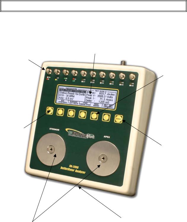
OVERVIEW
This section looks at the layout of a DA-2006 and gives descriptions of the elements that
|
|
|
are present. |
|
|
|
|
|
|||||
LCD Graphical Display: |
|
|
|
|
|||||||||
|
|
|
|
|
|
|
|
|
|
|
|
|
|
|
|
|
|
|
|
|
|
|
Shows Parameters for Test |
|
|
|
|
|
|
|
|
|
|
|
|
|
Data and Waveforms |
|
|
|
|
|
|
|
10 Universal |
|
|
|
|
|
|||||
|
|
|
|
|
|
|
|
|
|||||
|
|
|
Patient Lead |
|
|
|
|
5 Light Touch Keys |
|||||
|
|||||||||||||
|
|
|
Connectors: |
|
|
|
|
|
|
for Dynamic |
|||
|
|
|
RA |
R |
|
|
|
|
functions: |
||||
|
|
|
LA |
L |
|
|
|
|
These keys are |
||||
|
|
|
RL(-) |
N |
|
|
|
|
labeled in the |
||||
|
|
|
LL |
F |
|
|
|
|
bottom portion of |
||||
|
|
|
V1 |
C1 |
|
|
|
|
the screen and |
||||
|
|
|
V2 |
C2 |
|
|
|
|
change function |
||||
|
|
|
V3 |
C3 |
|
|
|
|
based on operating |
||||
|
|
|
V4 |
C4 |
|
|
|
|
mode. |
||||
|
|
|
V5 |
C5 |
|
|
|
|
|
|
|||
|
|
|
V6 |
C6 |
|
|
|
|
|
|
|||
|
|
|
|
|
|
|
|
|
|
|
|
|
|
|
|
|
|
|
|
|
|
|
|||||
|
Back Light Key |
|
|
|
|
|
|
|
|||||
|
for turning on |
|
|
|
|
|
|
|
|
||||
|
and off the |
|
|
|
|
|
|
||||||
|
backlight |
|
|
|
|
|
|
|
|
|
|
||
|
|
|
|
|
|
|
|
|
|
|
|
Range Key |
|
|
|
|
|
|
|
|
|
|
|
|
|
|
|
|
|
|
|
|
|
|
|
|
|
|
|
for selecting |
|
|
|
|
|
|
|
|
|
|
|
|
|
Defib input |
|
|
|
|
|
|
|
|
|
|
|
|
|
range high or |
|
|
|
|
|
|
|
|
|
|
|
|
|
low |
|
|
|
9V Battery |
Large Defib Plates: |
|
Compartment |
Fixed 50 ohm input |
|
(Rear) |
load for Defibrillator |
|
|
|
|
|
testing |
|
|
|
|
|
15

DA-2006 Series
This section looks at the layout of a DA-2006P and gives descriptions of the elements that
are present.
10 Universal Patient Lead Connectors: RA R
LA L
RL(-) N
LL F
V1 C1
V2 C2
V3 C3
V4 C4
V5 C5
V6 C6
Back Light Key for turning on and off the backlight
Pacemaker Input Jacks Variable Load (optional): 50-2300 ohms
Large Defib Plates: Fixed 50 ohm input load for Defibrillator testing
LCD Graphical Display: Shows Parameters for Test Data and Waveforms
5 Light Touch Keys for Dynamic functions:
These keys are labeled in the bottom portion of the screen and change function based on operating mode.
Range Key for selecting Defib input range high or low and pace mode
9V Battery
Compartment
(Rear)
Pacer Input Jacks Fixed Load:
50 ohm
16
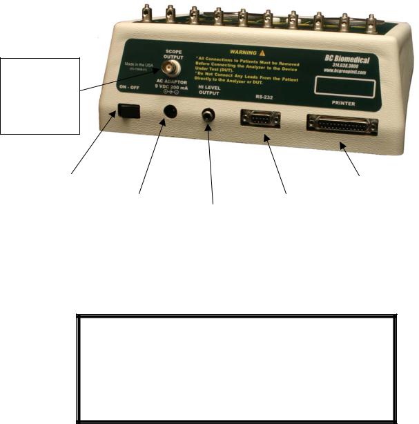
Overview
This section looks at the layout of the back and gives descriptions of the elements that are
present.
Oscilloscope output
BNC connector for easy viewing of input waveforms
|
Power Switch |
|
|
|
|
|
|
|
|
|
|
|
|
|
|
|
|
|
|
Parallel Port |
|
|
|
|
|
|
|
|
|
|||
|
|
|
|
|
|
|
|
|
|
Female 25-Pin |
|
|
|
|
AC Adaptor/ |
|
|
|
Serial Port |
|
D-Sub |
|
|
|
|
Battery |
|
High Level |
|
Female 9-Pin |
|
|
|
|
|
|
|
|
|
Connector |
|||
|
|
|
|
Eliminator |
|
ECG output |
|
D-Sub |
|
|
|
|
|
|
|
|
|
|
|||
|
|
|
|
2.1 mm Micro |
|
RCA Jack |
|
Connector |
|
|
|
|
|
|
Jack |
|
|
|
|
|
|
|
|
|
|
|
|
|
|
|
|
|
|
|
|
|
|
|
|
|
|
|
|
NOTE
The DA-2006 and the DA-2006P offer the same features, with the DA-2006P having the addition of a Transcutaneous Pacemaker Analyzer function (See Pacemaker Analyzer section
for more details).
17
DA-2006 Series
General Operation
The unit is controlled by 7 light touch keys. They allow the user to move around within the displayed parameters, select the desired options, choose a specific category and control the setup for the unit. When a key is depressed there is an audio click when it is accepted, or a razz tone if the key is invalid.
A large LCD graphics display with backlight provides the user with information about the current status of the device configuration options, test results and more. The display identifies the function of each key on a dynamic basis. As the operation mode changes, the key functions change to suit the operating mode.
Range Key
The  key scrolls through the ranges of the DA-2006 Series analyzers. Depressing the key will allow the user to select between High Defibrillator Range (1000J max), Low
Defibrillator Range (50J max) and, with the DA-2006P, Pacemaker Range. The default mode on power up is High Defibrillator Range.
Backlight Key
The Graphic LCD display may be viewed with or without the backlight. Depressing any key will activate the backlight. However, since the backlight will drain the battery if left on, it will automatically shut off after a user programmable delay when running on battery power.
The  key is provided to toggle the backlight on or off at any time.
18
Overview
Function Keys
There are five  keys that are used to provide general operational control. The functions of the keys vary depending on the current screen. The section of the screen just above the key indicates its current meaning.
NOTE: Only functions that are available to the user will be visible at any given time.
Sample Function Key Labeling
ECG Waveforms
The microprocessor has stored in its memory all of the digitalized waveforms. It sends the waveforms to a D/A converter, which generates an accurate analog representation. The waveform is then sent through resistor networks, developing the appropriate signals on the output terminals.
19
DA-2006 Series
Universal Patient Lead Connectors
The 10 Universal Patient Lead Connectors allow for 12 lead ECG simulations. AHA and
IEC color-coded labels are located on the face of the unit to aid in connecting the corresponding U.S. and International Patient Leads.
|
AHA Label |
IEC Label |
Description |
|
RA |
R |
Right Arm |
|
|
|
|
|
LA |
L |
Left Arm |
|
|
|
|
|
RL |
N |
Right Leg |
|
(reference or ground) |
||
|
|
|
|
|
LL |
F |
Left Leg |
|
|
|
|
|
V1 |
C1 |
V Leads (V1-V6) |
|
(U.S. and Canada) |
||
|
V2 |
C2 |
|
|
also referred to as pericardial, |
||
|
V3 |
C3 |
precordial or unipolar chest leads |
|
V4 |
C4 |
|
|
V5 |
C5 |
Chest Leads (C1-C6) |
|
V6 |
C6 |
|
|
(International) |
||
|
|
|
|
|
|
|
|
20
Overview
High Level Output (+)
A high level ECG output signal (200 X Amplitude Setting) is available on the RCA jack located on the rear of the unit.
Serial Port
A female 9-pin D-Sub connector is provided for the connection of the unit to a PC or laptop serial port (e.g. Com 1). This link is then used for either remote control or flash downloading of software upgrades.
Parallel Port
A female 25-pin D-Sub connector is provided for the connection of a printer via a Centronics parallel interface.
Oscilloscope Output
A BNC connector is provided to connect an oscilloscope to the unit. This output is a 200:1 attenuated version of the input to the Defibrillator Plates.
21
DA-2006 Series
Power Switch
A rocker switch is provided on the rear of the unit to turn the power on and off.
Power Supply
The unit utilizes two 9 Volt Alkaline Batteries in the bottom battery compartments. When the unit detects a LOW BATTERY condition (10% Battery Life), a warning window will appear once per minute to alert the user.
Battery Eliminator
The unit has a 2.1 mm micro jack for connecting a 10-Volt AC battery eliminator. The adapter will power the unit, but will not charge the battery.
22
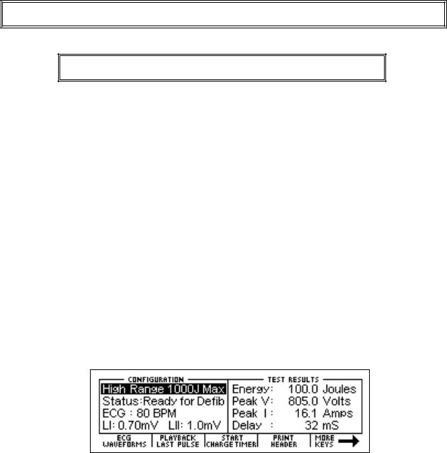
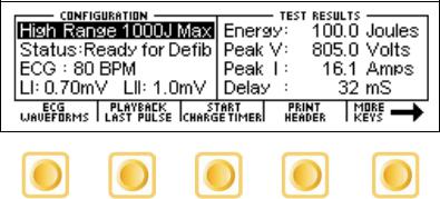
DEFIBRILLATOR ANALYZER
MAIN SCREEN
When the DA-2006 is first powered up, the Defibrillator Analyzer MAIN SCREEN will be displayed. This screen shows the current CONFIGURATION, the TEST RESULTS and the available FUNCTION KEYS. All defibrillator tests are run from the MAIN SCREEN. When the unit detects an input of greater than 100 Volts on the Defibrillator Plates (20 Volts in
Low Range), it will automatically begin a test.
The default configuration is the High Range Defibrillator mode. This mode allows for a waveform of up to 1000 Joules to be analyzed.
The following is a sample screen for this mode:
23
 Loading...