

Page 1
ELECTRICAL
SAFETY ANALYZER
WITH PATIENT SIMULATOR
SA-2010S
USER MANUAL
Page 2

Page 3

BC BIOMEDICAL
SA-2010S
TABLE OF CONTENTS
WARNINGS ................................................................................................................. 3
DESCRIPTION............................................................................................................. 4
LAYOUTS .................................................................................................................... 6
TESTING...................................................................................................................... 10
TEST MATRIX ................................................................................................... 17
ECG WAVEFORMS..................................................................................................... 18
MANUAL REVISIONS.................................................................................................. 19
WARRANTY................................................................................................................. 19
SPECIFICATIONS ....................................................................................................... 20
APPENDIX A -- LABEL .............................................................................................. 22
NOTES......................................................................................................................... 23
1
Page 4
NOTICE
BC GROUP INTERNATIONAL, INC. RESERVES THE RIGHT TO
MAKE CHANGES TO ITS PRODUCTS OR SPECIFICATIONS AT
ANY TIME, WITHOUT NOTICE, IN ORDER TO IMPROVE THE
DESIGN OR PERFORMANCE AND TO SUPPLY THE BEST
POSSIBLE PRODUCT. THE INFORMATION IN THIS MANUAL
HAS BEEN CAREFULLY CHECKED AND IS BELIEVED TO BE
ACCURATE. HOWEVER, NO RESPONSIBILITY IS ASSUMED
FOR INACCURACIES.
CONTACT INFORMATION
BC BIOMEDICAL
BC GROUP INTERNATIONAL, INC.
PO BOX 25125
9415 GENTRY AVE
ST. LOUIS, MO 63125
USA
1-800-242-8428
314-638-3800
www.bcgroupintl.com
sales@bcgroupintl.com
2
Page 5

Manual SA-2010S Copyright © 2006
www.bcgroupintl.com Made in the USA
7/06 Rev 03
All connections to patients must be removed
before connecting the Device Under Test (DUT)
to the Analyzer. A serious hazard may occur if
the patient is connected when testing
Do not connect any leads from the patient
directly to the Analyzer or DUT.
The Analyzer applies 120 or 240 VAC plus 10% to
the Patient leads or External test leads during
the Isolation test. Although this is current
limited by a 121K ohm internal resistor, per
standard test specifications, care should be
taken to prevent contact with this voltage.
Do not touch the test leads, connections or DUT
while depressing the Isolation Test key.
The Analyzer is not a continuous duty device.
Do not leave the device under test (DUT)
connected to this unit for extended periods. It is
intended for short duration testing within the
current limits and duty cycles specified.
WARNING
with the Analyzer.
WARNING
CAUTION
3
Page 6

BC BIOMEDICAL
SA-2010S
ELECTRICAL SAFETY ANALYZER
WITH PATIENT SIMULATOR
The Model SA-2010S is a Microprocessor based Electrical Safety Analyzer with a built in
Patient Simulator. It allows for a multitude of tests to be performed on a device using the
same unit and lead connections. It provides a full Electrical Safety Analyzer, as well as,
ECG Simulation with four waveforms with constant QRS duration and six machine
performance testing waveforms. There is Patient Lead testing for 10 inputs. The following
are highlights of some of the main features:
• LED STATUS INDICATORS
• AUDIO FEEDBACK
• TOUCH CONTROL KEYS – NO KNOBS
• 10 UNIVERSAL PATIENT LEAD INPUTS
• HIGH IMPACT PLASTIC CASE
SAFETY ANALYZER:
• LINE VOLTAGE MEASUREMENT
• DEVICE UNDER TEST CURRENT MEASUREMENT
• EARTH / GROUND LEAD RESISTANCE
• EARTH / GROUND LEAKAGE CURRENT
• ENCLOSURE / CHASSIS LEAKAGE CURRENT
• EXTERNAL RESISTANCE
• EXTERNAL LEAKAGE CURRENT
• SOURCE RECEPTACLE WIRING INTEGRITY MONITOR
• TRUE RMS MEASUREMENTS
• AAMI ES1-1993 or IEC 601 SELECTABLE TEST LOADS
• 85 TO 265 VAC OPERATION
• FULL 20 AMP RATING
• SELF TEST POINTS
• EXTERNALLY REPLACEABLE GROUND FUSE
• AUTOMATIC LOAD REVERSAL DELAY
• PATIENT LEAD TO LEAD LEAKAGE CURRENT
• PATIENT LEAD TO EARTH / GROUND LEAKAGE CURRENT
• PATIENT ISOLATION LEAKAGE CURRENT
• EXTERNAL ISOLATION LEAKAGE CURRENT
4
Page 7

PATIENT SIMULATOR:
• ECG: 30, 60, 120 AND 240 BPM
• SINE: 10, 60 AND 100 HZ
• SQUARE: 0.125 AND 2.0 HZ
• TRIANGLE: 2 HZ
• HIGH LEVEL OUTPUT (1 V p-p)
• AMPLITUDE ACCURACY: +/- 2%
• FREQUENCY ACCURACY: +/- 0.5%
5
Page 8
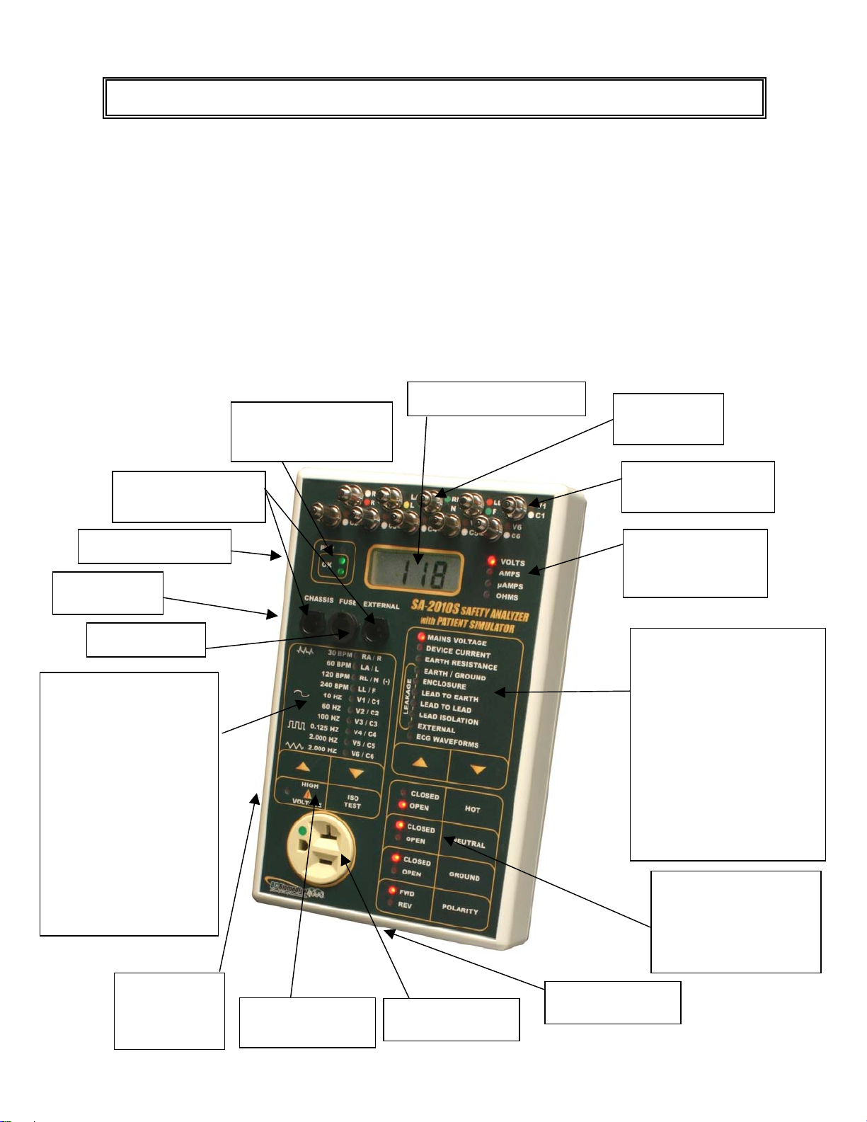
LAYOUT
p
A
p
A
This section looks at the layout of a SA-2010S and gives descriptions of the elements that
are present.
The unit is controlled by 9 light touch keys. They allow the user to perform all the functions
available in the system. There is an audio click when a key is depressed. Note that some
keys are locked out based on the current function setting. If an invalid key is depressed, a
Razz tone is sounded.
There are 33 LEDs and 3 Neon indicators to provide the user with full information about the
test that is being performed and the current setup. This section will review the layout and
operation of each of the elements.
Chassis and
External Connectors
High Level (+) Snap
Test Point
Sna
s
Fuse Access
ECG waveform and
Patient Lead Input
indicators with two light
touch arrow keys for
selection:
ECG— 30 BPM RA/A
60 BPM LA/L
120 BPM RL/N
240 BPM LL/F
Sine— 10 HZ V1/C1
60 HZ V2/C2
100 HZ V3/C3
Sq—0.125 HZ V4/C4
2 HZ V5/C5
Tri— 2 HZ V6/C6
3 Neon indicators for
Power Receptacle
Confirmation
3 1/2 digit LCD Display
High Level (-)
RL/N Snap
10 Universal
Patient Lead Inputs
Unit indicators:
Volts, Amps,
µAmps, Ohms
Function indicators with two
light touch arrow keys for
selection:
Mains Voltage,
Device Under Test Current,
Earth Resistance,
Earth/Ground Leakage,
Enclosure Leakage,
Lead to Earth Leakage,
Lead to Lead Leakage,
Lead Isolation Leakage,
External Leakage
ECG Waveforms
nalyzer Test
Receptacle Control
indicators and keys:
Hot, Neutral, Ground,
Polarity
Load
Selection
switch:
AMI, IEC
ISO Test indicator
and key
Receptacle for
DUT
ower cord
6
Power Cord for
unit
Page 9

Display
The main information in the system is presented in the 3½ digit LCD display. This data is
provided as simple meter readings with the units indicated by one of the four LEDs on the
right of the display. The units LEDs will automatically change to the necessary range
based on the function selected.
Universal Patient Lead Connectors
The 10 Universal Patent Lead Connectors allow for 12 lead ECG simulation with
independent outputs. AHA and IEC color-coded labels are located on the face of the unit to
aid in connecting the corresponding U.S. and International Patient Leads.
AHA Label IEC Label Description
RA R Right Arm
LA L Left Arm
RL N
Right Leg
(reference or ground)
LL F Left Leg
V Leads (V1-V6)
V1
V2
V3
V4
V5
V6
C1
C2
C3
C4
C5
C6
(U.S. and Canada)
also referred to as pericardial,
precordial or unipolar chest leads
Chest Leads (C1-C6)
(International)
Function Selection
Ten LEDs and two keys make up the Function Selection Section. The keys are up and
down arrows. When depressed, they step the Analyzer through the available options. The
LED next to the currently selected option is illuminated.
Load Selection
The unit may either use the AAMI ES1-1993 or IEC 601 Test load for measurements. This
is selected by the Load switch.
7
Page 10

Analyzer Test Receptacle Control
There are four keys and 8 LEDs in the Analyzer Test Receptacle Control Section. They
allow the manual control of the power connections that are made to the DUT. Internally, a
series of relays are switched by the microprocessor based on the keys that are depressed.
The LEDs indicate the current state of the power connections to the Receptacle.
Note: The Forward/Reverse keys have an internal switching delay feature that first turns off
the power to the DUT, delays for a short period, reverses the lines and the turns the unit
back on. This eliminates the need for the user to remember to delay at this point or risk
damage to the Analyzer.
Patient Lead Control
In the maximum configuration, there are ten patient lead inputs. During testing, it is
necessary to select between these leads, select all of them and apply High Voltage to
them. This section provides the control keys to do these test configurations and the LEDs
to indicate the current state.
There is one LED for each input. The markings on the right side of the LEDs are used
during these tests. Internally, there is a relay for each lead. The LEDs indicate when that
relay is on, thus selecting the indicated lead. The Up and Down arrow keys sequentially
select each lead in order and scroll through from None to 1-10 to All and around again.
To apply High Voltage to the leads, the Isolation Test key is depressed. It is only active in
the Isolation mode. It is a momentary key, the voltage is only applied while the key is held
down.
Waveform Selection
When the ECG Waveforms function is selected, the two keys and 10 LEDs become the
Waveform Selection Control Section. The markings o the left side of the LEDS are used
during these tests. The LEDs indicate which waveform is generated. The Up and Down
arrow keys sequentially select each waveform. Internally, the microprocessor has stored in
memory the digitalized waveforms. It sends the selected waveform to a D/A converter that
generates an accurate analog representation. This waveform is then sent through a
resistor network, developing the appropriate signals on the output terminals.
Power Outlet Indicators
These three Neon indicators help verify the polarity and wiring of the wall Receptacle that
the Safety Analyzer is plugged into.
8
Page 11

High Level Output (+)
A High Level snap is located on the side of the unit for connecting to the high level ECG
output signal (1 Volt p-p ). The connection is between High Level (+) and RL (-).
Connectors
There are two connectors for test cables on the unit. One is for the Chassis lead and the
other is for one of two different leads used for external testing. The test cables simply plug
into the sockets. There is a release pin on the cable plug that must be depressed to
remove the cable.
Fuse
There is a fuse in the ground leg of the Analyzer Test Receptacle. This is to help prevent
damage from excess ground current. It is located on the face for ease of replacement.
Test Receptacle
This receptacle is for the connection of the Device Under Test (DUT). It is Hospital Grade,
rated 20 A. An external patch cord is necessary to connect devices utilizing different types
of plugs.
Power Cord
The unit uses a standard Hospital Grade power cord. This cord provides power to both the
Safety Analyzer and the DUT. The connector is designed to plug into a 15A, 125 VAC,
Receptacle. For higher voltage and current applications, an external patch cord is required.
Self Test Points
There are two test points on the side of the unit that allow for a quick self test of the
Analyzer. They provide a fixed 1.0 Ohm resistance to Earth/Ground and a 100 µAmp
source to Earth/Ground.
9
Page 12

SAFETY ANALYZER TESTING
The SA-2000 Family of Safety Analyzers allows the user a great deal of flexibility in testing.
Any of the basic tests can be run and in almost any sequence. The information in this
section presents a systematic approach that is just one way to proceed. It is only
presented as a guide and it is the responsibility of the user to establish which tests are
required based on local codes, facilities practices and equipment manufacturer’s
recommendations.
The Analyzer requires a good Earth/Ground connection for operation. It should be plugged
into a “Hospital Grade” receptacle. This is necessary for both valid test results and
personal safety.
The unit will power up with the Neutral and Ground Closed, in Forward Polarity and with the
Hot Open. It is recommended that the unit be returned to this condition when plugging and
unplugging the Device Under Test (DUT).
Power Receptacle Confirmation
Once plugged in, the first step is to insure that the wall receptacle that the Safety Analyzer
is plugged into is wired properly (120 VAC Non-Isolated Power Systems Only). There are
three neon indicators in the unit that provide this confirmation. The REV indicator is red
and the other two are green. If the two green indicators are on, the Receptacle is wired
correctly. If not, utilize the following patterns to help determine the problem. Do not
proceed with any testing until you get the two green lights.
NOTE: Neutral/Ground Reversal is not checked.
All connections to patients must be removed
before connecting the Device Under Test (DUT)
to the Analyzer. A serious hazard may occur if
the patient is connected when testing
Do not connect any leads from the patient
directly to the Analyzer or DUT.
WARNING
with the Analyzer.
10
Page 13

Mains Voltage
With the Mains Voltage function selected, the display will show the Voltage that is present
on the incoming power lines. This is measured from Line to Neutral. Insure that this value
is within the specifications for the equipment that is to be tested. Also note that the voltage
may drop when the DUT is turned on. It is the value with the DUT powered that must be
within the DUT specification.
Device Current
With the Device Current function selected, the display will show the current draw of the
DUT. This is measured in hundredths of an Amp up to 19.99 Amps. The Receptacle
should be configure with Hot-Closed, Neutral-Closed, Ground-Closed and Polarity-Fwd, for
this measurement.
Earth Resistance
With the Earth Resistance function selected, the display will show the resistance between
the Chassis Test lead and the Earth/Ground Pin on the Analyzer Test Receptacle. This
resistance is a combination of the resistance within the DUT enclosure and the resistance
in the Earth/Ground Lead in the DUT power cord.
NOTE: This test has no meaning for equipment that does not use a three-wire
(Earth/Grounded) power cord.
The test requires that the Black (Kelvin) test cable be plugged into the Chassis Socket. The
other end should be connected to a solid ground point on the DUT. Consult the equipment
manufacturer’s documentation for the recommended connection point.
Since the Black (Kelvin) cable removes any error from the test lead and the internal
circuitry uses a similar connection at the Analyzer Test Receptacle ground pin (providing a
true 4 wire reading), the value displayed is the actual resistance of interest, without any
compensation. The display is in hundredths of Ohms and will read to 19.99 Ohms.
Overrange shows as 1_ _ _.
11
Page 14

Earth/Ground Leakage Current
With the Earth/Ground function selected and the Ground-Open, the display will show the
leakage current in the ground wire of the DUT. The display is in µAmps and will read from
0 to 1999.
Selecting this function automatically opens the connection to Earth/Ground and passes any
leakage current through a 1000 Ohms load with either AAMI ES1-1993 or IEC 601
frequency compensation as selected by the Load key.
The test should be performed for all receptacle switch combinations as called out in the
Test Matrix, or a subset of these based on the manufacturer’s specifications or local codes
and protocols.
NOTE: This test has no meaning for equipment that does not use a three-wire
(Earth/Grounded) power cord.
Enclosure Leakage
With the Enclosure function selected, the display will show the leakage current between the
Enclosure (Chassis) and Earth/Ground. The display is in µAmps and will read from 0 to
1999.
The test requires that the Black (Kelvin) test cable be plugged into the Chassis Socket. The
other end should be connected to a solid ground point on the DUT. Consult the equipment
manufacturer’s documentation for the recommended connection point.
NOTE: If a non-conductive enclosure is used, a 200 cm2 conductive foil pad should be
used. This foil is to be placed in close contact with the enclosure and connected to the
Black lead.
Any leakage current will flow through the Black lead and then through a 1000 Ohms load
with either AAMI ES1-1993 or IEC 601 frequency compensation as selected by the Load
key.
The test should be performed for all receptacle switch combinations as called out in the
Test Matrix, or a subset of these based on local codes, facilities practices and equipment
manufacturers recommendations.
12
Page 15

Lead to Earth/Ground Leakage
With the Lead to Earth/Ground function selected, the display will show the leakage current
between the selected Patient Lead and Earth/Ground. The display is in µAmps and will
read from 0 to 1999.
Attach the patient leads to the connectors on the top of the Safety Analyzer. The Up and
Down arrow keys may then be used to select any individual lead or all of the leads.
Internally, relays connect the leads as necessary. The LEDs indicate the selected lead(s).
The test should be performed for all receptacle switch combinations as called out in the
Test Matrix, or a subset of these based on local codes, facilities practices and equipment
manufacturer’s recommendations. This is to be done for each lead individually and all leads
together.
This test measures the leakage current that would flow through the leads if the patient were
to come into contact with Earth/Ground.
Lead to Lead Leakage
With the Lead to Lead function selected, the display will show the leakage current between
the selected Patient Lead and All other patient leads. The display is in µAmps and will read
from 0 to 1999.
Attach the patient leads to the connectors on the top of the Safety Analyzer. The Up and
Down arrow keys may then be used to select any individual lead. Internally, relays
connect the leads as necessary. The LEDs indicate the selected lead.
The test should be performed for all receptacle switch combinations as called out in the
Test Matrix, or a subset of these based on local codes, facilities practices and equipment
manufacturers recommendations. This is to be done for each lead individually.
This test measures the current that would flow from a lead to other leads. Normally these
are Auxiliary currents from bias, measurement and sensing circuits.
13
Page 16

Lead Isolation
With the Lead Isolation function selected and the Isolation Voltage key depressed, the
display will show the leakage current between the selected Patient Lead(s) and
Earth/Ground. The display is in µAmps and will read from 0 to 1999.
Attach the patient leads to the connectors on the top of the Safety Analyzer. The Up and
Down arrow keys may then be used to select any individual lead and all of the leads.
Internally, relays connect the leads as necessary. The LEDs indicate the selected lead(s).
As each lead and then All leads are selected, depress and hold the Isolation Voltage key.
This will apply 110% of the line voltage through a 121K resistor to the selected lead(s) and
measure the current that flows to Earth/Ground through a 1000 Ohms load with either
AAMI ES1-1993 or IEC 601 frequency compensation as selected by the Load key.
The test should be performed for all receptacle switch combinations as called out in the
Test Matrix, or a subset of these based on the manufacturer’s specifications or local codes
and protocols. This is to be done for each lead individually and All leads together.
This test measures the leakage current that would flow through the lead(s) if the patient
were to come into contact with Line voltage. This is referred to as MAP (MAINS on Applied
Parts).
The Analyzer applies 120 or 240 VAC plus 10% to
the Patient leads or External test leads during
the Isolation test. Although this is current
limited by a 121K Ohms internal resistor, per
standard test specifications, care should be
taken to prevent contact with this voltage.
Do not touch the test leads, connections or DUT
while depressing the Isolation Test key.
WARNING
14
Page 17

Point to Point Measurements
The unit has the ability to measure Leakage Current, Isolation Leakage Current and
Resistance between two points, utilizing two test leads. These tests are separated
because they use a slightly different setup than the previous tests.
Point to Point Leakage Current
With the External function selected, the display will show the leakage current between the
test leads. The display is in µAmps and will read from 0 to 1999.
The test requires that the Black test cable be plugged into the Chassis Socket and the Red
test cable be plugged into the External Socket. The other end of the leads are then
attached to the points of interest.
Any current flowing between the test points is passed through a 1000 Ohms load with either
AAMI ES1-1993 or IEC 601 frequency compensation as selected by the Load key.
Point to Point Isolation Leakage Current
With the External function selected and the Isolation Voltage key depressed, the display will
show the isolation leakage current between the test leads. The display is in µAmps and will
read from 0 to 1999.
The test requires that the Black test cable be plugged into the Chassis Socket and the Red
test cable be plugged into the External Socket. The other end of the leads are then
attached to the points of interest.
Depress and hold the Isolation Voltage key. This will apply 110% of the line voltage
through a 121K resistor to the test leads and measure the current that flows through a 1000
Ohms load with either AAMI ES1-1993 or IEC 601 frequency compensation as selected by
the Load key.
The Analyzer applies 120 or 240 VAC plus 10% to
the Patient leads or External test leads during
the Isolation test. Although this is current
limited by a 121K Ohms internal resistor, per
standard test specifications, care should be
taken to prevent contact with this voltage.
Do not touch the test leads, connections or DUT
while depressing the Isolation Test key.
WARNING
15
Page 18

Point to Point Resistance
With the Earth Resistance function selected, the display will show the resistance between
the two test leads. The display is in hundredths of Ohms and will read to 19.99 Ohms.
Remove any device plugged into the Analyzer Test Receptacle.
The test requires two Black (Kelvin) test cables--one in the Chassis Socket and the other in
the External Socket. The other ends should be connected to the points of interest.
Since the Black (Kelvin) cable removes any error from the test leads (providing a true 4
wire reading), the value displayed is the actual resistance of interest, without any
compensation.
NOTE: If there is a DC voltage present between the two test points, the reading may
contain an error. This can be checked by reversing the connections. If the readings differ,
average the two to get the actual resistance value.
16
Page 19

Test Matrix
DUT
POWER
GROUND POLARITY HOT NEUTRAL
On Closed Forward Closed Closed
On Closed Forward Closed Open
On Closed Forward Open Closed
On Closed Forward Open Open
On Closed Reverse Closed Closed
On Closed Reverse Closed Open
On Closed Reverse Open Closed
On Closed Reverse Open Open
On Open Forward Closed Closed
On Open Forward Closed Open
On Open Forward Open Closed
On Open Forward Open Open
On
On
On
Open Reverse Closed Closed
Open Reverse Closed Open
Open Reverse Open Closed
On
Open Reverse Open Open
Off Closed Forward Closed Closed
Off Closed Forward Closed Open
Off Closed Forward Open Closed
Off Closed Forward Open Open
Off Closed Reverse Closed Closed
Off Closed Reverse Closed Open
Off Closed Reverse Open Closed
Off Closed Reverse Open Open
Off Open Forward Closed Closed
Off Open Forward Closed Open
Off Open Forward Open Closed
Off Open Forward Open Open
Off Open Reverse Closed Closed
Off Open Reverse Closed Open
Off Open Reverse Open Closed
Off Open Reverse Open Open
17
Page 20

ECG WAVEFORMS
The SA-2010S provides ECG Waveforms to aid in the verification of the basic operational
characteristics of cardiac-monitoring equipment. The information in this section presents a
listing of available waveforms. It is the responsibility of the user to establish which
waveform verifications are required based on local codes, facilities practices and equipment
manufacturer’s recommendations.
Pulse Waves
The SA-2010S simulates a Normal Sinus Rhythm pulse at 30, 60, 120 and 240 BPM.
With ECG Waveforms function selected, use the arrow keys under the waveform LEDs to
select the desired pulse. The display is unused in this mode and will show over range. The
LEDs will pulse with the waveform.
Performance Waves
Sine
The SA-2010S sends out Sine waves of 10, 60 and 100 Hz. With ECG Waveforms function
selected, use the arrow keys under the waveform LEDs to select the desired Sine wave.
The display is unused in this mode and will show over range.
Square
The SA-2010S sends out Square waves of 0.125 and 2 Hz. With ECG Waveforms function
selected, use the arrow keys under the waveform LEDs to select the desired Square wave.
The display is unused in this mode and will show over range.
Triangle
The SA-2010S sends out Triangle waves of 2 Hz. With ECG Waveforms function selected,
use the arrow keys under the waveform LEDs to select the desired Triangle wave. The
display is unused in this mode and will show over range.
18
Page 21

MANUAL REVISIONS
A
A
Revision #
Rev 01 DT7338 Preliminary Manual
Rev 02 DT7338CC Photos Updated
WARRANTY
FROM DEFECTS IN MATERIALS AND WORKMANSHIP UNDER THE SERVICE FOR WHICH THEY
RE INTENDED. THIS WARRANTY IS EFFECTIVE FOR TWELVE MONTHS FROM THE DATE OF
SHIPMENT.
EXCLUSIONS: THIS WARRANTY IS IN LIEU OF ANY OTHER WARRANTY EXPRESSED OR
IMPLIED, INCLUDING, BUT NOT LIMITED TO ANY IMPLIED WARRANTY OF MERCHANTABILITY
OR FITNESS FOR A PARTICULAR PURPOSE.
BC GROUP INTERNATIONAL, INC. IS NOT LIABLE FOR ANY INCIDENTAL OR CONSEQUENTIAL
DAMAGES.
NO PERSON OTHER THAN AN OFFICER IS AUTHORIZED TO GIVE ANY OTHER WARRANTY OR
SSUME ANY LIABILITY.
REMEDIES: THE PURCHASER'S SOLE AND EXCLUSIVE REMEDY SHALL BE: (1) THE REPAIR OR
REPLACEMENT OF DEFECTIVE PARTS OR PRODUCTS, WITHOUT CHARGE. (2) AT THE OPTION
OF BC GROUP INTERNATIONAL, INC., THE REFUND OF THE PURCHASE PRICE.
P:\MANUALS\BCGroup\…\SA2010S_UM_Rev03.doc
Program # Revisions Made
LIMITED WARRANTY
: BC GROUP INTERNATIONAL, INC. WARRANTS ITS NEW PRODUCTS TO BE FREE
19
Page 22

SPECIFICATIONS
LINE VOLTAGE
DUT CURRENT
SCALES & RANGES
85 – 265 VAC, 50/60 Hz, RMS
+/- 3% of reading, +/- 1 digit
0 – 19.99 Amps, RMS
+/- 5% of reading, +/- 1 digit
EARTH/GROUND
RESISTANCE
LEAKAGE CURRENT 0-1999 µAmps, RMS
DC and 25 to 1KHz +/- 1.0% of reading, +/- 1 digit
+/- 1% of reading, +/- 1 digit
0-19.99 Ohms
1.00 KHz – 100 KHz +/- 2.5% of reading, +/- 1 digit
100 KHz – 1.00 MHz +/- 5.0% of reading, +/- 1 digit
ISOLATION TEST
LOAD
CAPACITY
110% Line Voltage
+/- 5%
AAMI ES1-1993 or IEC 601
(Selectable)
15 Amps, 30 Minutes
20 Amps, 5 Minutes
NORMAL SINUS
RHYTHM
RATE 30,60,120,240 BPM
PERFORMANCE
SINE WAVE 10,60,100 Hz
SQUARE WAVE 0.125, 2.000 Hz
TRIANGLE WAVE 2.000 Hz
20
Page 23

LEAD 1 1.75 mV
LEAD 2 2.75 mV
LEAD 3 1.00 mV
LEAD TO LEAD
IMPEDENCE
LEAD TEST
IMPEDENCE
OUTPUT
1000 Ohms
< 1000 Ohms
ACCURACY
AMPLITUDE +/- 2 % Lead II
FREQUENCY 0.5 %
PHYSICAL
ENCLOSURE
WEIGHT
DISPLAY .5 inch, 3 ½ digit LCD
FACE PLATE Lexan, Back printed
OPERATING RANGE 15 to 40 C
STORAGE RANGE -20 to 65 C
8.625 x 5.5 x 1.625 Inches
(219 x 140 x 41 mm)
ABS Plastic
<2.5 Lbs
(<1.1 Kg)
POWER
FUSE
ELECTRICAL
85 to 265 VAC, 50/60 Hz
5 VA
250 mA, 250 V
5X20 mm, Fast Acting
Receptacle Ground Leg
21
Page 24

APPENDIX A -- LABEL
The following is a representation of the label found on the back of the SA-2010S:
22
Page 25

NOTES
23
 Loading...