

Page 1
ECG
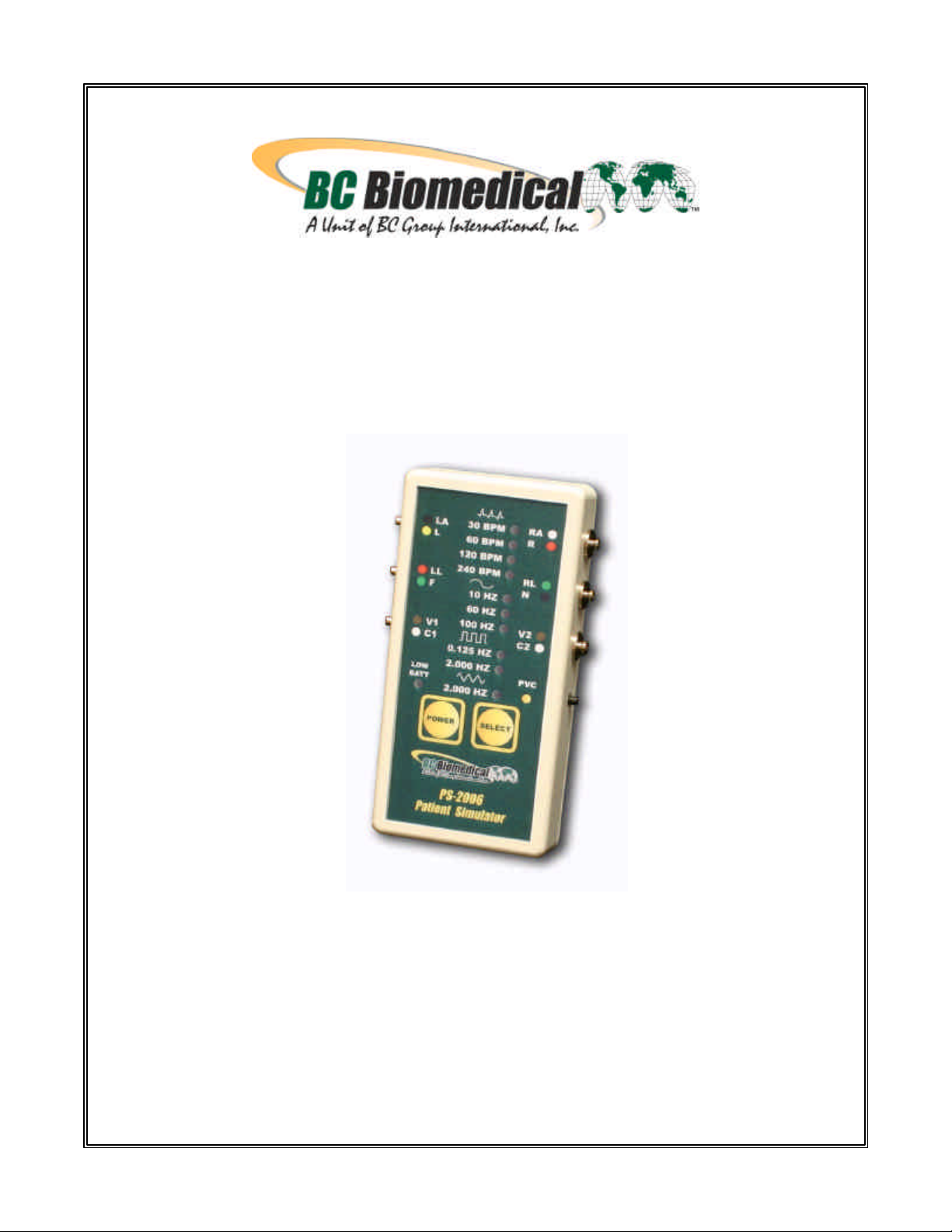
PATIENT SIMULATOR
PS-2006
USER MANUAL
Page 2

Page 3

BC BIOMEDICAL
PS-2006
TABLE OF CONTENTS
WARNINGS.................................................................................................................. 2
DESCRIPTION............................................................................................................. 3
LAYOUT....................................................................................................................... 4
MANUAL REVISIONS .................................................................................................. 7
WARRANTY................................................................................................................. 7
SPECIFICATIONS........................................................................................................ 8
NOTES........................................................................................................................ 10
iii N O T I C E iii
BC GROUP INTERNATIONAL, INC. RESERVES THE RIGHT TO MAKE
CHANGES TO ITS PRODUCTS OR SPECIFICATIONS AT ANY TIME,
WITHOUT NOTICE, IN ORDER TO IMPROVE THE DESIGN OR
PERFORMANCE AND TO SUPPLY THE BEST POSSIBLE PRODUCT.
THE INFORMATION IN THIS MANUAL HAS BEEN CAREFULLY CHECKED
AND IS BELIEVED TO BE ACCURATE. HOWEVER, NO RESPONSIBILITY IS
ASSUMED FOR INACCURACIES.
1
Page 4

before connecting the Device Under Test (DUT) to
Do not connect any leads from the patient directly
All connections to patients must be removed
the Simulator. A serious hazard may occur if the
patient is connected when testing
to the Simulator or DUT.
WARNING
with the Simulator.
Manual PS-2006 Copyright © 2006
05/06 Rev 02
Made in the USA
2
Page 5

BC GROUP
PS-2006
PATIENT SIMULATOR
The Model PS-2006 is a Microprocessor based Patient Simulator. It provides ECG
Simulation with four waveforms with constant QRS duration and six machine performance
testing waveforms. The following are highlights of some of the main features:
• 6 PATIENT LEAD SNAP CONNECTORS
• ECG: 30, 60, 120 AND 240 BPM
• PVC ARRHYTHMIA
• SINE: 10, 60 AND 100 HZ
• SQUARE: 0.125 AND 2.0 HZ
• TRIANGLE: 2 HZ
• AMPLITUDE ACCURACY: +/- 2%
• FREQUENCY ACCURACY: +/- 0.5% OF SETTING
• 9 VOLT BATTERY POWER
• LOW BATTERY INDICATOR
• % BATTERY LIFE INDICATOR
• HIGH IMPACT PLASTIC CASE
• LIGHT TOUCH KEYS
3
Page 6

Indicator LED
LAYOUT
This section looks at the layout of a PS-2006 and gives descriptions of the elements that
are present.
Patient Lead Snap
Connectors:
LA L
LL F
V1 C1
10 Waveforms
with LED
Indicators for
Selection:
ECG--30, 60,
120, 240 BPM
Sine--10, 60,
100 HZ
Square--0.125,
2.000 HZ
Triangle--2 HZ
Low Battery
9V Battery
Compartment
(Back)
The unit is controlled by 2 light touch keys. They allow the user to select waveforms and
control the power for the unit. There is a light touch push switch that allows the user to
trigger the PVC Arrhythmia.
There are 10 LEDs to provide the user with information about waveforms that are
generated and 1 LED for Low Battery Indication.
Patient Lead Snap
Connectors:
RA R
RL N
V2 C2
PVC Trigger
2 Light Touch
Keys for Power
and Waveform
Selection
4
Page 7

Patient Lead Snap Connectors
AHA and IEC color-coded labels are located on the face of the unit to aid in connecting the
corresponding U.S. and International Patient Leads.
AHA Label IEC Label Description
RA R Right Arm
LA L Left Arm
RL N
LL F Left Leg
V1
V2
C1
C2
Right Leg
(reference or ground)
V Leads (V1-V2)
(U.S. and Canada)
also referred to as pericardial,
precordial or unipolar chest leads
Chest Leads (C1-C2)
(International)
Waveform Selection
There is one key and 10 LEDs in the Waveform Selection Control Section. The LEDs
indicate which waveform is generated. The SELECT key sequentially selects each
waveform. Internally, the microprocessor has stored in memory the digitalized waveforms.
It sends the selected waveform to a D/A converter that generates an accurate analog
representation. This waveform is then sent through a resistor network, developing the
appropriate signals on the output terminals.
PVC Trigger
A switch is used to manually trigger PVC Arrhythmias. When the output is set to Normal
Sinus Rhythm, the PVC switch will cause the next NSR output to be replaced by a PVC
waveform. PVC triggers will be accumulated and the PVC waveform will be output until all
PVCs have been run.
5
Page 8

Power Key
The POWER key toggles the unit on and off.
Auto Power Off
The unit will automatically turn off after 10 minutes of no key activity to conserve the
battery.
To override this feature and keep the unit on continuously, press and hold the SELECT
key while turning the unit on. This will keep the unit on until it is manually turned off. The
“Low Batt” LED will illuminate for 3 sec to indicate that the Auto Power Off feature has
been turned off.
Power Supply
The unit utilizes a 9 Volt Alkaline Battery in the rear battery compartment. When the unit
detects a LOW BATTERY, the LED in the lower left of the face will blink, indicating the
need to change the battery.
Percent of Battery Life Indicator
The unit provides an indication of the Percent of battery life left on the 9 Volt Alkaline
Battery. An A/D converter monitors the battery voltage. Continuously holding down the
SELECT key will change the 10 waveform LEDs into a Percent of Battery Life display, with
each LED representing 10%. The stack will strobe up to the present level and flash. This
sequence will continue while the SELECT key is depressed.
6
Page 9

WARRANTS ITS NEW PRODUCTS TO BE FREE
FROM DEFECTS IN MATERIALS AND WORKMANSHIP UNDER THE SERVICE FOR WHICH THEY ARE
INTENDED. THIS WARRANTY IS EFFECTIVE FOR TWELVE MONTHS FROM THE DATE OF
ANY OTHER WARRANTY EXPRESSED OR IMPLIED,
OR FITNESS
IS NOT LIABLE FOR ANY INCIDENTAL OR CONSEQUENTIAL
HER THAN AN OFFICER IS AUTHORIZED TO GIVE ANY OTHER WARRANTY OR
THE PURCHASER'S SOLE AND EXCLUSIVE REMEDY SHALL BE: (1) THE REPAIR OR
REPLACEMENT OF DEFECTIVE PARTS OR PRODUCTS, WITHOUT CHARGE. (2) AT THE OPTION
MANUAL REVISIONS
Revision # Program # Revisions Made
Rev 01 DT7344-2 Preliminary Manual
Rev 02 DT73446CA Pictures Updated
WARRANTY: BC GROUP INTERNATIONAL, INC.
SHIPMENT.
EXCLUSIONS: THIS WARRANTY IS IN LIEU OF
INCLUDING, BUT NOT LIMITED TO ANY IMPLIED WARRANTY OF MERCHANTABILITY
FOR A PARTICULAR PURPOSE.
BC GROUP INTERNATIONAL, INC.
DAMAGES.
NO PERSON OT
ASSUME ANY LIABILITY.
REMEDIES:
OF BC GROUP INTERNATIONAL, INC., THE REFUND OF THE PURCHASE PRICE.
P:\MANUALS\BCGroup\Published Versions\Ps2000\PS2006_UM_Rev02.doc
LIMITED WARRANTY
7
Page 10

SPECIFICATIONS
Normal Sinus Rhythm
Rate 30,60,120,240 BPM
Performance
Sine Wave 10,60,100 Hz
Square Wave 0.125, 2.000 Hz
Triangle Wave 2.000 Hz
SCALES & RANGES
LEAD 1 1.75 mV
LEAD 2 2.75 mV
LEAD 3 1.00 mV
LEAD TO LEAD
IMPEDENCE
LEAD TEST
IMPEDENCE
OUTPUT
AMPLITUDE +/- 2 % Lead II
FREQUENCY 0.5 %
ACCURACY
1000 Ohms
< 1000 Ohms
8
Page 11

ENCLOSURE
WEIGHT
FACE PLATE Lexan, Back printed
OPERATING RANGE 15 to 40 degrees C
STORAGE RANGE -20 to 65 degrees C
PHYSICAL
5.12 x 2.56 x 0.97 Inches
(130 x 65 x 25 mm)
ABS Plastic
> ½ Lb
(> 0.23 Kg)
ELECTRICAL
POWER
Battery, 9 VDC
(NEDA 1604)
Alkaline
9
Page 12

NOTES
10
 Loading...