

Page 1

IPA-2000S
Infusion Pump Analyzer
with Safety Analyzer
IPA-2000
Infusion Pump Analyzer
User Manual
Manual 2000S01
Copyright © 2002
Revision 8
October 2003
i
Page 2

INTRINTR
INTR
INTRINTR
NOTICES
LIMITED WARRANTY
WARRANTY: BC Biomedical warrants its new products to be free from defects in
materials and workmanship under the service for which they are intended. This warranty
is effective for twelve months from the date of shipment.
EXCLUSIONS: This warranty is in lieu of any other warranty, expressed or implied;
including, but not limited to, any implied warranty of merchantability or fitness for a
particular purpose.
BC Biomedical is not liable for any incidental or consequential damages.
No person other than an officer is authorized to give any other warranty or assume any
liability.
ODUCTIONODUCTION
ODUCTION
ODUCTIONODUCTION
REMEDIES: The purchaser’s sole and exclusive remedy shall be:
(1) The repair or replacement of defective parts or products.
(2) At the discretion of BC Biomedical, the refund of the purchase price.
Specifications and information contained in this document are for informational use
only and are subject to change without notice. This material should in no way be
construed as a commitment by BC Biomedical. It has been checked carefully and is
believed to be correct. However, no responsibility or liability for any errors or
inaccuracies is assumed by BC Biomedical.
The unit covered by this manual is for routine maintenance only. It is not to be used for
calibration.
ii
NOTICES
Page 3

INTRODUCTIONINTRODUCTION
INTRODUCTION
INTRODUCTIONINTRODUCTION
PRODUCTS COVERED BY MANUAL
This manual gives a comprehensive overview of all the available features for the IPA2000 Series of products. Some of the sections and information are not applicable to
every product.
IPA-2000S: This product includes the Infusion Pump Analyzer and the Safety Analyzer.
All portions of this manual are applicable.
IPA-2000: This product includes only the Infusion Pump Analyzer. The portions of this
manual referring to the Safety Analyzer are not applicable.
DOCUMENT REVISION RECORD:
REVISION DATE PROGRAM VERSION CHANGES
1 7/02 DT7310CB 1.2 Beta Version Release
2 10/02 DT7310CD (2000S) 1.4 (2000S) Specifications Updated
DT7315CA (2000) 1.1 (2000) 2000 References
3 1/03 DT7310CF (2000S) 1.6 (2000S) Specifications Updated
DT7315CC(2000) 1.3 (2000) Editing Updates
4 4/03 DT7310CG(2000S) 1.7(2000S) Priming, Purging and
DT7315CD(2000) 1.4(2000) Editing Updates
5 5/03 DT7310CH(2000S) 1.8(2000S) Editing
DT7315CE(2000) 1.5(2000) Updates
6 6/03 DT7310CI(2000S) 1.9(2000S) Alarm List Adjusted
DT7315CF(2000) 1.6(2000)
7 7/03 DT7310CJ(2000S) 1.10(2000S) Specifications Updated
DT7310CF(2000) 1.6(2000)
8 10/03 DT7310CK(2000S) 1.11(2000S) Line Voltage, Baud
DT7310CF(2000) 1.6(2000) Rate and Alarm Scan
P:\Manuals\BCGroup\---\7310_rev08_---.pmd
iii
NOTICES
Page 4

TABLE OF CONTENTS
INTRINTR
INTR
INTRINTR
ODUCTIONODUCTION
ODUCTION
ODUCTIONODUCTION
Part 1 About the IPA-2000 Series A general overview of the System....................
Infusion Pump Analyzer Overview.....................
Safety Analyzer Overview.....................................
Instrument Overview
Instrument Physical Overview..............................
Unit Front
Unit Front
Unit Back
Module
Module Back
Commercial and Main Screen
Connections
Connections Overview
-
Panel...................................................
-
Panel Controls....................................
-
Panel...................................................
Front-Panel.............................................
-
Panel..............................................
.
............................
.
........................................
1-1
1-3
1-4
1-5
1-6
1-7
1-9
1-10
1-11
1-12
1-13
iv
Module Connection
Printer Connection
Keyboard Connection
Computer Connection..........................................
Infusion Pump Analyzer
Safety Analyzer
Specifications
.
.............................................
.
..............................................
.
..........................................
/
DUT Connection.........
/
DUT Connection......................
.
...........................................................
TABLE OF CONTENTS
1-14
1-15
1-16
1-17
1-18
1-20
1-21
Page 5

INTRINTR
INTR
INTRINTR
ODUCTIONODUCTION
ODUCTION
ODUCTIONODUCTION
Part 2 General Operations A step by step walk through of the operations...........
that support the running and processing of
the tests.
Administration Setup
Administration Setup Overview
Administration Setup
User Setup
User Setup Overview
User Setup
Model Selection
Model Selection Overview
Model Selection...................................................
Priming
Priming Overview ................................................
...........................................
..........................................
..........................................................
...........................
...................................
2-1
2-2
2-3
2-9
2-10
2-16
2-18
2-23
Priming ...............
Purging
Purging Overview
Purging
Datalog
Datalog Overview
Printing Reports
Printing Reports Overview
Automatically Printing Reports............................
Manually Printing Reports Overview....................
Manually Printing Reports....................................
................................................................
................................................
................................................
................................................
..................................
2-25
2-28
2-29
2-31
2-33
2-34
2-35
2-36
v
TABLE OF CONTENTS
Page 6

INTRINTR
INTR
INTRINTR
ODUCTIONODUCTION
ODUCTION
ODUCTIONODUCTION
System Memory Overview ...................................
Alarm Overview
Flash
Flash Overview
Flashing Files
.......................................................
.
..................................................
.
.....................................................
2-38
2-39
2-42
2-44
vi
TABLE OF CONTENTS
Page 7

INTRODUCTIONINTRODUCTION
INTRODUCTION
INTRODUCTIONINTRODUCTION
Part 3 Infusion Analyzer--Flow Mode A step by step walk through of ................
running an Infusion Analyzer
Flow or Flow--PCA test.
Infusion Analyzer--Flow
Flow Test Overview
Getting Ready for a Flow Test.............................
Running a Flow Test............................................
Datalog Sample for Flow Test.............................
Infusion Analyzer--Flow--PCA
Flow--PCA Test Overview
Getting Ready for a Flow--PCA Test
Running a Flow--PCA Test..................................
Datalog Sample for Flow--PCA Test
Datalog--Flow Test
.............................................
...................................
...................
..................
3-1
3-2
3-4
3-6
3-8
3-9
3-11
3-13
3-16
Flow Test Datalog Overview................................
Flow Test Datalog................................................
3-17
3-18
vii
TABLE OF CONTENTS
Page 8

INTRODUCTIONINTRODUCTION
INTRODUCTION
INTRODUCTIONINTRODUCTION
Part 4 Infusion Analyzer--Occlusion Mode A step by step walk through..........
of running a Distal or Proximal
Occlusion test.
Infusion Analyzer--Distal Occlusion
Distal Occlusion Test Overview
Getting Ready for a Distal Occlusion Test
Running a Distal Occlusion Test.........................
Datalog Sample for a Distal Occlusion Test
Infusion Analyzer--Proximal Occlusion
Proximal Occlusion Test Overview
Getting Ready for a Proximal Occlusion Test
Running a Proximal Occlusion Test....................
Datalog--Occlusion
Occlusion Test Datalog Overview .......................
..........................
..........
.......
.....................
.....
4-1
4-2
4-4
4-6
4-8
4-9
4-10
4-11
4-12
Occlusion Test Datalog.......................................
4-13
viii
TABLE OF CONTENTS
Page 9

INTRINTR
INTR
INTRINTR
ODUCTIONODUCTION
ODUCTION
ODUCTIONODUCTION
Part 5 Safety Analyzer--Manual Mode A step by step walk through of ...............
running a Manual Safety
Analyzer test.
Safety Analyzer--Manual Mode
Manual Test Overview
Getting Ready for a Manual Test
Running a Manual Test........................................
.........................................
.........................
Part 6 Safety Analyzer--Automatic Mode A step by step walk through ............
of running an Automatic Safety
Analyzer test.
Safety Analyzer--Automatic Mode
Automatic Test Overview.........................
Getting Ready for an Automatic Test.......
5-1
5-2
5-3
5-4
6-1
6-2
6-3
Running an Automatic Test .....................
Datalog Sample for an Automatic Test....
Datalog--Safety Analyzer
Safety Analyzer Datalog Overview ......................
Safety Analyzer Datalog......................................
6-4
6-15
6-16
6-17
ix
TABLE OF CONTENTS
Page 10

This Page Intentionally Left Blank.
x
Page 11
ABOUT ABOUT
ABOUT
ABOUT ABOUT
PART 1 : ABOUT THE IPA-2000 Series
THE IPTHE IP
THE IP
THE IPTHE IP
A-2000 SERIESA-2000 SERIES
A-2000 SERIES
A-2000 SERIESA-2000 SERIES
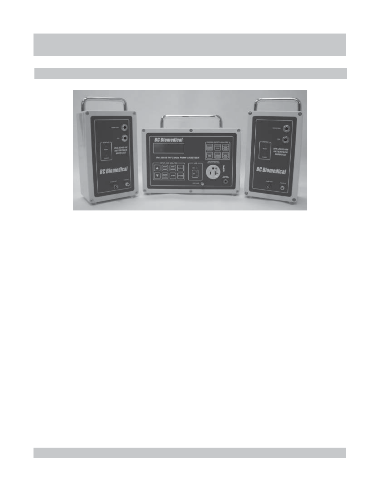
The IPA-2000S is an Infusion Pump Analyzer that can perform
Flow, Flow--PCA, Distal Occlusion and Proximal Occlusion
tests. Also included is a built-in Safety Analyzer that can be
run manually or automatically, greatly simplifying the testing
process.
There can be up to two Infusion Pump test modules connected
to the main unit. These Interface Modules are totally
interchangeable and may plug into either of the two inputs. The
unit automatically senses the interface modules and their
locations. It will then configure the system accordingly.
There are provisions for a keyboard, a printer and a serial
communications cable on the back of the unit. These allow for
1-1
keyboard data entry, printing of reports, downloading of data
and uploading of programs.
PART 1 : ABOUT THE IPA-2000 SERIES
Page 12
ABOUT ABOUT
ABOUT
ABOUT ABOUT
THE IPTHE IP
THE IP
THE IPTHE IP
A-2000 SERIESA-2000 SERIES
A-2000 SERIES
A-2000 SERIESA-2000 SERIES
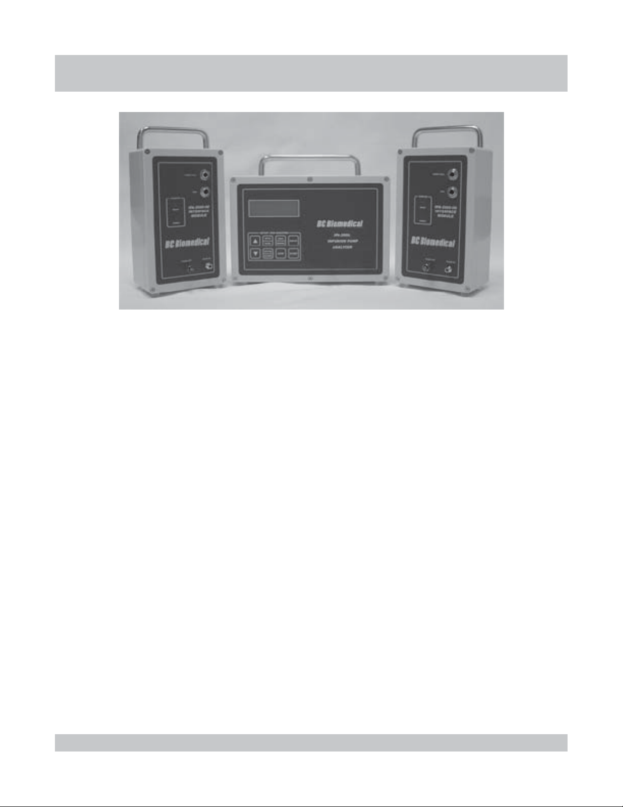
The IPA-2000 is an Infusion Pump Analyzer that can perform
Flow, Flow--PCA, Distal Occlusion and Proximal Occlusion
tests. Portions of this manual dealing with the Safety Analyzer
are not applicable to this unit.
There can be up to two Infusion Pump test modules connected
to the main unit. These Interface Modules are totally
interchangeable and may plug into either of the two inputs. The
unit automatically senses the interface modules and their
locations. It will then configure the system accordingly.
There are provisions for a keyboard, a printer and a serial
communications cable on the back of the unit. These allow for
keyboard data entry, printing of reports, downloading of data
and uploading of programs.
1-2
PART 1 : ABOUT THE IPA-2000 SERIES
Page 13

INFUSION PUMP INFUSION PUMP
INFUSION PUMP
INFUSION PUMP INFUSION PUMP
INFUSION PUMP ANALYZER OVERVIEW
ANAN
AN
ANAN
ALAL
YZER OYZER O
AL
YZER O
ALAL
YZER OYZER O
VERVER
VER
VERVER
The Infusion Pump Analyzer is used to monitor the flow and
pressure of the fluid moving through a pump. There are four
tests within the Infusion Pump Analyzer: Flow, Flow--PCA, Distal
Occlusion and Proximal Occlusion. Fully configured with two
interface modules, the system can run two independent
channels, with any combination of tests active.
The Flow test records elapsed time, average flow, instantaneous
flow, volume and pressure at data points and reports the average
VIEWVIEW
VIEW
VIEWVIEW
flow, total volume, elapsed time and back pressure at the
conclusion of the test. The Flow--PCA test adds a connection
for the module to simulate patient request when there is no flow.
The Flow--PCA test records all the aforementioned information
as well as additional Bolus data and lockout times, average Bolus
flow, average Bolus volume, average lockout time and number
of deliveries.
The Distal Occlusion test records time and pressure and gives
the maximum pressure and its time. The Proximal Occlusion
test is a convenient timer to use when performing the Proximal
test manually on the DUT.
1-3
INFUSION PUMP ANALYZER OVERVIEW
Page 14

SAFETY SAFETY
SAFETY
SAFETY SAFETY
SAFETY ANALYZER OVERVIEW
ANAN
AN
ANAN
ALAL
YZER OYZER O
AL
YZER O
ALAL
YZER OYZER O
VERVER
VER
VERVER
The Safety Analyzer is used to check the electrical current going
through and leaking from the Device Under Test (DUT).
The Safety Analyzer can be run manually or automatically. In the
manual mode, the settings for leakage type, polarity and the hot
and neutral leads are manipulated using the Manual Safety
Analyzer keypad on the unit.
In the automatic mode, the system will perform all of the required
VIEWVIEW
VIEW
VIEWVIEW
test combinations with the DUT both on and off and record all of
the data. It will then report the maximum normal and fault leakage
currents for both Chassis and Ground leakage, as well as the
method that produced the maximum current measurement.
The limits for the Ground Resistance and Leakage Current
measurements can be selected as AAMI, Custom or IEC.
1-4
SAFETY ANALYZER OVERVIEW
Page 15

INSTRINSTR
INSTR
INSTRINSTR
INSTRUMENT PHYSICAL OVERVIEW
UMENT OUMENT O
UMENT O
UMENT OUMENT O
This section gives a pictorial overview of the system.
Included are:
CMain Unit Front Panel pictorial with details
CMain Unit Specific Keypad details
CMain Unit Rear Panel pictorial with details
CModule Front Panel pictorial with details
CModule Rear Panel pictorial with details
VERVER
VER
VERVER
VIEWVIEW
VIEW
VIEWVIEW
CCommercial and Main Screens
1-5
INSTRUMENT PHYSICAL OVERVIEW
Page 16
INSTRINSTR
INSTR
INSTRINSTR
UNIT FRONT-PANEL
UMENT OUMENT O
UMENT O
UMENT OUMENT O
VERVER
VER
VERVER
VIEWVIEW
VIEW
VIEWVIEW
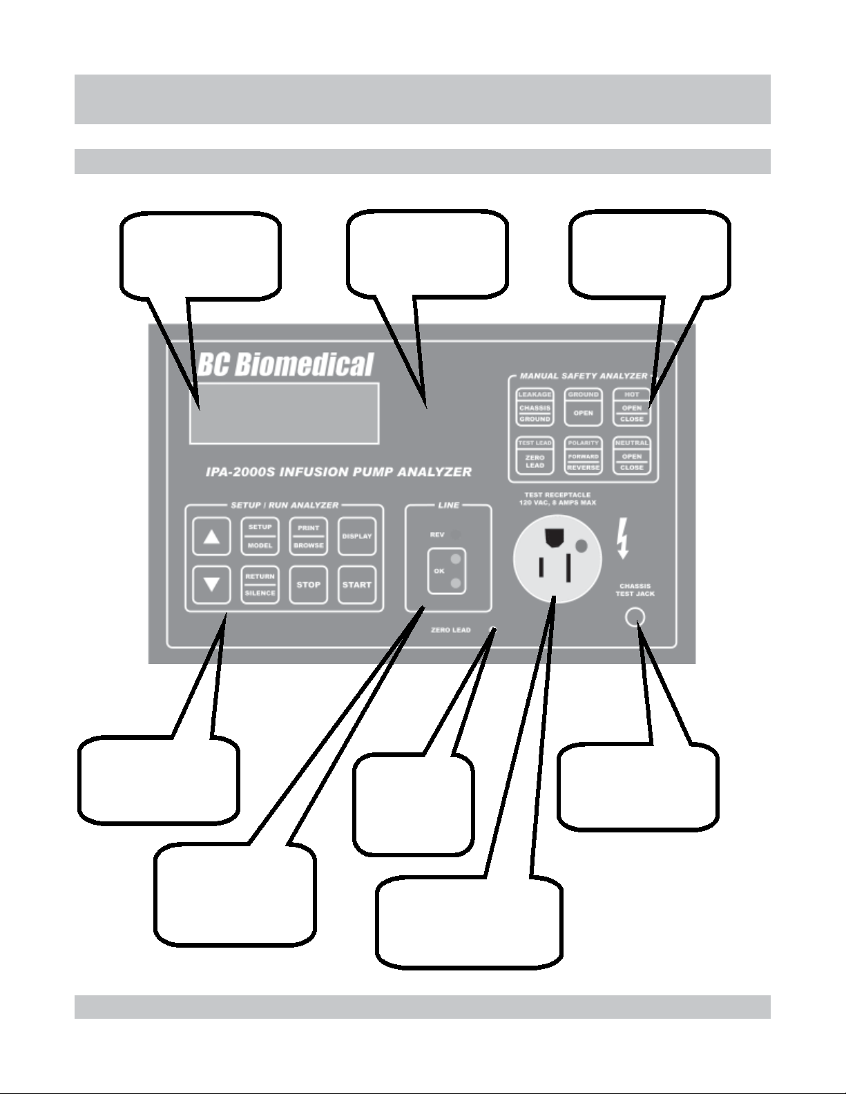
Display window that
shows needed
information concerning
tests and data.
Audio Transducer that
provides key clicks,
warning and alarm tones
(behind faceplate)
Keypad for use during
Manual Safety
Analyzer test.
Keypad for setup,
running of tests, data
processing and printing.
Light Emitting Diodes
(LEDs) that indicate
the status of the line
powering the unit.
1-6
Stud used when
zeroing the test
lead during a
Safety Analyzer
test.
Test Receptacle Outlet
used to plug in the
Device Under Test (DUT)
power cord during a Safety
Analyzer test.
Banana jack used to
plug in the test lead
during a Safety
Analyzer test.
UNIT FRONT-PANEL
Page 17
INSTRINSTR
INSTR
INSTRINSTR
UMENT OUMENT O
UMENT O
UMENT OUMENT O
UNIT FRONT-PANEL CONTROLS
VERVER
VER
VERVER
VIEWVIEW
VIEW
VIEWVIEW
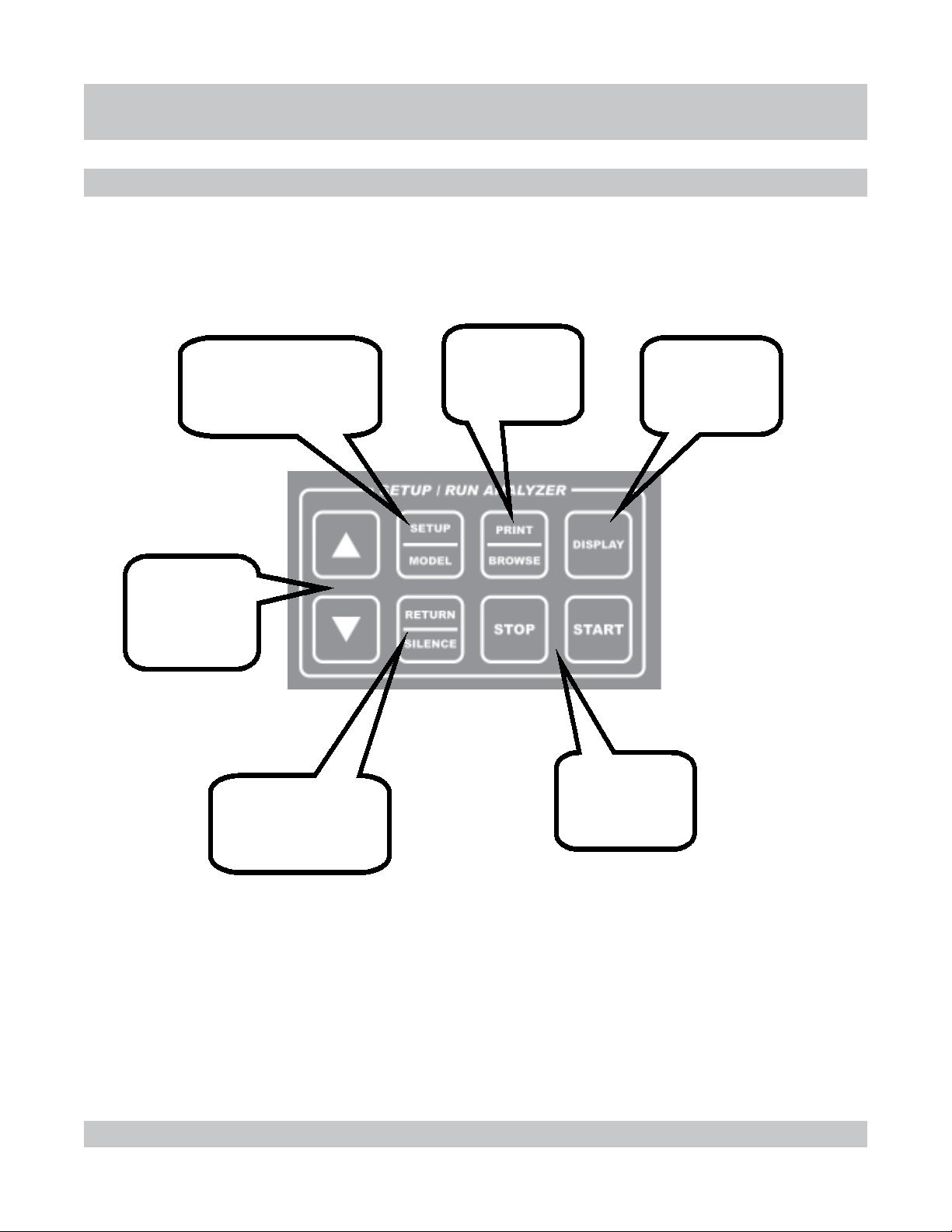
Used to scroll up
and down while
viewing data or
selecting various
options.
Used from main screen
to enter setup and edit
modes. Used from test
screens to enter model
selection and edit modes.
Used to browse
and print Datalogs.
Used to toggle
through channels.
1-7
Used to enter edited
choices and return to
view screens.
Used to silence alarms.
Used to start and
stop tests.
UNIT FRONT-PANEL CONTROLS
Page 18
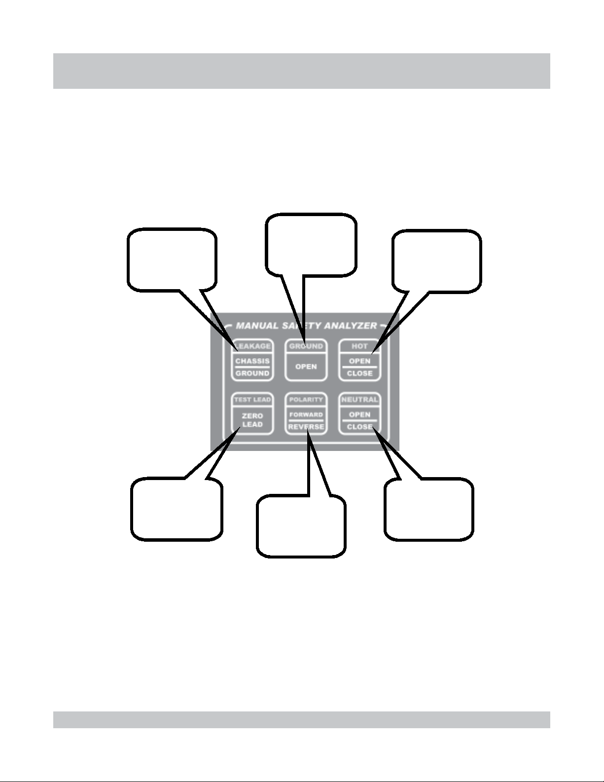
Toggles the
leakage being
tested between
chassis and
ground.
Momentarily
opens and closes
the ground lead
of the Test
Receptacle outlet.
INSTRINSTR
INSTR
INSTRINSTR
UMENT OUMENT O
UMENT O
UMENT OUMENT O
Opens and closes
the hot lead of the
Test Receptacle
outlet.
VERVER
VER
VERVER
VIEWVIEW
VIEW
VIEWVIEW
Used to zero the
test lead that will
be used to measure
chassis leakage.
Changes the
polarity of the
Test Receptacle
outlet.
Opens and closes
the neutral lead
of the Test
Receptacle outlet.
1-8
UNIT FRONT-PANEL CONTROLS
Page 19
INSTRINSTR
INSTR
INSTRINSTR
UNIT BACK-PANEL
UMENT OUMENT O
UMENT O
UMENT OUMENT O
VERVER
VER
VERVER
VIEWVIEW
VIEW
VIEWVIEW
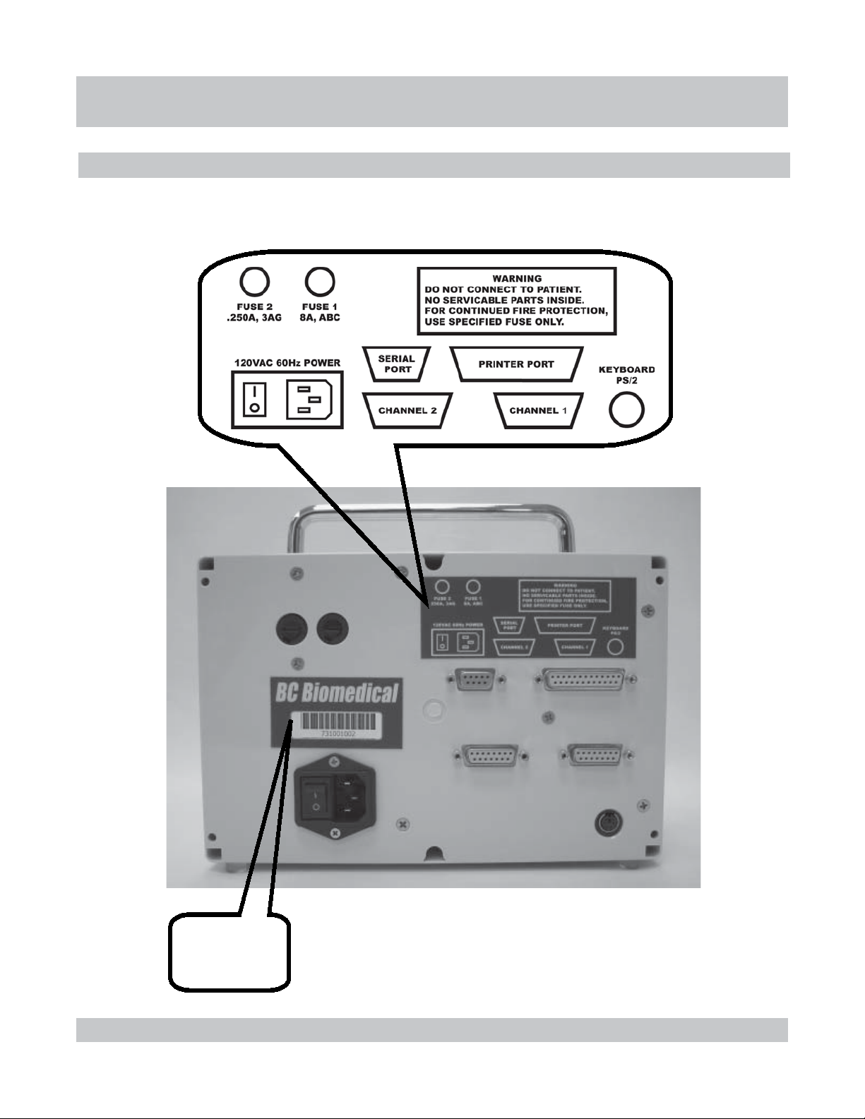
1-9
Model / Serial
Number and
barcode for
the unit.
UNIT BACK-PANEL
Page 20
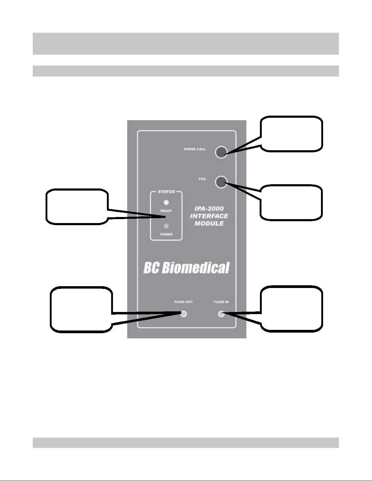
Status Light Emitting
Diodes (LEDs) that
show power and
normal status.
INSTRINSTR
INSTR
INSTRINSTR
MODULE FRONT-PANEL
UMENT OUMENT O
UMENT O
UMENT OUMENT O
Nurse Call connector
for optional use
during Distal
Occlusion Test.
PCA connector
for use during
Flow-PCATest.
VERVER
VER
VERVER
VIEWVIEW
VIEW
VIEWVIEW
Luer Lock connector
for Fluid Out drain
tube with 1/4 “ ID and
air vent that goes to
drainage container.
1-10
Luer Lock connector
for Inlet Valve for
Fluid In tube that
comes from
DUT out.
MODULE FRONT-PANEL
Page 21
INSTRINSTR
INSTR
INSTRINSTR
UMENT OUMENT O
UMENT O
UMENT OUMENT O
VERVER
VER
VERVER
VIEWVIEW
VIEW
VIEWVIEW
MODULE BACK-PANEL
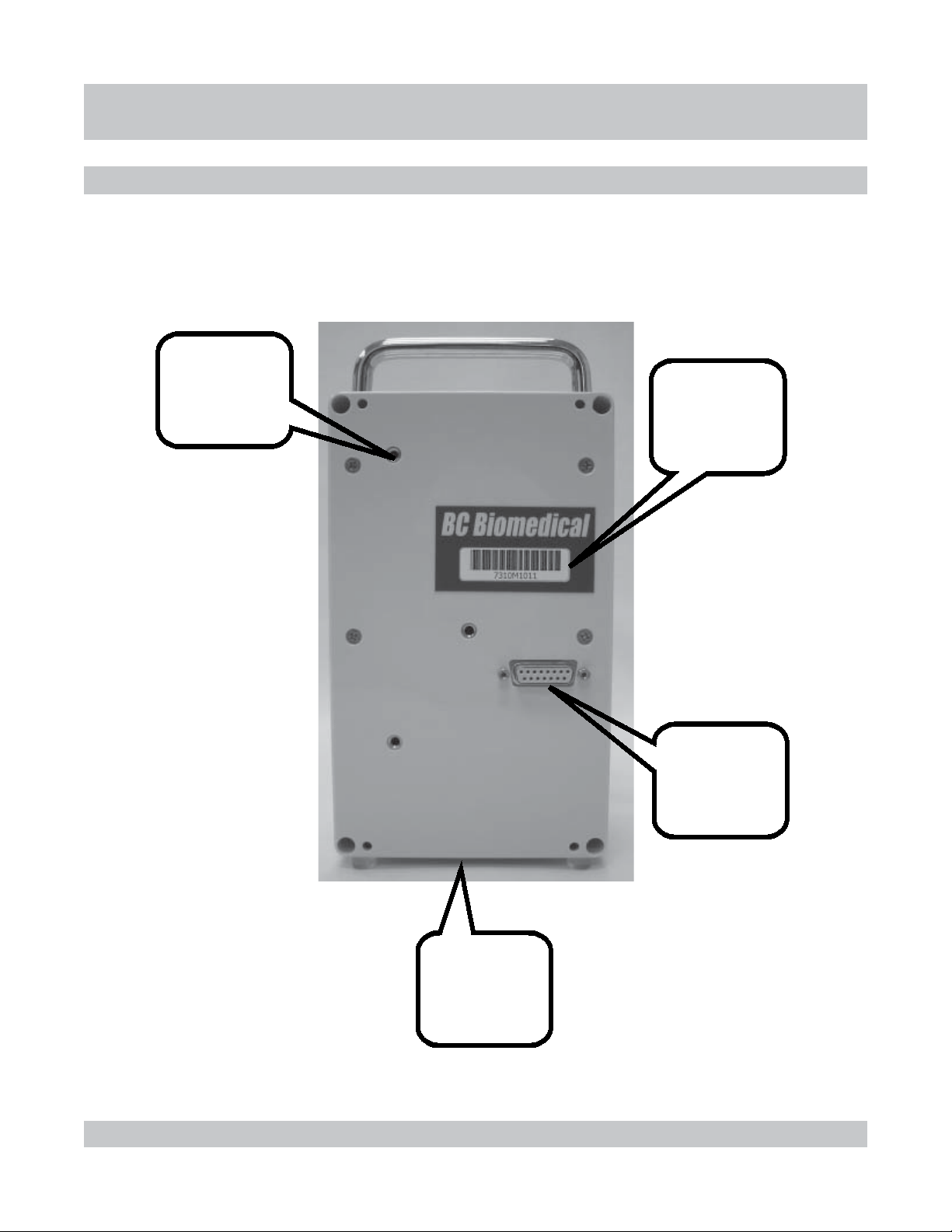
Threaded holes
for optional pole
mounting
bracket.
Model / Serial
Number and
barcode for
the unit.
Connection for
DB15 cable to
unit.
1-11
Threaded hole
on bottom for
optional stand.
MODULE BACK-PANEL
Page 22

COMMERCIAL AND MAIN SCREENS
NOTES:
CThe Commercial screen displays
while the system is initiating.
CThe unit model and program version
appear on this screen.
NOTES:
CThe Main screen displays after
approximately 3 seconds.
CFrom this screen, central access
to the Datalogger can be obtained
with or without modules attached,
current active alarms may be
viewed, the Setup mode can be
accessed and test screens can be
toggled to.
CThe Display key is used to cycle
back to the Main screen from other
locations.
CThe time of day clock and date
appear on this screen, the format
and value of which can be selected
in User Setup.
INSTRINSTR
INSTR
INSTRINSTR
INFUSION ANALYZER
MODEL IPA-2000S
Month Day, Year
UMENT OUMENT O
UMENT O
UMENT OUMENT O
BC GROUP
VER X.X
IPA-2000S
00:00:00
VERVER
VER
VERVER
VIEWVIEW
VIEW
VIEWVIEW
1-12
COMMERCIAL AND MAIN SCREENS
Page 23

CONNECTIONSCONNECTIONS
CONNECTIONS
CONNECTIONSCONNECTIONS
CONNECTIONS OVERVIEW
This section gives a pictorial overview and explanation of
connections for the unit and modules.
Included are:
CMain Unit to Module connection
CMain Unit to Printer connection
CMain Unit to Keyboard connection
CMain Unit Computer connection
CSystem to DUT for Infusion Pump Analysis
CSystem to DUT for Safety Analysis
1-13
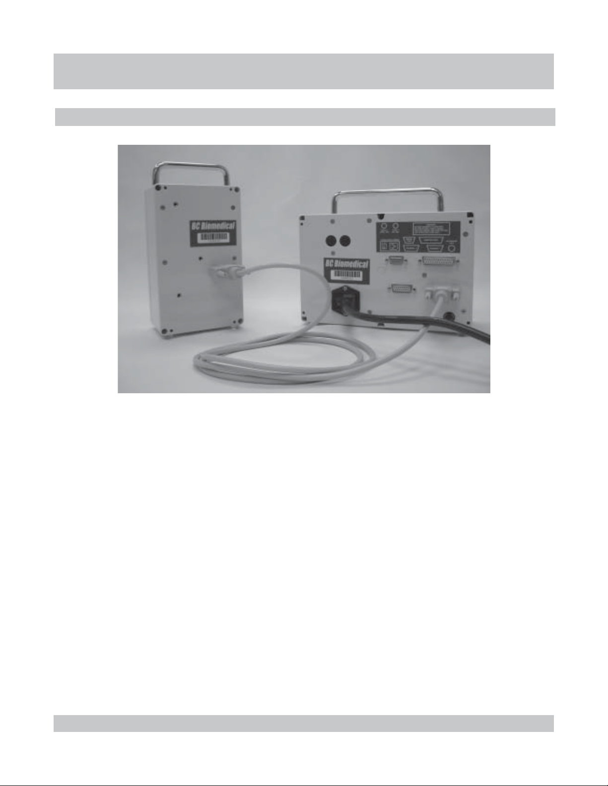
CONNECTIONS OVERVIEW
Page 24
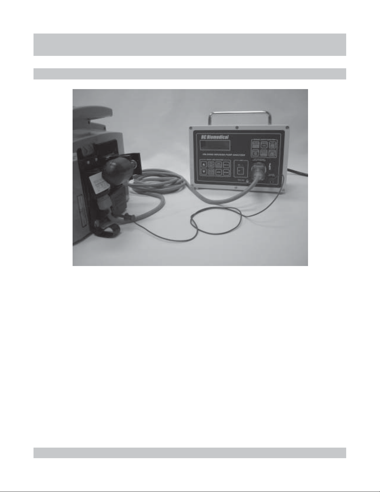
MODULE CONNECTION
CONNECTIONSCONNECTIONS
CONNECTIONS
CONNECTIONSCONNECTIONS
1-14
CModules are connected during use of the Infusion Analyzer.
CA module is connected using a DB15 cable from the port on the back of the
module to one of the Channel ports on the back of the unit.
CModules are interchangeable and can be connected to either Channel 1 or 2.
MODULE CONNECTION
Page 25
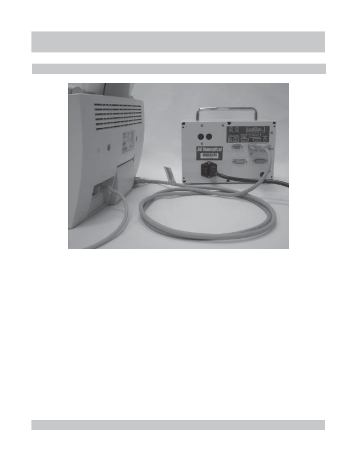
PRINTER CONNECTION
CONNECTIONSCONNECTIONS
CONNECTIONS
CONNECTIONSCONNECTIONS
1-15
CAny standard printer can be connected to the unit using a Centronics
parallel cable (IEEE-1284).
CThe printer is connected from the parallel port of the printer to the parallel
port of the unit.
C A serial printer can also be connected to the unit using an RS232 cable
(DB9) .
CThe printer is connected from the serial port of the printer to the serial port
of the unit.
C(See PRINTING REPORTS for details on how to print.)
PRINTER CONNECTION
Page 26

KEYBOARD CONNECTION
CONNECTIONSCONNECTIONS
CONNECTIONS
CONNECTIONSCONNECTIONS
1-16
CAny PS/2 style keyboard can be connected to the unit.
CThe keyboard cable is connected to the PS/2 port of the unit.
C(Optional) Labels for the keyboard illustrate how the Function and Arrow
keys correspond to the controls on the unit.
CFull remote control of the unit can be obtained through use of the keyboard.
CThe standard keys can then be used to type in Manufacturer, Model, S/N,
Department and Location to help identify tests in the Datalogger and printouts.
(See MODEL SELECTION for details.)
KEYBOARD CONNECTION
Page 27
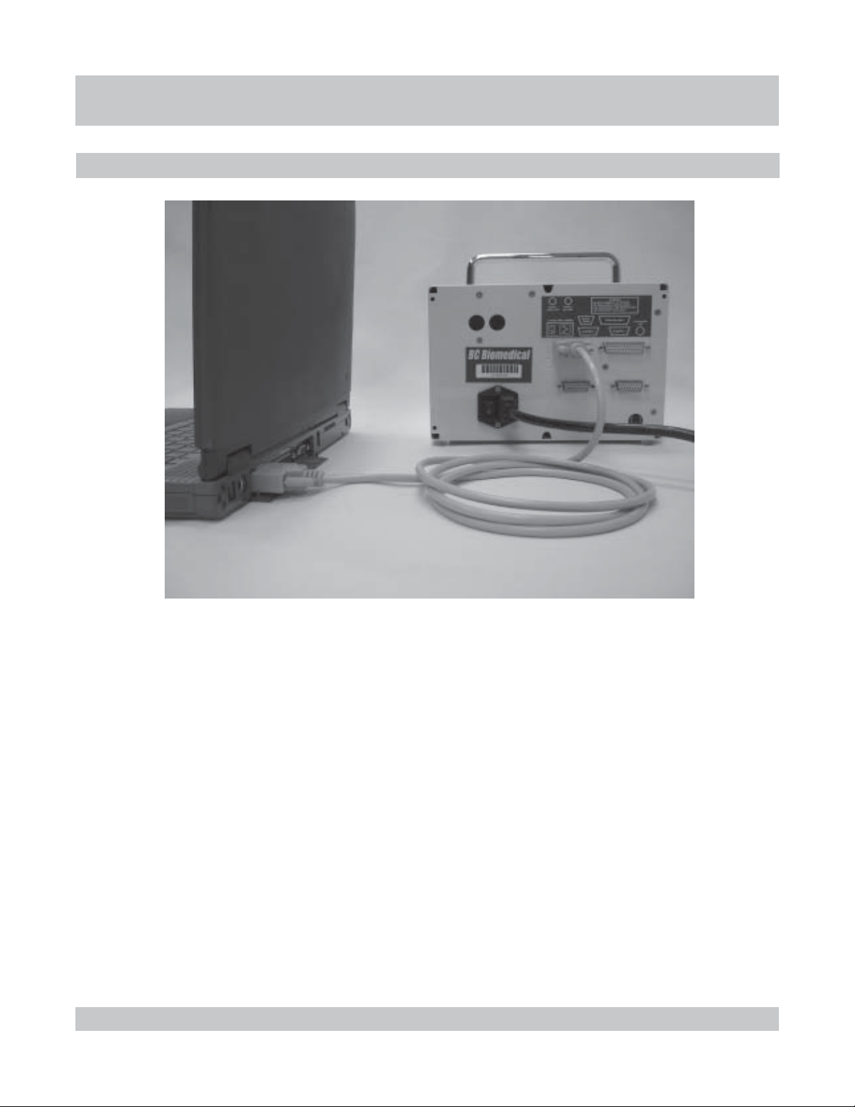
COMPUTER CONNECTION
CONNECTIONSCONNECTIONS
CONNECTIONS
CONNECTIONSCONNECTIONS
1-17
CAn RS232 cable (DB9) can be used to interface the unit with a computer.
CThe RS232 cable is connected from a communication port on the computer
to the Serial Port on the unit.
CThe RS232 connection can be utilized to download reports from the unit.
CThe RS232 connection can be utilized to load updated programs to the
unit. (See FLASH for details.)
COMPUTER CONNECTION
Page 28
CONNECTIONSCONNECTIONS
CONNECTIONS
CONNECTIONSCONNECTIONS
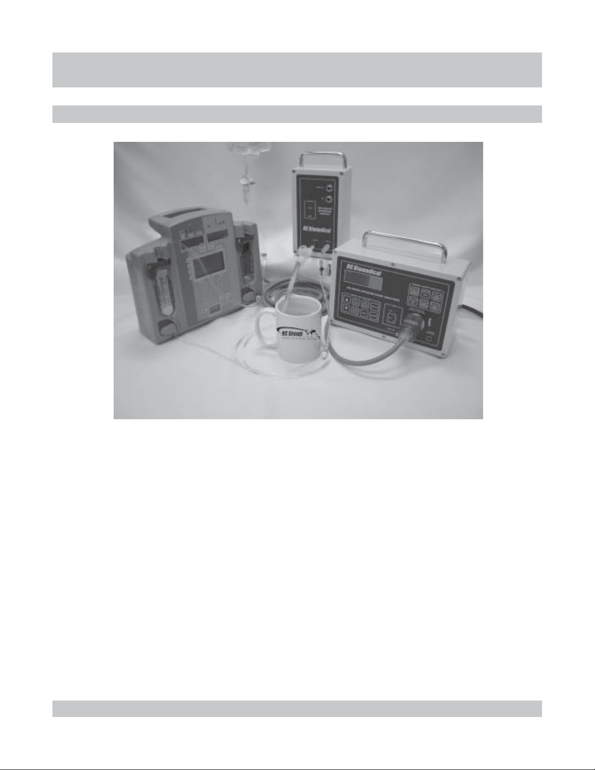
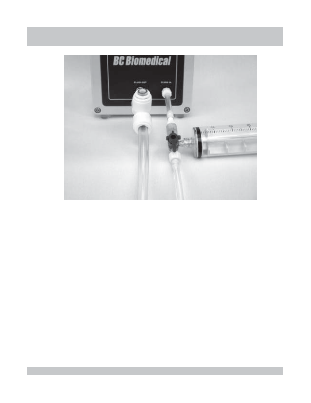
INFUSION PUMP ANALYZER / DUT CONNECTION
1-18
CFor Infusion Analyzer Tests, the following connections must be made:
CInterface module to unit
CFluid source to device under test (DUT)
CInlet Valve to module Fluid In
CDUT Fluid Out to Inlet Valve
CModule Fluid Out 1/4” ID Drain Tube with air vent
to drainage container
CDUT power cord to Unit receptacle
CUnit power cord to wall receptacle
INFUSION PUMP ANALYZER / DUT CONNECTION
Page 29
CONNECTIONSCONNECTIONS
CONNECTIONS
CONNECTIONSCONNECTIONS
1-19
CFor Infusion Analyzer Tests, the following module connections must be made:
CInlet Valve to module Fluid In
CDUT Fluid Out to Inlet Valve
CModule Fluid Out 1/4” ID Drain Tube with air vent
to drainage container
INFUSION PUMP ANALYZER / DUT CONNECTION
Page 30
SAFETY ANALYZER / DUT CONNECTION
CONNECTIONSCONNECTIONS
CONNECTIONS
CONNECTIONSCONNECTIONS
1-20
CFor Safety Analyzer Tests, the following connections must be made:
CTest lead into banana jack on unit.
CTest lead hooked to chassis of device under test (DUT)
(See Pump Manufacturer Manual for requirements or special
instructions for placement.)
CDUT power cord to Unit receptacle
CUnit power cord to wall receptacle
SAFETY ANALYZER / DUT CONNECTION
Page 31

SPECIFICASPECIFICA
SPECIFICA
SPECIFICASPECIFICA
SPECIFICATIONS
The following is a table showing the specifications for the Infusion Analyzer:
TIONSTIONS
TIONS
TIONSTIONS
EGNARWOLF
)EGAREVA(
YCARUCCAWOLF
EGNAREMULOV
YCARUCCAEMULOV
ERUSSERPNOISULCCO
SLENNAHCFOREBMUN
rh/Lm9.999-5.0
DSL-/+gnidaerfo%2-/+
emuloVmuminiMLm01
Lm99.999-70.0
DSL-/+gnidaerfo%2-/+
emuloVmuminiMLm01
ISP53-0
DSL-/+gnidaerfo%5-/+
mumixaM2
The following is a table showing the specifications for the Safety Analyzer:
EGATLOVENIL
)G-LderusaeM(
TNERRUCDAOL
ECNATSISERDNUORG
CAV041-09
DSL1-/+SF%2-/+
A0.8-2.0
DSL1-/+SF%5-/+
00.02-00.0 Ω
DSL1-/+SF%1-/+
1-21
TNERRUCEGAKAEL
).daoltsetIMAAfostniartsnocottcejbusesnopserycneuqerF(
zHK00.1-zH52&CD
zHK001-zHK00.1
zHM00.1-zHK001
0002-1 µA
0001-1(DSL1-/+SF%0.1-/+ µ )A
0001>(DSL1-/+SF%0.2-/+ µ )A
DSL1-/+SF%5.2-/+
DSL1-/+SF%0.5-/+
The following is a table showing the general specifications for the unit:
CAV021@A56.
TNEMERIUQERREWOP
%01-ot%02+
zH06/05
SPECIFICATIONS
Page 32

This Page Intentionally Left Blank.
1-22
Page 33

GENERAL OPERAGENERAL OPERA
GENERAL OPERA
GENERAL OPERAGENERAL OPERA
PART 2 : GENERAL OPERATIONS
This section covers the general operations of the unit.
Included are:
CHow to Setup the System
CAdministration
CUser
CHow to Select Model Information
CHow to Prime the System
CHow the Datalogger Generally Works
TIONSTIONS
TIONS
TIONSTIONS
CHow to Print a Report
CHow System Memory Works
CHow Alarms Work
CHow to Flash a Program
2-1
PART 2 : GENERAL OPERATIONS
Page 34

ADMINISTRAADMINISTRA
ADMINISTRA
ADMINISTRAADMINISTRA
ADMINISTRATION SETUP OVERVIEW
TION SETUPTION SETUP
TION SETUP
TION SETUPTION SETUP
The system is configured to specific application requirements
via a set of Administration parameters. This section covers
the general setting of those parameters, including how to
access, change and save. There is also a listing of all
available Settings and Choices and an explanation of their
use.
The following is an outline of the steps that are involved in
selecting the Administration Setup for the system.
ADMINISTRATION SETUP
CBegin from Main Screen
CEnter Setup Screen
CView Setup Parameters
CChoose Setup Parameter to Edit
CGo into Setup Edit Mode
CScroll to Desired Choice for Parameter
CEdit Other Parameters
CSave and Return to Main Screen
2-2
ADMINISTRATION SETUP OVERVIEW
Page 35

ADMINISTRAADMINISTRA
ADMINISTRA
ADMINISTRAADMINISTRA
ADMINISTRATION SETUP
TION SETUPTION SETUP
TION SETUP
TION SETUPTION SETUP
STEP 1
STEP 2
9
9
Begin from Main Screen
The Setup screens for the unit are accessed through the Main
screen. Use to toggle to the Main screen.
IPA-2000S
Month Day, Year
00:00:00
Enter Setup Screen
Use to enter the Access Code screen for Setup for
the system.
AVAILABLE ACCESS CODES
01 - 999901 - 9999
01 - 9999
01 - 999901 - 9999
NOTE:
CUnit is shipped with Administration
Stack access code set to 02.
2-3
Enter Access Code
L
Use to enter the access code.
After setting the code, use to enter the Administration
Setup-View screen for the system.
00
ADMINISTRATION SETUP
Page 36

ADMINISTRAADMINISTRA
ADMINISTRA
ADMINISTRAADMINISTRA
TION SETUPTION SETUP
TION SETUP
TION SETUPTION SETUP
STEP 3
9
NOTES:
CThe system’s function is controlled
by a number of setup parameters.
CThe selected parameter is
indicated by the flashing cursor.
CThe screen displays any three
consecutive data lines.
CSome values are not shown when
using AAMI or IEC specifications.
AVAILABLE SETUP PARAMETERS
SOFTWARESOFTWARE
SOFTWARE
SOFTWARESOFTWARE
GROUND OFFSETGROUND OFFSET
GROUND OFFSET
GROUND OFFSETGROUND OFFSET
SAFETY SPECSSAFETY SPECS
SAFETY SPECS
SAFETY SPECSSAFETY SPECS
GROUND RESISTGROUND RESIST
GROUND RESIST
GROUND RESISTGROUND RESIST
NORM GND CURNORM GND CUR
NORM GND CUR
NORM GND CURNORM GND CUR
FF
AA
ULUL
T GND CURT GND CUR
F
A
UL
T GND CUR
FF
AA
ULUL
T GND CURT GND CUR
NORM CHS CURNORM CHS CUR
NORM CHS CUR
NORM CHS CURNORM CHS CUR
FF
AA
ULUL
T CHS CURT CHS CUR
F
A
UL
T CHS CUR
FF
AA
ULUL
T CHS CURT CHS CUR
LINE LINE
LINE
LINE LINE
CLEAR MODELSCLEAR MODELS
CLEAR MODELS
CLEAR MODELSCLEAR MODELS
ALLOW MODEL EDITALLOW MODEL EDIT
ALLOW MODEL EDIT
ALLOW MODEL EDITALLOW MODEL EDIT
CH 1 SERIAL NUMCH 1 SERIAL NUM
CH 1 SERIAL NUM
CH 1 SERIAL NUMCH 1 SERIAL NUM
CH 2 SERIAL NUMCH 2 SERIAL NUM
CH 2 SERIAL NUM
CH 2 SERIAL NUMCH 2 SERIAL NUM
ACCESS CODE #2ACCESS CODE #2
ACCESS CODE #2
ACCESS CODE #2ACCESS CODE #2
VV
V
VV
OLOL
OL
OLOL
TT
AA
GEGE
T
A
GE
TT
AA
GEGE
View Setup Parameters
Use to scroll the available parameters.
L
ADMIN SETUP - VIEW
SOFTWARE DT7310CB
GROUND OFFSET .02
ΩΩ
Ω
ΩΩ
SAFETY SPECS CUSTOM
2-4
ADMINISTRATION SETUP
Page 37

ADMINISTRAADMINISTRA
ADMINISTRA
ADMINISTRAADMINISTRA
TION SETUPTION SETUP
TION SETUP
TION SETUPTION SETUP
The following is a table showing descriptions and choices for available parameters:
RETEMARAP NOITPIRCSED SECIOHC
ERAWTFOS
TESFFODNUORG
)YLNOS0002(
SCEPSYTEFAS
)YLNOS0002(
SERDNUORG
)YLNOS0002(
RUCDNGMRON
)YLNOS0002(
RUCDNGTLUAF
)YLNOS0002(
RUCSHCMRON
)YLNOS0002(
RUCSHCTLUAF
)YLNOS0002(
EGATLOVENIL
)YLNOS0002(
SLEDOMRAELC
LEDOMWOLLA
TIDE
MUNLAIRES1HC
MUNLAIRES2HC
EDOCSSECCA
2#
( edomputeSehtgnitixenopuenoD )
IMDA( neercsputeSmorfkcatSN )
tinuehtgninnur
.daeLtseTdnuorG
.noitarbilac
.MOTSUCottessiretemarapSCEPS
.MOTSUCottessiretemarapSCEPS
.MOTSUCottessiretemarap
.MOTSUC
SLEDOMehtllaniderotsatadehtllasesarE
.mehtegnahctonnac
1lennahC
2lennahC
sitahterawtfosehtrofrebmunmargorptnerrucehtsyalpsiD
ehtrofetasnepmocotdesueboteulavdexifaswollA
ehtfoecnatsiserdaeltsetdnalanretnidradnats
rehtruflliwnoitarbilaCdaeLtseTdnuorGehT:ETON
ylpmiserehgnitteslaunamA.eulavsihtrofetasnepmoc
lautcaehterofebtluserehtotresolceulavesabehtsekam
lacirtcelEehtrofseulavLIAF/SSAPehtrehtehwsenimreteD
,)motsuC(seulavdetceles-resunodesaberarezylanAytefaS
.sretemarapCEIrosretemarapdradnats3991IMAA
ehtniecnatsiserdnuorgelbawollamumixamehtsenimreteD
nehwelbaliavaylnosiretemarapsihT.tsetytefaSlacirtcelE
.MOTSUCottessiretemarapSCEPSYTEFASeht
nitnerrucegakaeldnuorgelbawollamumixamehtsenimreteD
.snoitidnocelcatpecerlamronrednutsetytefaSlacirtcelEeht
TUD,ytiralopdesrever/drawroffotsisnocsnoitidnoclamroN
snoitcennoclartueNdnatoHhtobdnaFFOdnaNOrewop
YTEFASehtnehwelbaliavaylnosiretemarapsihT.tcatni
nitnerrucegakaeldnuorgelbawollamumixamehtsenimreteD
.snoitidnocelcatpecertluafrednutsetytefaSlacirtcelEeht
TUD,ytiralopdesrever/drawroffotsisnocsnoitidnoctluaF
snoitcennoclartueNrotoHehtrehtiednaFFOdnaNOrewop
YTEFASehtnehwelbaliavaylnosiretemarapsihT.nepo
tnerrucegakaelsissahcelbawollamumixamehtsenimreteD
elcatpecerlamronrednutsetytefaSlacirtcelEehtni
desrever/drawroffotsisnocsnoitidnoclamroN.snoitidnoc
sihT.tcatnidnuorGdnaFFOdnaNOrewopTUD,ytiralop
SCEPSYTEFASehtnehwelbaliavaylnosiretemarap
tnerrucegakaelsissahcelbawollamumixamehtsenimreteD
.snoitidnocelcatpecertluafrednutsetytefaSlacirtcelEehtni
TUD,ytiralopdesrever/drawroffotsisnocsnoitidnoctluaF
siretemarapsihT.nepodnuorGdnaFFOdnaNOrewop
ottessiretemarapSCEPSYTEFASehtnehwelbaliavaylno
eniLrofdesU.rezylanAytefaSehtrofegatlovenilehtstceleS
.stsetrezylanAytefaSdetamotuAehtrofnoitadilavegatloV
resuehtossgnitteselbatledoMehtkcolotsnaemasedivorP
otdetcennoceludomehtforebmunlairesehtsyalpsiD
).eludomwenfonoitcetednopuenodyllacitamotuA(
otdetcennoceludomehtforebmunlairesehtsyalpsiD
).eludomwenfonoitcetednopuenodyllacitamotuA(
kcatssihtotniyrtnerofdedeenedocsseccaehtsteS
00.2-00.0 Ω
0002-0 µA
0002-0 µA
0002-0 µA
0002-0 µA
V001
V021
ON
SEY
ON
SEY
9999-0
YLNODAER
02.0+ot02.0- Ω
CEIroIMAA,motsuC
YLNODAER
YLNODAER
2-5
ADMINISTRATION SETUP
Page 38

ADMINISTRAADMINISTRA
ADMINISTRA
ADMINISTRAADMINISTRA
TION SETUPTION SETUP
TION SETUP
TION SETUPTION SETUP
STEP 4
NOTES:
C The selected parameter is
indicated by the flashing cursor.
C Each parameter can be edited
separately, using these same steps.
STEP 5
NOTE:
CIn the Edit mode, the flashing line
cursor will change to a box.
9
9
Choose Setup Parameter to Edit
Use to scroll to the desired parameter to edit.
ADMIN SETUP - VIEW
SOFTWARE 7310L09F
GROUND OFFSET .02
SAFETY SPECS CUSTOM
ΩΩ
Ω
ΩΩ
Go into Setup Edit Mode
When the cursor is under the desired parameter,
use to enter the Edit mode.
2-6
ADMIN SETUP - EDIT
SOFTWARE 7310L09F
GROUND OFFSET .02
SAFETY SPECS CUSTOM
ADMINISTRATION SETUP
ΩΩ
Ω
ΩΩ
Page 39

ADMINISTRAADMINISTRA
ADMINISTRA
ADMINISTRAADMINISTRA
TION SETUPTION SETUP
TION SETUP
TION SETUPTION SETUP
STEP 6
STEP 7
9
9
Scroll to Desired Choice for Parameter
Use to scroll through the choices for the
parameter.
ADMIN SETUP - EDIT
SOFTWARE 7310L09F
GROUND OFFSET .01
SAFETY SPECS CUSTOM
Enter Choice for Parameter
Use to enter the new setting for the parameter and
return to the View mode.
ΩΩ
Ω
ΩΩ
STEP 8
2-7
9
ADMIN SETUP - VIEW
SOFTWARE 7310L09F
GROUND OFFSET .01
SAFETY SPECS CUSTOM
Edit Other Parameters
Repeat steps 3 through 7 to edit any other parameters.
ADMINISTRATION SETUP
ΩΩ
Ω
ΩΩ
Page 40

ADMINISTRAADMINISTRA
ADMINISTRA
ADMINISTRAADMINISTRA
TION SETUPTION SETUP
TION SETUP
TION SETUPTION SETUP
STEP 9
9
Save and Return to Main Screen
Once all the parameters show the desired settings,
use to save and return to the Main screen.
**SAVE MODE**
IPA-2000S
Month Day, Year
00:00:00
2-8
ADMINISTRATION SETUP
Page 41

USER SETUPUSER SETUP
USER SETUP
USER SETUPUSER SETUP
USER SETUP OVERVIEW
The system is configured to specific use requirements via a
set of User parameters. This section covers the general
setting of those parameters, including how to access, change
and save. There is also a listing of all available Settings and
Choices and an explanation of their use.
The following is an outline of the steps that are involved in
selecting the User Setup for the system.
USER SETUP
CBegin from Main Screen
CEnter Setup Screen
CView Setup Parameters
CChoose Setup Parameter to Edit
CGo into Setup Edit Mode
CScroll to Desired Choice for Parameter
CEdit Other Parameters
CSave and Return to Main Screen
2-9
USER SETUP OVERVIEW
Page 42

USER SETUP
USER SETUPUSER SETUP
USER SETUP
USER SETUPUSER SETUP
STEP 1
STEP 2
9
9
Begin from Main Screen
The Setup screens for the unit are accessed through the
Main screen. Use to toggle to the Main screen.
IPA-2000S
Month Day, Year
00:00:00
Enter Setup Screen
Use to enter the Access Code screen for Setup for
the system.
AVAILABLE ACCESS CODES
01 - 999901 - 9999
01 - 9999
01 - 999901 - 9999
NOTE:
CUnit is shipped with User Setup
access code set to 00.
2-10
Enter Access Code
L
Use to enter the access code.
After setting the code, use to enter the User
Setup-View screen for the system.
00
USER SETUP
Page 43

USER SETUPUSER SETUP
USER SETUP
USER SETUPUSER SETUP
STEP 3
9
NOTES:
CThe system’s function is controlled
by a number of setup parameters.
C The selected parameter is
indicated by the flashing cursor.
CThe screen displays any three
consecutive data lines.
AVAILABLE SETUP PARAMETERS
AIR PURGEAIR PURGE
AIR PURGE
AIR PURGEAIR PURGE
UNITS FLOWUNITS FLOW
UNITS FLOW
UNITS FLOWUNITS FLOW
UNITS PRESSUNITS PRESS
UNITS PRESS
UNITS PRESSUNITS PRESS
HIGH FLOWHIGH FLOW
HIGH FLOW
HIGH FLOWHIGH FLOW
LOW FLOWLOW FLOW
LOW FLOW
LOW FLOWLOW FLOW
TIMETIME
TIME
TIMETIME
DD
AA
YY
D
A
Y
DD
AA
YY
MONTHMONTH
MONTH
MONTHMONTH
YEARYEAR
YEAR
YEARYEAR
DD
AA
TE FORMATE FORMA
D
A
TE FORMA
DD
AA
TE FORMATE FORMA
BB
AA
UD RAUD RA
B
A
UD RA
BB
AA
UD RAUD RA
PRINT MODEPRINT MODE
PRINT MODE
PRINT MODEPRINT MODE
PRINT PORTPRINT PORT
PRINT PORT
PRINT PORTPRINT PORT
PRINT FORMAPRINT FORMA
PRINT FORMA
PRINT FORMAPRINT FORMA
PRINT PRINT
PRINT
PRINT PRINT
LL
OG INTEROG INTER
L
OG INTER
LL
OG INTEROG INTER
LL
OG DOG D
L
OG D
LL
OG DOG D
CLEAR DCLEAR D
CLEAR D
CLEAR DCLEAR D
ALARM SCANALARM SCAN
ALARM SCAN
ALARM SCANALARM SCAN
ACCESS CODE #1ACCESS CODE #1
ACCESS CODE #1
ACCESS CODE #1ACCESS CODE #1
ALL DALL D
ALL D
ALL DALL D
AA
TT
A
T
AA
TT
TT
T
TT
TETE
TE
TETE
TT
T
TT
AA
TT
A
T
AA
TT
VV
ALAL
V
AL
VV
ALAL
A EVERA EVER
A EVER
A EVERA EVER
AA
TT
AA
A
T
A
AA
TT
AA
AA
A
AA
YY
Y
YY
View Setup Parameters
Use to scroll the available parameters.
USER SETUP - VIEW
UNITS FLOW cc/hr
L
UNITS PRESS PSI
HIGH FLOW 0.0 cc/hr
2-11
USER SETUP
Page 44

USER SETUPUSER SETUP
USER SETUP
USER SETUPUSER SETUP
The following is a table showing descriptions and choices for available parameters:
RETEMARAP NOITPIRCSED SECIOHC
EGRUPRIA.tinuehttuoyrdotriawollaotadionelosnepootdesU
WOLFSTINU
SSERPSTINU gnidaererusserpehtrofstinucifitneicsehtfonoitcelesswollA
WOLFHGIH
WOLFWOL
EMIT
YADkcolcemit-laerehtfohtnomehtfoyadehtsteS13-10
HTNOMkcolcemit-laerehtforaeyehtfohtnomehtsteS REBMECED-YRAUNAJ
RAEYkcolcemit-laerehtforaeyehtsteS9902-0002
TAMROFETADkcolcemit-laerehtfoetadehtfotamrofehtsteS
ETARDUABlocotorPsnoitacinummoCehtrof'DUAB'ehtsteS
EDOMTNIRP
TROPTNIRPepyttropretnirpehtsteS
TAMROFTNIRPtamroftuotnirpehtrofsnmulocforebmunehtsteS
ATADLLATNIRP
LAVRETNIGOL
YREVEATADGOL
ATADRAELC
1#
( ONotstesernehtedomputeSehtgnitixenopuenoD )
NACSMRALA
EDOCSSECCA
(tnioptessihtwoleb
( kcatSretemaraPresU )
gnidaerwolfeht
tsetgnirud etavitcalliwmralAwolFwoL,)
kcolcemit-laerehtfoyadfoemitsteS
SS:MM:HH
edomtnirpfonoitcelesswollA
yektnirPgnisudetnirpataD-launaM
detnirpyllacitamotuagolataD-ataD
tsetfodneta
.emitnoitcellocataDlatotdnapxe
golataDniderotstniopataD
SS:MM
.neercSniaMehtnidellorcs
rofstinutnemerusaemcifitneicsehtfonoitcelesswollA
siwolfderusaemfI.tniopteSmralAwolFhgiHehtsretnE
etavitcalliwmralAwolFhgiH,tnioptessihtevoba
detnirpyllacitamotuayrammuS-yrammuS
detnirpyllacitamotuagolataDdnayrammuS-htoB
sgolataDehtllaniderotsetadehtllastnirP
golataDehtotniataDgnirotsrofedomehtstceleS
detcellocnehwderotsyllacitamotuaataD-otuA
sgolataDehtllaniderotsatadehtllasesarE
kcatssihtotniyrtnerofdedeenedocsseccaehtsteS
( etanimilelliw0otgnitteS
sllafwolfderusaemfI.tniopteSmralAwolFwoLehtsretnE
( etanimilelliw0otgnitteS
)ONotstesernehtedomputeSehtgnitixenopuenoD(
ottesebnactniopataDhcaeneewteblavretniemit-launaM
hcaeneewtebsdnocesdnasetunimniemitehtstceleS
( goLnehwelbaliavaylnO
yllacitamotuaerasmralaevitcahcihwtaetarehtsenimreteD
NO
FFO
rh/Lm
rh/cc
H"ISP
2
MTAAPk
0042
0084
0069
00882
00675
002511
ATAD
HTOB
LAIRES
ENON
LOC08
LOC04
SEY
ON
OTUA
ON
SEY
9999-0
F°06@O
C°0@gHmm
rh/Lm9.999-0
.erutaefmralasiht )
rh/Lm9.999-0
.erutaefmralasiht )
95:95:32-00:00:00
YY/DD/MM
YY/MM/DD
LAUNAM
YRAMMUS
LELLARAP
LAUNAM
95:99-10:00
.launaMotteslavretnI )
ces52-1
2-12
USER SETUP
Page 45

USER SETUPUSER SETUP
USER SETUP
USER SETUPUSER SETUP
STEP 4
NOTES:
CThe selected parameter is indicated
by the flashing cursor.
CEach parameter can be edited
separately, using these same steps.
STEP 5
NOTE:
CIn the Edit mode, the flashing line
cursor will change to a box.
9
9
Choose Setup Parameter to Edit
Use to scroll to the desired parameter to
edit.
USER SETUP - VIEW
UNITS FLOW cc/hr
UNITS PRESS PSI
HIGH FLOW 0.0 cc/hr
Go into Setup Edit Mode
When the cursor is under the desired parameter,
use to enter the Edit mode.
2-13
USER SETUP - EDIT
UNITS FLOW cc/hr
UNITS PRESS PSI
HIGH FLOW 0.0 cc/hr
USER SETUP
Page 46

USER SETUPUSER SETUP
USER SETUP
USER SETUPUSER SETUP
STEP 6
STEP 7
9
9
Scroll to Desired Choice for Parameter
Use to scroll through the choices for the
parameter.
USER SETUP - EDIT
UNITS FLOW mL/hr
UNITS PRESS PSI
HIGH FLOW 0.0 cc/hr
Enter Choice for Parameter
Use to enter the new setting for the parameter and
return to the View mode.
STEP 8
2-14
9
USER SETUP - VIEW
UNITS FLOW mL/hr
UNITS PRESS PSI
HIGH FLOW 0.0 cc/hr
Edit Other Parameters
Repeat steps 3 through 7 to edit any other parameters.
USER SETUP
Page 47

USER SETUPUSER SETUP
USER SETUP
USER SETUPUSER SETUP
STEP 9
9
Save and Return to Main Screen
Once all the parameters show the desired settings,
use to save and return to the Main screen.
**SAVE MODE**
IPA-2000S
Month Day, Year
00:00:00
2-15
USER SETUP
Page 48

MODEL SELECTIONMODEL SELECTION
MODEL SELECTION
MODEL SELECTIONMODEL SELECTION
MODEL SELECTION OVERVIEW
This section covers how to select and edit the model
information that can appear in the Datalog and Printouts for
each test. It begins with an overview and then progresses
through step-by-step instructions for selecting or editing the
manufacturer, model, S/N, department and location for the
Device Under Test (DUT).
Model selection is optional. It has no affect on a test. It is
provided to help organize records by adding text information
to the header in the Datalog and Printouts.
One option allows this information to be replaced by lines to
indicate that handwritten information should be entered on
the printout.
Alternatively, the user may directly key in the header information
through the keypad or enter it via the remote keyboard.
As an aid to entry, a number of common selections for
manufacturer, model, S/N, department and location are
resident in the unit memory and can simply be selected.
2-16
MODEL SELECTION OVERVIEW
Page 49

MODEL SELECTIONMODEL SELECTION
MODEL SELECTION
MODEL SELECTIONMODEL SELECTION
The following is an outline of the steps that are involved in
selecting the model information for a test.
MODEL SELECTION
CBegin from a Test Screen
CEnter Model View Screen
CView Model Identification and Location
CChoose Information Line to Edit
CGo into Model Select Mode
CScroll to Desired Choice for Information Line
or
CGo into Model Edit Mode
CEdit Each Character in the Information Line
CReturn to Select Mode
CEnter Choice for Information Line
CEnter Choices for Other Information Lines
CSave and Return to Test Screen
2-17
MODEL SELECTION OVERVIEW
Page 50

MODEL SELECTION
MODEL SELECTIONMODEL SELECTION
MODEL SELECTION
MODEL SELECTIONMODEL SELECTION
STEP 1
NOTES:
CModel and location information can
be entered for each individual test.
CThis information is included in the
Datalog and on the printout.
CThe information is saved for that
test and channel only.
CThe model and location will have
to be entered again for any
subsequent tests.
9
Begin from a Test Screen
The Model screens for the unit are accessed through the
Test screens. Use to toggle to the desired test
screen.
SAFETY ANALYZER IDLE
LINE VOLTAGE XXX.XV
GND: CLOSE HOT: OPEN
POL: FWD NEU: OPEN
CHANNEL 1 IDLE
SELECT TEST TYPE
FLOW TEST
STEP 2
2-18
9
Enter Model View Screen
Use to go to MODEL VIEW screen to enter
Manufacturer, Model, Serial Number, Department and
Location.
CHAN 1 MODEL -VIEW
MANUF: ABC
MODEL: 123A
S/N: 12345
MODEL SELECTION
Page 51

MODEL SELECTIONMODEL SELECTION
MODEL SELECTION
MODEL SELECTIONMODEL SELECTION
STEP 3
NOTES:
CThe DUT can be identified by
various model and location
information.
CThe selected information line is
indicated by the flashing cursor.
C The screen displays any three
consecutive information lines.
AVAILABLE INFORMATION LINES
MANUFMANUF
MANUF
MANUFMANUF
MODELMODEL
MODEL
MODELMODEL
S/NS/N
S/N
S/NS/N
DEPTDEPT
DEPT
DEPTDEPT
LL
OCOC
L
OC
LL
OCOC
9
View Model Identification and Location
There are five available information lines.
Use to scroll the identificaiton information
lines.
CHAN 1 MODEL -VIEW
L
MANUF: ABC
MODEL: 123A
S/N: 12345
STEP 4
NOTES:
CThe selected information line is
indicated by the flashing cursor.
CThe information can be edited
either by Selecting from a list of
options or Entering the specific
information.
CEach line is set separately, using
these same steps.
2-19
9
Choose Information Line to Edit
The information for each information line can be edited.
Use to scroll to the desired identificaiton
information line.
CHAN 1 MODEL -VIEW
MANUF: ABC
MODEL: 123A
S/N: 12345
MODEL SELECTION
Page 52

MODEL SELECTIONMODEL SELECTION
MODEL SELECTION
MODEL SELECTIONMODEL SELECTION
STEP 5
NOTE:
CIn the Select mode, the flashing line
cursor will change to a box.
STEP 6
NOTES:
CThere are 10 Manufacturers stored
at any given time.
CEach Manufacturer has 10 Models
and Serial Numbers associated
with it.
CAs the Manufacturers are scrolled
through, the Models and S/Ns will
adjust as well.
CThe the Model and S/N can be
selected by repeating the steps
used to set the Manufacturer.
9
9
Go into Model Select Mode
When the cursor is under the desired information line,
use to enter the Select mode.
CHAN 1 MODEL - SELECT
MANUF: ABC
MODEL: 123A
S/N: 12345
Scroll to Desired Choice for Information Line
Use to scroll to the desired identification
information. If found, continue to Step 7. If the desired
information is not available, go to the Model Edit mode to
enter it (See Steps 6a through 6c).
CHAN 1 MODEL - SELECT
MANUF: DEF
MODEL: 123B
S/N: 10000
NOTE:
C Duplicate manufactures can be
entered, thereby allowing for many
models or serial numbers from one
manufacturer to be stored.
2-20
The unit has 100 data sets available for the storage of model
information. They are configured with 10 manufacturer
positions with 10 model / serial number sets for each.
MODEL SELECTION
Page 53

MODEL SELECTIONMODEL SELECTION
MODEL SELECTION
MODEL SELECTIONMODEL SELECTION
STEP 6a
NOTES:
CGet to the Model Edit screen from
the Select screen.
CIn the Edit mode, the flashing cursor
box will shift to the first character
position after the colon.
STEP 6b
NOTES:
CThere may be up to 14 characters
for the Manufacturer and Model.
CAn information line can be left blank
by scrolling all of the characters to
blanks.
CWhen information is changed in the
edit mode, the original information is
overwritten.
9
9
Go into Model Edit Mode
Use to enter the Edit mode.
CHAN 1 MODEL - EDIT
MANUF:
MODEL: 123B
S/N: 10000
ABC
Edit Each Character in the Information Line
Use to scroll through the characters
available for each position.
Use to enter each character and proceed to the
next character to the right.
AVAILABLE CHARACTER OPTIONS
A - ZA - Z
A - Z
A - ZA - Z
a - za - z
a - z
a - za - z
0 - 90 - 9
0 - 9
0 - 90 - 9
- / + ’ *- / + ’ *
- / + ’ *
- / + ’ *- / + ’ *
(blank)(blank)
(blank)
(blank)(blank)
STEP 6c
2-21
9
CHAN 1 MODEL - EDIT
MANUF: Manufacturer
L
MODEL: 123B
S/N: 10000
Return to Select Mode
Use to return to Select mode.
MODEL SELECTION
Page 54

MODEL SELECTIONMODEL SELECTION
MODEL SELECTION
MODEL SELECTIONMODEL SELECTION
STEP 7
STEP 8
9
9
Enter Choice for Information Line
Use to enter the new information choice and
return to the View mode.
CHAN 1 MODEL - VIEW
MANUF: DEF
MODEL: 123B
S/N: 10000
Enter Choices for Other Information Lines
Repeat steps 5 through 7 to select the choices for the
STEP 9
9
other information lines.
Save and Return to Test Screen
Once all the information lines show the desired
identification, use to save and return to the test.
2-22
MODEL SELECTION
Page 55

PRIMINGPRIMING
PRIMING
PRIMINGPRIMING
PRIMING OVERVIEW
This section covers how to prime the unit prior to running a
Flow, Flow--PCA or Distal Occlusion test using the Infusion
Analyzer. Only Distilled Water can be used with this unit. Do
not use tap water, glucose or any other fluid; this will cause
the interior tubing to become unclean.
For Maximum Accuracy, all air must be cleared from the unit.
This is best done by a high flow rate which is easily obtained
with firm pressure on the priming syringe.
2-23
PRIMING OVERVIEW
Page 56

PRIMINGPRIMING
PRIMING
PRIMINGPRIMING
The following is an outline of the steps that are involved in
priming the unit:
PRIMING
CBegin from a Prime Channel Screen
CAttach an External Inlet Valve
CAttach Priming Syringe to the Valve
COpen Valve and Forcefully Inject 50 ml of Distilled Water
CClose Valve and Remove Priming Syringe
CPress Start Key to Set the Prime
CClear air from Device Under Test (DUT) Tubing
CConnect DUT Tubing Insuring there are No Bubbles
CRun 10 mL of Distilled Water through DUT and Module
2-24
PRIMING OVERVIEW
Page 57

PRIMING
PRIMINGPRIMING
PRIMING
PRIMINGPRIMING
STEP 1
STEP 2
9
9
Begin from a Channel Screen
A Module can be primed when the unit displays the Prime
screen for that Channel. Use to toggle to the desired
prime screen.
CHANNEL 1 IDLE
PRIME WITH 50mL
THEN PRESS START
Attach an External Inlet Valve
To help prevent air from being injected into the Module during
Priming and Testing, attach a Valve to the Fluid In Luer Lock
STEP 3
NOTE:
COnly Distilled Water can be used
with this unit. Do not use tap water,
glucose or any other fluid; this will
cause the interior tubing to become
unclean.
2-25
9
of the Module. This Valve will be used to minimize the risk of
air being added to the system and will help maintain Prime,
making it unnecessary to prime before every test.
Attach a Priming Syringe to the Valve
Attach a syringe filled with 50 mL of Distilled Water to the
Valve.
PRIMING
Page 58

PRIMINGPRIMING
PRIMING
PRIMINGPRIMING
STEP 4
NOTE:
CFor Maximum Accuracy, all air
must be cleared from the unit. This
best done by a high flow rate which
is
is easily obtained with firm pressure
on the priming syringe.
STEP 5
9
9
Open Valve, Forcefully Inject Distilled Water
Open Valve and forcefully inject 50 mL of Distilled Water. If
more than one syringe full of water is required, close valve
between fills. Take care not to inject air into the unit.
Close Valve and Remove Priming Syringe
Once the 50 mL of Distilled Water is injected into the Module,
close the Valve and remove the syringe.
STEP 6
9
Press Start Key to Set the Prime
As prompted, use to set the prime and go to the test
selection screen.
CHANNEL 1 IDLE
SELECT TEST TYPE
FLOW TEST
Before selecting test, prepare and attach the DUT following
steps 7 through 9 to insure proper connection.
2-26
PRIMING
Page 59

PRIMINGPRIMING
PRIMING
PRIMINGPRIMING
STEP 7
STEP 8
STEP 9
9
9
9
Clear Air from the DUT Tubing
Run the Device Under Test (DUT) to clear air from its tubing
before connecting it to the Module for testing.
Connect DUT to Valve
Connect the DUT tubing to the Valve, insuring that there are
no bubbles in the line.
Run 10 mL of Distilled Water through DUT
For maximum accuracy, run 10 mL of Distilled Water through
the DUT and Module prior to beginning a test.
2-27
PRIMING
Page 60

PURGINGPURGING
PURGING
PURGINGPURGING
PURGING OVERVIEW
This section covers how to Purge the unit after use. Only
Distilled Water is to be used in the system; this should keep it
clean. However, if no fluid tests are going to be run for a
period of more than 24 hours, the water must be blown out of
the unit to maintain the necessary cleanliness.
The following is an outline of the steps that are involved in
purging the unit:
PURGING
CAttach Clean Dry Air (CDA) or N
CAllow CDA or N
CMove Line to Fluid Out on Module
CGo Into User Setup Mode
CSet Air Purge Parameter to On
CWait at Least 2 Minutes Before Removing Line
to Flow at 20 PSI for At Least One Minute
2
Line to Fluid In on Module
2
2-28
PURGING OVERVIEW
Page 61

PURGING
PURGINGPURGING
PURGING
PURGINGPURGING
STEP 1
STEP 2
NOTE:
C One minute is the absolute
minimum flow time for effective
purging. There is no maximum limit.
STEP 3
9
9
9
Attach CDA or N2 Line to Fluid In on Module
A Clean Dry Air (CDA) or N2 line is used at 20 PSI to purge
the Module of water if no fluid tests are going to be run for a
period of more than 24 hours.
Allow CDA or N2 Line to Flow at 20 PSI for At
Least One Minute
Turn on the flow of CDA or N2 for at least one minute.
Move Line to Fluid Out on Module
Turn off the flow of CDA or N2 and move the line to the outlet.
STEP 4
STEP 5
2-29
9
9
Turn on the flow.
Go into User Setup Mode
From Main Screen, Enter Setup Screen, Enter the Access
Code for User Setup for the system, View Setup Parameters.
(See USER SETUP for details.)
Set Air Purge Parameter to On
Go into Edit Mode, Use to turn the Air Purge On.
(See USER SETUP for details.)
PURGING
Page 62

PURGINGPURGING
PURGING
PURGINGPURGING
STEP 6
NOTE:
CA small amount of water will come
out the vent port on the bottom of
the unit during this step.
9
Wait at least 2 Minutes before Removing Line
Air Purge will run for the first 60 seconds in one configuration
and then automatically switch to a second configuration. Wait
at least 2 minutes for both purging configurations to run before
removing the line.
2-30
PURGING
Page 63

DD
AA
TT
D
A
T
DD
AA
TT
DATALOG OVERVIEW
The Datalogger is used to store data as it becomes available
in the system. There are separate Datalogs for Channel 1,
Channel 2 and the Safety Analyzer. For Channel 1 and Channel
2, the type of test determines when data is available. For Distal
Occlusion tests, data is available every second. For Flow tests,
flow rate affects when data is available. The slower the flow
rate, the more time between available data. For the Safety
Analyzer, data is available at the end of each Automatic test.
ALAL
AL
ALAL
OGOG
OG
OGOG
For Flow and Distal Occlusion tests, the amount of data stored
during an extended test period may fill the Datalogger. When
the Datalogger becomes full, new data is written over existing
data, beginning with the oldest record. A special function has
been incorporated into the system to restrict how often available
data is stored in the Datalog. For example, when running a 6
hour Flow test, it may only be of interest to store data every 10
seconds. To do this, the LOG INTERVAL parameter would
be set to MANUAL and the LOG DATA EVERY parameter
would be set to 00:10 (See USER SETUP for details). In
this mode, the data would be stored as it becomes available,
2-31
DATALOG OVERVIEW
Page 64

DD
AA
TT
ALAL
D
A
T
DD
AA
TT
AL
ALAL
OGOG
OG
OGOG
NOTE:
C
This sample shows how the Log
Interval and Log Data Every
parameters in USER SETUP can
affect when data is stored in the
Datalog for a sample test.
but only one datapoint would be stored every 10 seconds.
PAGE 01
BC GROUP
IPA-2000S INFUSION PUMP ANALYZER
PUMP INFORMATION:
MANUFACTURER: Manufacturer 1 MODEL: Pump 1
SERIAL NUMBER: 1001
DEPARTMENT: SURGERY LOCATION: Hospital 1
TEST STARTED AT: 7:13:26 ON 7/17/02
CHANNEL 1 FLOW RATE TEST
ELAPSED FLOW AVG FLOW VOLUME PRESSURE
TIME mL/hr mL/hr mL PSI
0:00:10 35.6 36.0 .10 5.8
0:00:21 35.0 34.2 .20 5.9
0:00:31 35.4 34.8 .30 5.8
0:00:42 34.6 35.1 .41 5.8
0:00:52 36.1 35.3 .51 5.8
0:01:05 28.1 34.3 .62 5.8
END OF DATA
CHANNEL 1 FLOW RATE SUMMARY
TOTAL TIME 0:01:05
TOTAL VOLUME .62mL
AVERAGE FLOW 34.3mL/hr
BACK PRESSURE 5.8PSI
(See example report on next page.)
When using the Manual Datalog interval with the Nurse Call
feature of the Distal Occlusion test, the system will store three
datapoints to the Datalog after the occurrence of the Nurse
Call input. Therefore, the Distal Occlusion test will not
automatically stop for three times the duration of the LOG DATA
EVERY parameter. This is done to verify that the pressure
drops, indicating the pump has turned off, after the Nurse Call
input.
Samples of Datalogs for each test type as well as detailed
instructions for manipulating the Datalogs can be found within
each test section of this manual.
2-32
DATALOG OVERVIEW
Page 65

PRINTING REPORPRINTING REPOR
PRINTING REPOR
PRINTING REPORPRINTING REPOR
PRINTING REPORTS OVERVIEW
This section covers how to print reports. The Print Mode can
be set so reports automatically print upon the conclusion of
each test and/or reports can be manually printed later from
individual Datalog screens. The report can contain summary
information, data information or both. Additionally, the Print
All parameter in the User Stack provides another technique,
allowing all saved Datalogs to be printed at once.
This section begins with an overview for automatically printing
TSTS
TS
TSTS
reports, then progresses through step-by-step instructions
for manually printing reports.
2-33
PRINTING REPORTS OVERVIEW
Page 66

PRINTING REPORPRINTING REPOR
PRINTING REPOR
PRINTING REPORPRINTING REPOR
AUTOMATICALLY PRINTING REPORTS
The following is an outline of the steps that are involved in
automatically printing reports for a test.
PRINTING REPORTS
CSet Desired Printing Setup Parameters
TSTS
TS
TSTS
STEP 1
NOTES:
CThere are two modes available as
printing options, Manual and
Automatic (Summary, Data or Both).
C When PRINT MODE is set to
SUMMARY, DATA or BOTH, the
appropriate report will automatically
print the selected type when a test is
completed.
CPRINT PORT can be set to serial,
parallel or none. If set to none, a
message will display requesting a port
be selected before printing will occur.
CWhen the port is set to parallel, the
unit needs to be connected to a parallel
printer or the Printer Not Ready alarm
will sound. (See ALARMS for more
details.)
9
Set Desired Printing Setup Parameters
When and in what format a report is printed are set using
the parameters found in the User Stack of the Setup
screens. Choose the PRINT MODE, PRINT PORT, PRINT
FORMAT and whether all Datalogs are to be printed.
(See USER SETUP for more details.)
2-34
AUTOMATICALLY PRINTING REPORTS
Page 67

PRINTING REPORPRINTING REPOR
PRINTING REPOR
PRINTING REPORPRINTING REPOR
MANUALLY PRINTING REPORTS OVERVIEW
The following is an outline of the steps that are involved in
manually printing reports for a test.
PRINTING REPORTS
CSet Desired Printing Setup Parameters
CGo to a Datalog Screen
CPrint the Desired Report
CReturn to Datalog Screen
TSTS
TS
TSTS
2-35
MANUALLY PRINTING REPORTS OVERVIEW
Page 68

PRINTING REPORPRINTING REPOR
PRINTING REPOR
PRINTING REPORPRINTING REPOR
MANUALLY PRINTING REPORTS
TSTS
TS
TSTS
STEP 1
NOTES:
CThere are two modes available as
printing options, Manual and
Automatic (Summary, Data or Both).
CWhen PRINT MODE is set to Manual
in User Setup, reports can be printed
from Datalog screens for individual
tests.
CPRINT PORT can be set to serial,
parallel or none. If set to none, a
message will display requesting a port
be selected before printing will occur.
STEP 2
9
9
Set Desired Printing Setup Parameters
When and in what format a report is printed are set using
the parameters found in the User Stack of the Setup
screens. Choose the PRINT MODE, PRINT PORT, PRINT
FORMAT and whether all Datalogs are to be printed.
(See USER SETUP for more details.)
Go to a Datalog Screen
NOTES:
CAll saved Datalogs are accessible
from the Main Screen.
CDatalogs are accessible through the
individual channels only when
modules are connected.
CThe Print Mode determines whether
the report will contain Summary
Information, Data or Both and is
chosen from the Datalog Edit screen.
(See DATALOG for more details.)
2-36
From the Main Screen or a channel screen, use to
enter the Datalog screens. Use to toggle between
the channels.
CHAN1 DATALOG- VIEW
RECORD TYPE FLOW
PRINT SUMMARY & DATA
RECORD NUMBER 01
Using the Datalog View and Edit screens, select the
individual record type, print mode and record number to be
printed. (See DATALOG for more details.)
MANUALLY PRINTING REPORTS
Page 69

PRINTING REPORPRINTING REPOR
PRINTING REPOR
PRINTING REPORPRINTING REPOR
TSTS
TS
TSTS
STEP 3
NOTES:
CIf a printer is not connected to the
parallel port, a System Alarm will
sound indicating Printer Not Ready.
(See ALARMS for details.)
STEP 4
9
9
Print the Desired Report
From the desired Datalog Screen, use to print the
report.
PRINTING IN PROGRESS
Return to Datalog Screen
Once the report has been sent to the printer port, the unit
will automatically return to the same Datalog so that other
reports can be printed.
CHAN1 DATALOG- VIEW
RECORD TYPE FLOW
PRINT SUMMARY & DATA
RECORD NUMBER 01
2-37
MANUALLY PRINTING REPORTS
Page 70

SYSY
STEM MEMORSTEM MEMOR
SY
STEM MEMOR
SYSY
STEM MEMORSTEM MEMOR
SYSTEM MEMORY OVERVIEW
Various types of information are saved in the system, using
different types of memory.
The program that runs the unit is stored in Flash memory.
This allows it to be field upgraded via the RS232 Port.
The Datalog, User, Administrator and Factory parameters are
saved in EEPROM memory. This is a permanent memory
(10 years minimum life) that maintains the values, even when
the power is off.
YY
Y
YY
These saves occur automatically at various points in the
program and there is a short wait (1-2 seconds) while this
save is taking place. When active, the Save Mode screen will
appear.
**SAVE MODE**
The Model information and Datalog data is stored in battery
backed up RAM. This is a permanent memory (10 year
minimum life) that maintains the data, even with the power off.
The saving of this data is very fast and completely under
2-38
program control so no display indications are given.
SYSTEM MEMORY OVERVIEW
Page 71

ALARMSALARMS
ALARMS
ALARMSALARMS
ALARM OVERVIEW
This section covers alarms that may sound during testing
procedures. It includes a list of possible alarms, explanations
and the actions taken by the system.
If an alarm is sounded during operation of the unit, an Alarm
Screen will appear. For example, if a bubble is detected in
the fluid flow, the following screen will appear, an audio alarm
will sound and the test will be terminated.
CHANNEL 1
STOPPED-BUBBLE FOUND
Press to silence the audio portion of the alarm.
Press again to clear the visual portion of the alarm and
return to the IDLE or VIEW screen associated with the mode
the unit was working in when detecting the alarm state.
Most alarm states terminate the tests because further data
could be invalid. The alarm state should be cleared and the
test rerun. The data collected prior to the alarm is still recorded
in the datalogger for that test. If an alarm only pauses a test,
2-39
the system will autostart when the alarm state is cleared.
ALARM OVERVIEW
Page 72

ALARMSALARMS
ALARMS
ALARMSALARMS
The following is a table showing descriptions and actions for possible
alarms:
MRALA NOITPIRCSED NOITCAMRALA
-DEPPOTS
DNUOFELBBUB
LLACESRUN
--DEPPOTS
LLUFGOLATAD
DNUORGHGIH
ECNATSISER
EGAKAELHGIH
TNERRUC
TNERRUCDAOL
A8REVO
NEPOSI1ESUF
NEPOSI2ESUF
ENILDILAVNI
GNIRIW
ENILDILAVNI
EGATLOV
TONTUD
NODENRUT
ERULIAFUPC
TONRETNIRP
YDAER
DOIREPOMED
REVO
( tsetpots-otuaotdesU )
.wolfdiulfnidetcetedelbbuBdetanimreTtseT
.desutupnIllaCesruN
,1lennahC(ecivedtahtrofreggolataD
.llufsi)rezylanAytefaSro2lennahC
)gnitirwrevostneverP(
evobasidrocrewopTUDrezylanAytefaS
.levelecnatsiserdnuorg
)tseTcitamotuAgniruD(
.sliaFtsetegakaeLrezylanAytefaS
)tseTcitamotuAgniruD(
.lenapkcabnideliaf2ro1esuFdetanimreTtseT
.tcerrocnisigniriwenilgnimocnI
)derotinomyltnatsnoC(
.snoitacificepsfotuosiegatloVeniLgnimocnI
)V2.541otV0.801(
detseuqernehwnodenruttonsawrewopTUD
.tsetcitamotuArezylanAytefaSgnirud
eruliafmetsysrossecorporcimlanretnI
.ydaertonrodetcetedtonretnirPsboJtnirPslecnaC
.dehcaeryrotcafybtesstsetOMEDfotimiL
)yrotcaftlusnoC(
.spma8fognitarelcatpecertsetdedeecxetnerrucTUD detanimreTtseT
).yrotcafotdenruterebtsumtinu,stsisrepmralafI(
tseTnoisulccOlatsiD
deppotS
detanimreTtseT
tnerructadesuaPtseT
timilwoleblitnupets
detanimreTtseT
sgnittessdrocergolataD(
).mraladesuachcihw
tuOdekcoLtratS
mraladnahsalfsDEL(
)tsettratsotyrtfisdnuoser
detanimreTtseT
tuOdekcoLtratS
TUDlitnudesuaPtseT
.nodenrutrewop
metsySsetanimreT
tuOdekcoLstseT
2-40
ALARM OVERVIEW
Page 73

ALARMSALARMS
ALARMS
ALARMSALARMS
Alarms that are silenced but still present can be viewed from
the Main Screen. Press to scroll through alarms from
the Main Screen. The first line of the alarm displays the device
for which the alarm sounded (Channel 1, Channel 2, Safety
Analyzer, System). The second line displays the specific
alarm message.
IPA-2000S
CHANNEL 1
STOPPED-BUBBLE FOUND
A special feature is incorporated to automatically scroll through
active alarms in the Main Screen. The ALARM SCAN
parameter in the USER SETUP determines the rate at which
active alarms are automatically scrolled in the Main Screen.
(See USER SETUP for details.)
BUBBLE RECOVERY NOTE:
CWhen bubbles are detected in the system, an automatic bubble recovery routine
will attempt to clear them. The display will indicate that the system is in the
Bubble Recovery Mode. Allow the fluid to continue to flow during this process.
When the bubbles are cleared, it is advisable to run a short test to insure proper
operation.
2-41
CIn most cases, it is better to simply Purge and Prime again (See PURGING
and PRIMING for details), being certain that no bubbles get into the unit. This
will insure maximum accuracy and reliability.
ALARM OVERVIEW
Page 74

FLASH OVERVIEW
The program that runs the unit is stored in Flash memory and
can be field upgraded via the RS232 Port. A Flash
Downloader can be installed to an on-site computer and
updated programs can be downloaded from the web and
flashed into the unit. This section begins with an overview
then progresses through step-by-step instructions for updating
the program.
FLASHFLASH
FLASH
FLASHFLASH
2-42
FLASH OVERVIEW
Page 75

The following is an outline of the steps that are involved in
flashing an updated program into the unit.
FLASHING FILES
CGoto FTP Website
CDownload Flash Programmer
CInstall Flash Programmer
CDownload Updated Program File
CSetup the Unit for Flash Programming
CConnect an RS232 Cable
CStart the Flash Program
FLASHFLASH
FLASH
FLASHFLASH
CVerify Com Port Setup
CSelect Display Mode
CPrepare to Download
or
CEnable Programming
CErase Micro
CEnable Programming
CSelect File to Download
CDownload Updated File
CComplete Flashing Process
2-43
FLASH OVERVIEW
Page 76

FLASHING FILES
FLASHFLASH
FLASH
FLASHFLASH
STEP 1
NOTE:
CIf the Flash Programmer has already
been downloaded, go to Step 4.
9
Go to FTP Website
The Flash Programmer can be found on the internet at
http://www.bcgroupintl.com/ftp/
within the Flash Programmer.file.
Flash_Programmer/
STEP 2
NOTE:
CThere are three files in the Flash
Programmer Folder:
Flash_Programmer_V*.*.cab
Setup.exe
Setup.lst
2-44
9
Download Flash Programmer
Double click to download the files to the on-site computer.
Flash_Programmer
/Flash_Programmer
FLASHING FILES
Page 77

FLASHFLASH
FLASH
FLASHFLASH
STEP 3
NOTE:
CBy following the default installation
options, the Flash Programmer should
be able to be run form the Start menu:
Start/Programs/Flash Programmer.
9
Install Flash Programmer
Run the Setup.exe file to install the Flash Programmer onto
the on-site computer.
2-45
FLASHING FILES
Page 78

FLASHFLASH
FLASH
FLASHFLASH
2-46
FLASHING FILES
Page 79

FLASHFLASH
FLASH
FLASHFLASH
STEP 3
NOTES:
CBy following the default installation
options, the Flash Programmer should
be able to be run from the Start menu:
Start/Programs/Flash Programmer.
C The program will typically be
downloaded via email, an internet site
or a hard copy.
STEP 4
9
9
Download Updated Program File
Obtain the updated program to be flashed and download it
to a temporary location on the on-site computer with the Flash
Programmer.
Setup the Unit for Flash Programming
From the Main Screen, enter the User Setup mode of the
unit and set the Baud Rate to 115200.
STEP 5
9
(See USER SETUP for details.)
USER SETUP - VIEW
BAUD RATE 115200
PRINT MODE BOTH
PRINT FORMAT PARALLEL
Connect an RS232 Cable
Connect an RS232 Cable from the on-site computer to the
RS232 port on the back of the unit.
2-47
FLASHING FILES
Page 80

FLASHFLASH
FLASH
FLASHFLASH
STEP 6
NOTE:
CThe Flash Programmer should be
able to be run form the Start menu:
Start/Programs/Flash Programmer.
AVAILABLE SETTINGS OPTIONS
Com PCom P
Com P
Com PCom P
Display Mode Display Mode
Display Mode
Display Mode Display Mode
Save Settings on ExitSave Settings on Exit
Save Settings on Exit
Save Settings on ExitSave Settings on Exit
STEP 7
9
oror
or
oror
9
tt
t
tt
Start the Flash Program
On the on-site computer, start the Flash Programmer.
L
Verify Com Port Setup
NOTE:
CThe Com Port number is determined
by what port the RS232 cable is
connected to on the on-site computer.
From the Settings Option in the Flash Programmer window,
select Com Port to enter the Communications Setup screen.
Verify the COM Port is correct and the Desired Speed is
115200. Change any information if necessary.
Click Return to go back to the Flash Programmer screen.
2-48
FLASHING FILES
Page 81

FLASHFLASH
FLASH
FLASHFLASH
STEP 8
NOTE:
CThe Normal Mode gives a “no click”
option. The Advanced Mode gives
feedback on all the individual steps
that make up the downloading.
STEP 9
NOTE:
9
9
Select Display Mode
There are two display modes to choose from when
downloading a file. The Normal Mode automatically replaces
the program in the unit (see Step 9). The Advanced Mode
specifically steps through enabling, erasing and downloading
(see Steps 9a through 9c).
Select the desired display mode from the pull down list in the
Settings Options of the Flash Programmer Screen.
Prepare to Download
If the Normal Display Mode is chosen, continue to Step 10.
CFor the Normal Display Mode, no
extra preparation is required.
2-49
FLASHING FILES
Page 82

FLASHFLASH
FLASH
FLASHFLASH
STEP 9a
NOTE:
CThe Advanced Mode has three steps
(9a-9c) to prepare for downloading a
program.
9
Enable Programming
From the Advanced Display Mode, click on the Enable
Programming button to enable Flash Programming. A “P”
will be displayed, followed by an “(E)rase or (P)rogram”
prompt.
STEP 9b
Erase Micro
9
Click on the Erase Micro button to erase the current program
in the unit; an “E” will be displayed. After a few seconds
(3-5), the status “Erased” should be displayed followed by
an “(E)rase or (P)rogram” prompt.
2-50
FLASHING FILES
Page 83

FLASHFLASH
FLASH
FLASHFLASH
STEP 9c
STEP 10
9
9
Enable Programming
Click on the Enable Programming button again to setup the
file transfer. A “P” will be displayed.
Select File to Download
Click Browse on the Flash Programmer Screen.
2-51
Locate the Updated Program File from Step 3.
FLASHING FILES
Page 84

FLASHFLASH
FLASH
FLASHFLASH
STEP 11
NOTE:
CDuring programming the Download
Program button will be disabled and
the mouse icon will turn into an
hourglass.
STEP 12
NOTE:
CWhen programming is complete the
Download Program button will be
enabled and the mouse icon will turn
back into a pointer.
9
9
Download Updated File
Click Download Program on either Display Screen to begin
the flash programming. During Programming, the Progress
and Time Remaining will indicate the status of the download.
Complete Flashing Process
When the progress reaches 100%, indicating the updated
file has downloaded completely, the unit will reset with the
new program running.
2-52
Exit the Flash Programmer.
FLASHING FILES
Page 85

INFUSION INFUSION
INFUSION
INFUSION INFUSION
PART 3 : INFUSION ANALYZER--FLOW
ANAN
AN
ANAN
ALAL
YZER--FLYZER--FL
AL
YZER--FL
ALAL
YZER--FLYZER--FL
There are two basic types of flow tests that may be run:
Flow and Flow--PCA.
In the standard Flow test, a continuous flow is assumed and
the data is recorded on a continuous time basis.
In the Flow--PCA test, the system monitors for Bolus flow. It
records the flow verses time, but calculates the average flow
only during the Bolus period. It also records the lockout time
between flows.
OO
O
OO
WW
W
WW
A tracking algorithm allows Bolus times with pulsatile
segments to be handled, by analyzing each sub-pulse and
adjusting the test timing accordingly.
The system can also pulse the Patient Control during the
lockout to confirm operation and lockout performance.
Included are:
CAn overview and step by step instructions for
running a Flow test
CAn overview and step by step instructions for
running a Flow--PCA test
CDetails for using the Datalog
3-1
PART 3: INFUSION ANALYZER--FLOW
Page 86

INFUSION INFUSION
INFUSION
INFUSION INFUSION
FLOW TEST OVERVIEW
ANAN
AN
ANAN
ALAL
YZER--FLYZER--FL
AL
YZER--FL
ALAL
YZER--FLYZER--FL
This section covers how to run a Flow test. It begins with an
overview and then progresses through step-by-step
instructions for running the test. The test records data and
reports average flow, total volume, elapsed time and back
pressure.
OO
O
OO
WW
W
WW
3-2
FLOW TEST OVERVIEW
Page 87

INFUSION INFUSION
INFUSION
INFUSION INFUSION
ANAN
AN
ANAN
ALAL
YZER--FLYZER--FL
AL
YZER--FL
ALAL
YZER--FLYZER--FL
The following is an outline of the steps that are involved in
performing an Infusion Analyzer Flow test.
GETTING READY FOR A FLOW TEST
CChoose Channel Screen
CConnect and Prime Device
CChoose Test
CChoose Model of Unit Being Tested
RUNNING A FLOW TEST
CBegin Test
CTest Active
OO
O
OO
WW
W
WW
CStop the Test
CView Datalog
3-3
FLOW TEST OVERVIEW
Page 88

INFUSION INFUSION
INFUSION
INFUSION INFUSION
GETTING READY FOR A TEST
ANAN
AN
ANAN
ALAL
YZER--FLYZER--FL
AL
YZER--FL
ALAL
YZER--FLYZER--FL
OO
O
OO
WW
W
WW
STEP 1
NOTES:
C
There can be up to two modules
connected to the analyzer.
C
The modules are interchangeable and
the unit will run with a single module
connected to either port.
C
The Channel 1 or 2 screens will only
be displayed when the modules are
connected to those ports.
C
These instructions will utilize Channel
1 for examples; Channel 2 functions
identically.
9
Choose Channel Screen
To run a test, toggle to the appropriate Channel screen
using .
CHANNEL 1 IDLE
PRIME WITH 50 mL
THEN PRESS START
STEP 2
NOTES:
C
The NORMAL LED on the remote
module will blink at a rate of twice per
second, when a channel needs to be
primed.
C
As the channel becomes ready, the
NORMAL LED on the remote module
will blink at a rate of once per second.
C
The priming message will not display
if the DUT is already primed.
3-4
9
Connect and Prime Device
Connect device under test (DUT) to the unit and prime the
channel. (See PRIMING for details.)
GETTING READY FOR A FLOW TEST
Page 89

INFUSION INFUSION
INFUSION
INFUSION INFUSION
ANAN
AN
ANAN
ALAL
YZER--FLYZER--FL
AL
YZER--FL
ALAL
YZER--FLYZER--FL
OO
O
OO
WW
W
WW
STEP 3
STEP 4
NOTES:
9
9
Choose Test
Scroll to FLOW test using .
CHANNEL 1 IDLE
SELECT TEST TYPE
FLOW TEST
Choose Model of Unit Being Tested
Use to go to MODEL VIEW screen to enter
Manufacturer, Model, Serial Number, Department and
Location. (See MODEL SELECTION for details.)
C
Each test is identified by time, date
and record number.
C
A test’s identification can be further
enhanced by entering model and
location information to be included in
the Datalogger and printouts.
C
This step is optional and can be
bypassed by simply moving on to the
next step.
CHANNEL 1 MODEL -VIEW
MANUF: ABC
MODEL: 123A
S/N: 12345
From the MODEL VIEW screen, use to return to the
test.
3-5
GETTING READY FOR A FLOW TEST
Page 90

INFUSION INFUSION
INFUSION
INFUSION INFUSION
RUNNING A FLOW TEST
ANAN
AN
ANAN
ALAL
YZER--FLYZER--FL
AL
YZER--FL
ALAL
YZER--FLYZER--FL
OO
O
OO
WW
W
WW
STEP 1
NOTE:
C
This screen will be displayed until flow
is detected.
STEP 2
9
9
Begin Test
Press to begin the FLOW test.
WAITING FOR FLOW
AVG FLOW 0.0mL/hr
TOTAL VOL .00mL
ELAPSED TIME 00:00:00
Test Active
The test will auto start when the unit finds flow.
NOTES:
CUse to scroll the
available data.
CThe screen displays any three
consecutive data lines.
AVAILABLE FLOW TEST DATA
INST FLINST FL
INST FL
INST FLINST FL
AA
VV
G FLG FL
A
V
G FL
AA
VV
G FLG FL
TT
OO
TT
T
O
T
TT
OO
TT
ELAPSED TIMEELAPSED TIME
ELAPSED TIME
ELAPSED TIMEELAPSED TIME
OO
W 00.0mL/hrW 00.0mL/hr
O
W 00.0mL/hr
OO
W 00.0mL/hrW 00.0mL/hr
OO
W 00.0mL/hrW 00.0mL/hr
O
W 00.0mL/hr
OO
W 00.0mL/hrW 00.0mL/hr
AL AL
VV
OL 0.00mLOL 0.00mL
AL
V
OL 0.00mL
AL AL
VV
OL 0.00mLOL 0.00mL
3-6
Throughout the duration of the test, data will update and
display.
CHANNEL 1 FLOW
L
AVG FLOW 0.0mL/hr
TOTAL VOL .00mL
ELAPSED TIME 00:00:00
RUNNING A FLOW TEST
Page 91

INFUSION INFUSION
INFUSION
INFUSION INFUSION
ANAN
AN
ANAN
ALAL
YZER--FLYZER--FL
AL
YZER--FL
ALAL
YZER--FLYZER--FL
OO
O
OO
WW
W
WW
STEP 3
STEP 4
NOTES:
CDatalogs are stored and can be
printed out at any time.
CIf Autoprint is selected, the printout
will automatically print when the test
is completed.
(See USER SETUP for details.)
9
9
Stop the Test
Press when the test is completed.
View Datalog
When the test is completed, the screen will automatically
change to display the Datalog for the test.
(See DATALOG--FLOW TEST for details.)
CHANNEL 1 DATALOG
AVG FLOW 0.0mL/hr
TOTAL VOL .00mL
ELAPSED TIME 00:00:00
3-7
If a printer is connected, use to get the printout of
the current test’s Datalog.
RUNNING A FLOW TEST
Page 92

DATALOG SAMPLE FOR A FLOW TEST
NOTES:
C
This sample shows both summary
and data information.
C
There are three options for the form
of the report: Summary, Data Points
or Summary and Data.
C
This option can be selected from the
Datalog screen.
C
This sample report has been
compressed, with intermediate data
points removed for easier viewing.
C
This sample report shows the optional
blank lines in the header for the manual
entry of pump information. If chosen
in the model selection prior to running
the test, these lines would contain
printed information. (See MODEL
SELECTION for details.)
C(See DATALOG--FLOW TEST
for details.)
INFUSION INFUSION
INFUSION
INFUSION INFUSION
PAGE 01
BC GROUP
IPA-2000 INFUSION PUMP ANALYZER
PUMP INFORMATION:
MANUFACTURER: ______________ MODEL: ______________
SERIAL NUMBER: ______________
DEPARTMENT: ______________ LOCATION: ______________
TEST STARTED AT: 12:31:47 ON 6/27/02
CHANNEL 1 FLOW RATE TEST
ELAPSED FLOW AVG FLOW VOLUME PRESSURE
TIME mL/hr mL/hr mL PSI
0:00:11 105.6 88.3 .27 0.0
0:00:20 58.0 77.4 .43 0.0
0:00:32 80.9 78.7 .70 0.0
0:00:40 59.1 78.3 .87 0.0
0:00:51 105.6 79.7 1.13 0.0
0:01:00 81.4 79.8 1.33 0.0
0:01:11 93.8 79.6 1.57 0.0
0:01:22 99.4 82.0 1.87 0.0
0:01:31 55.0 81.4 2.06 0.0
0:01:42 91.3 84.7 2.40 0.0
0:01:50 99.4 85.7 2.62 0.0
0:02:02 99.4 86.1 2.92 0.0
0:02:10 91.3 87.2 3.15 0.0
0:02:22 81.1 86.7 3.42 0.0
0:02:31 80.1 86.0 3.61 0.0
0:02:43 80.9 85.6 3.88 0.0
0:02:52 45.3 84.5 4.04 0.0
0:03:00 58.2 84.8 4.24 0.0
0:03:11 116.5 85.3 4.53 0.0
0:03:22 143.5 87.1 4.89 0.0
0:03:31 91.3 87.8 5.15 0.0
0:03:42 91.3 89.5 5.52 0.0
0:03:51 143.5 90.5 5.81 0.0
0:04:02 144.0 91.9 6.18 0.0
0:04:10 91.6 92.5 6.43 0.0
0:04:20 116.5 93.1 6.73 0.0
0:04:31 152.5 93.7 7.06 0.0
0:04:41 153.7 94.8 7.40 0.0
0:04:52 153.7 94.9 7.70 0.0
0:05:02 150.1 96.1 8.07 0.0
. . . . .
. . . . .
. . . . .
0:14:21 131.8 99.0 23.70 0.0
0:14:32 131.8 99.6 24.13 0.0
0:14:41 117.5 99.9 24.46 0.0
0:14:50 106.0 99.9 24.72 0.0
0:15:01 106.0 99.8 24.99 0.0
END OF DATA
CHANNEL 1 FLOW RATE SUMMARY
TOTAL TIME 0:15:01
TOTAL VOLUME 24.99mL
AVERAGE FLOW 99.8mL/hr
BACK PRESSURE 0.0PSI
ANAN
AN
ANAN
ALAL
YZER--FLYZER--FL
AL
YZER--FL
ALAL
YZER--FLYZER--FL
OO
O
OO
WW
W
WW
3-8
DATALOG SAMPLE FOR A FLOW TEST
Page 93

INFUSION INFUSION
INFUSION
INFUSION INFUSION
FLOW--PCA TEST OVERVIEW
ANAN
AN
ANAN
ALAL
YZER--FLYZER--FL
AL
YZER--FL
ALAL
YZER--FLYZER--FL
OO
W--PCAW--PCA
O
W--PCA
OO
W--PCAW--PCA
This section covers how to run a Flow--PCA test. It begins
with an overview and then progresses through step-by-step
instructions for running the test. The test is the same as the
Flow test with the addition of the connection of an (optional)
PCA output which allows the unit to simulate patient request
when there is no flow. The test records data and reports
average flow, total volume, elapsed time and back pressure,
as well as, individual Bolus data and lockout times, average
Bolus flow, average Bolus volume, average lockout time and
number of deliveries.
3-9
FLOW--PCA TEST OVERVIEW
Page 94

INFUSION INFUSION
INFUSION
INFUSION INFUSION
ANAN
AN
ANAN
ALAL
YZER--FLYZER--FL
AL
YZER--FL
ALAL
YZER--FLYZER--FL
OO
W--PCAW--PCA
O
W--PCA
OO
W--PCAW--PCA
The following is an outline of the steps that are involved in
performing an Infusion Analyzer Flow--PCA test.
GETTING READY FOR A FLOW--PCA TEST
CChoose Channel Screen
CConnect and Prime Device
CChoose Test
CChoose Model of Unit Being Tested
RUNNING A FLOW--PCA TEST
CBegin Test
CTest With Bolus Active
CTest With Lockout Active
CStop the Test
CView Datalog
3-10
FLOW--PCA TEST OVERVIEW
Page 95

INFUSION INFUSION
INFUSION
INFUSION INFUSION
GETTING READY FOR A FLOW--PCA TEST
ANAN
AN
ANAN
ALAL
AL
ALAL
YZER--FLYZER--FL
YZER--FL
YZER--FLYZER--FL
OO
O
OO
WW
W
WW
STEP 1
NOTES:
C
There can be up to two modules
connected to the analyzer.
C
The modules are interchangeable and
the unit will run with a single module
connected to either port.
C
The Channel 1 or 2 screens will only
be displayed when the modules are
connected to those ports.
C
These instructions will utilize
Channel 1 for examples; Channel 2
functions identically.
9
Choose Channel Screen
To run a test, toggle to the appropriate Channel screen
using .
CHANNEL 1 IDLE
PRIME WITH 50 mL
THEN PRESS START
STEP 2
NOTES:
C
The NORMAL LED on the remote
module will blink at a rate of twice per
second, when a channel needs to be
primed.
C
As the channel becomes ready, the
NORMAL LED on the remote module
will blink at a rate of once per second.
C
The priming message will not display
if the DUT is already primed.
3-11
9
Connect and Prime Device
Connect device under test (DUT) to the unit and prime the
channel. (See PRIMING for details.)
There is an optional PCA output for connecting the module
to the PCA input of the DUT. The module will simulate patient
request when there is no flow.
GETTING READY FOR A FLOW--PCA TEST
Page 96

INFUSION INFUSION
INFUSION
INFUSION INFUSION
ANAN
AN
ANAN
ALAL
YZER--FLYZER--FL
AL
YZER--FL
ALAL
YZER--FLYZER--FL
OO
O
OO
WW
W
WW
STEP 3
STEP 4
9
9
Choose Test
Scroll to FLOW--PCA test using .
CHANNEL 1 IDLE
SELECT TEST TYPE
FLOW--PCA TEST
Choose Model of Unit Being Tested
Use to go to MODEL VIEW screen to enter
Manufacturer, Model, Serial Number, Department and
NOTES:
C
Each test is identified by time, date
and record number.
C
A test’s identification can be further
enhanced by entering model and
location information to be included in
the Datalogger and printouts.
C
This step is optional and can be
bypassed by simply moving on to the
next step.
Location. (See MODEL SELECTION for details.)
CHANNEL 1 MODEL -VIEW
MANUF: ABC
MODEL: 123A
S/N: 12345
From the MODEL VIEW screen, use to return to the
test.
3-12
GETTING READY FOR A FLOW--PCA TEST
Page 97

INFUSION INFUSION
INFUSION
INFUSION INFUSION
RUNNING A FLOW--PCA TEST
ANAN
AN
ANAN
ALAL
YZER--FLYZER--FL
AL
YZER--FL
ALAL
YZER--FLYZER--FL
OO
O
OO
WW
W
WW
STEP 1
NOTE:
C
This screen will be displayed until flow
is detected.
STEP 2
NOTE:
9
9
Begin Test
Press to begin the FLOW--PCA test.
WAITING FOR FLOW
AVG FLOW 0.0mL/hr
TOTAL VOL .00mL
ELAPSED TIME 00:00:00
Test With Bolus Active
The test will auto start when the unit finds flow. Throughout
the duration of the test, data will update and display. Data is
CUse to scroll the
available data.
CThe screen displays any three
consecutive data lines.
AVAILABLE FLOW TEST DATA
INST FLINST FL
INST FL
INST FLINST FL
AA
VV
G FLG FL
A
V
G FL
AA
VV
G FLG FL
TT
OO
TT
T
O
T
TT
OO
TT
ELAPSED TIME 00:00:00ELAPSED TIME 00:00:00
ELAPSED TIME 00:00:00
ELAPSED TIME 00:00:00ELAPSED TIME 00:00:00
BB
AA
CK PRESS 0.0PSICK PRESS 0.0PSI
B
A
CK PRESS 0.0PSI
BB
AA
CK PRESS 0.0PSICK PRESS 0.0PSI
OO
W 00.0mL/hrW 00.0mL/hr
O
W 00.0mL/hr
OO
W 00.0mL/hrW 00.0mL/hr
OO
W 00.0mL/hrW 00.0mL/hr
O
W 00.0mL/hr
OO
W 00.0mL/hrW 00.0mL/hr
AL AL
VV
OL 0.00mLOL 0.00mL
AL
V
OL 0.00mL
AL AL
VV
OL 0.00mLOL 0.00mL
3-13
collected for each Bolus delivered to the unit.
CHANNEL 1 FLOW-PCA
L
AVG FLOW 0.0mL/hr
TOTAL VOL .00mL
ELAPSED TIME 00:00:00
RUNNING A FLOW--PCA TEST
Page 98

INFUSION INFUSION
INFUSION
INFUSION INFUSION
ANAN
AN
ANAN
ALAL
YZER--FLYZER--FL
AL
YZER--FL
ALAL
YZER--FLYZER--FL
OO
O
OO
WW
W
WW
STEP 3
NOTE:
C The Lockout Time Screen is
displayed until flow is detected, then
the display returns to the Flow--PCA
Data Screen.
9
Test With Lockout Active
At the end of a Bolus delivery, the PCA output is
automatically activated several times per second during
the Lockout period to simulate patient request. The Lockout
time between Bolus deliveries is displayed and stored.
CHANNEL 1 FLOW-PCA
LOCKOUT TIME 00:00
STEP 4
3-14
Stop the Test
9
The Flow--PCA test should be stopped during a lockout
period. Press when the test is completed.
RUNNING A FLOW-PCA TEST
Page 99

INFUSION INFUSION
INFUSION
INFUSION INFUSION
ANAN
AN
ANAN
ALAL
YZER--FLYZER--FL
AL
YZER--FL
ALAL
YZER--FLYZER--FL
OO
O
OO
WW
W
WW
STEP 5
NOTES:
CDatalogs are stored and can be
printed out at any time.
CIf Autoprint is selected, the printout
will automatically print when the test
is completed.
(See USER SETUP for details.)
9
View Datalog
When the test is completed, the screen will automatically
change to display the Datalog for that test.
(See DATALOG--FLOW for details.)
CHANNEL 1 DATALOG
AVG FLOW 0.0mL/hr
TOTAL VOL .00mL
ELAPSED TIME 00:00:00
If a printer is connected, use to get the printout of
the current test’s Datalog.
3-15
RUNNING A FLOW--PCA TEST
Page 100

INFUSION INFUSION
INFUSION
INFUSION INFUSION
ANAN
AN
ANAN
ALAL
AL
ALAL
DATALOG SAMPLE FOR A FLOW--PCA TEST
YZER--FLYZER--FL
YZER--FL
YZER--FLYZER--FL
OO
O
OO
WW
W
WW
NOTES:
C
This sample shows both summary
and data information.
C
There are three options for the form
of the report: Summary, Data Points
or Summary and Data.
C
This option can be selected from the
Datalog screen.
C (See DATALOG--FLOW TEST
for details.)
PAGE 01
BC GROUP
IPA-2000 INFUSION PUMP ANALYZER
PUMP INFORMATION:
MANUFACTURER: MANUFACTURER A MODEL: PUMP MODEL 3
SERIAL NUMBER: _____________
DEPARTMENT: _____________ LOCATION: _______________
TEST STARTED AT: 6:45:37 ON 7/01/02
CHANNEL 2 FLOW RATE TEST
ELAPSED FLOW AVG FLOW VOLUME PRESSURE
TIME ML/hr ML/hr ML PSI
0:00:04 80.7 63.0 .07 0.0
0:00:07 110.3 92.5 .18 0.0
0:00:11 109.4 94.9 .29 0.0
0:00:14 110.0 102.8 .40 0.0
0:00:18 82.4 96.0 .48 0.0
0:00:21 105.8 99.4 .58 0.0
0:00:25 108.4 99.3 .69 0.0
0:00:29 108.7 99.3 .80 0.1
0:00:32 82.4 99.0 .88 0.0
END BOLUS NUMBER 01
LOCKOUT TIME 04:55
0:00:01 0.4 144.0 .04 0.1
0:00:05 102.8 108.0 .15 0.1
0:00:09 107.9 104.0 .26 0.1
0:00:12 109.7 111.0 .37 0.1
0:00:16 109.7 105.7 .47 0.1
0:00:19 109.4 109.8 .58 0.1
0:00:23 109.1 108.0 .69 0.1
0:00:27 109.4 106.6 .80 0.1
0:00:30 83.2 105.6 .88 0.0
0:00:34 107.0 104.8 .99 0.1
END BOLUS NUMBER 02
LOCKOUT TIME 04:34
0:00:02 0.5 72.0 .04 0.1
0:00:05 108.7 108.0 .15 0.1
0:00:09 110.0 100.0 .25 0.0
0:00:12 98.9 99.0 .33 0.0
0:00:14 106.3 105.4 .41 0.0
0:00:18 109.4 102.0 .51 0.0
0:00:21 82.7 101.1 .59 0.0
0:00:25 107.0 100.8 .70 0.0
0:00:28 109.7 104.1 .81 0.0
0:00:32 109.4 103.5 .92 0.0
END BOLUS NUMBER 03
LOCKOUT TIME 00:00
END OF DATA
PAGE 02
BOLUS TEST SUMMARY
AVERAGE BOLUS FLOW 102.4ML/hr
AVERAGE BOLUS VOLUME .93ML
AVERAGE LOCKOUT TIME 04:44
NUMBER OF DELIVERIES 03
3-16
DATALOG SAMPLE FOR A FLOW--PCA TEST
 Loading...