

Page 1
ELECTROSURGICAL
UNIT ANALYZER
ESU-2400 Series
USER MANUAL
Page 2

Page 3

i
WARNINGS, CAUTIONS, NOTICES ........................................................................... iii
DESCRIPTION ............................................................................................................. 1
Accessories .............................................................................................................. 3
OVERVIEW .................................................................................................................... 7
TYPICAL MEASUREMENT CONNECTIONS ................................................................. 8
Monopolar ................................................................ ................................ ................. 8
Bipolar ........................................................................................................................ 9
External Loads ......................................................................................................... 10
Tissue Response Test ............................................................................................. 12
Leakage Mode 1a .................................................................................................... 13
Leakage Mode 1b .................................................................................................... 14
Leakage Mode 2 ...................................................................................................... 15
Leakage Mode 3 ...................................................................................................... 16
GETTING STARTED
ForceTriad™ Preventative Maintenance .................................................................. 17
Measure RF Energy
Scenario 1: Measure mA, 500 ohm load, manual DUT trigger .............................. 18
Scenario 2: Measure mA and Watts, 300 ohm load, footswitch triggers DUT ....... 20
Scenario 3: Measure Hyfrecator mA, 200 ohm load, manual DUT trigger ............ 23
Scenario 4: Measure mA and kHz, 200 ohm load, manual DUT, Pulse Mode 1 ... 25
Scenario 5: Measure V, Delayed Mode ................................................................. 28
Measure RF Leakage
Leakage Test 1a: Active to Ground ....................................................................... 31
Leakage Test 1b: Dispersive to Ground ................................................................ 33
Leakage Test 2: Ground Referenced DUT, Active to Ground ............................... 35
Leakage Test 3: Ground Referenced DUT, Dispersive to Ground ........................ 37
REM/ARM/CQM Test
Scenario 1: Test REM at 35 ohms ........................................................................ 39
Scenario 2: Increase REM by 40% ....................................................................... 40
BC BIOMEDICAL
ESU-2400 SERIES
TABLE OF CONTENTS
Page 4

ii
Load Curves
Scenario 1: Bipolar, 60W, 100 to 1000 ohms, auto trigger DUT ............................ 41
Scenario 2: Pure Cut, 300W, Load List, manual trigger DUT ................................ 44
Autosequence
RF Measure: 200 ohms, 315mA Limit, ±10mA ...................................................... 47
Load Curve: Pure Cut, 300W, 50-5000 ohms, Manual Trigger ............................. 50
Auto CQM ............................................................................................................. 52
MAIN SCREEN ............................................................................................................. 54
AUTOSEQUENCES ...................................................................................................... 57
Running the Autosequence ................................................................................ 74
Autosequence Results ....................................................................................... 78
MEASURE RF ENERGY .............................................................................................. 79
Tissue Response Test ........................................................................................ 80
Parameter Descriptions ...................................................................................... 82
Graph Screen ..................................................................................................... 85
Footswitch Configuration ................................ .................................................... 87
ESU-2400H Advanced Input Modes ................................................................... 89
POWER LOAD CURVES ............................................................................................. 97
REM/ARM/CQM ......................................................................................................... 104
MEASURE RF LEAKAGE .......................................................................................... 105
SYSTEM TOOLS ....................................................................................................... 112
Transfer Files .................................................................................................... 112
Time and Date Setup ....................................................................................... 113
Touchscreen Calibration .................................................................................. 114
System Setup .................................................................................................. 115
System Version and Updates .......................................................................... 116
Networking....................................................................................................... 121
Remote Mode ................................................................................................... 122
Internet Access ................................................................................................ 124
RS-232 Terminal .............................................................................................. 124
Page 5

iii
COMMON DIALOG SCREENS .................................................................................. 126
File Open ......................................................................................................... 126
File Save ......................................................................................................... 127
Keypad ............................................................................................................ 128
Numpad ........................................................................................................... 129
Print ................................................................................................................. 130
KEYBOARD / MOUSE ............................................................................................... 133
BARCODE SCANNER ............................................................................................... 133
ERROR MESSAGES ................................................................................................. 134
SYSTEM INPUTS AND OUTPUTS ............................................................................ 137
DFA® TECHNOLOGY ............................................................................................... 139
FOOTSWITCH CONNECTOR ................................ .................................................... 140
COMMUNICATION PROTOCOL ................................................................................ 141
COMMUNICATION COMMAND SUMMARY .............................................................. 148
FREQUENTLY ASKED QUESTIONS (FAQ) .............................................................. 162
MANUAL REVISIONS ................................................................................................ 164
LIMITED WARRANTY ................................................................................................ 164
SPECIFICATIONS ..................................................................................................... 166
NOTES ....................................................................................................................... 174
CALIBRATION INTERVAL
To ensure the accuracy of the ESU-2400 Series
Analyzers, BC Group International, Inc.
recommends that it be calibrated at least once
every 12 months. Calibration must be done by
qualified personnel. Contact BC Group
International, Inc. for calibration.
Page 6

iv
WARNING - USERS
The ESU-2400 Series is for use by
skilled technical personnel only.
WARNING - USE
The ESU-2400 Series is intended for testing only
and should never be used in diagnostics,
treatment or any other capacity where it would
come in contact with a patient.
WARNING - CONNECTIONS
All connections to patients must be removed
before connecting the DUT to the ESU-2400
Series. A serious hazard may occur if the patient
is connected when testing with the ESU-2400
Series. Do not connect any leads from the patient
directly to the ESU-2400 Series or DUT.
WARNING - POWER ADAPTOR
Unplug the Power Adaptor before
cleaning the surface of the ESU-2400 Series.
WARNING - MODIFICATIONS
The ESU-2400 Series is intended for use within
the published specifications. Any application
beyond these specifications or any unauthorized
user modifications may result in hazards or
improper operation.
WARNING - USE
Never touch exposed metal surfaces on test
leads or other current-carrying parts while the
DUT is activated.
Page 7

v
WARNING - LIQUIDS
Do not submerge or spill liquids on the
ESU-2400 Series. Do not operate the ESU-2400
Series if internal components not intended for
use with fluids may have been exposed to fluid,
as the internal leakage may have caused
corrosion and be a potential hazard.
Page 8

vi
CAUTION - SERVICE
The ESU-2400 Series is intended to be serviced
only by authorized service personnel.
Troubleshooting and service procedures
should only be performed by
qualified technical personnel.
CAUTION - ENVIRONMENT
Exposure to environmental conditions outside
the specifications can adversely affect the
performance of the ESU-2400 Series. Allow ESU-
2400 Series to acclimate to specified conditions
for at least 30 minutes before attempting to
operate it.
CAUTION - CLEANING
Do not immerse. The ESU-2400 Series should be
cleaned by wiping gently with a damp, lint-free
cloth. A mild detergent can be used if desired.
CAUTION - INSPECTION
The ESU-2400 Series should be
inspected before each use for wear and
the ESU-2400 Series should be serviced
if any parts are in question.
CAUTION - VENTILATION
The ESU-2400 Series includes ventilation slots to
help prevent overheating during operation and
should not be blocked.
Page 9
vii
Page 10
viii
NOTICE – SYMBOLS
Symbol Description
Caution
(Consult Manual for Further Information)
Per European Council Directive
2002/95/EC, do not dispose of this
product as unsorted municipal waste.
NOTICE – ABBREVIATIONS
AAMI
Association for the Advancement of Medical Instrumentation
Amps
Amperes
ANSI
American National Standards Institute
ARM™
Aspen Return Monitor
C
Celsius
CF
Crest Factor
CQM
Contact Quality Monitor
°
Degree
DFA
Digital Fast Acquisition
DUT
Device Under Test
hrs
Hours
Hz
Hertz
IEC
International Electrotechnical Commission
kg
Kilogram(s)
kHz
kilohertz
lbs
Pounds
MHz
Megahertz
mA
Milliampere(s)
mm
Millimeter(s)
ms
Millisecond(s)
mV
Millivolt(s)
Ω
Ohm(s)
PC
Personal Computer
Pk
Peak
REM
Return Electrode Monitor
RF
Radio Frequency
RMS
Root Mean Square
USA
United States of America
V
Volt(s)
Page 11

ix
NOTICE – PERFORMING TESTS
REFER TO DUT MANUFACTURER’S SERVICE MANUAL FOR
TEST PROCEDURES AND MEASUREMENT LIMITS.
NOTICE – DISCLAIMER
USER ASSUMES FULL RESPONSIBILITY FOR UNAUTHORIZED
EQUIPMENT MODIFICATIONS OR APPLICATION OF EQUIPMENT
OUTSIDE OF THE PUBLISHED INTENDED USE AND
SPECIFICATIONS. SUCH MODIFICATIONS OR APPLICATIONS
MAY RESULT IN EQUIPMENT DAMAGE OR PERSONAL INJURY.
NOTICE – DISCLAIMER
BC GROUP INTERNATIONAL, INC. RESERVES THE RIGHT TO
MAKE CHANGES TO ITS PRODUCTS OR SPECIFICATIONS AT
ANY TIME, WITHOUT NOTICE, IN ORDER TO IMPROVE THE
DESIGN OR PERFORMANCE AND TO SUPPLY THE BEST
POSSIBLE PRODUCT. THE INFORMATION IN THIS MANUAL
HAS BEEN CAREFULLY CHECKED AND IS BELIEVED TO BE
ACCURATE. HOWEVER, NO RESPONSIBILITY IS ASSUMED
FOR INACCURACIES.
NOTICE – TRADEMARKS
Valleylab™, ForceTriad™, LigaSure™, REM™, and
ForceTriVerse™ are trademarks of Covidien.
Copyright © 2012 Covidien. All rights reserved. Reprinted
with the permission of the Surgical Solutions business unit of
Covidien.
Page 12

x
ESU-2400 Series User Manual Copyright © 2017
www.bcgroupintl.com Made in the USA
11/17 Rev 10
NOTICE – CONTACT INFORMATION
BC BIOMEDICAL
BC GROUP INTERNATIONAL, INC.
3081 ELM POINT INDUSTRIAL DRIVE
ST. CHARLES, MO 63301
USA
1-800-242-8428
1-314-638-3800
www.bcgroupintl.com
sales@bcgroupintl.com
esu.bcgroupintl.com
Page 13

1
This manual covers the model ESU-2400 and ESU-2400H Electrosurgical Unit Analyzers.
Throughout this manual the term ESU-2400 will be used to apply to both models. Sections
that are specific to the ESU-2400H model will use the term ESU-2400H exclusively.
The Model ESU-2400 Electrosurgical Unit Analyzer is a high-accuracy True RMS RF
Measurement system designed to be used in the calibration and routine performance
verification of Electrosurgical Generators. It offers a higher degree of accuracy than
previously attainable with conventional Electrosurgical Unit Analyzer designs. The ESU2400 provides an advanced low reactance internal load bank with a range of 0 to 6400
ohms in 1 ohm increments. It is microprocessor based and utilizes a combination of
unique hardware and software to provide accurate and reliable test results, even from
difficult waveforms such as “Spray”. The DFA Technology® utilized in the ESU-2400 and
DFA2 Technology® (Patent Pending) utilized in the ESU-2400H allow the system to
aggressively digitize the complex RF waveforms produced by Electrosurgical Generators,
analyze each individual digital data point, and provide highly accurate measurement
results.
The ESU-2400, unlike many conventional ESU Analyzers, has internal high voltage setup
relays to control the measurement path, allowing the user to switch between Power
measurements, Leakage measurements, REM/ARM/CQM testing, or even run an
autosequence that could include any or all of these tests – without even moving wires
around!
The current transformer internal to the ESU-2400 senses the RF current flowing through
the internal test load and produces a ratiometric voltage which is digitized and analyzed
by the microprocessor. Combining the standard and low ranges of the ESU-2400 with the
use of the current transformer, the user has full control over the ability to get high accuracy
and high resolution readings from all types of Electrosurgical Generators.
BC BIOMEDICAL
ESU-2400
ELECTROSURGICAL UNIT ANALYZER
Page 14

2
The following are highlights of some of the main features:
• TRUE RMS READINGS USING DFA® TECHNOLOGY
• INDUSTRY STANDARD CURRENT SENSING TECHNOLOGY
• mV, mV PEAK, mA, CREST FACTOR AND POWER (WATTS)
RANGES, LOAD VOLTAGE(ESU-2400H only)
• COLOR QVGA DISPLAY WITH TOUCHSCREEN
• 1% OF READING MEASUREMENT ACCURACY
• DIGITAL CALIBRATION – NO POTS TO TURN
• SELECTABLE DISPLAY OPTIONS
• GRAPHICAL ON-SCREEN REPRESENTATION OF MEASURED
RF SIGNAL
• HIGH RANGE (1000 mV) AND LOW RANGE (100 mV) WITH
AUTOSCALING CAPABILITY
• PULSED RF WAVEFORM MEASUREMENT MODE FOR LOW
DUTY CYCLE PULSED OUTPUTS OFFERED BY SOME
ELECTROSURGICAL MANUFACTURERS
• PROGRAMMABLE AUTOSEQUENCES
• PROGRAMMABLE LOAD CURVES
• BUILT IN CQM TESTING WITH ONE OHM RESOLUTION
• TISSUE RESPONSE TESTING WITH GRAPHING CAPABILITY
• FOOTSWITCH OUTPUTS FOR TRIGGERING THE DUT
• ON-SCREEN DISPLAY OF MEASURMENT CONFIGURATION
• USB PORTS FOR KEYBOARD, MOUSE, PRINTER, OR FLASH
DRIVE.
• ETHERNET PORT FOR INCREASED ACCESSIBILITY
Page 15
3
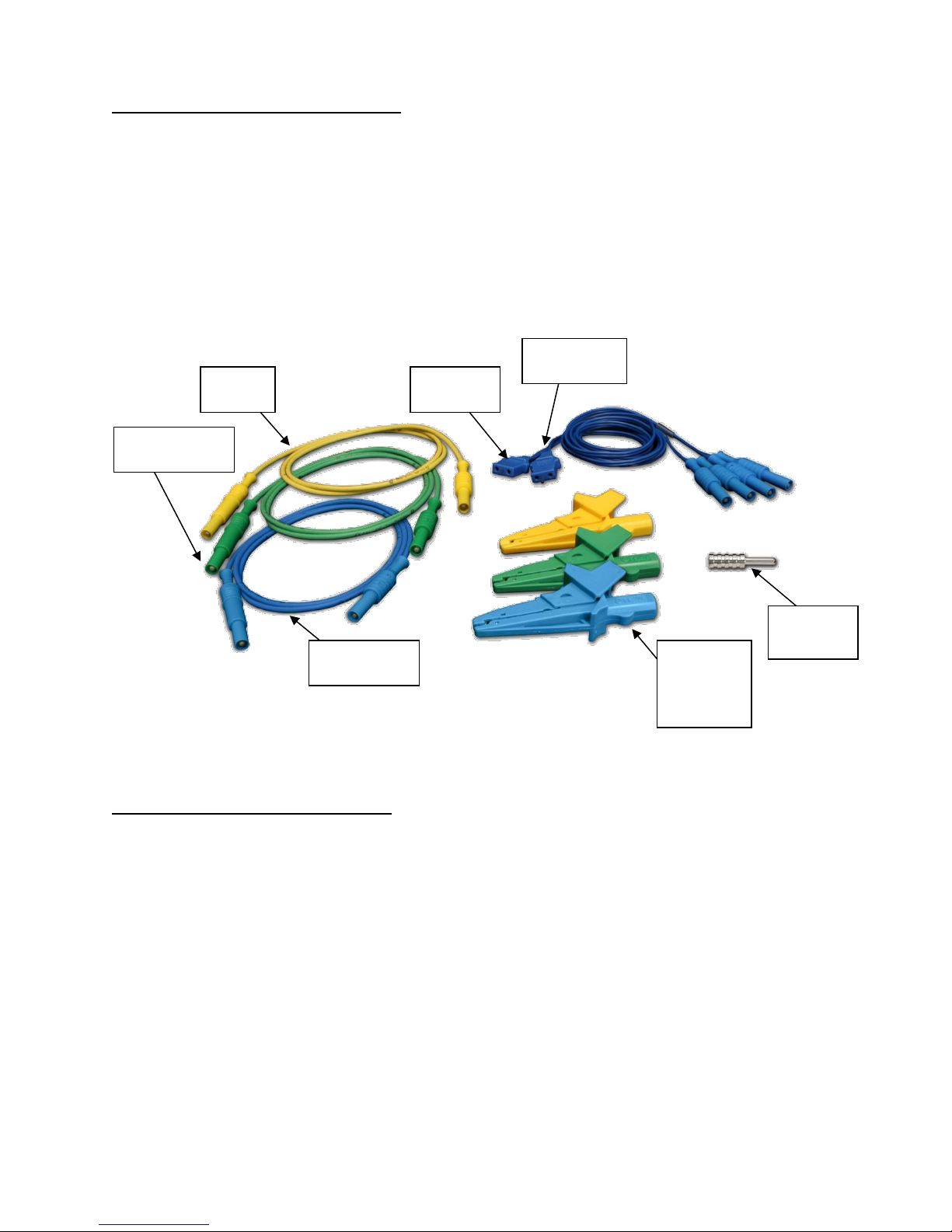
STANDARD ACCESSORIES:
BC20 – 00130 Accessory Kit (Test Leads)
BC20 – 21107 Universal Power Supply
BC20 – 41341 Communications Cable (RS-232)
BC20 – 205XX Standard Power Adapter
(International Options, See Page 138 For Details)
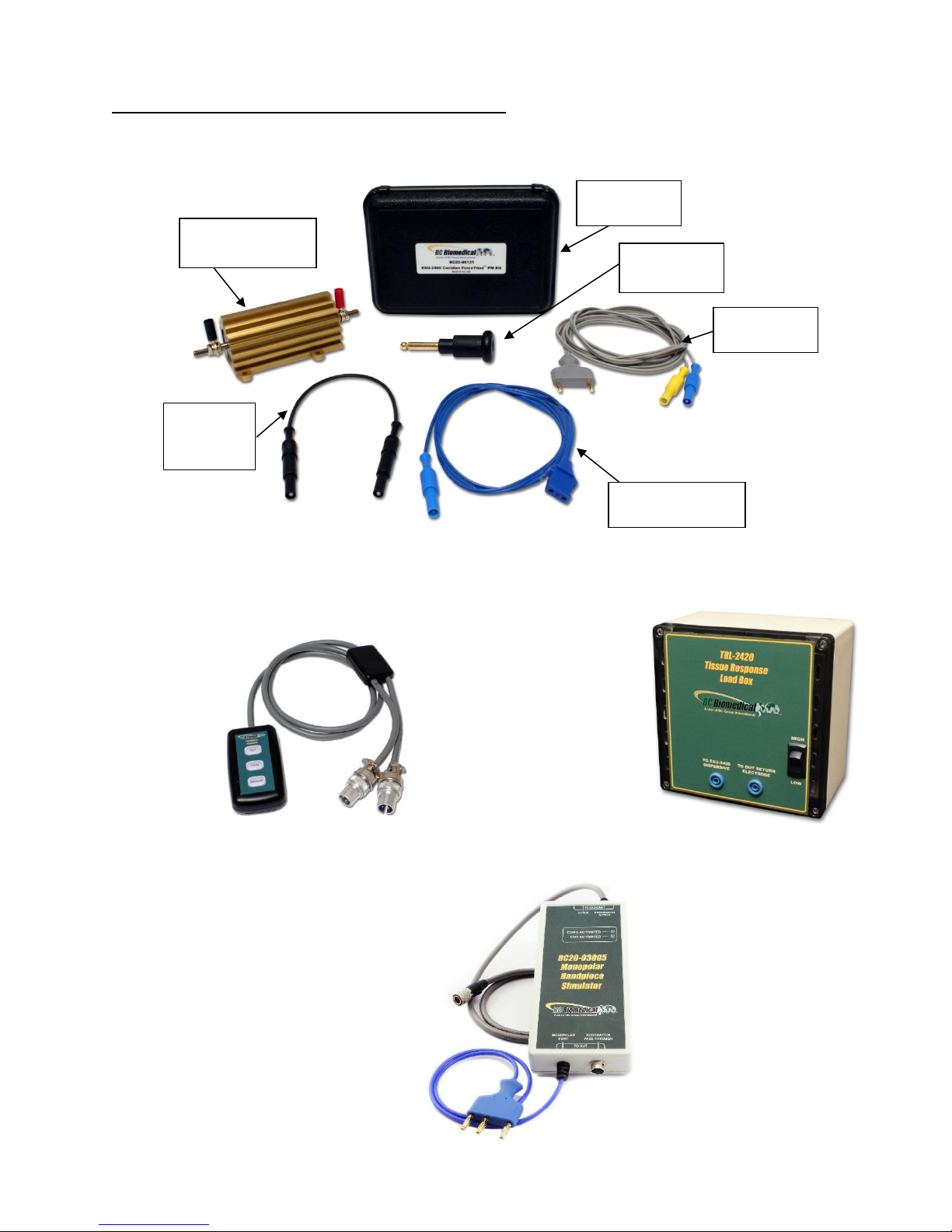
Standard Accessory Kit, BC20-00130:
OPTIONAL ACCESSORIES:
BC20 – 00131 ForceTriad PM Accessory Kit
BC20 – 00132 CONMED PM Kit
BC20 – 00133 CONMED Automation Kit
BC20 – 00140 Replacement packaging
BC20 – 41360 Communications Cable, USB Null Modem
BC20 – 00232 BNC To BNC Cable
BC20 – 03000 Footswitch Cable, Unterminated
BC20 – 03001 Footswitch Cable for Covidien ForceFx
BC20 – 03002 Footswitch Cable for CONMED System 5000
BC20 – 03003 Footswitch Cable for Covidien ForceTriad
BC20 – 03004 Footswitch Simulator for Covidien ForceFx and
ForceTriad, triggers Cut, Coag, Bipolar
Ground
Lug
Active
Lead
CQM
Lead
Banana
Jack
Alligator
Clips
Earth/Ground
Lead
RECQM
Lead
Dispersive
Lead
Page 16

4
BC20 – 03005 Monopolar Hand Switch Simulator
BC20 – 03006 Footswitch Cable for Olympus ESG-100
BC20 – 03007 Footswitch Cable for Olympus ESG-400
TRL – 2420 Tissue Response Load
Page 17
5
OPTIONAL ACCESSORIES (continued):
Optional Accessory Kit, BC20-00131, ForceTriad PM Accessory Kit
BC20-03004
Footswitch Simulator
TRL-2420
Tissue Response Load
BC20-03005
Monopolar Handpiece
Simulator
Autobipolar
Lead
Cross Coupling
Lead
Carrying
Case
UFP Port
Adapter
External Cross
Coupling Load
Cross
Coupling
Lead
Page 18
6
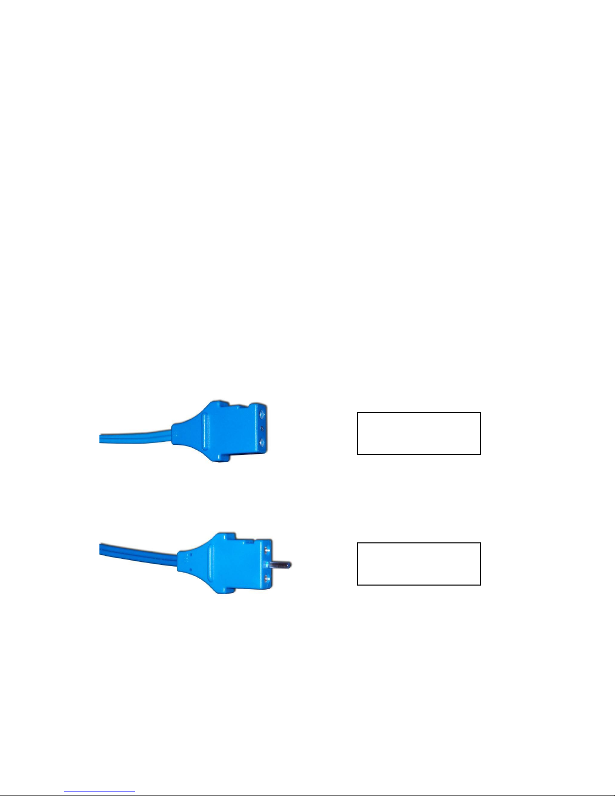
CQM Cable Differences – Two CQM cables are provided in the standard accessory kit.
The only difference between them is that one cable has a small pin and the other does
not. The cable with the pin is used to enable the REM circuitry on the DUT. The cable
without the pin is used to bypass the REM circuit and allow for shorting of the REM leads.
Note that some generators do not allow for the REM circuit to be disabled. For these
generators it does not matter which cable is used.
When using the ESU-2400 CQM test mode, the cable with the pin must be used.
For other modes, the Dispersive ports on the ESU-2400 are shorted together and the
cable without the pin should be used.
Cable Without Pin,
Disabled REM
Cable With Center
Pin, Enables REM
Page 19
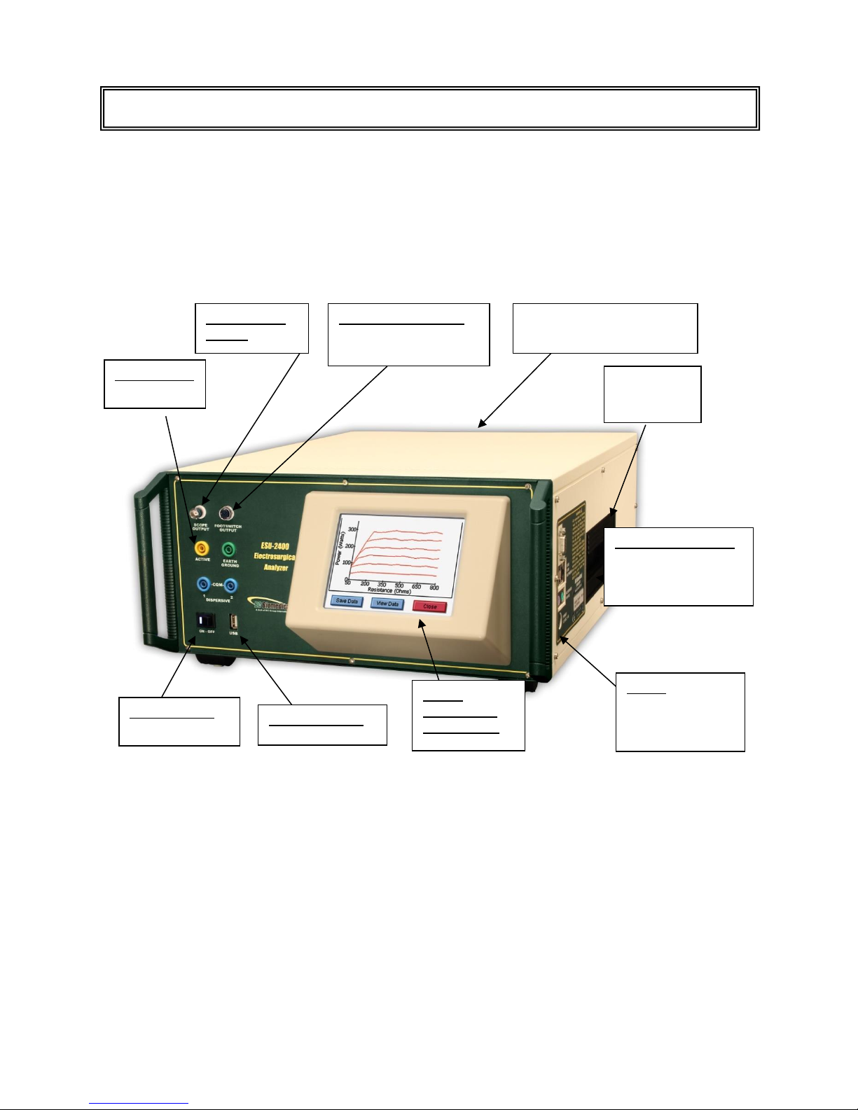
7
This section looks at the layout of the ESU-2400 and gives descriptions of the elements
that are present.
Swivel
Carrying
Handle
Computer Interface
Serial Port
2 USB Ports
10/100 Ethernet
Power
Kycon 3 position
locking
receptacle
QVGA
Display with
touchscreen
Durable Powder-Coated,
Custom Aluminum Case
Front USB Port
Power Switch
Rocker Switch
Oscilloscope
Output
Footswitch Interface
Automated DUT
Activation
Safety Jacks
RF Input
OVERVIEW
Page 20
8
The ESU-2400 Series utilizes an internal current transformer and internal precision load
resistors for simple configuration of typical Electrosurgical Generator testing. Many of the
world’s leading Electrosurgical generator manufacturers utilize this exact same technique
when they test, service and calibrate their generators.
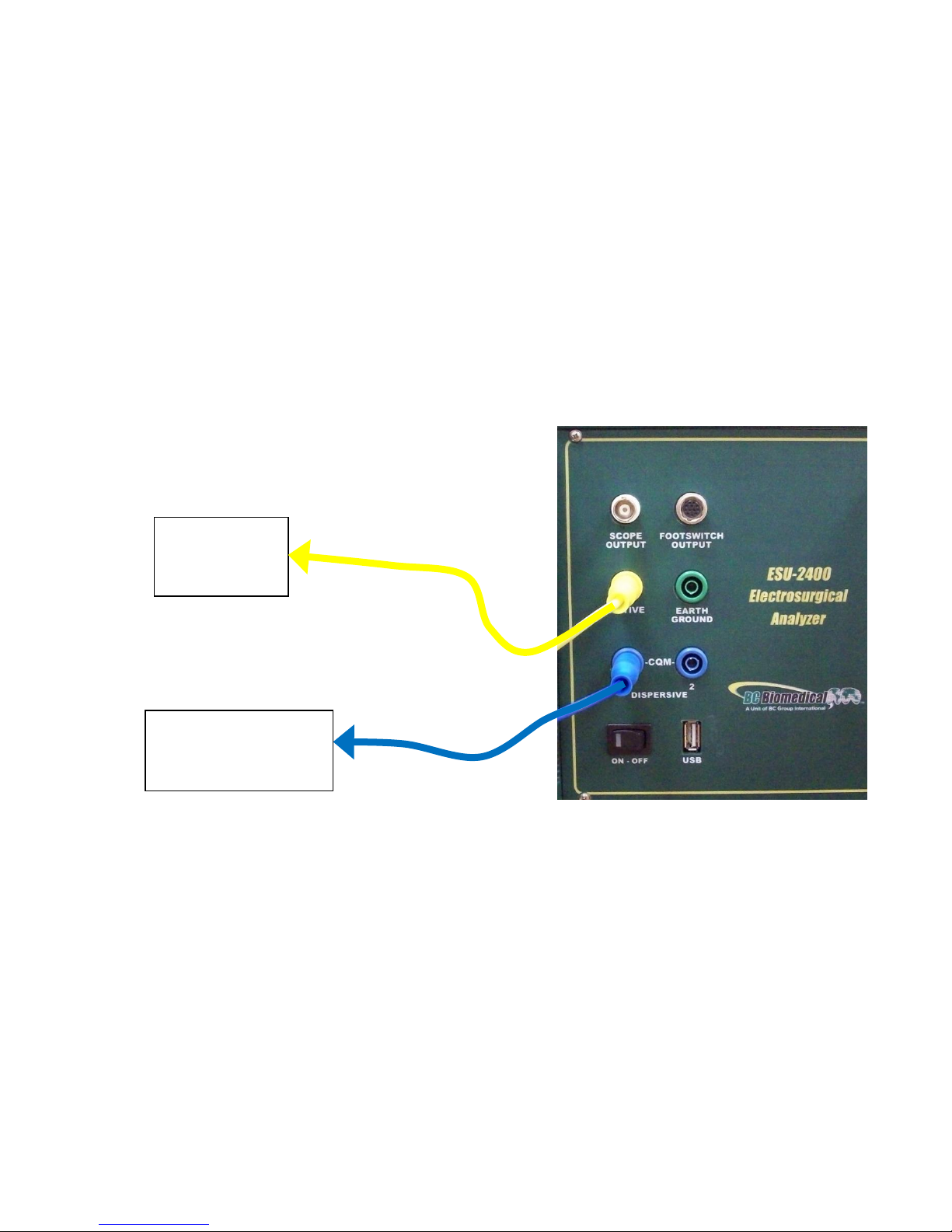
Internal configuration relays allow for simple connections to the DUT. When the Measure
RF Energy, Measure RF Leakage, or REM/ARM/CQM mode is selected from the main
menu, the relays configure the internal connections as required. Shown below are
examples of external connections to the DUT.
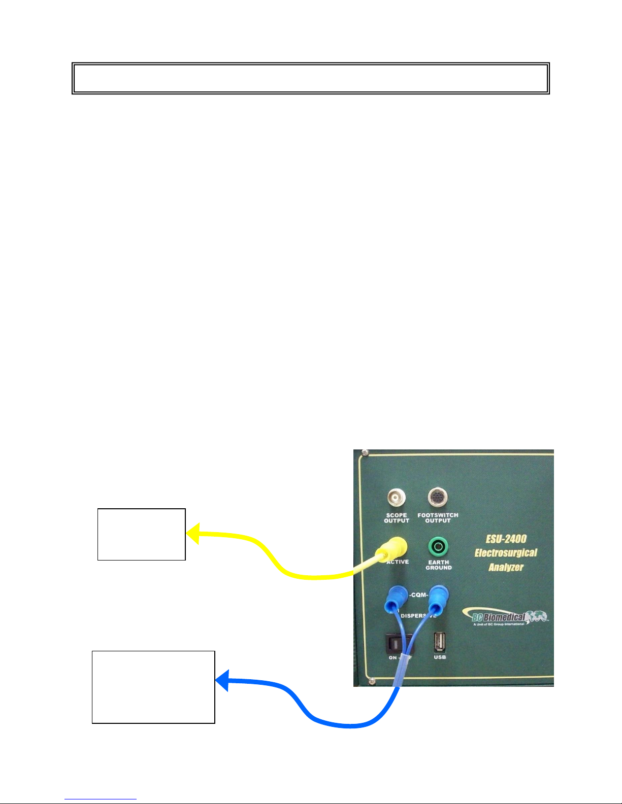
Monopolar:
1. Yellow Active Lead from Active Jack on ESU-2400 to DUT Output.
2. Blue Dispersive Lead from Dispersive Jack on ESU-2400 to DUT Dispersive.
TYPICAL MEASUREMENT CONNECTIONS
ESU (DUT)
Active
Electrode
ESU (DUT)
Patient Return/
Dispersive
Electrode
Page 21
9
Bipolar:
1. Yellow Active Lead from Active Jack on ESU-2400 to DUT Bipolar Output
Electrode #1.
2. Blue Lead from Dispersive1 Jack on ESU-2400 to DUT Bipolar Output
Electrode #2.
ESU (DUT)
Bipolar
Electrode #1
ESU (DUT)
Bipolar
Electrode #2
Page 22
10
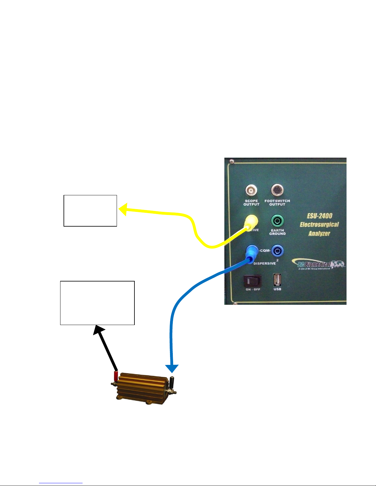
External Loads
Monopolar:
1. Yellow Active Lead from Active Jack on ESU-2400 to DUT Output.
3. Blue Lead from Dispersive 1 Jack on ESU-2400 to External Load.
4. External Load to DUT Dispersive.
ESU (DUT)
Active
Electrode
ESU (DUT)
Patient Return/
Dispersive
Electrode
Page 23
11
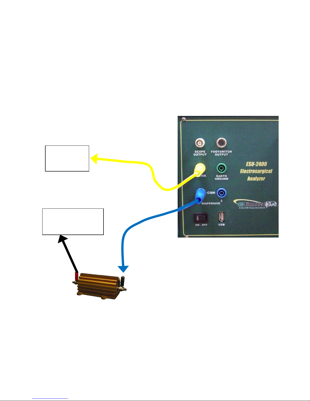
Bipolar
1. Yellow Active Lead from Active Jack on ESU-2400 to DUT Bipolar Output
Electrode #1.
2. Blue Lead from Dispersive 1 Jack on ESU-2400 to External Load.
3. External Load to DUT Bipolar Output Electrode #2.
ESU (DUT)
Bipolar
Electrode #1
ESU (DUT)
Bipolar
Electrode #2
Page 24
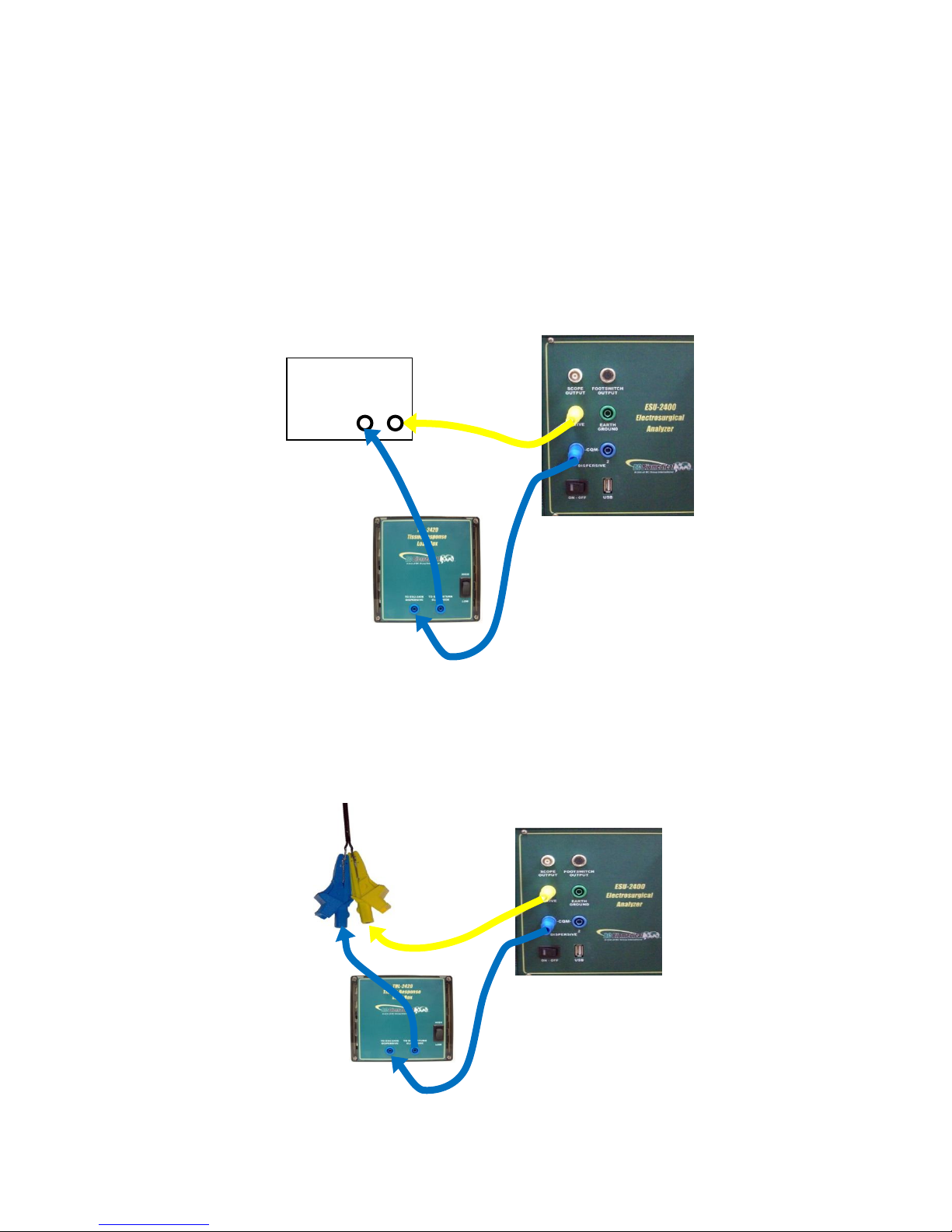
12
Tissue Test – This mode evaluates the tissue response function of the DUT. In this
mode, the ESU-2400 is configured for an external TRL-2420 lamp load. The ESU-2400
is connected in series with the load as shown below. The terminals are labeled Return
and Active for reference only. The DUT Return terminal shown below is typically not the
Patient Return or REM electrode. Refer to the DUT service manual to determine which
DUT ports are used for the tissue response output.
If the output terminals of the DUT are not compatible with the standard ESU-2400 safety
test leads, the alligator clips supplied with the ESU-2400 accessory kit can be used to
connect directly to the electrosurgical instrument as shown in the connection diagram
below.
ESU Generator
(DUT)
Active
Return
Page 25
13
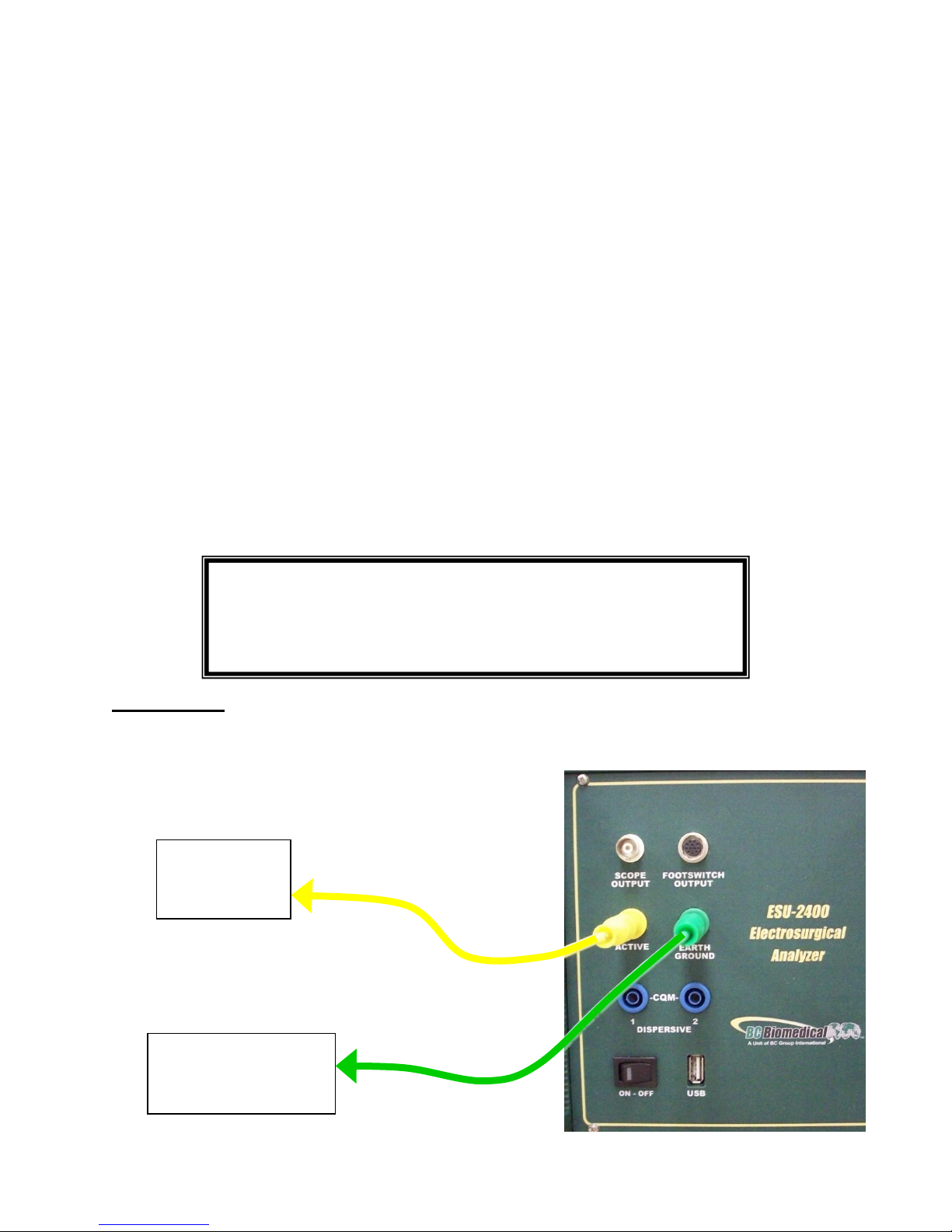
Leakage 1a: This leakage test, specified by the IEC as Active Electrode to Ground, is for
testing the RF leakage to earth ground of an Isolated Output type CF electrosurgical
generator from a single active or dispersive lead. The test complies with IEC 601.2.2,
sec. 19.101b, fig, 104 and sec. 19.102, adopted by ANSI/AAMI HF18-2001. The purpose
of this test is to verify that open circuit RF leakage of the DUT meets or exceeds the IEC
specification. The ESU-2400 internally connects the load to earth ground. An external
ground is also provided at the front panel.
NOTE: DO NOT TEST AN EARTH REFERENCED TYPE BF ELECTROSURGICAL
GENERATOR WITH THIS TEST, THE RESULTING MEASUREMENT WILL BE
ERRONEOUS.
Connections
1. Active Jack on ESU-2400 to DUT Active Output or Bipolar 1.
WARNING – ONE LEAD AT A TIME
Only test one lead of the ESU Generator at a
time, either Active or Dispersive, not both.
ESU (DUT)
Active
Electrode
Earth Ground to
DUT equipotential
jack.
Page 26
14
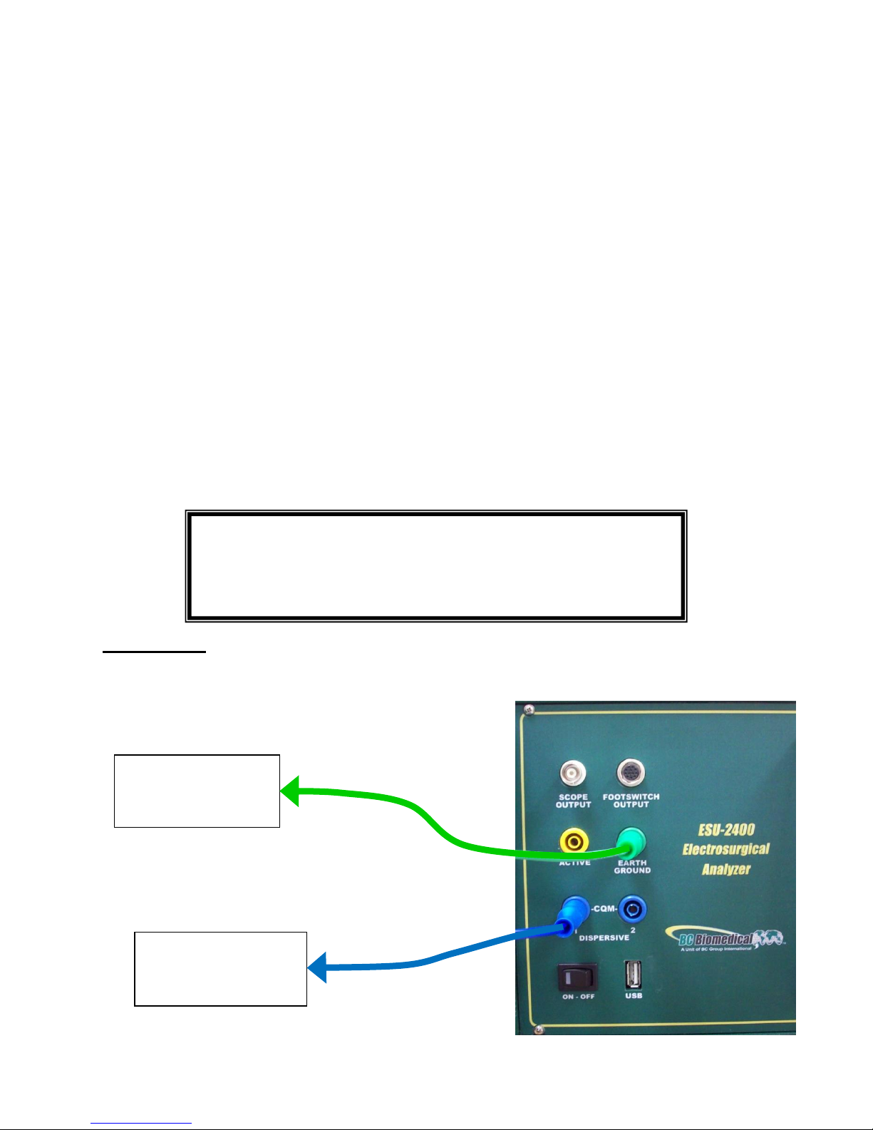
Leakage 1b: This leakage test, specified by the IEC as Dispersive Electrode to Ground,
is for testing the RF leakage to earth ground of an Isolated Output type CF electrosurgical
generator from a single active or dispersive lead. The test complies with IEC 601.2.2,
sec. 19.101b, fig, 104 and sec. 19.102, adopted by ANSI/AAMI HF18-2001. The purpose
of this test is to verify that open circuit RF leakage of the DUT meets or exceeds the IEC
specification. The ESU-2400 internally connects the load to earth ground. An external
ground is also provided at the front panel.
NOTE: DO NOT TEST AN EARTH REFERENCED TYPE BF ELECTROSURGICAL
GENERATOR WITH THIS TEST, THE RESULTING MEASUREMENT WILL BE
ERRONEOUS.
Connections
1. Dispersive 1 Jack on ESU-2400 to DUT Dispersive Output or Bipolar 2.
WARNING – ONE LEAD AT A TIME
Only test one lead of the ESU Generator at a
time, either Active or Dispersive, not both.
Earth Ground to
DUT equipotential
jack
ESU (DUT)
Dispersive
Electrode
Page 27
15
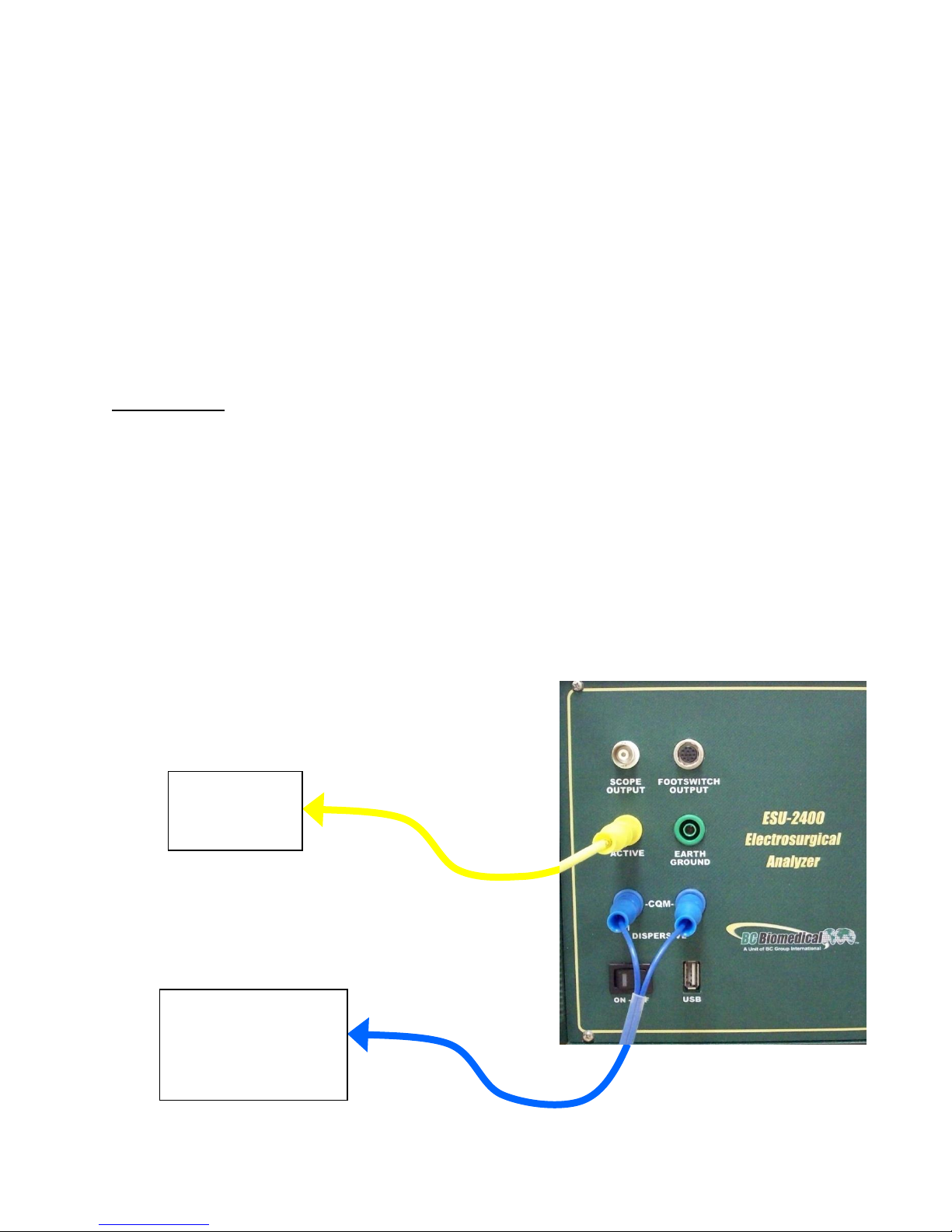
Leakage 2: This leakage test, specified by the IEC as Earth Reference Leakage Type BF
(Load Between Electrodes), is for testing the leakage to earth ground of a Ground
Referenced Output type BF electrosurgical generator from the active output. This test
complies with IEC 601.2.2, sec. 19.101a, test 1, fig. 102, and sec. 19.102, adopted by
ANSI/AAMI HF18-2001. The purpose of this test is to verify that the RF leakage of the
DUT meets or exceeds the IEC specification.
Connections
1. Active Lead from Active Jack on ESU-2400 to DUT Active Output.
2. Dispersive Lead from Dispersive Jack on ESU-2400 to DUT Dispersive.
ESU (DUT)
Active
Electrode
ESU (DUT)
Patient Return/
Dispersive
Electrode
Page 28
16
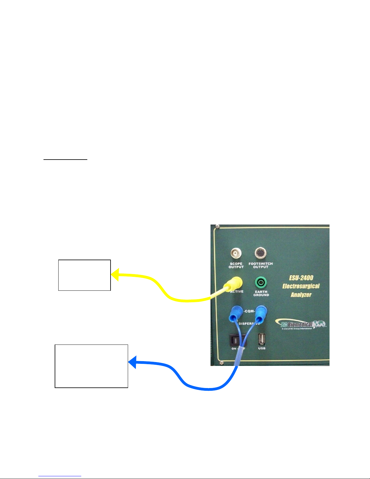
Leakage 3: This leakage test, specified by the IEC as Earth Reference Leakage Type BF
(Load from Active Electrode to Earth) is for testing the leakage to earth ground of a
Ground Referenced Output type BF electrosurgical generator from the active output. This
test complies with IEC 601.2.2, sec. 19.101a, test 2, fig. 102, and sec. 19.102, adopted
by ANSI/AAMI HF18-2001. The purpose of this test is to verify that the RF leakage of the
DUT meets or exceeds the IEC specification.
Connections
1. Active Lead from Active Jack on ESU-2400 to DUT Active Output.
2. Dispersive Lead from Dispersive Jack on ESU-2400 to DUT Dispersive.
ESU (DUT)
Active
Electrode
ESU (DUT)
Patient Return/
Dispersive
Electrode
Page 29
17
This section was written to help you get started with the ESU-2400. Examples are
given for typical configurations of RF Measurement, REM/ARM/CQM testing, Load
Curves and Autosequences. This section will give specific examples of how to
configure the ESU-2400 plus additional modifications that might help fulfill your specific
testing requirements.
Scenario 1 – I need to do a Preventative Maintenance safety check on a Covidien
ForceTriad™ surgical generator.
Solution – The ESU-2400 is capable of automating the ForceTraid™ testing under the
manufacturer’s Preventative Maintenance using the Autosequence feature.
Please see the included ForceTriad™ PM Procedure Using ESU-2400 Autosequence
Manual with your ESU-2400 for detailed instructions. This manual and a tutorial video
can also be found online at http://esu.bcgroupintl.com.
FORCETRIAD™ PREVENTATIVE MAINTENANCE
GETTING STARTED
Page 30
18
Scenario 1 – I need to measure monopolar current with a 500 ohm load. I don’t have a
footswitch cable, so I will trigger the DUT myself.
Solution –
1. Select Measure RF Energy from the main menu.
2. Connect the Active output from the DUT to the Active input on the ESU-2400. If
you are using the cables from the ESU-2400 accessory kit, use the Yellow Lead.
3. Connect the Dispersive or Return port on the DUT to the Dispersive 1 and
Dispersive 2 inputs on the ESU-2400. If you are using the cables from the ESU2400 accessory kit, use the Blue cable without the pin.
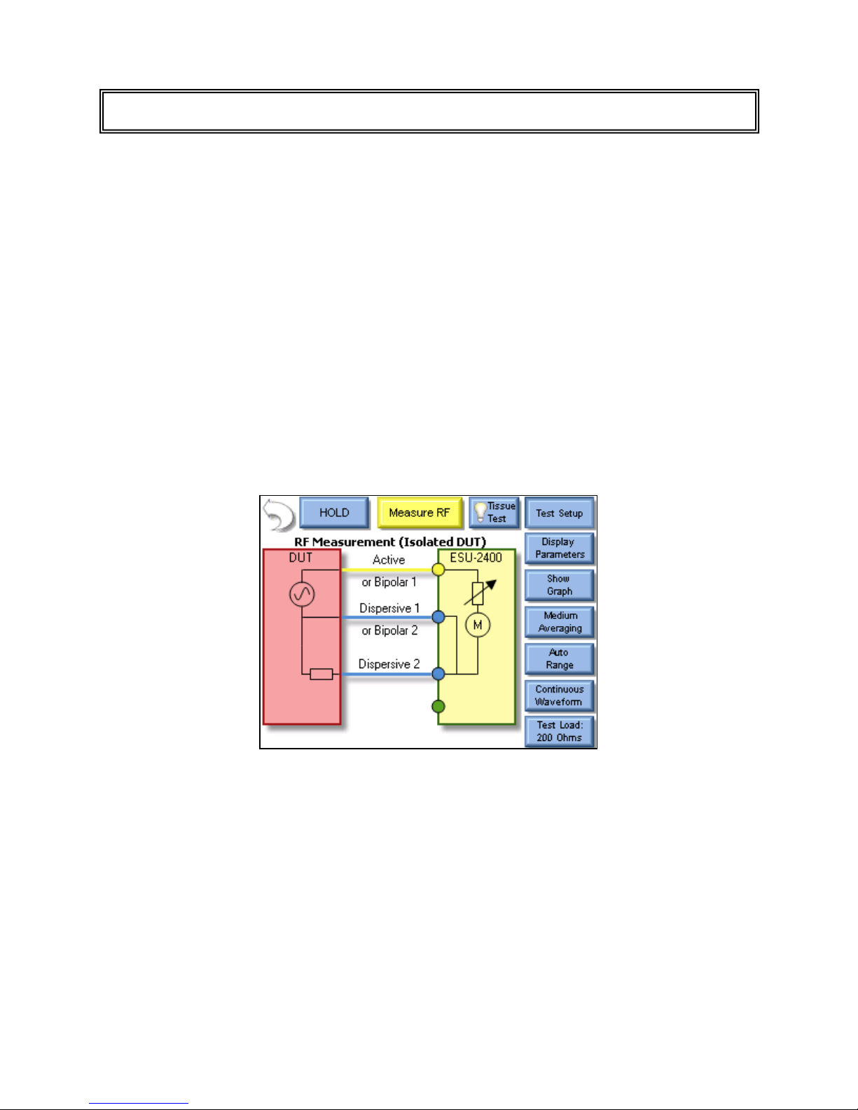
4. Press the Isolated Generator Type button to configure the ESU-2400 for isolated
generator measurements.
NOTE: To see how the ESU-2400 is internally configured, press the Test Setup button. To close
the image, press Test Setup again.
MEASURE RF ENERGY
Page 31

19
5. Press the Test Load button to open the load configuration box. The screen
should look like the following:
NOTE: The ESU-2400 can be configured to use internal loads, external loads, or a combination of
both. First select the Load Mode, then enter the desired internal and external loads. The total load
will automatically be updated. For most testing, the internal loads will be sufficient.
6. Press the Button next to Internal Load and enter 500 in the number pad. The
system should return to the Measure RF screen.
7. Trigger the DUT. The mA measurement will be shown on the ESU-2400 Screen.
NOTE: The displayed measurement can be changed by pressing the mA RMS button. There are
many measurements that can be displayed.
Page 32

20
Scenario 2 – I need to measure mA and Watts of a Bipolar output with a 300 ohm
Load. I want the ESU-2400 to trigger the DUT with the footswitch output.
Solution –
1. Select Measure RF Energy from the main menu.
2. Connect one Bipolar output from the DUT to the Active input on the ESU-2400. If
you are using the cables from the ESU-2400 accessory kit, use the Yellow Lead.
3. Connect the other Bipolar output port from the DUT to the Dispersive 1 input on
the ESU-2400. If you are using the cables from the ESU-2400 accessory kit, use
the Blue cable with banana jacks on each end, not the CQM/RECQM cable.
4. Press the Test Load button to open the load configuration box. The screen
should look like the following:
5. Press the Button next to Internal Load and enter 300 in the number pad. The
load configuration box should automatically close.
Page 33

21
6. Press the Display Parameters button and select Two Readings from the Select
Screen menu.
NOTE: By default mA RMS and Watts RMS are shown when Two Readings are selected. Each
position can display any of the ESU-2400 measurements by pressing the corresponding
measurement button.
Page 34

22
7. Press the Configure Footswitch button to open the Footswitch Setup box.
8. Use the dropdown arrow under Select Output to select the Bipolar output.
9. Use the dropdown arrow under Activation Timeout to select the maximum time
the DUT will be triggered.
NOTE: The footswitch output selection is only valid for footswitch cables that are designed for a
specific DUT, such as the BC20-03001 or BC20-03002. If you are using the unterminated
footswitch cable, BC20-03000, the output selection is dependent on how the cable is wired.
10. Press the footswitch button to trigger the DUT. The mA and Watts
measurements will be shown on the ESU-2400 Screen.
11. You may either wait for the Footswitch Activation Timeout, or press the
Footswitch button again to stop triggering the DUT output.
Page 35

23
Scenario 3 – I need to measure the mA output of a Hyfrecator (ground referenced
generator) with a 100 ohm load. I don’t have a footswitch cable, so I will trigger the
DUT myself.
Solution –
1. Select Measure RF Energy from the main menu.
2. Connect the Active output from the DUT to the Active input on the ESU-2400. If
you are using the cables from the ESU-2400 accessory kit, use the Yellow Lead.
3. Press the Gnd Ref generator type button to configure the ESU-2400 to make a
ground referenced measurement.
NOTE: To see how the ESU-2400 is internally configured, press the Test Setup button. To close
the image, press Test Setup again.
Page 36

24
4. Press the Test Load button to open the load configuration box. The screen
should look like the following:
NOTE: The ESU-2400 can be configured to use internal loads, external loads, or a combination of
both. First select the Load Mode, then enter the desired internal and external loads. The total load
will automatically be updated. For most testing, the internal loads will be sufficient.
5. Press the Button next to Internal Load and enter 100 in the number pad. The
screen should automatically return to the Measure RF screen.
6. Trigger the DUT. The mA measurement will be shown on the ESU-2400 Screen.
NOTE: The displayed measurement can be changed by pressing the mA RMS button. There are
many measurements that can be displayed.
Page 37

25
Scenario 4 (ESU-2400H Model Only) – I need to measure the frequency and mA
output of a generator with a pulsed waveform using a 200 ohm load. I know that the
waveform has a 700 mA pulse but little or no current between pulses. I don’t have a
footswitch cable so I will trigger the DUT myself.
Solution –
1. Select Measure RF Energy from the main menu.
2. Connect the Active output from the DUT to the Active input on the ESU-2400. If
you are using the cables from the ESU-2400 accessory kit, use the Yellow Lead.
3. Connect the Dispersive or Return port on the DUT to the Dispersive 1 and
Dispersive 2 inputs on the ESU-2400. If you are using the cables from the ESU2400 accessory kit, use the Blue cable without the pin.
4. Press the Isolated Generator Type button to configure the ESU-2400 for isolated
generator measurements.
5. Press the Input Mode button, which by default reads “Continuous Waveform”,
and select Pulsed from the dialog options.
Page 38

26
6. This will open the Pulsed Mode Configuration screen. Select Pulsed Mode 1 by
clicking on the mode button or the picture.
7. A threshold should be chosen so that the pulse will be over the threshold but not
too close to the maximum value to account for variations in the waveform. In this
scenario 600mA is sufficient to detect the 700mA waveform. See pg 89 for more
information on choosing a threshold.
8. Press the button next to Threshold 1 and enter 600 mA for the threshold.
9. Click the Accept Changes button to enter your settings and return to the
measurement screen.
10. Press the Display Parameters button and select Two Readings from the Select
Screen menu.
Page 39

27
11. By default mA and Watts are displayed when selecting two readings. Press the
button labeled Watts and then press the button labeled kHz to change the
measurement to frequency.
12. Trigger the DUT. The measurements will be displayed on the ESU-2400.
Page 40

28
Scenario 5 (ESU-2400H Model Only) – I need to measure the load voltage of a
generator that has a pulsed waveform with a long settling time of about 2 seconds. I
don’t have a footswitch cable so I will trigger the DUT myself.
Solution –
1. Select Measure RF Energy from the main menu.
2. Connect the Active output from the DUT to the Active input on the ESU-2400. If
you are using the cables from the ESU-2400 accessory kit, use the Yellow Lead.
3. Connect the Dispersive or Return port on the DUT to the Dispersive 1 and
Dispersive 2 inputs on the ESU-2400. If you are using the cables from the ESU2400 accessory kit, use the Blue cable without the pin.
4. Press the Isolated Generator Type button to configure the ESU-2400 for isolated
generator measurements.
5. Press the Input Mode button, which by default reads “Continuous Waveform”,
and select Delayed from the dialog options.
NOTE: Delayed Mode is designed for use with pulsed waveforms only.
Page 41

29
6. This will open the Delayed Mode Configuration screen. Press the button below
“Delay Time” and enter 2000 ms as the delay.
7. Click the Accept Changes button to enter your settings and return to the
measurement screen.
Page 42

30
8. By default mA is displayed. Press the button labeled mA and then press the
button labeled V Load to change the measurement to load voltage.
9. Trigger the DUT. The measurements will be displayed on the ESU-2400H.
Page 43

31
Leakage Test 1a – I need to measure the leakage current from an Active lead to
ground of a type CF ESU generator.
Solution –
1. Select Measure RF Leakage from the main menu.
2. If the Leakage selection at the top of the screen does not show Leakage 1a,
press the button and select Leakage 1a from the test mode menu.
3. Connect the Active output from the DUT to the Active input on the ESU-2400. If
you are using the cables from the ESU-2400 accessory kit, use the Yellow Lead.
4. Connect earth ground port on the ESU-2400 to the ground lug on the back of the
DUT. If you are using the cables from the ESU-2400 accessory kit, use the
green cable and green alligator clip.
NOTE: To see how the ESU-2400 is internally configured, press the Test Setup button. To close
the image, press Test Setup again.
MEASURE RF LEAKAGE
Page 44

32
5. Trigger the DUT. The ESU-2400 will show the mA RMS measurement in the
display.
Page 45

33
Leakage Test 1b – I need to measure the leakage current from the dispersive (REM)
port to ground.
Solution –
1. Select Measure RF Leakage from the main menu.
2. If the Leakage selection at the top of the screen does not show Leakage 1b,
press the button and select Leakage 1b from the test mode menu.
3. Connect the Dispersive output from the DUT to the Dispersive inputs on the
ESU-2400. If you are using the cables from the ESU-2400 accessory kit, use the
Blue cable without the clear pin.
4. Connect earth ground port on the ESU-2400 to the ground lug on the back of the
DUT. If you are using the cables from the ESU-2400 accessory kit, use the
green cable and green alligator clip.
NOTE: To see how the ESU-2400 is internally configured, press the Test Setup button. To close
the image, press Test Setup again.
Page 46

34
5. Trigger the DUT. The ESU-2400 will show the mA RMS measurement in the
display.
Page 47

35
Leakage Test 2– I need to measure the leakage current from the dispersive (REM) port
to ground. I need to have a 200 ohm load from Active to Dispersive during the test.
Solution –
1. Select Measure RF Leakage from the main menu.
2. If the Leakage selection at the top of the screen does not show Leakage 2, press
the button and select Leakage 2 from the test mode menu.
3. Connect the Active output from the DUT to the Active input on the ESU-2400. If
you are using the cables from the ESU-2400 accessory kit, use the Yellow Lead.
4. Connect the Dispersive output from the DUT to the Dispersive inputs on the
ESU-2400. If you are using the cables from the ESU-2400 accessory kit, use the
Blue cable without the clear pin.
5. Connect earth ground port on the ESU-2400 to the ground lug on the back of the
DUT. If you are using the cables from the ESU-2400 accessory kit, use the
green cable and green alligator clip.
NOTE: To see how the ESU-2400 is internally configured, press the Test Setup button. To close
the image, press Test Setup again.
Page 48

36
6. Trigger the DUT. The ESU-2400 will show the mA RMS measurement in the
display.
Page 49

37
Leakage Test 3 – I need to measure the leakage current from the dispersive (REM)
port to ground. I need to have a 200 ohm load from Active to Ground during the test.
Solution –
1. Select Measure RF Leakage from the main menu.
2. If the Leakage selection at the top of the screen does not show Leakage 3, press
the button and select Leakage 3 from the test mode menu.
3. Connect the Active output from the DUT to the Active input on the ESU-2400. If
you are using the cables from the ESU-2400 accessory kit, use the Yellow Lead.
4. Connect the Dispersive output from the DUT to the Dispersive inputs on the
ESU-2400. If you are using the cables from the ESU-2400 accessory kit, use the
Blue cable without the clear pin.
5. Connect earth ground port on the ESU-2400 to the ground lug on the back of the
DUT. If you are using the cables from the ESU-2400 accessory kit, use the
green cable and green alligator clip.
NOTE: To see how the ESU-2400 is internally configured, press the Test Setup button. To close
the image, press Test Setup again.
Page 50

38
6. Trigger the DUT. The ESU-2400 will show the mA RMS measurement in the
display.
Page 51

39
Scenario 1 – I need to test the REM function on my generator. The service manual
says that the REM alarm should be Normal at 35 ohms.
Solution –
1. Select REM/ARM/CQM from the main menu.
2. Press the CQM Resistance button and enter 35 in the number pad. The screen
should look like the following:
3. Connect the Dispersive output from the DUT to the Dispersive inputs on the
ESU-2400. If you are using the cables from the ESU-2400 accessory kit, use the
Blue cable with the center pin.
4. The DUT REM state should be Normal.
REM/ARM/CQM TEST
Page 52

40
Scenario 2 – I need to test the REM function on my generator. The service manual
says that the REM alarm should occur if the resistance increases by 40%.
Solution –
1. Select REM/ARM/CQM from the main menu.
2. Press the CQM Resistance button and enter a resistance that should result in a
normal CQM state, in this example we will use 50 ohms.
3. Press the Change By Percent button and enter 40 in the number pad. The
screen should look like the following:
4. Connect the Dispersive output from the DUT to the Dispersive inputs on the
ESU-2400. If you are using the cables from the ESU-2400 accessory kit, use the
Blue cable with the center pin.
5. The DUT REM state should be Normal.
6. Press the Up arrow under the Change By Percent heading. The resistance will
change to 70 ohms and the DUT should indicate a REM alarm.
Page 53

41
Load Curve Scenario 1 – I need to run a bipolar load curve at 60 Watts with loads from
100 to 1000 ohms, measuring every 100 ohms. I am testing a ForceFx generator and
want the ESU-2400 to automatically configure and trigger the DUT.
Solution –
1. Select Load Curves from the main menu.
2. Select Configure Load Curve from the Load Curve Menu.
3. Press The Setup Loads tab at the top of the screen to configure the Loads
4. Press the Load resistance setting for the First Load and enter 100 in the number
pad.
5. Press the Load resistance setting for the Last Load and enter 1000 in the number
pad.
6. Press the resistance setting in the Step Loads By option and enter 100 in the
number pad. The screen should now look like the following:
LOAD CURVES
Page 54

42
7. Press the Setup Power tab at the top of the screen to configure the power setting
for the test.
8. Select the Single Power Level tab to configure the test for one power setting.
9. Press the DUT Power setting button and enter 60 in the number pad. The screen
should look like the following:
10. Press the DUT tab at the top of the screen to configure the settings for the DUT
trigger.
11. Select the ESU-2400 option for DUT activation. This will enable features for
configuring the DUT setup. The screen should look like the following:
12. For the DUT setup press the dropdown arrow next to Manual Setup to select Setup
By Model.
13. Use the dropdown arrow to set the DUT Output to Bipolar.
Page 55

43
14. Use the dropdown arrow to set the DUT mode to the desired bipolar output mode.
The screen should now look like the following:
15. Connect the ESU-2400 to the DUT. Connect the Yellow cable from the Active port
on the ESU-2400 to one of the Bipolar outputs on the DUT. Connect the Green
cable from the Dispersive 1 port of the ESU-2400 to the other Bipolar output on
the DUT.
16. Connect the RS-232 cable from the ESU-2400 serial port to the DUT serial port.
17. Connect the BC20-03001 footswitch cable from the DUT to the ESU-2400.
18. Press Save configuration on the ESU-2400 to save the Load Curve settings to a
file for future use, or Press Start Load Curve to begin the test. The DUT power
level and output mode will automatically be configured through the RS-232 port.
Page 56

44
Load Curve Scenario 2 – I need to run a pure cut 300 Watt load curve, but there isn’t a
footswitch cable available for my DUT. I need to test my DUT at 50, 300, 500, 800, and
1500 ohms.
Solution –
1. Select Load Curves from the main menu.
2. Select Configure Load Curve from the Load Curve Menu.
3. Press The Setup Loads tab at the top of the screen to configure the Loads
4. Select the List Based Loads option to configure the list of loads to be used for the
test.
5. Press Clear List to remove all of the previous settings from the list of loads to be
used.
6. Press the Add Load button and enter 50 in the number pad.
7. Press the Add Load button again and enter the values for the other loads to be
used; 300, 500, 800, 1500. The loads do not need to be entered in sequence, they
will automatically be sorted as they are entered. If an incorrect load is accidentally
entered, select the incorrect load by pressing on it and then press the Delete Load
button, it will be removed from the list. The screen should now look like the
following:
Page 57

45
8. Press the Setup Power tab at the top of the screen to configure the power setting
for the test.
9. Select the Single Power Level tab to configure the test for one power setting.
10. Press the DUT Power setting button and enter 300 in the number pad. The screen
should look like the following:
11. Press the DUT tab at the top of the screen to configure the settings for the DUT
trigger.
12. Select the Operator option for DUT activation.
Page 58

46
13. Connect the ESU-2400 to the DUT. Connect the Yellow cable from the Active port
on the ESU-2400 to active output on the DUT. Connect the Blue cable from the
Dispersive ports of the ESU-2400 to the return on the DUT.
14. Press Save Configuration on the ESU-2400 to save the Load Curve settings to a
file for future use, or Press Start Load Curve to begin the test. You will be prompted
when to start and stop triggering the generator.
Page 59

47
RF Measure: I need to configure an Autosequence step to take an RF current
measurement with a 200 ohm load. My measurement tolerance is 315mA, ±25mA.
Solution –
1. From the Autosequence menu, select Create New Sequence. Then press Add
Step.
2. Select the desired location for the new step and press OK.
3. The new step will always default to an instruction type step. Select the RF Energy
/ Leakage option button near the bottom of the screen.
4. Press the title Text box to change the step title as desired. You will need to use
an external keyboard for this.
5. Press the Instructions to Operator text box to enter any instructions that the user
might need to perform at this step of the autosequence.
6. Press the Meter Setup button to configure the measurement mode and tolerance.
AUTOSEQUENCES
Page 60

48
7. Press the Test Load button to open the Load Configuration menu.
8. Press the Internal Load value button to change the internal load to 200 ohms. By
default, the user will not be able to change the load resistance once the test is
running. If you would like for the operator to be able to change the load, check the
box next to Allow Operator to modify load.
9. Press the Test Load button again or the Red X button to close the Load
Configuration menu.
10. Press the Tolerance option button at the bottom of the screen to configure the
tolerance for the RF measurement.
11. The DUT output mode and output type and power setting can be selected at the
top of the screen. These are informational only and do not have any effect on the
test or measurement.
12. Use the dropdown arrow under Expected Reading to change the tolerance mode
to Equal to (Value).
13. Press the number button to the right of the expected reading and enter 315 in the
number pad. Additionally, if the desired reading were watts or any other
measurement taken by the ESU-2400, the red button to the right of the expected
reading can be pressed to change the measurement being tested.
14. Press the number button for High Limit and set the value to 25 with the number
pad.
15. Press the number button for Low limit and set the value to 25 with the number pad.
Page 61

49
16. Additionally, if you would like to allow the user to override the automated limit
testing, you can check the box next to Allow operator to select Pass/Fail status.
17. The screen should look like the following; the configuration is complete for this
step. Press Back to Step Edit and then Done to return to the Autosequence
Summary screen.
Page 62

50
Load Curve– I need to run a pure cut 300 Watt load curve, and there isn’t a footswitch
cable available for my DUT. I need to take 10 measurements with loads from 50 to 5000
ohms.
Solution –
1. From the Autosequence menu, select Add Step.
2. Select the desired location for the new step and press OK.
3. The new step will always default to an instruction type step. Select the Load Curve
option button near the bottom of the screen.
4. Press the Title text box to change the step title as desired. You will need to use
an external keyboard for this.
5. Press the Instructions to Operator text box to enter any instructions that the user
might need to perform at this step of the autosequence.
6. Press the Meter Setup button to configure the load curve.
7. Press The Setup Loads tab at the top of the screen to configure the Loads
Page 63

51
8. Press the Load resistance setting for the First Load and enter 50 in the number
pad.
9. Press the Load resistance setting for the Last Load and enter 5000 in the number
pad.
10. Press the step setting in the Total Steps in Test option and enter 10 in the number
pad. The screen should now look like the following:
11. Press the Setup Power tab at the top of the screen to configure the power setting
for the test.
12. Select the Single Power Level tab to configure the test for one power setting.
13. Press the DUT Power setting button and enter 300 in the number pad. The screen
should look like the following:
14. The configuration is complete for this step. Press Back to Step Edit and then Done
to return to the Autosequence Summary screen.
Page 64

52
Auto CQM– I need to test the CQM input on my generator. My generator service manual
says to increase the CQM resistance starting at 120 ohms until the CQM alarm occurs.
The CQM trip resistance should be 135 ohms +/- 5 ohms.
Solution –
1. From the Autosequence menu, select Add Step.
2. Select the desired location for the new step and press OK.
3. The new step will always default to an instruction type step. Select the
REM/ARM/CQM option button near the bottom of the screen.
4. Press the Title text box to change the step title as desired. You will need to use
an external keyboard for this.
5. Press the Instructions to Operator text box to enter any instructions that the user
might need to perform at this step of the autosequence.
6. Press the Meter Setup button to configure the settings for the REM test.
7. Select the Auto CQM option at the top of the screen.
Page 65

53
8. Select the Step Values tab to configure the CQM resistance to be used. The
screen should look like the following:
9. Press the First Load button and enter 120 in the number pad.
10. Press the Last Load button and enter 145 ohms.
11. Press the Step Loads By button and enter 1 in the number pad.
12. Select the option button for Stop when CQM alarm occurs.
13. Press the Set Tolerance button to configure the Pass/Fail limits for the test. Since
the requirement is to alarm at 135 ± 5 ohms, set the CQM Trip point for 135 ohms.
14. Press the Trip Upper limit button and enter 140 in the number pad.
15. Press the Trip Lower limit button and enter 130 ohms in the number pad. The
screen should look like the following:
16. Press the OK button to close the validation requirements menu.
17. The configuration is complete for this step. Press Back to Step Edit and then Done
to return to the Autosequence Summary screen.
Page 66

54
The ESU-2400 boots to the main screen by default. The power up screen can be changed
in the System Setup screen. The main screen provides a quick way to select the desired
operating mode.
Autosequences
This mode provides for automated DUT testing. Autosequences can consist of any
combination of user instructions, RF measurements, Load Curves, or CQM tests.
Autosequences can be edited, loaded, and saved to either on board memory or external
USB drives.
Measure RF Energy
This mode provides for RF measurements. The user can configure the ESU-2400 for the
desired RF measurement including Pulsed/Continuous waveform measurement, load
setting, etc.
MAIN SCREEN
Page 67

55
Power Load Curves
This mode provides for automated load curve testing of the DUT. Load curves can be
configured for multiple load values and power levels.
REM/ARM/CQM
This mode allows the user to test the REM/ARM/CQM function of the DUT. The
resistance can be manually entered, adjusted by a specific resistance, or adjusted by a
percent of resistance. This mode also has the ability to set the CQM load to an open
circuit.
Measure RF Leakage
This mode provides for RF Leakage measurements. The user can configure the ESU2400 for the desired RF Leakage measurement including Pulsed/Continuous waveform
measurement, load setting, etc. All switching for the leakage modes is performed by
internal relays.
System Tools
This mode provides for configuration of the ESU-2400. In this mode the user can calibrate
the touchscreen, update the system firmware, and adjust settings such as filter rate and
system volume.
Page 68

56
System Information
The system information screen is shown by pressing the ESU-2400 title bar on the main
screen. This window provides the basic information about the system including software
versions and calibration due date.
To exit the system information screen, simply press anywhere on the screen.
Page 69

57
The autosequence is a programmable procedure for performing testing on a generator.
The autosequence can consist of any combination of user instructions, RF
measurements, Load Curves, or CQM tests. Once an autosequence is created, it can be
saved as a secure sequence, which cannot be modified. The following image shows the
main autosequence menu, where the user can load an autosequence, begin a ForceTriad
PM, view previously saved test results, or create new autosequence.
When selecting an autosequence, the user has the option of opening an Autosequence
Setup file (*.seq) or a Secure Autosequence (*.ssq) by selecting the filter type in the File
Open dialog box (see page 126). The Secure Sequence cannot be modified by the user.
AUTOSEQUENCES
Page 70

58
The following screen is shown after opening an autosequence setup file.
When a step is selected, it is highlighted in blue and expanded to show the step details.
When a step is not selected, the background is white and only the essential details of the
step are shown. The following buttons are available in this screen.
New – This button will create a new autosequence.
Open – This button will show the file open dialog box that will open an existing
autosequence.
Save – This button will show the file save dialog box. When saving the autosequence,
the file Filter can be used to select whether the file is to be a standard Autosequence
Setup file (*.seq) or Secure Sequence file (*.ssq) or as a PDF (*.pdf). Once a file is saved
as a secure sequence it cannot be modified.
Print – This button will display the print menu.
Start Test – This button starts the displayed autosequence.
Page 71

59
Add Step – This button will show the add step dialog box, shown below. To add a step
to the autosequence, select where to add the step and then press OK.
Delete Step – This button will delete the selected step from the autosequence.
Copy Step – This button will copy the selected step. When copying a step the user has
the option of where to place the new step.
Page 72

60
Edit Step – This button will show the edit step window, shown below.
Each step has a field for the step title and instructions to the user. These fields must be
entered using an external keyboard or remotely with a PC. Each step can be configured
as an Instruction Only, RF Energy / Leakage, Load Curve, or REM/ARM/CQM step by
selecting the appropriate option button at the bottom of the step edit screen.
Page 73

61
DUT Setup
For RF Energy / Leakage and Load Curve steps, the user needs to configure how the
DUT will be activated. For these measurements, the DUT can be activated by the
Operator or the ESU-2400 as shown below. When Operator is selected, the user will be
prompted when to activate or deactivate the ESU.
Auto Advance on Pass – This setting allows for automatically stepping through the
autosequence if a measurement passes the tolerance limits that are configured for the
selected step.
Auto Capture – When enabled, this setting will automatically capture and validate the
DUT output when the current step is reached during the autosequence. If unchecked,
the autosequence will show instructions to the user and the user must manually select
the meter display and capture an RF measurement.
Page 74

62
When ESU-2400 is selected as the trigger source, the activation can be setup manually
or by DUT manufacturer and model. For Manual Setup, the user selects the desired
footswitch output to be used.
If RS-232 is enabled, the user also selects the baud rate and enters commands to be
used for DUT setup and control. When entering commands, use “%P” to represent the
power level. In the example below, the ESU-2400 would send the command “:FTP300”
when the autosequence power level is set to 300 watts.
When the DUT Setup is set to Setup by Model, the user selects the DUT manufacturer
and model as well as the desired output mode. The ESU-2400 handles all of the RS-232
and footswitch output setup.
Page 75

63
RF Energy / Leakage Step – All of the options in the standard RF measurement and
leakage modes are available in the RF Energy / Leakage step configuration.
The user must configure both the ESU-2400 meter as well as the measurement tolerance.
To setup the tolerance, select the Tolerance option button at the bottom of the screen.
Page 76

64
DUT Output Mode – This setting is for display only, to identify to the user the output
mode used.
DUT Output Type – This setting is for display only, to identify the type of output to be
measured.
DUT Power Setting – This setting represents what the DUT should be set to for the
current step.
Expected Reading – This sets how the ESU-2400 determines whether a measurement
passes or fails. Available settings are Equal To (%), Less Than, Greater Than, or Equal
To (Value).
Measurement Units – The user can press the red units button to select what is to be
measured for the current step. Available measurements can be found in the Measure RF
Energy chapter, page 79.
High / Low Limit – These settings determine the limits of the measurement. If Expected
Reading is set to “Equal To (%)”, the limits will be based on a percentage of the expected
reading. If the Expected Reading is set to “Equal To (Value)”, the limits will be based on
a measurement offset from the expected reading. The numbers in parenthesis below the
measurement units display the reading limits based on expected value settings and
High/Low Limits.
Allow Operator to Select Pass/Fail – The tolerances configured on this screen will
determine the pass or fail status of the captured measurement during the autosequence.
In some cases, it may be useful to allow the user to select the pass/fail status of a
particular measurement. If this box is unchecked, the operator will not be allowed to
modify the pass/fail status of the measurement.
Page 77

65
Load Curve Step – All of the options in the standard load curve are available to the load
curve step configuration.
The tabs across the top of the screen allow the user to configure the Loads, Power
settings to be used, and the Meter configuration for the Load Curve.
Setup Loads Tab – The loads can be configured as either a step based load change or
a list based load change. For the step based loads, the user enters the first load to be
used and the last load to be used. Then the ESU-2400 steps the loads by either a fixed
resistance or by a calculated amount to achieve a fixed number of steps for the test. In
the previous picture, the load curve would start at 50 ohms, and increment the load by 35
ohms
2050750
to provide 20 total steps in the test.
Page 78

66
For list based loads, the following screen is shown, allowing the user to select specific
resistances to be used for the test.
The load configuration list can be saved to a file or loaded from a previously saved list.
The loads are automatically sorted by value as they are added to the list.
Page 79

67
Single Power Level Tab – For the load curve power configuration, the user can set the
ESU-2400 to run the load curve at a single power level or multiple power levels. The
following screen shows the configuration for a single power level.
By pressing on the power setting, the user will be able to enter the desired power level
for the load curve test.
Page 80

68
Multiple Power Levels Tab – When using multiple power levels, the configuration
options are similar to the Load config. The user can select either step based power levels
based on a fixed change in watts or based on the number of desired steps in the test.
For list based power levels, the user can enter any combination of power settings to use
for the load curve, as shown below. The power configuration list can be saved to a file or
loaded from a previously saved list. The power settings are automatically sorted by value
as they are added to the list.
Page 81

69
Setup Meter Tab – The measurement mode for the load curve can be configured in the
Setup Meter Tab. This screen allows for the selection of the Input Range, Input Mode,
and Averaging Rate. These settings are adjustable to match the waveform or device
being tested. For the ESU-2400 model analyzer the load curve will always display
measured power in Watts. With the model ESU-2400H analyzer the load curve can be
configured to measure specific units.
ESU-2400 Model ESU-2400H Model
For more information on measurement modes, refer to the RF Measurement chapter of
the manual on page 79.
Page 82

70
Manual CQM Step – CQM autosequence steps can be configured as manual or
automatic tests. For manual CQM autosequence steps, the user configures the initial
CQM resistance and selects whether the operator will be allowed to modify the CQM
resistance. When the test is running, the operator will need to determine whether the
CQM test passes or fails.
Page 83

71
Auto CQM Step – Auto CQM steps allow for greater automation of the autosequence.
Auto CQM steps can be configured as a single resistance test point or as an automatic
sweep of CQM resistances where the CQM status is tested for normal or alarm conditions.
Auto Advance on Pass – This setting allows for automatically stepping through the
autosequence if the CQM status matches the expected setting.
Auto Start CQM Test– When this setting is enabled the ESU-2400 will automatically
trigger the CQM state evaluation to determine if the step passes or fails. If this option is
disabled, the operator will have to trigger the CQM test.
Single Value Tab – The single Value Auto CQM step (shown above) will apply a single
resistance to the DUT CQM circuit and determine whether the step passes or fails based
on the expected status.
Page 84

72
Step Values Tab – This tab allows the user to configure a series of CQM resistances to
be stepped through. The CQM resistance can be configured to step by a fixed resistance
amount or by a fixed number of steps across a range or resistances. At each step, the
DUT CQM state is evaluated. The test can be configured to stop when either an alarm
or normal CQM state occurs.
The Set Tolerance button is used to determine the pass / fail parameters. The CQM
resistance will be stepped until the CQM state is either normal or alarm as programmed
in the step. This point is called the trip resistance. The tolerance configuration allows the
user to configure the trip points that result in a pass or fail status for the test.
Page 85

73
List Values Tab – This allows the user to configure a list of CQM resistances that are
used in the test. During the test the CQM resistance will be sequentially set to the values
shown in the CQM resistance list. The step can be configured to stop when the CQM
state is either alarm or normal.
The Set Tolerance button is used to determine the pass / fail parameters. The CQM
resistance will be stepped until the CQM state is either normal or alarm as programmed
in the step. This point is called the trip resistance. The tolerance configuration allows the
user to configure the trip points that result in a pass or fail status for the test.
Page 86

74
Running the Autosequence:
When an autosequence is started, the user is first prompted to enter information about
the DUT. The data can be entered by pressing on one of the fields and entering the
information from the onscreen keyboard, external keyboard, or barcode scanner.
Instruction Only Steps – These steps will display the instructions that the user is
supposed to follow before proceeding to the next step. Once the instructions have been
performed, the status must be updated to identify if the step passed or failed. Notes can
be added by pressing the paperclip icon at the bottom of the screen.
Page 87

75
RF Energy / Leakage steps – These steps will begin by showing the operator the step
title and instructions. After the instructions are read, pressing the Show Meter button will
allow the operator to perform the measurement. If the step is setup for the operator to
trigger the DUT, the operator must activate the DUT and then press Capture to analyze
the measurement and validate the step. If the step is setup to automatically trigger the
generator, the operator simply presses the Capture button and the DUT will automatically
be activated and the measurement analyzed.
The step can be re-run by pressing the New Capture button after a reading has been
taken.
Page 88

76
Load Curve Steps – This step will begin by showing the operator the step title and
instructions. After the instructions are read, pressing the Show Meter button will allow the
operator to perform the load curve.
At the end of the load curve, the operator can view the measurements or rerun the load
curve. The operator must manually validate the test by pressing the Pass or Fail box.
Page 89

77
Manual CQM Step – This step shows both the instructions and the step configuration. If
the step has been configured to allow the user to adjust the CQM resistance, the following
screen will be shown. The user must manually determine the pass or fail status of this
step.
Auto CQM Step – The automated CQM step also shows the instructions to the user as
well as the CQM resistance. When the Run Auto CQM step button is pressed, the CQM
status of the DUT is evaluated to determine whether the step passes or fails.
Page 90

78
Autosequence Results – After all of the steps have been completed, the result screen
will be shown. This screen indicates whether the test passed or failed.
Save Results – This button allows the user to save the autosequence results to a file.
Print Summary – This button allows the user to print only the test header and test
summary sections.
Print Details – This button allows the user to print the test header, test summary, and
details of each autosequence step.
Autosequence Menu – This button returns the user to the main autosequence menu.
Next DUT – This initiates a new autosequence and returns the user to the DUT
information screen.
Back Arrow – This takes the user back a step, allowing the full test to be reviewed.
Page 91

79
This screen configures the ESU-2400 to measure the RF output of an Electrosurgical
Generator. From this screen the user can configure the measurement, the test load, the
parameters on the screen, and even trigger the DUT.
The measurement mode can be configured using the keys around the top and right side
of the screen. The buttons are described below in a clockwise sequence starting with the
back arrow.
Back Arrow – Pressing the back arrow takes the user to the Main Screen.
Hold Key – The Hold key toggles the Hold mode. Measurements are not updated while
in the Hold mode.
MEASURE RF ENERGY
Page 92

80
Measure RF – This button allows the user to select whether the DUT being tested has
an isolated output or ground referenced output. Some generators such as Hyfrecators
do not have a return pad and rely on earth ground as the current return path. When
testing these generators, select Ground Referenced Output and the ESU-2400 will
configure the variable load to measure current from the active input to earth ground.
Tissue Test – This button is used to initiate the Tissue Test mode. This mode evaluates
the tissue response function of the DUT. In this mode, the ESU-2400 is configured for an
external TRL-2420 lamp load. The ESU-2400 is connected in series with the load as
shown below.
The Tissue Response Test will monitor the current in the load as the lamp heats up.
When the current reaches the Tissue Response Trip point in the DUT, the generator
output will automatically deactivate. At this point, the display will change to show the trip
current as well as a graph of the current during the test. See page 12 for typical
connections.
Page 93

81
Test Setup – This button shows the connection diagram for the RF Measurement mode.
Display Parameters – This key allows the user to select the number of measurements,
or zones, that are shown on the screen. 6 Screen configurations are available, 5 Display
Screens which have 1, 2, 3, 4 and 5 display zones respectively, and a sixth screen which
shows all measurements available for signals that are Continuous or Pulsed Mode 1 for
the ESU-2400H model analyzer (Pulsed Mode for the ESU-2400 model analyzer).
Each Display Zone can be customized to show any desired parameter available for the
current input mode.
Page 94

82
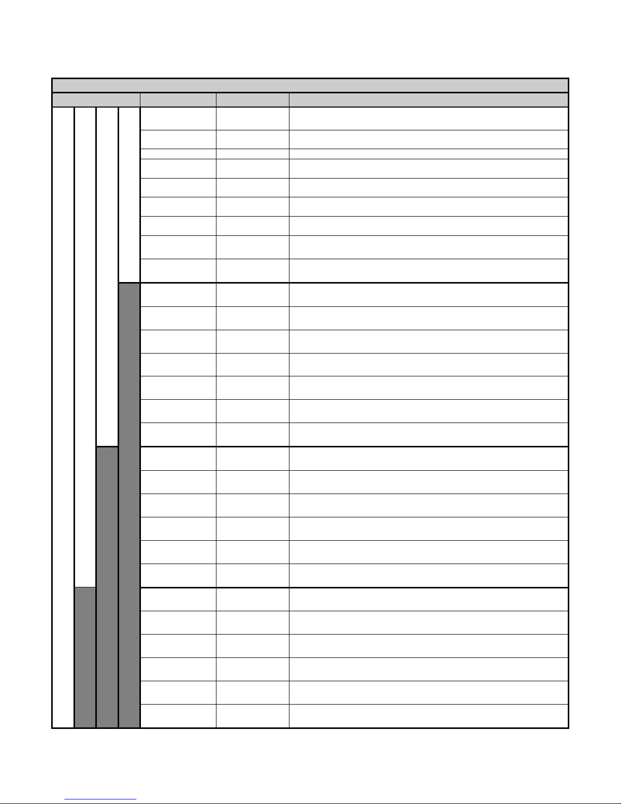
Available Parameter Descriptions
ESU-2400 Model Only
Mode
Parameter
Abbreviation
Description
Pulsed and Continuous Mode
mV RMS
mV
This is the mV measured directly from the RF current
transformer.
mA RMS
mA
This is the converted mA measurement based on the RF
transformer mV to mA attenuation ratio.
Power in Watts
Watts
This is the computed power based on load setting and mA
measured.
mV Peak
mV Pk
This is the maximum mV measured in the buffer.
NOTE: This is shown as an absolute value.
mV Peak – to –
Peak
mV P-P
This is the difference between maximum mV measured and
min mV measured.
mV Peak /
Peak – to – Peak
Vp/P-P
This is the ratio of Peak divided by
Peak to Peak millivolts.
mV Positive Peak
Only
mV Pk+
This is the maximum positive mV measured in the buffer.
For asymmetric waveforms this can determine if the output
polarity is reversed.
Crest Factor
CF
This is the ratio of peak to rms of the measured waveform.
Frequency
kHz
This the frequency of the measured waveform
Pulsed Mode Only
Time – Pulse On
Ton
This is the duration that the pulsed waveform is on in ms.
(See Diagram 1)
Time – Pulse Off
Toff
This is the duration that the pulsed waveform is off in ms.
(See Diagram 1)
Time – Total Cycle
Tcyc
This is the total cycle time of the pulsed waveform in ms.
(i.e. Ton + Toff). (See Diagram 1)
% Duty Cycle
%Duty
This is the ratio of the pulse on time (Ton)
versus cycle time (Tcyc). (See Diagram 1)
V Pulse
mV cyc
This represents the RMS mV over one pulsed cycle.
(See Diagram 1)
mA Pulse
mA cyc
This represents the RMS mA over one pulsed cycle.
(See Diagram 1)
Watts Pulse
Wcyc
This represents the RMS Watts over one pulsed cycle.
(See Diagram 1)
Ton
Toff
Tcyc
mV
mA
Watts
mVcyc
mAcyc
Wcyc
CF
Diagram 1 Pulsed mode (ESU-2400)
Page 95
83
ESU-2400H Only
Mode
Parameter
Abbreviation
Description
Pulsed Mode 3
Pulsed Mode 2
Pulsed Mode 1
Continuous
and Delayed
Mode
V Load
V
This is the load voltage calculated by the load resistance and current
measurement.
mA
mA
This is the converted mA measurement based on the RF transformer mV
to mA attenuation ratio.
Power in Watts
Watts
This is the computed power based on load setting and mA measured.
V Peak
V Pk
This is the maximum V measured in the buffer.
NOTE: This is shown as an absolute value.
V Peak – to –
Peak
V P-P
This is the difference between maximum V measured and min V
measured.
V Peak /
Peak – to – Peak
Vp/P-P
This is the ratio of Peak divided by
Peak to Peak volts.
V Positive Peak
Only
V Pk+
This is the maximum positive V measured in the buffer. For asymmetric
waveforms this can determine if the output polarity is reversed.
Crest Factor
CF
This is the ratio of peak to rms of the measured waveform.
Frequency
kHz
This the frequency of the measured waveform
Time – Pulse On
P1
Ton
This is the duration that the pulsed waveform is on in ms.
(See Diagram 2)
Time – Pulse Off
Toff
This is the duration that the pulsed waveform is off in ms.
(See Diagram 2)
Time – Total
Tcyc
This is the total cycle time of the pulsed waveform in ms.
(i.e. Ton + Toff). (See Diagram 2)
% Duty Cycle P1
%Duty
This is the ratio of the pulse on time (Ton)
versus cycle time (Tcyc). (See Diagram 2)
V Load P1
V P1
This is the load voltage calculated by the load and current measurement
for Pulse 1.(See Diagram 2)
mA P1
mAP1
This is the converted mA measurement of Pulse 1 based on the RF
transformer mV to mA attenuation ratio. (See Diagram 2)
Watts P1
WP1
This is the computed power in Watts based on load setting and mA
measured during Pulse 1. (See Diagram 2)
Pulse 2 Voltage
V Load P2
This is the load voltage calculated by the load and current measurement
for Pulse 2. (See Diagram 3)
Pulse 2 mA
mA P2
This is the converted mA measurement of Pulse 2 based on the RF
transformer mV to mA attenuation ratio. (See Diagram 3)
Pulse 2 Power in
Watts
Watts P2
This is the computed power in Watts based on load setting and mA
measured during Pulse 2. (See Diagram 3)
Pulse 2 Peak
Voltage
Vpk P2
This is the maximum voltage measured in the buffer for Pulse 2.
NOTE: This is shown as absolute value.
Pulse 2 Time On
Ton P2
This is the duration that the Pulse 2 waveform is on in ms.
Pulse 2 Duty
Cycle
% Duty P2
This is the ratio of the Pulse 2 on time (TonP2) divided by cycle time
(Tcyc)
Pulse 3 Voltage
V Load P3
This is the load voltage calculated by the load and current measurement
for Pulse 3. (See Diagram 4)
Pulse 3 mA
mA P3
This is the converted mA measurement of Pulse 3 based on the RF
transformer mV to mA attenuation ratio. (See Diagram 4)
Pulse 3 Power in
Watts
Watts P3
This is the computed power in Watts based on load setting and mA
measured during Pulse 3. (See Diagram 4)
Pulse 3 Peak
Voltage
Vpk P3
This is the maximum voltage measured in the buffer for Pulse 3.
NOTE: This is shown as absolute value.
Pulse 3 Time On
Ton P3
This is the duration that the Pulse 3 waveform is on in ms.
Pulse 3 Duty
Cycle
% Duty P3
This is the ratio of the Pulse 3 on time (TonP3) divided by cycle time
(Tcyc)
Page 96

84
ESU-2400H Pulsed Waveform Diagrams
The diagrams below show the relation of the pulsed waveform to measurements taken.
Diagram 2 (Pulsed mode 1 only)
Ton
Toff
Tcyc
Vcyc
mAcyc
Wcyc
CF
V Load
mA
Watts
Diagram 3 (Pulsed mode 2 only)
P1
P2
Tcyc
V P1
mA P1
Watts P1
V P2
mA P2
Watts P2
Diagram 4 (Pulsed mode 3 only)
P1
P2
Tcyc
mA P1
Watts P1
mA P2
Watts P2
P3
mA P3
Watts P3
Page 97

85
Show Graph –This key allows the user to display a graph of the latest RF measurement.
Graphs can be saved and loaded from internal memory or external USB storage.
Graph Buttons –
Back Arrow – Returns to RF Measurement Screen
Save – Stores waveform to a comma delimited file. This file can then be imported
into Microsoft® Excel.
Load – Opens previously saved waveform data.
Hold – Stops the waveform measurement update.
Zoom In – Expands the waveform to better view the individual data samples.
Zoom Out – Shows more waveform data to better view the overall waveform.
Full Zoom In
Full Zoom Out
Page 98

86
Averaging – This key allows the user to select the FAST, MEDIUM, or SLOW averaging
mode. Fast averaging will provide a quick response to incoming signals. Slow averaging
will provide a more stable display, but will be slower to respond to small changes in the
RF input signal. The value for the Averaging settings can be configured in the System
Setup screen.
Input Range – Allows the user to select the range for the RF input. The range can be
selected as 100mV, 1000mV, or Auto range.
Input Mode – Allows the user to select the mode for the RF measurement. The mode
can be selected as Continuous or Pulsed or Delayed. Continuous RF waveforms include
Cut, Bipolar, or Coag modes. Pulsed RF waveforms consist of a long period duty cycle
where the RF output might be active for 20 ms and inactive for 500 ms. Delayed RF
waveforms consist of Pulsed waveforms for which there is a large settling time which we
do not wish to read as valid data, typically with a settling time of up to 5 seconds.
NOTE: Delayed Mode and advanced Pulsed Modes are only available in ESU-2400H
model analyzers. (See ESU-2400H Advanced Input Modes, pg 89)
Test Load – This button shows a menu that allows the user to select internal load mode,
external load mode, or the combination of internal/external loads. The menu also allows
for the selection of the internal and external load values.
Page 99

87
Generator Type – The buttons labeled “Isolated” and “Gnd Ref” allow the user to select
whether the DUT being tested has an isolated output or ground referenced output. Some
generators such as Hyfrecators do not have a return pad and rely on earth ground as the
current return path. When testing these generators, select Gnd Ref and the ESU-2400
will configure the variable load to measure current from the active input to earth ground.
Configure Footswitch – This button opens the footswitch configuration menu that will
select the footswitch output and duration that is used when the footswitch trigger button
is pressed. To close the footswitch setup menu, press the Configure Footswitch button.
Page 100

88
Activate Footswitch – This button is used to trigger the footswitch output for the duration
that is configured in the Footswitch Setup menu. The footswitch can be deactivated
before the activation timeout period by pressing the Activate Footswitch button a second
time. While the footswitch output is active, the Activate Footswitch button will remain
highlighted with a yellow background.
 Loading...