

Page 1
Electrosurgical
Unit Analyzer
ESU-2300
USER MANUAL
Page 2

Page 3

BC BIOMEDICAL
ESU-2300
TABLE OF CONTENTS
WARNINGS, CAUTIONS, NOTICES ........................................................................... 2
DESCRIPTION............................................................................................................. 7
OVERVIEW.................................................................................................................. 9
SCREENS.................................................................................................................... 17
POWER UP SETTINGS............................................................................................... 24
TEST SETUPS............................................................................................................. 26
ERROR MESSAGES ................................................................................................... 48
®
DFA
TECHNOLOGY .................................................................................................. 50
MANUAL REVISIONS.................................................................................................. 51
WARRANTY................................................................................................................. 51
SPECIFICATIONS ....................................................................................................... 52
NOTES......................................................................................................................... 54
1
Page 4

WARNING - USERS
The ESU-2300 Analyzers are for use by
skilled technical personnel only.
WARNING - USE
The ESU-2300 Analyzers are intended for testing
only and they should never be used in
diagnostics, treatment or any other capacity
where they would come in contact with a patient.
WARNING - MODIFICATIONS
The ESU-2300 Analyzers are intended for use
within the published specifications. Any
application beyond these specifications or any
unauthorized user modifications may result in
hazards or improper operation.
WARNING - CONNECTIONS
All connections to patients must be removed
before connecting the Device Under Test (DUT)
to the Analyzer. A serious hazard may occur
if the patient is connected when
testing with the Analyzer.
Do not connect any leads from the patient
directly to the Analyzer or DUT.
WARNING - TEST LEADS
There are retractable ends on the test leads for
use with the ESU to avoid possible electric
shock, skin burns or personal injury.
Do not touch any metal on the
banana plugs or probes.
2
Page 5

WARNING - POWER SUPPLY
Unplug the Power Supply before
cleaning the surface of the Analyzer.
WARNING - LIQUIDS
Do not submerge or spill liquids on the Analyzer.
Do not operate the Analyzer if internal
components not intended for use with fluids may
have been exposed to fluid, as the internal
leakage may have caused corrosion and be a
potential hazard.
3
Page 6

CAUTION - SERVICE
The ESU-2300 Analyzers are intended to be
serviced only by authorized service personnel.
Troubleshooting and service procedures
should only be performed by
qualified technical personnel.
CAUTION - ENVIRONMENT
The ESU-2300 Analyzers are intended to
function between 15 and 30 °C.
Exposure to temperatures outside this range can
adversely affect the performance of the Analyzer.
CAUTION - VENTILATION
The ESU-2300 Analyzers include ventilation grills
on either side of the units to help prevent
overheating during operation. These grills and
internal fan should not be blocked.
Continuing to apply a high-level ESU signal
after an Error Message,
can result in damage to the unit.
CAUTION - CLEANING
Do not immerse. The Analyzer should be
cleaned by wiping gently with a damp, lint-free
cloth.
CAUTION - INSPECTION
The ESU-2300 Analyzers should be
inspected before each use for wear and
the Analyzer should be serviced
if any parts are in question.
4
Page 7
NOTICE – SYMBOLS
Symbol Description
Caution
(Consult Manual for Further Information)
RF Current Transformer
2002/95/EC, do not dispose of this
product as unsorted municipal waste.
Per European Council Directive
NOTICE – ABBREVIATIONS
A/D
c centi- (10
CF Crest Factor
DFA Digital Fast Acquisition
DUT Device Under Test
ESU Electrosurgical Unit
Ext External
Hz hertz
Int Internal
k kilo- (10
kg kilograms
kHz kilohertz VDC Direct Current Voltage
lbs pounds
Max Maximum
M Mega- (10
MHz Megahertz
µ micro- (10
µA microampere
m Milli- (10
mA milliampere
mHz millihertz
mm millimeter
ms millisecond
mV millivolts
Min Minimum
-2
)
3
)
6
)
-6
)
-3
)
# Number
Ω Ohm
PC Personal Computer
Pk Peak
% Percentage
RF Radio Frequency
RMS Root Mean Square
sec seconds
sec. section
US United States
V Volt
5
Page 8

USER ASSUMES FULL RESPONSIBILITY FOR UNAUTHORIZED
EQUIPMENT MODIFICATIONS OR APPLICATION OF EQUIPMENT
OUTSIDE OF THE PUBLISHED INTENDED USE AND
SPECIFICATIONS. SUCH MODIFICATIONS OR APPLICATIONS
MAY RESULT IN EQUIPMENT DAMAGE OR PERSONAL INJURY.
BC GROUP INTERNATIONAL, INC. RESERVES THE RIGHT TO
MAKE CHANGES TO ITS PRODUCTS OR SPECIFICATIONS AT
ANY TIME, WITHOUT NOTICE, IN ORDER TO IMPROVE THE
DESIGN OR PERFORMANCE AND TO SUPPLY THE BEST
POSSIBLE PRODUCT. THE INFORMATION IN THIS MANUAL HAS
BEEN CAREFULLY CHECKED AND IS BELIEVED TO BE
ACCURATE. HOWEVER, NO RESPONSIBILITY
IS ASSUMED FOR INACCURACIES.
NOTICE – CONTACT INFORMATION
NOTICE – DISCLAIMER
NOTICE – DISCLAIMER
BC BIOMEDICAL
BC GROUP INTERNATIONAL, INC.
PO BOX 25125
9415 GENTRY AVE
ST. LOUIS, MO 63125
USA
1-800-242-8428
314-638-3800
www.bcgroupintl.com
sales@bcgroupintl.com
Manual ESU-2300 Series Copyright © 2007
www.bcgroupintl.com
Made in the USA
10/07 Rev 01
6
Page 9

BC BIOMEDICAL
ESU-2300
ELECTROSURGICAL UNIT ANALYZER
The Model ESU-2300 is a high-accuracy Electrosurgical Analyzer. The “measurement
engine” of the ESU-2300 is a specially-engineered True-RMS RF Ammeter and Wattmeter,
particularly suited to measuring the complex RF waveforms produced by electrosurgical
generators. The ESU-2300 has been designed to comply with electrosurgical manufacturer
industry standard current sensing technology, and thus utilizes an internal precision RF
Current Transformer. The analyzer utilizes a precision internal test load resistor network.
The ESU-2300 is intended to be routinely used to measure the various parameters relating
to the testing and performance validation of electrosurgical generators. The Patent Pending
®
DFA
Technology allows the ESU-2300 to aggressively digitize the complex electrosurgical
generator waveform, analyze its components and provide highly accurate and stable
results. It may be used as a stand-alone meter or in conjunction with a PC utilizing the
optional software.
7
Page 10

The following are highlights of some of the main features:
• TRUE RMS READINGS USING PATENT PENDING DFA
TECHNOLOGY
• INDUSTRY STANDARD CURRENT SENSING TECHNOLOGY
• RF CURRENT (mA) AND POWER (WATTS) CAN BE
DISPLAYED
• INTERNAL PRECISION LOAD RESISTOR NETWORK: 50 Ω TO
750 Ω OHMS IN 50 Ω INCREMENTS
• EXTERNAL LOAD RESISTOR CAPABILITY – USES THE
EXTERNAL RESISTOR VALUE AS A DISCRETE VALUE OR
ADD IT TO ANY INTERNAL LOAD RESISTOR VALUE
• 2.5% OF READING ACCURACY ON RF CURRENT (mA)
• 4% OF READING ACCURACY ON RF POWER (WATTS)
• INTERNAL LOAD RESISTOR NETWORK IS COOLED WITH
TEMPERATURE AND POWER CONTROLLED COOLING FAN
• USES AN INTERNAL 0.1:1 RATIO PRECISION RF CURRENT
TRANSFORMER
®
• INDEPENDENT CQM (REM/ARM) RESISTOR NETWORK: 1 Ω
TO 500 Ω IN 1 Ω INCREMENTS
• RF LEAKAGE MEASUREMENTS THROUGH 200 Ω TEST LOAD
• INTERNAL RECHARGEABLE BATTERY ALLOWS OPERATION
INDEPENDENT OF LINE POWER
• LARGE GRAPHICS DISPLAY WITH CURSOR SELECTION
OF OPTIONS AND SETUP OF PARAMETERS
• DIGITAL DATA OUTPUT VIA USB
• REMOTE CAPABILITIES USING RS232 AND USB
• PC BASED INTERFACE PROGRAM OPTIONAL
• DIGITAL CALIBRATION – NO POTS TO TURN
• SELECTABLE DISPLAY OPTIONS
• TACTILE KEYS WITH AUDIO FEEDBACK
8
Page 11

STANDARD ACCESSORIES:
BC20 – 00125 ACCESSORY KIT (TEST LEADS)
BC20 – 21105 UNIVERSAL POWER SUPPLY
BC20 – 41352 COMMUNICATIONS CABLE (USB)
BC20 – 41341 COMMUNICATIONS CABLE (RS232)
BC20 – 205XX STANDARD POWER ADAPTER
(International Options, see Page 15 for details)
OPTIONAL ACCESSORIES:
BC20 – 00232 BNC TO BNC CABLE
BC20 – 41356 CD, ESU2300 INTERFACE SOFTWARE
VISHAY-DALE NH-250 PRECISION 1% TOLERANCE NON-INDUCTIVE
LOAD RESISTORS:
BC20-00200 5 Ω, 250 WATT RESISTOR
BC20-00201 10 Ω, 250-WATT RESISTOR
BC20-00202 20 Ω, 250-WATT RESISTOR
BC20-00203 30 Ω, 250-WATT RESISTOR
BC20-00204 50 Ω, 250-WATT RESISTOR
BC20-00205 100 Ω, 250-WATT RESISTOR
BC20-00206 200 Ω, 250-WATT RESISTOR
BC20-00207 300 Ω, 250-WATT RESISTOR
BC20-00208 500 Ω, 250-WATT RESISTOR
BC20-00209 1000 Ω, 250-WATT RESISTOR
BC20-00210 2000 Ω, 250-WATT RESISTOR
BC20-00211 3000 Ω, 250-WATT RESISTOR
BC20-00212 4000 Ω, 250-WATT RESISTOR
BC20-00213 5000 Ω 250-WATT RESISTOR
BC20-00240 POWER RESISTOR BANANA JACK ADAPTER
(2 PER SET)
9
Page 12
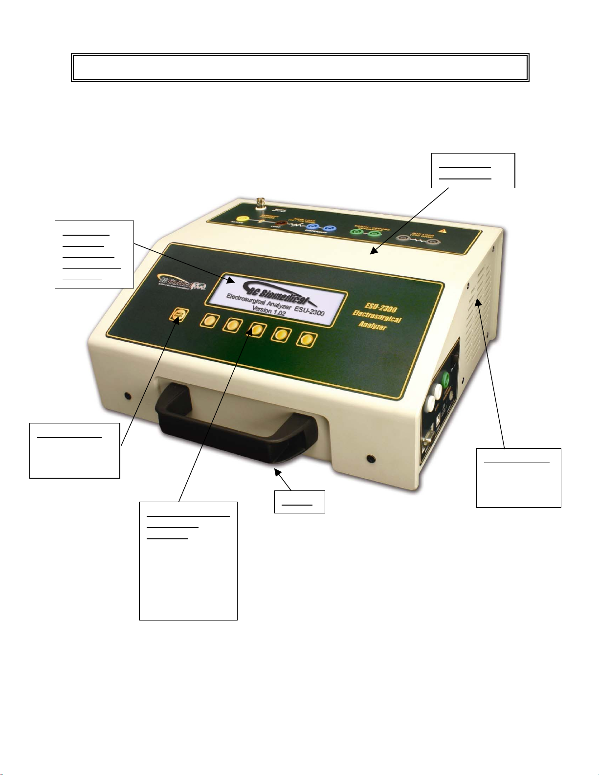
OVERVIEW
This section looks at the layout of the ESU-2300 and gives descriptions of the elements
that are present.
High Impact
Kydex Case
Large LCD
Graphical
Display with
High Intensity
Backlight
Back Light Key
for turning on
and off the
backlight
Ventilation Grill
(Both Sides)
for efficient load
resistor cooling
Handle
5 Light Touch Keys
for Dynamic
functions:
These keys are
labeled in the
bottom portion of
the screen and
change function
based on operating
mode.
10
Page 13

C
Q
r
A
A
Oscilloscope
Output
BNC connector
Dispersive Jacks
Banana Jacks for
connection to generator
patient return path
ux Test Load Jacks
Banana Jacks for
use during RF
leakage tests
ctive Jack
Banana Jack
input for RF
signal from
generator
CQM Test Jacks
Banana Jacks for use during
CQM (REM/ARM) and
M Tests
REC
Loop Jack
Banana Jack for
use when an
external load
resistor is
attached
Earth/Ground Jack
Banana Jack for use connecting the unit
to a ground when running Leakage Tests
while utilizing battery powe
Earth/Ground
Reference Jacks
Banana Jacks for
use during RF
leakage tests
Power On/Off
Rocker Switch
RS232 (DB9)
Comm Port
USB
omm Port
LED Indicators
Line Power
Battery Charging
11
External Power Supply
Kycon 3 position
locking connector
Page 14

Accessory Kit, BC20 – 00125:
A
A
ctive
Leads
RECQM Lead
(Prong)
CQM Lead
(No Prong)
Dispersive
Lead
Jumper
Leads
Earth/Gound
Lead
Banana
Jack
lligator
Clips
Ground
Lug
12
Page 15

GENERAL OPERATION
The ESU-2300 is controlled by 5 light touch keys for navigation, plus 1 light touch key for
LCD display backlight control. The navigation keys allow the user to move around within
the displayed parameters, select the desired options, choose a specific category and
control the setup for the unit. When a key is depressed there is an audio click when it is
accepted, or a “Razz” tone if the key is invalid.
A large LCD graphics display with high intensity white backlight provides the user with
information about the current status of the device configuration options, test results and
more. The display identifies the function of each key on a dynamic basis. As the operation
mode changes, the key functions change to suit the operating mode.
BACKLIGHT KEY
The Graphic LCD display may be viewed with or without the backlight. Depressing any key
will activate the backlight. However, since the backlight will drain the internal rechargeable
battery at an accelerated rate if left on, it will automatically be shut off after a user
programmable delay when running the ESU-2300 on battery power.
The key is provided to toggle the backlight on or off at any time.
NOTE: The backlight parameter in the System Setup screen may be set to Off, 1-20 sec or
Always On.
13
Page 16

FUNCTION KEYS
There are five keys that are used to provide general operational control. The
functions of the keys vary depending on the current screen. The section of the screen
just above the key indicates its current meaning.
NOTE: Only functions that are available to the user will be visible at any given time.
Sample Function Key Labeling
SERIAL COMMUNICATION
There are two serial ports on the side panel. One is a standard USB port and the other is a
DB9 RS232 port. The RS-232 Port is used for field Firmware upgrades via the FLASH
Update PC Utility and the USB Port is used to interface with a PC for remote control
operation or digitized electrosurgical waveform capture.
OSCILLOSCOPE OUTPUT
A BNC connector is provided to connect an oscilloscope to the unit. This output is an
uncalibrated attenuated version of the ESU Generator output waveform.
POWER SWITCH
The main power switch for the Analyzer is located on the side panel.
14
Page 17

LINE POWER
A Kycon 3 position locking connector is provided for the 9 VDC external universal power
supply for using the ESU-2300 with line power. When connected to line power, this
connection provides a connection for Earth/Ground.
NOTE: While operating the ESU-2300 on battery power, a Jumper Lead must be run
from the Earth/Ground Jack to an Earth/Ground point for all of the RF leakage tests.
(See Leakage Tests for more information.)
The Universal Power Supply takes a Standard Power Adapter Cable with Small
Standard Product Plug and Required International Connector (See Options Below).
15
Page 18

POWER UP SETTINGS
The unit may be setup to turn on using either the factory default settings or a custom set of
parameters as previously saved by the user (See Power Up Settings section for details).
16
Page 19

SCREENS
DISPLAY SCREEN
When the ESU-2300 is first powered up, the DISPLAY SCREEN will be shown. This
screen contains 1 or 2 DISPLAY ZONES, the LOAD SETTING and the available
FUNCTION KEYS. Each Display Zone can be customized to show the desired parameter
of RF RMS Current in mA or RF RMS Power in Watts. The Load Mode Setting can be set
to show the desired Internal, External and Internal/External loads. The Load Selection can
be set to change the internal, external, or internal plus external load resistances.
DISPLAY ZONES
Sample Display Screen with
The Display Zones can be toggled through using .
The parameters can be changed using the key to enter the Display
Parameters Configuration Screen.
one Display Zone
Sample Display Screen with
two Display Zones
17
Page 20

LOAD SETTING
The Load Setting portion of the Display Screen shows the load selection and value that will
be used in testing. There are three load set up choices for testing with the ESU-2300:
Internal, External and Internal/External.
The Load Setting and value can be toggled through using the key to enter the
Display Parameters Configuration Screen.
In Internal mode, the user applies the Active Lead to the Active Jack and the Dispersive
Lead to the Dispersive Jack. The RF current is routed through the selected internal loads
and through the RF Current Transformer to measure the current and power.
In External mode, the user applies the Active Lead to the Active Jack and then connects
another lead from the Loop Jack to whichever external load resistor is in use. The
Dispersive Lead then goes to the other side of the external load resistor. In this mode, the
only component that sees the ESU Generator output in the ESU-2300 is the RF current
transformer. It is important to make sure that the external load resistance parameter in the
ESU-2300 is set to the real value of the external load(s) as this is what is used to calculate
Power.
18
Page 21

In Internal/External mode, the user applies the Active Lead to the Active Jack and then
connects another lead from the Dispersive Jack to whichever external load resistor is in
use. The Dispersive Lead then goes to the other side of the external load resistor. It is
important to make sure that the external load resistance parameter in the ESU-2300 is set
to the real value of the external load(s) as this is what is used to calculate Power.
FUNCTION KEYS
DISPLAY – This key will toggle between one or two Display Zones.
CHANGE – This key will enter the Display Parameters Configuration Screen where
parameters can be selected and changed.
HOLD – This key will freeze the current reading in the Display Zone.
RECQM – This key will enter the RECQM Test Screen.
SETUP – This key will enter the System Setup Screen.
19
Page 22

DISPLAY PARAMETERS CONFIGURATION SCREEN
The parameters on the DISPLAY SCREEN can be changed by using the key
to enter the DISPLAY PARAMETERS CONFIGURATION SCREEN. This screen adds a
highlight line to the DISPLAY SCREEN and changes the FUNCTION KEYS.
Sample Display Parameters
Configuration Screen with
the load value highlighted
Use the keys to highlight the parameter to change. The last
FUNCTION KEY will be . Use this key to return to the DISPLAY SCREEN.
Use the keys to sequence through the available values of the
highlighted parameter. The last FUNCTION KEY will be . Use this key to
save the current value.
NOTE: Using the keys to highlight the next parameter will also
save the current value.
NOTE: To save a custom configuration, see Power Up Settings section.
20
Page 23

SYSTEM SETUP SCREEN
The SETUP Mode allows the user to adjust the configuration of the unit. The SETUP
SCREEN can be entered using the key.
Sample System Setup
Screen
Use the keys to highlight the parameter to change. The last
FUNCTION KEY will be . Use this key to return to the DISPLAY SCREEN.
Use the keys to sequence through the available values of the
highlighted parameter. The last FUNCTION KEY will be . Use this key to
save the current value.
NOTE: Using the keys to highlight the next parameter will also
save the current value.
NOTE: To save a custom configuration, see Power Up Settings section.
21
Page 24

The following is a breakdown of the parameters available in the configuration of the unit
and their available options:
System Setup Configuration
Parameter Description Range
Off, 0-20 sec,
Always on
(Factory Default = 10)
0-100% (Read Only)
Battery or Line
(Read Only)
Defaults
Custom
Set Current as Custom
Backlight
Battery Life
Power Source
Power up with
Controls whether the backlight is on or off or how
long to wait for user input before automatically
turning off the backlight in battery powered mode.
Displays remaining battery life (charge) in percent
Displays whether the unit is on battery power or
line powered
Determines the power up mode of the ESU-2300.
The default mode shows a single mA parameter
display. Set this parameter to custom to display
the saved startup mode. Set this parameter to
Save current as custom to save the settings for the
next time power is cycled.
1024
2048
4096
8192
16384
32768
Num A/D Samples
Sets the number of A/D converter readings used in
each mA RMS computation. A higher setting
requires more computation and is slower, but
results in a more stable reading.
(Factory Default =
32768)
Sets the number of mA RMS readings that are
Display Averaging
Software
averaged. A higher number will cause the display
to update slower, but will give a more stable
reading.
Displays current software program.
1-30 Readings
(Factory Default = 15)
(Read Only)
22
Page 25

CQM/RECQM (REM/ARM) TEST SCREEN
The RECQM TEST SCREEN can be entered using the key from the
DISPLAY SCREEN.
Sample RECQM Test
Screen
Use the keys to change the value of the resistance setting. This
setting ranges from 1 Ω to 500 Ω in 1Ω increments. The last FUNCTION KEY will be
. Use this key to return to the DISPLAY SCREEN.
23
Page 26

POWER UP SETTINGS
The ESU-2300 allows the user to customize the settings that the unit will have on Power
Up. The “Power up with” parameter in the System Setup Menu allows for the selection of
either Default or Custom selections.
Use to enter the SETUP SCREEN. Use the keys to
highlight the “Power up with” parameter.
Use the keys to change the parameters to Default, Custom or Set
Current as Custom. The last FUNCTION KEY will be . Use this key to
save the current value.
NOTE: Using the keys to highlight the next parameter will also
save the current value.
The last FUNCTION KEY will then be . Use this key to return to the
DISPLAY SCREEN.
24
Page 27

Default
If this option is selected, the unit will power up to the dual display zone screen, which will:
• Show the mA and Watts readings
• Put the ESU-2300 into Internal Load mode
• Use 300 ohms as the default internal load
Custom
If this option is selected, the unit will Power Up using the unique sets of parameters that
were last customized and saved by the user. The DISPLAY SCREEN will use the
parameters in the Display Zones that were last configured and saved by the user.
Set Current as Custom
This choice is provided to create the set of custom startup screen parameters. The user
simply configures each screen to show the desired parameters and then enters the Set
Current as Custom choice in the SETUP SCREEN. The current configuration is saved as
the Custom Power Up values and will be used when the “Power up with” parameter is set to
Custom. This configuration will remain the Custom configuration until it is written over
using the Set Current as Custom option in the “Power up with” parameter.
25
Page 28

TEST SETUPS
The purpose of this test is to verify the output accuracy of the Electrosurgical Generator
Device Under Test (DUT) at a given RF power setting, based on the selected internal
precision test load (50 Ω to 750 Ω in 50 Ω increments) from the ESU-2300 resistor
network. The ESU-2300 should always be set to match the electrosurgical generator
manufacturer’s specified test load for the mode and output waveform selected.
Connections
Monopolar ouputs:
1. Yellow Active Lead from Active Jack on ESU-2300 to DUT Output.
GENERATOR OUTPUT TESTS USING INTERNAL
2. Blue Dispersive Lead from Dispersive Jack on ESU-2300 to DUT Dispersive.
ESU (DUT)
Active
Electrode
ESU (DUT)
Patient Return/
Dispersive
Electrode
26
Page 29

Bipolar outputs:
1. Yellow Active Lead from Active Jack on ESU-2300 to DUT Bipolar Output
Electrode #1.
2. Second Yellow Active Lead from Dispersive Jack on ESU-2300 to DUT Bipolar
Output Electrode #2.
Bipolar
Electrode #1
ESU-2300 Screen
ESU (DUT)
ESU (DUT)
Bipolar
Electrode #2
DISPLAY SCREEN with LOAD SETTING set to Internal and Load Value set to the
desired number.
Results
Watts reading on DISPLAY SCREEN will display the measured power through the
currently selected load resistance. The DUT specs should be verified based on this
information.
27
Page 30

Information
Many electrosurgical generators vary their output power based on the measured load
impedance (the resulting electrical impedance of the human tissue being cut or
coagulated). One such trade-name for this functional characteristic is “Tissue
Response Technology” (which was originally offered by Covidien Valleylab, Boulder,
Colorado). They start out by applying a lower power signal to measure the load, and
then adjust the final output to match what is set on the front panel control setting.
When testing electrosurgical generators that utilize this level of technology, it is
advisable to give the ESU-2300 analyzer a few seconds to accurately measure the final
power of the generator. There is almost always a specified power curve that plots
output power to load resistance. Many electrosurgical generators have a peak power at
around 300-500 ohm range, with decreased delivered power to the actual load at lower
and higher impedances.
A typical power output vs. test load impedance “load curve” for an electrosurgical
generator is as follows:
28
Page 31

GENERATOR OUTPUT TESTS WITH EXTERNAL LOADS
The purpose of this test is to verify the output accuracy of the Electrosurgical Generator
Device Under Test (DUT) at a given RF power setting, based upon an attached external
load resistor. The external load resistor attached to the ESU-2300 should always be set
to match the electrosurgical generator manufacturer’s specified test load for the mode
and output waveform selected.
Connections
Monopolar:
1. Yellow Active Lead from Active Jack on ESU-2300 to External Load.
2. External Load to DUT Output.
3. Blue Dispersive Lead from Loop Jack on ESU-2300 to DUT Dispersive.
ESU (DUT)
Active
ESU (DUT)
Patient Return/
Dispersive
Electrode
29
Page 32

Bipolar:
1. Yellow Active Lead from Active Jack on ESU-2300 to External Load.
2. External Load to DUT Bipolar Output Electrode #1.
3. Second Active Lead from Loop Jack on ESU-2300 to DUT Bipolar Output
Electrode #2.
ESU (DUT)
Bipolar
Electrode #1
ESU (DUT)
Bipolar
Electrode #2
ESU-2300 Screen
DISPLAY SCREEN with LOAD SETTING set to External and Load Value set to the
desired number.
Results
Watts reading on DISPLAY SCREEN will display the measured power through the
external load resistance(s). The DUT specs should be verified based on this
information.
30
Page 33

Information
Many electrosurgical generators vary their output power based on the measured load
impedance (the resulting electrical impedance of the human tissue being cut or
coagulated). One such trade-name for this functional characteristic is “Tissue
Response Technology” (which was originally offered by Covidien Valleylab, Boulder,
Colorado). They start out by applying a lower power signal to measure the load, and
then adjust the final output to match what is set on the front panel control setting.
When testing electrosurgical generators that utilize this level of technology, it is
advisable to give the ESU-2300 analyzer a few seconds to accurately measure the final
power of the generator. There is almost always a specified power curve that plots
output power to load resistance. Many electrosurgical generators have a peak power at
around 300-500 ohm range, with decreased delivered power to the actual load at lower
and higher impedances.
A typical power output vs. test load impedance “load curve” for an electrosurgical
generator is as follows:
31
Page 34

GENERATOR OUTPUT TESTS WITH
INTERNAL / EXTERNAL TEST LOADS
The purpose of this test is to verify the output accuracy of the Electrosurgical Generator
Device Under Test (DUT) at a given RF power setting, based on the selected internal
precision test load (50 Ω to 750 Ω in 50 Ω increments) from the ESU-2300 resistor
network, in addition to series-connected external load resistor. The resulting test load
(the ESU-2300 internal load + the external load) should always be set to match the
electrosurgical generator manufacturer’s specified test load for the mode and output
waveform selected.
Connections
Monopolar:
1. Yellow Active Lead from Active Jack on ESU-2300 to External Load.
2. External Load to DUT Output.
3. Blue Dispersive Lead from Dispersive Jack on ESU-2300 to DUT Dispersive.
ESU (DUT)
Active
Electrode
ESU (DUT)
Patient Return/
Dispersive
Electrode
32
Page 35

Bipolar:
1. Yellow Active Lead from Active Jack on ESU-2300 to External Load.
2. External Load to DUT Bipolar Output Electrode #1.
3. Second Yellow Active Lead from Dispersive Jack on ESU-2300 to DUT Bipolar
Output Electrode #2.
ESU (DUT)
Bipolar
Electrode #1
ESU (DUT)
Bipolar
Electrode #2
ESU-2300 Screen
DISPLAY SCREEN with LOAD SETTING set to Internal/External and Load Value set to
the desired number.
Results
Watts reading on DISPLAY SCREEN will display the measured power through the
internal load resistance(s) and the external load resistance(s). The DUT specs should
be verified based on this information.
33
Page 36

Information
Many electrosurgical generators vary their output power based on the measured load
impedance (the resulting electrical impedance of the human tissue being cut or
coagulated). One such trade-name for this functional characteristic is “Tissue
Response Technology” (which was originally offered by Covidien Valleylab, Boulder,
Colorado). They start out by applying a lower power signal to measure the load, and
then adjust the final output to match what is set on the front panel control setting.
When testing electrosurgical generators that utilize this level of technology, it is
advisable to give the ESU-2300 analyzer a few seconds to accurately measure the final
power of the generator. There is almost always a specified power curve that plots
output power to load resistance. Many electrosurgical generators have a peak power at
around 300-500 ohm range, with decreased delivered power to the actual load at lower
and higher impedances.
A typical power output vs. test load impedance “load curve” for an electrosurgical
generator is as follows:
34
Page 37

CQM (REM/ARM) TEST
The Return Electrode Control Quality Monitor Test Mode allows the user to test the
CQM/RECQM (REM/ARM) safety feature available on most electrosurgical generators.
This feature exists mainly to prevent high frequency burns caused when the dispersive
electrode contact with the patient degrades to a high impedance connection, resulting in
increased current density at the electrode site. To prevent this, electrosurgical
generators typically employ a dual-sided pad, with independent electrical connections
from each side of the pad to the generator. The generator utilizes special electronic
circuitry that circulates a small current flow at a specific frequency through this circular
electrical path to monitor the contact impedance between the pad and the patient.
There are two basic types of this safety feature:
1. A basic continuity type test, where the ESU is looking for a very low resistance
(usually < 20 ohms) between the two dispersive pads
2. A more advanced RECQM test where the generator usually tests for a
resistance between the two dispersive pads to be greater than 5 ohms and less
than 135 ohms, as well as testing whether the measured resistance has changed
by a certain percentage over the initial measured resistance.
The usual way to test these two safety features of the electrosurgical generators is to use
a separate decade box and go through the ranges, checking when the generator alarms
out. In the ESU-2300, however, a digitally adjustable resistor, separate from the internal
test load resistor network, gives the user the ability to do all testing with one device.
35
Page 38

In this feature, the resistance across the two white CQM Jacks can be varied from 0 Ω to
500 Ω in 1 Ω increments.
WARNING – CQM TEST
Do not connect the Electrosurgical Generator
Active Electrode while conducting this test.
Do not enable the Electrosurgical Output at any time.
Connections
For CQM (continuity type):
1. CQM Lead (without prong) from CQM Jacks on side of ESU-2300 to DUT
Dispersive.
For RECQM (resistance type):
1. RECQM Lead (with prong) from CQM Jacks on side of ESU-2300 to DUT
Dispersive
ESU (DUT)
Patient Return/
Dispersive
Electrode
36
Page 39

ESU-2300 Screen
RECQM SCREEN with OHMS SETTING set to the desired value.
Results
The DUT should be checked for appropriate alarms in both safety modes (CQM and
RECQM).
NOTICE – MANUFACTURER’S SPECS
The user must consult the manufacturer’s
manual for each DUT to determine the correct
test procedures and alarm specifications
to follow.
37
Page 40

This leakage test, specified by the IEC as Active (or Dispersive) Electrode to Ground, is
for testing the RF leakage to Earth/ Ground of an Isolated Output type CF
electrosurgical generator from a single active or dispersive lead. The test complies with
IEC 601.2.2, sec. 19.101b, fig, 104 and sec. 19.102, adopted by ANSI/AAMI HF18-
2001. The purpose of this test is to verify that open circuit RF leakage of the Device
Under Test (DUT) meets or exceeds the IEC specification.
NOTE: DO NOT TEST A EARTH REFERENCED TYPE BF ELECTROSURGICAL
GENERATOR WITH THIS TEST, THE RESULTING MEASUREMENT WILL BE
RF LEAKAGE TEST #1
ERRONEOUS.
WARNING – ONE LEAD AT A TIME
Only test one lead of the ESU Generator at a
time, either Active or Dispersive, not both.
38
Page 41

Connections
1. Either Active Lead from Active Jack on ESU-2300 to DUT Active Output.
or
Dispersive Lead from Active Jack on ESU-2300 to DUT Dispersive
2. Jumper Lead from Dispersive Jack on ESU-2300 to Earth/Ground on ESU-2300.
ESU (DUT)
Active
Electrode
39
Page 42

NOTE: When the ESU-2300 is being operated on battery power (not connected to line
power through the external power supply and consequently not connected to an Earth/
Ground reference), it is necessary to supply an Earth/Ground reference the unit prior to
performing any RF Leakage Tests.
To accomplish this, simply connect the Ground Lead from the Earth/Ground Jack on the
right side panel of the ESU-2300 to a Ground Alligator Clip. Attach this clip to a Ground
Lug that is plugged into an Earth/Ground in any standard wall outlet.
40
Page 43

ESU-2300 Screen
DISPLAY SCREEN with LOAD SETTING set to Internal and Load Value set to 200
ohm.
Results
Activate the Electrosurgical Generator Output and read the RF leakage measurement
as the mA leakage readings on the DISPLAY SCREEN. These readings should be
verified against the appropriate electrosurgical generator standards.
NOTE: Remember to disable the Electrosurgical Generator Output when testing is
completed.
41
Page 44

RF LEAKAGE TEST #2
This leakage test, specified by the IEC as Earth Reference Leakage Type BF (Load
Between Electrodes), is for testing the leakage to Earth/Ground of a Ground
Referenced Output type BF electrosurgical generator from the active output. This test
complies with IEC 601.2.2, sec. 19.101a, test 1, fig. 102, and sec. 19.102, adopted by
ANSI/AAMI HF18-2001. The purpose of this test is to verify that the RF leakage of the
Device Under Test (DUT) meets or exceeds the IEC specification.
Connections
1. Active Lead from Aux Jack on ESU-2300 to DUT Active Output.
2. Jumper Lead from Earth/Ground on ESU-2300 to Active Jack on ESU-2300.
3. Jumper Lead from Aux Jack on ESU-2300 to Dispersive Jack on ESU-2300.
4. Dispersive Lead from Dispersive Jack on ESU-2300 to DUT Dispersive.
ESU (DUT)
Patient Return/
Dispersive
Electrode
ESU (DUT)
Active
Electrode
42
Page 45

NOTE: When the ESU-2300 is being operated on battery power (not connected to line
power through the external power supply and consequently not connected to an Earth/
Ground reference), it is necessary to supply an Earth/Ground reference the unit prior to
performing any RF Leakage Tests.
To accomplish this, simply connect the Ground Lead from the Earth/Ground Jack on the
right side panel of the ESU-2300 to a Ground Alligator Clip. Attach this clip to a Ground
Lug that is plugged into an Earth/Ground in any standard wall outlet.
43
Page 46

ESU-2300 Screen
DISPLAY SCREEN with LOAD SETTING set to Internal and Load Value set to 200
ohm.
Results
Activate the Electrosurgical Generator Output and read the RF leakage measurement
as the mA leakage readings on the DISPLAY SCREEN. These readings should be
verified against the appropriate electrosurgical generator standards.
NOTE: Remember to disable the Electrosurgical Generator Output when testing is
completed.
44
Page 47

RF LEAKAGE TEST #3
This leakage test, specified by the IEC as Earth Reference Leakage Type BF (Load
from Active Electrode to Earth) is for testing the leakage to Earth/Ground of a Ground
Referenced Output type BF electrosurgical generator from the active output. This test
complies with IEC 601.2.2, sec. 19.101a, test 1, fig. 102, and sec. 19.102, adopted by
ANSI/AAMI HF18-2001. The purpose of this test is to verify that the RF leakage of the
Device Under Test (DUT) meets or exceeds the IEC specification.
Connections
1. Active Lead from Aux Jack on ESU-2300 to DUT Active Output.
2. Jumper Lead from Earth/Ground on ESU-2300 to Aux Jack on ESU-2300.
3. Jumper Lead from Earth/Ground on ESU-2300 to Dispersive Jack on ESU-2300.
4. Dispersive Lead from Active Jack on ESU-2300 to DUT Dispersive.
ESU (DUT)
Patient Return/
Dispersive
Electrode
ESU (DUT)
Active
Electrode
45
Page 48

NOTE: When the ESU-2300 is being operated on battery power (not connected to line
power through the external power supply and consequently not connected to an Earth/
Ground reference), it is necessary to supply an Earth/Ground reference the unit prior to
performing any RF Leakage Tests.
To accomplish this, simply connect the Ground Lead from the Earth/Ground Jack on the
right side panel of the ESU-2300 to a Ground Alligator Clip. Attach this clip to a Ground
Lug that is plugged into an Earth/Ground in any standard wall outlet.
46
Page 49

ESU-2300 Screen
DISPLAY SCREEN with LOAD SETTING set to Internal and Load Value set to 200
ohm.
Results
Activate the Electrosurgical Generator Output and read the RF leakage measurement
as the mA leakage readings on the DISPLAY SCREEN. These readings should be
verified against the appropriate electrosurgical generator standards.
NOTE: Remember to disable the Electrosurgical Generator Output when testing is
completed.
47
Page 50

ERROR MESSAGES
Several error messages are provided to indicate invalid operating conditions.
Input Overload
When the input signal rises above the range that is measurable by the system, the
“WARNING Input Overload” message will be shown.
NOTE: Although the input is protected from damage at these levels, the user should
immediately remove any input signal when this message is shown.
Sample Input Overload
Screen
High Load Temperature
When the measured load bank temperature goes over the Warning Temperature as set in
the factory setup stack, the “WARNING High Load Temperature” message will be shown.
The user should disable the electrosurgical generator output immediately and let the ESU-
2300 cool down for a period of time.
48
Page 51

Fan Blocked
If there is a mechanical problem with the internal fan, such as a locked bearing or some
physical item blocking the path of the fan blades, the “Warning Fan Blocked” message will
be shown. The user should check the unit for any obvious protrusions. The user should
not use the unit for any electrosurgical generator testing and should return the ESU-2300 to
the factory for immediate servicing.
Sample Fan Blocked
Screen
WARNING – FAN BLOCKED WARNING
Do not activate the electrosurgical generator to the
internal loads of the ESU-2300, as there will be no
way for the internal loads to cool down.
Disable Electrosurgery Generator Output Before Changing Load
This message will warn the user not to switch internal load resistances while the
electrosurgical generator output is active.
49
Sample Disable Output
Screen
Page 52

DFA®TECHNOLOGY
Our Patent Pending DFA® (Digital Fast Acquisition) Technology is a revolutionary new
method of measuring electrosurgical generator output power. A high-speed analog to
digital converter is used to digitize the high frequency, high power output of the
electrosurgery generator. An RF Current Transformer is used to convert the current signal
to a voltage signal, which is read by the A/D converter. By digitizing the signal, a more
accurate, frequency independent measurement can be made.
50
Page 53

MANUAL REVISIONS
A
A
Revision #
Program # Revisions Made
Rev 01 DT7377A Origination
LIMITED WARRANTY
WARRANTY
FROM DEFECTS IN MATERIALS AND WORKMANSHIP UNDER THE SERVICE FOR WHICH THEY
RE INTENDED. THIS WARRANTY IS EFFECTIVE FOR TWELVE MONTHS FROM THE DATE OF
SHIPMENT.
EXCLUSIONS: THIS WARRANTY IS IN LIEU OF ANY OTHER WARRANTY EXPRESSED OR
IMPLIED, INCLUDING, BUT NOT LIMITED TO ANY IMPLIED WARRANTY OF MERCHANTABILITY
OR FITNESS FOR A PARTICULAR PURPOSE.
BC GROUP INTERNATIONAL, INC. IS NOT LIABLE FOR ANY INCIDENTAL OR CONSEQUENTIAL
DAMAGES.
NO PERSON OTHER THAN AN OFFICER IS AUTHORIZED TO GIVE ANY OTHER WARRANTY OR
SSUME ANY LIABILITY.
REMEDIES: THE PURCHASER'S SOLE AND EXCLUSIVE REMEDY SHALL BE: (1) THE REPAIR OR
REPLACEMENT OF DEFECTIVE PARTS OR PRODUCTS, WITHOUT CHARGE. (2) AT THE OPTION
OF BC GROUP INTERNATIONAL, INC., THE REFUND OF THE PURCHASE PRICE.
: BC GROUP INTERNATIONAL, INC. WARRANTS ITS NEW PRODUCTS TO BE FREE
51
Page 54

SPECIFICATIONS
Current (RMS) 20 – 7000.0 mA RMS
Input Resolution 1 mA RMS
Voltage (Peak) 1000.0 mV
Resolution 0.1 mV
Frequency 10 kHz – 10 MHz
Accuracy
Current 7000 mA RMS
Resolution 1 mA
Wattage 999.9 Watts
Resolution 0.1 Watt
INPUT RANGE
2.5% of Reading on RF Current
or +15 mA, whichever is greater
4% of Reading on RF Power
or + 3 Watts, whichever is greater
CALCULATED RANGES
52
Page 55

DISPLAY
SETUP MEMORY
MEMORY RETENTION
OPERATING RANGE
STORAGE RANGE
CONSTRUCTION
SIZE
WEIGHT
CONNECTIONS
FAN
CQM/RECQM TEST FEATURE
LCD Graphical 240x64 Pixels
EEPROM, All Parameters
10 Years w/o Power
15 to 30 Degrees C
-40 to 60 Degrees C
Enclosure – Kydex
Face – Lexan, Back Printed
6 x 13.5 x 12 inches
152.4 x 342.9 x 304.8mm
(H x W x D)
< 17 lbs. (7.7 kg)
Input: Safety Jacks
Output: Serial DB-9 or USB
BNC oscilloscope output
120 mm Internal Fan
0-500 Ω Independent Digitally
Controlled Resistance in
1 Ω Increments
Accuracy: 2% of range or 2 Ω,
whichever is greater
POWER SUPPLY ADAPTER
9 VDC, 5 A
POWER CONSUMPTION
BATTERY
CHARGER
ON: less than 3 A
OFF: less than 250 µA
Type: 6V, 7.2 Amp Hour
Sealed Lead Acid
2-state internal independent
charger with float mode
P:/Manuals/BCGroup/…/ESU-2000/ESV-2300_UM_Rev01.doc
53
Page 56

NOTES
54
 Loading...