

Page 1
HIGH PRECISION / RESOLUTION
DIGITAL PRESSURE METERS
DPM-2300 SERIES
USER MANUAL
Page 2

Page 3

BC BIOMEDICAL
DPM-2300 SERIES
TABLE OF CONTENTS
WARNINGS, CAUTIONS, NOTICES .............................................................................. 2
DESCRIPTION............................................................................................................. 7
OVERVIEW.................................................................................................................. 12
KEYS............................................................................................................................ 19
OPTIONS ..................................................................................................................... 21
COMMUNICATIONS.................................................................................................... 22
MANUAL REVISIONS.................................................................................................. 29
PREVENTIVE MAINTENANCE.................................................................................... 29
WARRANTY................................................................................................................. 29
SPECIFICATIONS ....................................................................................................... 30
NOTES......................................................................................................................... 32
1
Page 4

WARNING - USERS
The DPM-2300 Series Meters are for use by
skilled technical personnel only.
WARNING - USE
The DPM-2300 Series Meters are intended for
testing only and they should never be used in
diagnostics, treatment or any other capacity
where they would come in contact with a patient.
WARNING - MODIFICATIONS
The DPM-2300 Series Meters are intended for use
within the published specifications. Any
application beyond these specifications or any
unauthorized user modifications may result in
hazards or improper operation.
WARNING - CONNECTIONS
All connections to patients must be removed
before connecting the Device Under Test (DUT)
to the Meter. A serious hazard may occur
if the patient is connected when
testing with the Meter.
Do not connect any leads from the patient
directly to the Meter or DUT.
WARNING - BATTERIES
Turn Power Off and unplug any Battery
Eliminator before replacing batteries or cleaning
the surface of the Meter.
WARNING - LIQUIDS
Do not submerge or spill liquids on the Meter.
Do not operate the Meter if internal components
not intended for use with fluids may have been
exposed to fluid, as the internal leakage may
have caused corrosion and be a potential hazard.
2
Page 5

CAUTION - SERVICE
The DPM-2300 Series Meters are intended to be
serviced only by authorized service personnel.
Troubleshooting and service procedures
should only be performed by
qualified technical personnel.
CAUTION - ENVIRONMENT
The DPM-2300 Series Meters are intended to
function between 15 and 30 °C.
Exposure to temperatures outside this range can
adversely affect the performance of the Meter.
CAUTION - MEDIA
The DPM-2300 Series Meter is to be used only
with a pure fluid or gas that is compatible with
Pyrex, Glass, Silicon, Alumina Ceramic, Epoxy,
RTV, gold , aluminum and nickel.
CAUTION – PRESSURE LINE
Purge pressure line with distilled water
following any application that introduces
liquid into the meter.
CAUTION - CLEANING
Do not immerse. The Meter should be cleaned
by wiping gently with a damp, lint-free cloth.
A mild detergent can be used if desired.
CAUTION - INSPECTION
The DPM-2300 Series Meters should be
inspected before each use for wear and
the Meter should be serviced
if any parts are in question.
3
Page 6

NOTICE – CE
The DPM-2300 Series Meters bear the mark
Based on the following testing standards:
ELECTROMAGNETIC COMPATIBILITY DIRECTIVE
EMC – Directive 89/336/EEC as amended by 92/31/EEC and 93/68/EEC
EN 61326-1:1997 + A1:1998 + A2:2001 + A3:2003
“Electrical equipment for measurement, control and
laboratory use – EMC requirements”
This equipment has been type tested by an independent, accredited testing laboratory
and compliance was demonstrated to the above standard to the extent applicable.
EMISSIONS
Radiated and Line Conducted Emissions
EN 61000-3-2:2000 Harmonic Current Emissions
EN 61000-3-3:1995 + A1:2001 Voltage Fluctuation and Flicker
IMMUNITY– CLASS C
EN 61000-4-2:1995 + A1:1998 + A2:2001 Electrostatic Discharge
EN 61000-4-3:2002 Radiated Electric Field Immunity
EN 61000-4-4:1995 + A1:2001 + A2:2001 Electrical Fast Transients / Bursts
EN 61000-4-5:1995 + A1:2001 Surge Voltage
EN 61000-4-6:1996 + A1:2000 Conducted Disturbance
EN 61000-4-11:1994 + A1:2001 Voltage Dips and Short Interrupts
LOW VOLTAGE DIRECTIVE
EC – Directive 73/23/EC
EN 61010-1:2001
“Safety requirements for electrical equipment for measurement, control, and
laboratory use – General requirements”
This equipment has been type tested and compliance was demonstrated
to the above standard to the extent applicable.
4
Page 7

NOTICE – SYMBOLS
Symbol Description
Caution
(Consult Manual for Further Information)
Center Negative
Direct Current
NOTICE – ABBREVIATIONS
c centi- (10-2)
C Celsius
0 centimeter water
cmH
2
° degree
DUT Device Under Test
Euro European
F Fahrenheit
FS Full Scale
hrs hours
Hz hertz
inHg inches mercury
0 inches water
inH
2
k kilo- (10
2
kg/cm
kilograms per centimeter squared
3
)
kHz kilohertz
Kpa kilopascal
-6
µ micro- (10
)
µA microampere
-3
m milli- (10
)
mA milliampere
mBar milliBar
mm millimeter
mmHg millimeter mercury
Ω ohm
Press Pressure
PSI pounds per square inch
PSIG pounds per square inch gauge
Sec seconds
Temp temperature
US United States
V volt
VDC Direct Current Voltage
5
Page 8

USER ASSUMES FULL RESPONSIBILITY FOR UNAUTHORIZED
EQUIPMENT MODIFICATIONS OR APPLICATION OF EQUIPMENT
OUTSIDE OF THE PUBLISHED INTENDED USE AND
SPECIFICATIONS. SUCH MODIFICATIONS OR APPLICATIONS
MAY RESULT IN EQUIPMENT DAMAGE OR PERSONAL INJURY.
BC GROUP INTERNATIONAL, INC. RESERVES THE RIGHT TO
MAKE CHANGES TO ITS PRODUCTS OR SPECIFICATIONS AT
ANY TIME, WITHOUT NOTICE, IN ORDER TO IMPROVE THE
DESIGN OR PERFORMANCE AND TO SUPPLY THE BEST
POSSIBLE PRODUCT. THE INFORMATION IN THIS MANUAL HAS
BEEN CAREFULLY CHECKED AND IS BELIEVED TO BE
ACCURATE. HOWEVER, NO RESPONSIBILITY
IS ASSUMED FOR INACCURACIES.
NOTICE – CONTACT INFORMATION
NOTICE – DISCLAIMER
NOTICE – DISCLAIMER
BC BIOMEDICAL
BC GROUP INTERNATIONAL, INC.
PO BOX 25125
9415 GENTRY AVE
ST. LOUIS, MO 63125
USA
1-800-242-8428
314-638-3800
www.bcgroupintl.com
sales@bcgroupintl.com
Manual DPM-2300 Series Copyright © 2007
www.bcgroupintl.com
Made in the USA
08/07 Rev 03
6
Page 9

BC GROUP
DPM-2300 SERIES
DIGITAL PRESSURE METERS
The Model DPM-2300 Series is a Microprocessor based High Precision High Resolution
Digital Pressure Meter family. These meters measure both gas and liquid pressures and
provide multiple engineering unit displays for the results. The unit may have one or two
pressure sensors and an optional temperature sensor input to measure pressure and
temperature all in one meter.
The DPM-2300 Series meters are intended to be used by skilled technicians in the
evaluation and servicing of a wide variety of medical equipment. The following are
highlights of some of the main features:
DPM-2301 (Basic Features):
• LARGE GRAPHICS DISPLAY WITH CURSOR SELECTION OF
OPTIONS AND SETUP OF PARAMETERS
• 0.05% FS PRESSURE ACCURACY
• STANDARD PRESSURE SCALES INCLUDE 13 DIFFERENT
ENGINEERING UNIT RANGES
(PSI, mmHG@0C, mmHg@20C, inHG@0C, inHg@20C,
cmH
kg/cm
O@20C, inH2O@4C, inH2O@20C, inH2O@60F,
2
2
, Kpa, Bar, mBar)
• MAX and MIN PRESSURE VALUE CAPTURE AND STORAGE
• DIGITAL CALIBRATION – NO POTS TO TURN
• SELECTABLE DISPLAY OPTIONS AND DIGIT SIZES
• BATTERY LIFE DISPLAY (0 to 100%)
• PROGRAMMABLE DIGITAL FILTER
• DISPLAY CONTRAST IS SOFTWARE ADJUSTABLE
• 24 BIT MEASUREMENT
• DIGITAL ZERO ADJUSTMENT – NO POTS TO TURN
• DC ANALOG OUTPUT (OPTIONAL)
DPM-2302 ADDS:
• RS232 SERIAL COMMUNICATIONS
SECOND PRESSURE SENSOR ADDS:
• INDEPENDENT PRESSURE CHANNEL
• SEPARATE AND COMBINED DISPLAY OPTION
7
Page 10

TEMPERATURE OPTION ADDS:
• YSI 700 OR 100 Ω
RTD TEMPERATURE PROBE INTERFACE
• -20.0 TO100.0 C / -4.0 TO 212.0 F TEMPERATURE RANGE
• 0.5% FS ACCURACY
• MAX and MIN TEMPERATURE VALUE CAPTURE AND STORAGE
OPTIONAL ACCESSORIES:
BC20 - 21100 BATTERY ELIMINATOR (US Version)
BC20 - 21101 BATTERY ELIMINATOR (Euro Version)
BC20 - 41337 COMMUNICATIONS CABLE (7Pin Mini-Din to DB 9 F)
BC20 - 30106 BC BIOMEDICAL SMALL SOFT SIDED CARRYING CASE
BC20 - 01005 UNIVERSAL PRESSURE ADAPTER KIT
BC20 - 01006 YSI TEMPERATURE CABLE
8
Page 11

AVAILABLE MODELS:
g
r
There are a numerous possible configurations for the DPM-2300. The meter can have one
or two pressure sensors and an optional temperature sensor input. There are a variety of
pressure transducer full-scale values and two types of temperature sensor inputs available.
It can be configured with or without and RS232 communications port and a Min/Max
pressure and temperature capture and hold function. The optional DC output provides a
DC voltage level output that is proportional to the full scale value of the pressure being
measured. The model number configuration guide below calls out these various options
and configurations. For additional details on the Pressure and Temperature Sensor
Ranges, see next pages.
DPM 230X XX XX XX XX
Options
DC = DC (Direct Current)
Analog Output
FC = Female Coupler CPC Connectors
MC = Male Insert CPC Connectors
Temperature Sensor
N = Not Applicable
Y7 = YSI 700
R1 = 100 Ω RTD
Pressure Sensor 2 (Port 2 Left)
N = Not Applicable
100 = Max 100 PSI (CPC Connector)
75 = Max 75 PSI (CPC Connector)
10 = Max 10 PSI (Luer Connector)
5 = Max 5 PSI (Luer Connector)
.3 = Max .3 PSI (Luer Connector)
Pressure Sensor 1 (Port 1Right)
N = Not Applicable
100 = Max 100 PSI (CPC Connector)
75 = Max 75 PSI (CPC Connector)
10 = Max 10 PSI (Luer Connector)
5 = Max 5 PSI (Luer Connector)
.3 = Max .3 PSI (Luer Connector)
2300 Series
2301 = Basic Model (Includes Min/Max)
2302 = RS232 Add
Di
ital Pressure Mete
9
Page 12

Pressure Sensor 100
Units Range
(Accuracy: .05%
FS = +/- 0.05 PSI)
PSI -13.500 to 100.000
mmHg 0C -698.2 to 5171.5
mmHg 20C -700.6 to 5190.3
inHg 0C -27.486 to 203.602
inHg 20C -27.586 to 204.342
cmH2O 20C -951.8 to 7043.2
inH2O 4C -373.6 to 2768.1
inH2O 20C -374.3 to 2772.9
inH2O 60F -374.1 to 2770.8
kg/cm2 -.9491 to 7.0306
kPa -93.08 to 689.48
mBar -930.8 to 6894.8
Bar -.9308 to 6.8948
Pressure Sensor 10
Units Range
(Accuracy: .05%
FS = +/- 0.005 PSI)
PSI -10.0000 to 10.0000
mmHg 0C -517.15 to 517.15
mmHg 20C -519.03 to 519.03
inHg 0C -20.3602 to 20.3602
inHg 20C -20.4342 to 20.4342
cmH2O 20C -704.32 to 704.32
inH2O 4C -276.81 to 276.81
inH2O 20C -277.29 to 277.29
inH2O 60F -277.08 to 277.08
kg/cm2 -.70307 to .70307
kPa -68.948 to 68.948
mBar -689.48 to 689.48
Bar -.68948 to .68948
mmHg 0C -698.2 to 3878.6
mmHg 20C -700.6 to 3892.7
inHg 20C -27.586 to 153.256
cmH2O 20C -951.8 to 5282.4
inH2O 4C -373.6 to 2076.1
inH2O 20C -374.3 to 2079.7
inH2O 60F -374.1 to 2078.1
Pressure Sensor 75
Units Range
(Accuracy: .05%
FS = +/- 0.0375 PSI)
PSI -13.500 to 75.000
inHg 0C -27.486 to 152.702
kg/cm2 -.9491 to 5.2730
kPa -93.08 to 517.11
mBar -930.8 to 5171.1
Bar -.9308 to 5.1711
mmHg 0C -258.57 to 258.57
mmHg 20C -259.51 to 259.51
inHg 20C -10.2171 to 10.2171
cmH2O 20C -352.16 to 352.16
inH2O 4C -138.40 to 138.40
inH2O 20C -138.64 to 138.64
inH2O 60F -138.54 to 138.54
Pressure Sensor 5
Units Range
(Accuracy: .05%
FS = +/- 0.0025 PSI)
PSI -5.0000 to 5.0000
inHg 0C -10.1801 to 10.1801
kg/cm2 -.35153 to .35153
kPa -34.473 to 34.473
mBar -344.74 to 344.74
Bar -.34474 to .34474
10
Page 13

Pressure Sensor .3
Units Range
(Accuracy: .05%
FS = +/- 0.00015 PSI,
+/- 0.01 cmH2O)
PSI -.30000 to .30000
mmHg 0C -15.514 to 15.514
mmHg 20C -15.571 to 15.571
inHg 0C -.61081 to .61081
inHg 20C -.61303 to .61303
cmH2O 20C -21.129 to 21.129
inH2O 4C -8.304 to 8.304
inH2O 20C -8.319 to 8.319
inH2O 60F -8.312 to 8.312
kg/cm2 -.021092 to .021092
kPa -2.0684 to 2.0684
mBar -20.684 to 20.684
Bar -.020684 to .020684
Temperature Sensor
Units Range
100 Ω RTD
(Accuracy: .5%
FS = +/- 0.5 C)
Degrees C -20.0 to 100.0
Degrees F -4.0 to 212.0
Temperature Sensor
Units Range
YSI 700
(Accuracy: .5%
FS = +/- 0.5 C)
Degrees C -20.0 to 100.0
Degrees F -4.0 to 212.0
11
Page 14
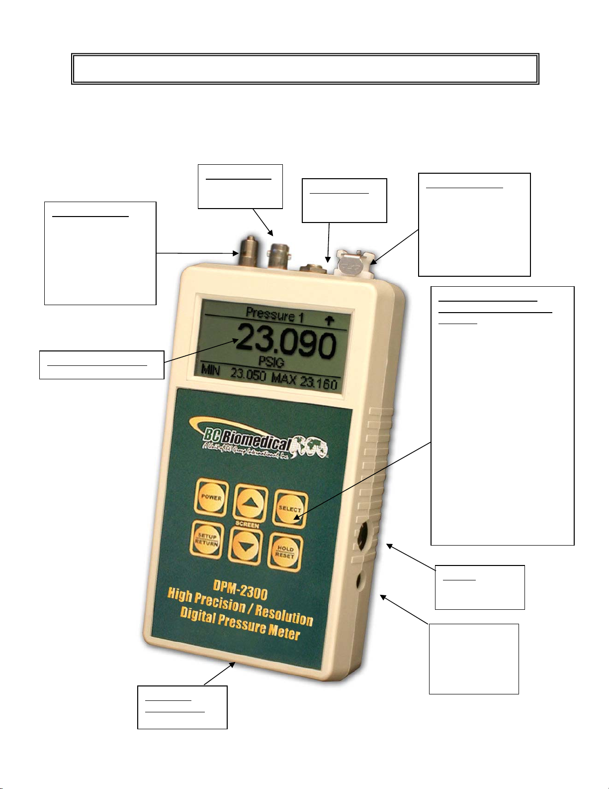
OVERVIEW
This section looks at the layout of the DPM-2300 and gives descriptions of the elements
that are present.
Pressure Port #2:
Luer Lock Connector
(or Female Coupler
CPC Connector
or Male Insert
CPC Connector,
Range and Option
Dependent)
LCD Graphical Display
Analog Output:
BNC (Optional)
Temperature:
¼” Phone Jack
(Optional)
Pressure Port #1:
Female Coupler
CPC Connector
(or Male Insert
CPC Connector,
Option Dependent
or Luer Lock,
Range Dependent)
6 Light Touch Keys for
Selecting Parameters and
Settings:
POWER for Turning Unit On
and Off
UP and DOWN Arrows for
Scrolling Through Selected
Options. When No Options
are Selected, for Changing
Display Screen
SELECT for Choosing
Setting or Parameter to
Change
SETUP/RETURN for
Entering and Exiting Setup
Menu
HOLD/RESET for Freezing
the Unit at its Current Setting
and for Clearing the Min/Max
Value in Capture Register
RS232:
7 PIN Mini-Din
(Optional)
Power
2.1 mm Jack
(Optional Battery
Eliminator)
9V Battery
Compartment
(Rear)
12
Page 15

MAIN SCREENS
– There can be up to five main screens, depending on the model. They
are PRESSURE 1, PRESSURE 2, TEMPERATURE, COMBINED and INPUTS. The
available screens can be toggled through using .
Pressure Port 1
Display with Min/Max
Option selected
Pressure Port 2
Display with Min/Max
Option selected
Temperature Display
with Min/Max Option
selected
Combined Screen showing:
Pressure Port 1
Pressure Port 2
Temperature
Input Identification Screen
Note: Sensor limits are
displayed based on
selected range.
13
Page 16

PRESSURE SCALE
– The pressure scale is indicated by the units displayed under
the reading. The scale can be changed by using to highlight the unit line and
to toggle the pressure units.
Pressure Units
PSI
mmHg 0C
mmHg 20C
inHg 0C
inHg 20C
cmH2O 20C
inH2O 4C
inH2O 20C
inH2O 60F
kg/cm2
kPa
mBar
Bar
NOTE: If the measured pressure is outside of the range of the instrument, an OVER
RANGE or UNDER RANGE message box will be displayed.
Typical display with
“Over Range”
message box.
14
Page 17

TEMPERATURE SCALE
– The temperature scale is indicated by the units displayed under
the reading. The scale can be changed by using to highlight the unit line and
to toggle the temperature units. The following is a breakdown of the available
temperature units and the measurement range for typical sensors:
Temperature Sensor
Units
Degrees C
Degrees F
NOTE: If the measured temperature is outside of the range of the instrument, an OVER
RANGE or UNDER RANGE message box will be displayed. If a probe is not connected,
the NO PROBE message box will be displayed.
Typical display with
“No Probe” message
box.
15
Page 18

SYSTEM SETUP
– The Setup Mode allows the user to adjust the configuration of the
meter. The Setup screen can be entered using the key. The parameters can be
changed by using to highlight the line and to toggle the available
options. The Setup screen can be exited using the key. The following is a
breakdown of the parameters available in the configuration of the unit and their available
options:
System Setup Configuration
Parameter Description Range
Display Min/Max
Analog Scale
Analog Source
Contrast Adjust
Auto Off Timer (Min)
Battery Life
Beep Length
Filter – Pres 1 (Sec)
Filter – Pres 2 (Sec)
Filter – Temp (Sec)
Software
Selects whether the Min and Max values will be
displayed on the main screens
(except COMBINED).
Analog Output Scaling voltage. This is the
maximum analog output voltage. The output is
scaled to this voltage over the positive input of the
selected source.
Selects the source reading for the analog output
Sets the contrast of the display screen.
Determines the period of inactivity before the meter
is turned OFF. A timer is started when the meter is
turned ON and is reset each time a key is pressed.
When the timer reaches the value set in this
parameter, the power is automatically turned OFF.
(NOTE: Setting this parameter to 0 disables the
Auto Off timer. When running from line power, the
meter does not automatically shut off.)
Displays current life of the battery.
At 10%, a warning screen will appear.
Sets volume for the audio beep.
Determines the number of samples that are
averaged in the digital filter. The software has a
Digital Filter that averages the readings to produce
a stable display.
(NOTE: Increasing this setting will cause a more
stable display. However, it will also cause a slower
response to small changes. The best setting is the
smallest number that provides a stable display.)
Displays current software program.
Yes/No
1.0 to 4.0 Volts
Pres1, Pres2, or
Temp
0-20
0-30 Minutes
0-100%
(Read Only)
0-16
0-10
(Read Only)
16
Page 19

ZEROING PRESSURE SCALES
– When there are no pressure inputs connected to the
unit, the display should read “0.” It may be necessary to zero the pressure scales to
remove any errors due to ambient conditions. This is done by depressing the
key until the zeroing instructions are displayed, then depressing
simultaneously to begin the process. The “ZEROING…” message will flash while the scale
is being zeroed. When the zeroing instructions are displayed again, the process is
complete.
NOTE: Each sensor needs to be zeroed separately.
17
Page 20

LOW BATTERY
– When the battery life reaches 10 percent, the LOW BATTERY message
box will be displayed.
Typical display with
“Low Battery” message
box.
NOTE: The unit is shipped with a red plug in the Power Input that prevents it from
accidentally being turning on, subsequently depleting the battery during transport. This
plug must be removed before use.
LINE POWER – A 2.1 mm jack is provided for the optional 9 VDC power supply
(BC20 - 21100, BC20 - 21101) that may be used for continuous run applications. It
bypasses the internal battery when plugged in.
18
Page 21

KEYS
Six tactile-touch keys are provided for system operation:
– This key turns the unit off and on. The unit will return to the main screen that
was active when it was turned off.
– In the DISPLAY MODE, these keys toggle the display through the
available main screens.
In the SELECT MODE, if a parameter has been highlighted, these keys will scroll through
the available settings.
– On any screen, there are a number of parameters that may be selected and
changed. This key sequences the cursor (Highlight) through those parameters.
– This key is used to Hold (freeze) and Reset (unfreeze) any of the input displays.
Depressing this key will hold the currently displayed Pressure or Temperature reading until
reset. Each input can be held independently.
When active, the word “HOLD” is in the display. Depressing this key on a screen that is
held will reset that input and remove the word “HOLD” from the display.
NOTE: In the composite screen, the hold feature requires that the specific input be
selected using before is used.
19
Page 22

– This key toggles the unit into and out of the Setup Mode. Depressing this key
will enter the Setup screen where the configuration can be viewed and adjusted.
Depressing the key again will exit the Setup Mode and return to the previously viewed main
screen. This will also save any changes to the internal EEPROM memory so they will be
retained even with the power turned off or battery removed.
20
Page 23

OPTIONS
ANALOG OUTPUT
– The unit may be ordered with a DC (Direct Current) Analog Output.
This option provides a filtered Analog Output that matches the displayed pressure or
temperature. Filtering is dependent on the Digital Filter Setting (See System Setup section
for more information). This is for slowly changing inputs. The output is scaled to match the
0 to Full pressure range of the selected sensor. The scaling voltage can be selected from
1.0 to 4.0 VDC in 0.1V increments.
The source for the analog output is selectable in the Setup Mode. The Analog Source
parameter can be selected to track Pressure 1 (Pres1), Pressure 2 (Pres2) or
Temperature (Temp).
21
Page 24

COMMUNICATIONS
Since the meter does not handle any high-bandwidth data links, the RS232 communication
port data link has been optimized to allow the user, through very simple instructions, to
control and interrogate the meter. The following section describes the JPC Protocol used
by the meter.
The JPC Protocol consists of 6 basic commands:
R - READ
W - WRITE
U - UPLOAD
Q - QUICKSEND
V - VERSION
X - CANCEL
The data format is standard ASCII and all data are BCD values.
The following is a breakdown of each of the commands and the way they are accessed.
The meter will echo all characters that are typed to it. When used with a terminal, this will
provide the appropriate display. When used with a computer system, this will provide direct
feedback of the fact that unit has accepted the data.
All commands are completed with a carriage return from the computer. All commands will
be acknowledged by a carriage return, line feed ($0D,$0A). If a command is not valid, the
meter will respond with “??”. All commands are not case sensitive.
22
Page 25

READ/WRITE COMMANDS
The READ command is utilized to read from the meter any of the gathered data. The
command is entered as a letter followed by 2 numbers, followed by a carriage return:
R(Location)(Return)
The 'R' indicates to the meter that the command is to be a READ command.
The Location contains two digits that indicate the data location that is to be read.
The carriage return indicates that the command is to be activated.
The WRITE command allows the user to update the system settings. The write command
is entered as a letter followed by 7 numbers, followed by a carriage return.
W(Location)(Data) (Return)
The 'W' indicates to the meter that the command is to be a WRITE command.
The Location contains two digits that indicate the data location that is to be read.
The Data contains five digits that indicate the data that is to be written at the desired
Location.
The carriage return indicates that the command is to be activated.
23
Page 26

LOCATION ACCESS DESCRIPTION RANGE
01 R
% BATTERY LIFE
REMAINING
0-100
02 R/W CONTRAST 0-20
03 R/W AUTO POWER OFF 0-30
04 R MODEL
0 Not Installed
1 100 PSI Max
05 R
PRESSURE 1 SENSOR
TYPE
2 75 PSI Max
3 10 PSI max
4 5 PSI max
5 0.3 PSI max
0 PSI
1 mmHg 0C
2 mmHg 20C
3 inHg 0C
4 inHg 20C
O 20C
2
O 4C
2
O 20C
2
O 60F
2
2
06 R/W PRESSURE 1 UNITS
5 cmH
6 inH
7 inH
8 inH
9 kg/cm
10 kPA
11 mBar
12 Bar
07 R/W PRESSURE 1 FILTER 0-60
08 R PRESSURE 1 See Note 1
09 R/W PRESSURE 1 MAX See Note 1, 3
10 R/W PRESSURE 1 MIN See Note 1, 3
0 Not Installed
1 100 PSI Max
11 R
PRESSURE 2 SENSOR
TYPE
2 75 PSI Max
3 10 PSI max
4 5 PSI max
5 0.3 PSI max
0 PSI
1 mmHg 0C
2 mmHg 20C
3 inHg 0C
4 inHg 20C
O 20C
2
O 4C
2
O 20C
2
O 60F
2
2
12 R/W PRESSURE 2 UNITS
5 cmH
6 inH
7 inH
8 inH
9 kg/cm
10 kPA
11 mBar
12 Bar
13 R/W PRESSURE 2 FILTER 0-60
14 R PRESSURE 2 See Note 1
15 R/W PRESSURE 2 MAX See Note 1, 3
16 R/W PRESSURE 2 MIN See Note 1, 3
24
Page 27

17 R
18 R/W TEMPERATURE UNITS
19 R/W TEMPERATURE FILTER 0-60
20 R TEMPERATURE See Note 2
21 R/W TEMPERATURE MAX See Note 2, 3
22 R/W TEMPERATURE MIN See Note 2, 3
TEMPERATURE SENSOR
TYPE
0 Not Installed
1 YSI 700
2 RTD 100
0 = C
1 = F
Note 1 – The units for the pressure data are determined by the setting in Location 6 and 12.
This may be set via the Write command or manually using the Range Key. See
Description Page for Ranges.
Note 2 – The units for the temperature data are determined by the setting in Location 18.
This may be set via the Write command or manually using the Range Key. See Description
Page for Ranges.
Note 3 – Writing to Min/Max will reset them to the current value. Any data up to 5 digits will
trigger the reset. This is the same function as selecting the Min/Max item in the display and
pressing the key.
25
Page 28

The following is an example of how the Read/Write commands are used. For display
purposes, the symbol <cR> will be used to identify a carriage return ($0D), and the symbol
<LF> will be used to identify a line feed ($0A).
Read Command Examples
Data Sent
Data Returned Meaning
R08<cR> R08<cR><LF> Echo of Command Sent
10.25 mmHg <cR><LF> 10.25 mmHg measured on Pressure Sensor 1
* End of Transmission
R11<cR> R11<cR><LF> Echo of Command Sent
5<cR><LF> Pressure Sensor 2 is a 0.3 PSI Max Sensor
* End of Transmission
Write Command Examples
Data Sent Data Returned Meaning
W124 <cR> W124<cR><LF> Echo of Command Sent
(Set Pressure Sensor 2 units to “inH2O@20C”)
W1200004<cR> W1200004<cR><LF> Echo of Command Sent
(Set Pressure Sensor 2 units to “inH2O@20C”)
* End of Transmission
W05100<cR> W05100<cR><LF> Echo of Command Sent
??<cR><LF> Invalid Command Response
(Location 05 is Read Only)
* End of Transmission
26
Page 29

UPLOAD COMMAND
The Upload command allows the user to read all of the selected device data from locations
1 through 22 with a single command. The data will be transmitted as a single block with
each location separated by a carriage return, line feed ($0D,$0A).
The following is the format for this command:
U (Return)
See the table in the Read Command section for details on the data structure.
QUICKSEND COMMAND
Quicksend is a feature that allows the user to receive an automatic update of all of the
meter data without any user interaction. When the Quicksend feature is turned ON, the
meter will automatically send all of the device data every half second. The Quicksend
feature is toggled ON and OFF with the Quicksend command.
The following is the format for the 'Q' command:
Q (RETURN)
See the table in the Read Command section for details on the data structure.
27
Page 30

VERSION COMMAND
The Version command allows the user to read the Software Version that the unit is running.
To read the Version, the following syntax is used:
V (RETURN)
CANCEL COMMAND
The CANCEL command is simply a way to re-establish proper control, should an error
occur or an incorrect command be transmitted. For the most part, an incorrect command
will simply be ignored and the meter will prepare for an additional command. However, a
command may be cancelled midstream by transmitting an 'X' (ASCII). This command does
not require a carriage return, nor will it acknowledge with a carriage return. However, it will
echo an 'X' to indicate that the CANCEL command has been received.
The command may also be utilized as a clear and/or acknowledgement of the meter being
on line.
28
Page 31

MANUAL REVISIONS
Revision #
Program # Revisions Made
Rev 01 DT7321CA Origination
Rev 02 DT7321CB Min/Max made standard, CPC Connector added
Rev 03 DT7321CB MC and FC option for CPC Connectors added
PREVENTIVE MAINTENANCE
CALIBRATION: Annually
PRESSURE LINE: Purge pressure line with distilled water following any application
that introduces liquid into the meter.
BATTERIES: When a “Low Battery” message is displayed, the battery should be
replaced immediately or the function of the unit may be impaired. The battery
compartment is located on the back of the unit. Use only 9 V Alkaline batteries.
LIMITED WARRANTY
WARRANTY: BC GROUP INTERNATIONAL, INC. WARRANTS ITS NEW PRODUCTS TO BE FREE
FROM DEFECTS IN MATERIALS AND WORKMANSHIP UNDER THE SERVICE FOR WHICH THEY
ARE INTENDED. THIS WARRANTY IS EFFECTIVE FOR TWELVE MONTHS FROM THE DATE OF
SHIPMENT.
EXCLUSIONS: THIS WARRANTY IS IN LIEU OF ANY OTHER WARRANTY EXPRESSED OR
IMPLIED, INCLUDING, BUT NOT LIMITED TO ANY IMPLIED WARRANTY OF MERCHANTABILITY
OR FITNESS FOR A PARTICULAR PURPOSE.
BC GROUP INTERNATIONAL, INC. IS NOT LIABLE FOR ANY INCIDENTAL OR CONSEQUENTIAL
DAMAGES.
NO PERSON OTHER THAN AN OFFICER IS AUTHORIZED TO GIVE ANY OTHER WARRANTY OR
ASSUME ANY LIABILITY.
REMEDIES: THE PURCHASER'S SOLE AND EXCLUSIVE REMEDY SHALL BE: (1) THE REPAIR OR
REPLACEMENT OF DEFECTIVE PARTS OR PRODUCTS, WITHOUT CHARGE. (2) AT THE OPTION
OF BC GROUP INTERNATIONAL, INC., THE REFUND OF THE PURCHASE PRICE.
29
Page 32
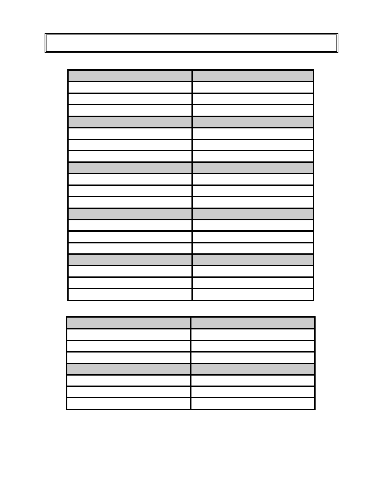
SPECIFICATIONS
PRESSURE SENSOR 100
-RANGE
-RESOLUTION
-ACCURACY
PRESSURE SENSOR 75
-RANGE
-RESOLUTION
-ACCURACY
PRESSURE SENSOR 10
-RANGE
-RESOLUTION
-ACCURACY
PRESSURE SENSOR 5
-RANGE
-RESOLUTION
-ACCURACY
PRESSURE SENSOR .3
-RANGE
-RESOLUTION
-ACCURACY
TEMPERATURE SENSOR YSI 700
-RANGE
-RESOLUTION
-ACCURACY
TEMPERATURE SENSOR 100 RTD
-RANGE
-RESOLUTION
-ACCURACY
.05% FS = +/- 0.00015 PSI +/- 0.01 cmH
-13.500 to 100.000 PSI
.001 PSI
.05% FS = +/- 0.05 PSI
-13.500 to 75.000 PSI
.001 PSI
.05% FS = +/- 0.0375 PSI
-10.0000 to 10.0000 PSI
.0001 PSI
.05% FS = +/- 0.005 PSI
-5.0000 to 5.0000 PSI
.0001 PSI
.05% FS = +/- 0.0025 PSI
-.30000 to .30000 PSI
.00001 PSI
-20.0 to 100.0° C, -4.0 to 212.0° F
.1°C, .1°F
.5% FS = +/- 0.5°C
-20.0 to 100.0° C, -4.0 to 212.0° F
.1°C, .1°F
.5% FS = +/- 0.5°C
O
2
30
Page 33
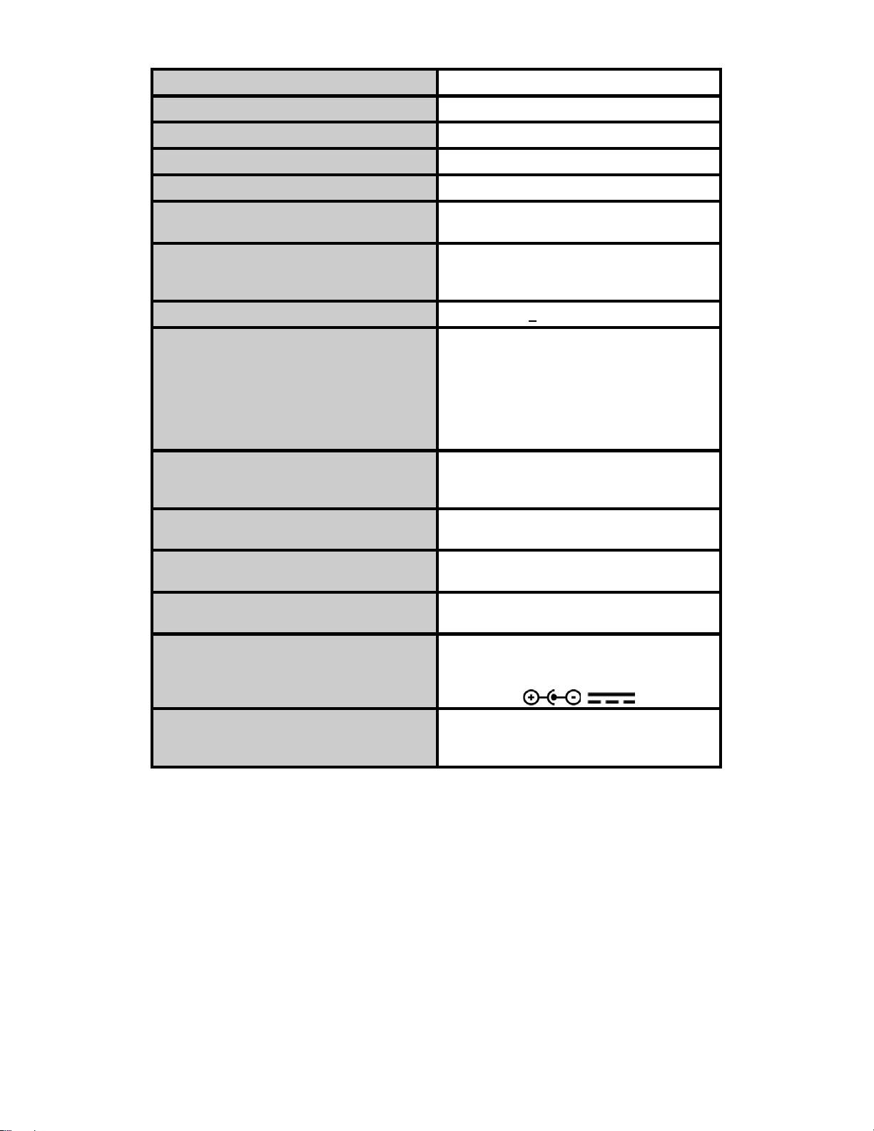
DISPLAY
SETUP MEMORY
MEMORY RETENTION
OPERATING RANGE
STORAGE RANGE
CONSTRUCTION
SIZE
WEIGHT
CONNECTIONS
PRESSURE MEDIA
POWER
Any pure fluid or gas that is compatible with
Pyrex, Glass, Silicon, Alumina Ceramic,
Epoxy, RTV, gold, aluminum and nickel.
POWER CONSUMPTION
BATTERY LIFE
BATTERY ELIMINATOR
(OPTIONAL)
ANALOG OUTPUT
(OPTIONAL)
DC -- Output dependent on Digital Filter
P:\MANUALS\BCGroup\…\DPM-2000\DPM2300_UM_Rev03.doc
LCD Graphical 128 X 64 Pixels
EEPROM, All Parameters
10 Years w/o Power
15 to 30 Degrees C
-40 to 60 Degrees C
Enclosure - ABS Plastic
Face - Lexan, Back Printed
7.09 x 3.94 x 1.56 inches
180 x 100 x 40 mm
(HxWxD)
<
1 lbs. (0.45 kg)
Power - 2.1 mm Center Negative
RS232 - 7 pin Mini Din
Pressure - .3/5/10 Male Luer
75/100 CPC
Coupler or Insert
Temperature - 1/4 inch phone
Analog Output - BNC
LINE: 9VDC, Center Negative
BATTERY
ON: less than 18 mA
OFF: less than 40 µA
CONTINUOUS: ~80 hrs.
BC20 - 21100 -- US
BC20 - 21101 -- Euro
1.0 to 4.0 VDC FS, selectable
: 9V Alkaline
OFF: 12 months
9V, 200 mA DC
+/- .1% FS
31
Page 34

NOTES
32
Page 35

33
 Loading...