

Page 1
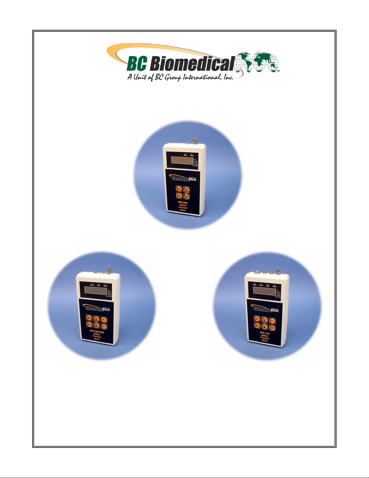
DIGITAL PRESSURE METERS
DPM-2001
DPM-2001PLUS DPM-2100
USER MANUAL
Page 2

BC BIOMEDICAL
DPM-2001/2001 PLUS/2100
TABLE OF CONTENTS
DESCRIPTION............................................................................................................. 3
SYSTEM INDICATORS .............................................................................................. 5
KEYS:
DPM-2001 .......................................................................................................... 6
DPM-2001 PLUS................................................................................................ 8
DPM-2100 .......................................................................................................... 10
SETUP MODE ............................................................................................................. 12
INPUTS ........................................................................................................................ 13
STATUS DISPLAYS..................................................................................................... 14
COMMUNICATIONS.................................................................................................... 15
MANUAL REVISIONS.................................................................................................. 20
WARRANTY................................................................................................................. 20
SPECIFICATIONS ....................................................................................................... 21
DRAWINGS
DPM-2001 PHYSICAL DIAGRAM.................................................................... 23
DPM-2001 PLUS PHYSICAL DIAGRAM ......................................................... 24
DPM-2100 PHYSICAL DIAGRAM.................................................................... 25
NOTES......................................................................................................................... 26
1
Page 3

iii
N O T I C E
iii
BC GROUP INTERNATIONAL, INC. RESERVES THE RIGHT TO MAKE
CHANGES TO ITS PRODUCTS OR SPECIFICATIONS AT ANY TIME,
WITHOUT NOTICE, IN ORDER TO IMPROVE THE DESIGN OR
PERFORMANCE AND TO SUPPLY THE BEST POSSIBLE PRODUCT. THE
INFORMATION IN THIS MANUAL HAS BEEN CAREFULLY CHECKED AND
IS BELIEVED TO BE ACCURATE. HOWEVER, NO RESPONSIBILITY IS
ASSUMED FOR INACCURACIES.
Manual DPM-2001, 2001 PLUS, 2100 Copyright © 2004
www.bcgroupintl.com MADE IN THE USA
10/04 Rev 06
2
Page 4

BC GROUP
DPM-2001/2001 PLUS/2100
DIGITAL PRESSURE METERS
The Model DPM-2001 Series is a Microprocessor based Digital Pressure Meter family.
They measure both gas and liquid pressures and provide multiple engineering unit displays
for the results. The DPM-2100 Series adds temperature measurement. The following are
highlights of some of the main features.
DPM-2001:
• -13.50 TO 100.00 PSI RANGE
• 0.1% FS ACCURACY (Pressure)
• PRESSURE SCALES INCLUDE PSI, inH
• DIGITAL CALIBRATION – NO POTS TO TURN
• 5 DIGIT LCD PLUS SCALE INDICATION
• BATTERY LIFE DISPLAY (0 to 100%)
• PROGRAMMABLE DIGITAL FILTER
• LCD CONTRAST IS SOFTWARE ADJUSTABLE
• 16 BIT PRESSURE MEASUREMENT
• DIGITAL ZERO ADJUST
DPM-2001 PLUS:
Includes all the features of the DPM-2001 and:
• MAX and MIN PRESSURE VALUE STORAGE
• RS232 SERIAL COMMUNICATIONS
DPM-2100:
Includes all the features of the DPM-2001 and:
O, cmH2O, AND mmHg
2
• MAX and MIN PRESSURE VALUE STORAGE
• RS232 SERIAL COMMUNICATIONS
• YSI 700 TEMPERATURE PROBE INTERFACE
• 0.0-100.0 C / 32.0-212.0 F TEMPERATURE RANGE
• 0.5% FS ACCURACY (Temperature)
• MAX and MIN TEMPERATURE VALUE STORAGE
3
Page 5

OPTIONAL ACCESSORIES:
• BE2000PU 120 VAC BATTERY ELIMINATOR, U.S.
• BE2000PE 220 VAC BATTERY ELIMINATOR, EUROPE
• DPM2000C RS-232 CABLE
• BC20-01004 HARD CARRYING CASE
• BC20-01005 UNIVERSAL PRESSURE ADAPTER KIT
4
Page 6

SYSTEM INDICATORS
Four indicators are provided to identify the Current Operating Mode.
PRESSURE SCALE – The pressure scale is indicated by an identifier bar. The RANGE
key will toggle the pressure units among PSI, mmHG, inH2O and cmH2O. The following is
a breakdown of the available pressure scales and the measurement range for each scale:
Identifier Bar Pressure Units Pressure Range
PSIG -13.50 to 100.00
mmHg -701 to 5190
inH2O -374 to 2773
bar
no bar
(flashing)
cmH2O -951 to 7043
NOTE: If the measured pressure is outside of the range of the instrument, the display will
display -HI- or -Lo-.
NOTE: InH20, cmH20 and mmHg ranges are calibrated for 20 degrees Celsius.
TEMPERATURE SCALE (MODEL DPM-2100 ONLY) – The temperature can be displayed
in either degrees Celsius or Fahrenheit. When temperature is displayed, the RANGE key
will toggle the temperature units between Fahrenheit and Celsius.
Temperature Units Temperature Range
Degrees C 0.0 to 100.0
Degrees F 32.0 to 212.0
NOTE: If the measured temperature is outside of the range of the instrument, the display
will display -HI- or -Lo-. If a probe is not connected, the display will show “no probe”.
LOW BATTERY – When the battery life reaches 10 percent, the display will show the
message “lo bat” once every minute.
LINE POWER – When meter is running from the optional Battery Eliminator (BE2000PU,
BE2000PE), the display will show “Line” instead of the battery life remaining.
5
Page 7
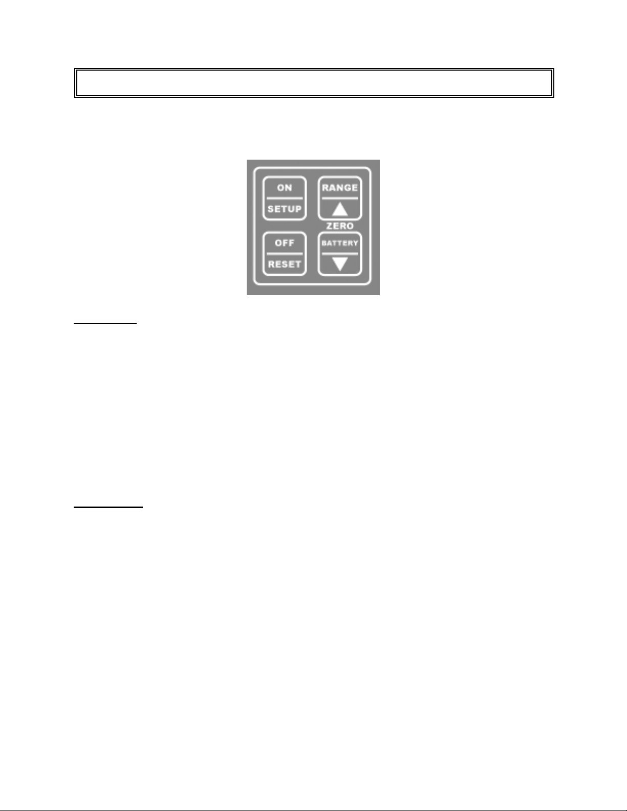
KEYS – DPM-2001
Four tactile-touch keys are provided for system operation.
ON/SETUP – The function of this key is dependant on the Current Operating Mode as
follows:
POWER OFF – If this key is pressed while the power is turned OFF, the power will
be turned ON
PRESSURE MEASUREMENT – If this key is pressed while the pressure is being
displayed, the Setup Mode will be entered.
SETUP MODE – Pressing this key while in the Setup Mode will sequence the
display through the available parameters.
OFF/RESET – The function of this key is dependant on the Current Operating Mode as
follows:
PRESSURE MEASUREMENT – If this key is pressed while the pressure is being
displayed, the power will be turned OFF
SETUP MODE – Pressing this key while in the Setup Mode will exit the Setup Mode
and automatically save all settings.
6
Page 8

RANGE/UP – The function of this key is dependant on the Current Operating Mode as
follows:
PRESSURE MEASUREMENT – If this key is pressed while the pressure is being
displayed, the unit will step through the available pressure ranges (PSI,
inH20, cmH20 and mmHg).
SETUP MODE – If this key is pressed in the Setup Mode, the value of the displayed
setting will increment. Pressing and holding this key will cause the rapid
automatic incrementing of the displayed setting.
BATTERY/DOWN – The function of this key is dependant on the Current Operating Mode
as follows:
PRESSURE MEASUREMENT – If this key is pressed while the pressure is being
displayed, the unit will display the percent (0 to 100) of battery life remaining.
NOTE: If the optional wall mount power supply is used, the unit will display
“Line”.
SETUP MODE – If this key is pressed in the Setup Mode, the value of the displayed
setting will decrement. Pressing and holding this key will cause the rapid
automatic decrementing of the displayed setting.
ZERO – This function is a combination of two keys (RANGE/UP and BATTERY/DOWN).
If both keys are depressed and held for 5 seconds, the pressure display will be zeroed.
NOTE: If the BATTERY/DOWN key is depressed first, it will prevent the range from
being changed in the process.
7
Page 9
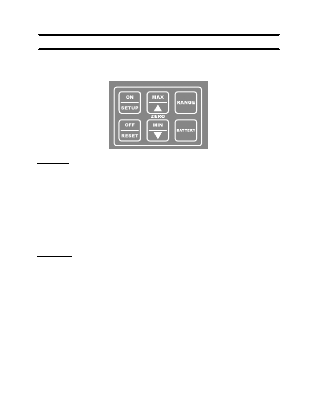
KEYS – DPM-2001 PLUS
Six tactile-touch keys are provided for system operation.
ON/SETUP – The function of this key is dependant on the Current Operating Mode as
follows:
POWER OFF – If this key is pressed while the power is turned OFF, the power will
be turned ON
PRESSURE MEASUREMENT – If this key is pressed while the pressure is being
displayed, the Setup Mode will be entered.
SETUP MODE – Pressing this key while in the Setup Mode will sequence the
display through the available parameters.
OFF/RESET – The function of this key is dependant on the Current Operating Mode as
follows:
PRESSURE MEASUREMENT – If this key is pressed while the pressure is being
displayed, the power will be turned OFF
SETUP MODE – Pressing this key while in the Setup Mode will exit the Setup Mode
and automatically save all settings.
MIN/MAX MODE – Pressing this key when a Min or Max Value is being displayed
(MIN or MAX key is held down) will cause that value in that capture register
to be reset to the current reading.
8
Page 10

MAX/UP – The function of this key is dependant on the Current Operating Mode as follows:
PRESSURE MEASUREMENT – If this key is pressed while the pressure is being
displayed, the unit will display the maximum pressure detected since the
capture register was last reset.
SETUP MODE – If this key is pressed in the Setup Mode, the value of the displayed
setting will increment. Pressing and holding this key will cause the rapid
automatic incrementing of the displayed setting.
MIN/DOWN – The function of this key is dependant on the Current Operating Mode as
follows:
PRESSURE MEASUREMENT – If this key is pressed while the pressure is being
displayed, the unit will display the minimum pressure detected since the
capture register was last reset.
SETUP MODE – If this key is pressed in the Setup Mode, the value of the displayed
setting will decrement. Pressing and holding this key will cause the rapid
automatic decrementing of the displayed setting.
ZERO – This function is a combination of two keys (MAX/UP and MIN/DOWN). If both
keys are depressed and held for 5 seconds, the pressure display will be zeroed.
RANGE – The function of this key is to select the desired display engineering units. When
viewing pressure it will sequence through the four ranges (PSI, inH20, cmH20 and mmHg).
BATTERY - If this key is pressed while the pressure is being displayed, the unit will display
the percent (0 to 100) of battery life remaining.
NOTE: If the optional Battery Eliminator is used, the unit will display “Line”.
9
Page 11

KEYS – DPM-2100
Six tactile-touch keys are provided for system operation.
ON/SETUP – The function of this key is dependant on the Current Operating Mode as
follows:
POWER OFF – If this key is pressed while the power is turned OFF, the power will
be turned ON
PRESSURE MEASUREMENT – If this key is pressed while the pressure is being
displayed, the Setup Mode will be entered.
SETUP MODE – Pressing this key while in the Setup Mode will sequence the
display through the available parameters.
OFF/RESET – The function of this key is dependant on the Current Operating Mode as
follows:
PRESSURE MEASUREMENT – If this key is pressed while the pressure or
temperature is being displayed, the power will be turned OFF
SETUP MODE – Pressing this key while in the Setup Mode will exit the Setup Mode
and automatically save all settings.
MIN/MAX MODE – Pressing this key when a Min or Max Value is being displayed
(MIN or MAX key is held down) will cause that value in that capture register
to be reset to the current reading.
10
Page 12

MAX/UP – The function of this key is dependant on the Current Operating Mode as follows:
PRESSURE MEASUREMENT – If this key is pressed while the pressure is being
displayed, the unit will display the maximum pressure detected since the
capture register was last reset.
TEMPERATURE MEASUREMENT – If this key is pressed while the temperature is
being displayed, the unit will display the maximum temperature detected
since the capture register was last reset.
SETUP MODE – If this key is pressed in the Setup Mode, the value of the displayed
setting will increment. Pressing and holding this key will cause the rapid
automatic incrementing of the displayed setting.
MIN/DOWN – The function of this key is dependant on the Current Operating Mode as
follows:
PRESSURE MEASUREMENT – If this key is pressed while the pressure is being
displayed, the unit will display the minimum pressure detected since the
capture register was last reset.
TEMPERATURE MEASUREMENT – If this key is pressed while the temperature is
being displayed, the unit will display the minimum temperature detected since
the capture register was last reset.
SETUP MODE – If this key is pressed in the Setup Mode, the value of the displayed
setting will decrement. Pressing and holding this key will cause the rapid
automatic decrementing of the displayed setting.
ZERO – This function is a combination of two keys (MAX/UP and MIN/DOWN). If both
keys are depressed and held for 5 seconds, the pressure display will be zeroed.
RANGE – The function of this key is to select the desired display engineering units. When
viewing pressure it will sequence through the four ranges (PSI, inH20, cmH20 and mmHg).
When viewing temperature, it will toggle between Centigrade and Fahrenheit.
PRES/TEMP – The function of this key is to toggle between pressure and temperature
displays.
11
Page 13

SETUP MODE
The Setup Mode allows the user to adjust the configuration of the meter. The Setup Mode
is entered by pressing The ON/SETUP key when the unit is on. The parameter and the
current value will alternately flash in the display. The following table indicates the
Parameters that are available, their meaning and available setting range:
PARAMETER DESCRIPTION RANGE
BAT REMAINING BATTERY LIFE 0 - 100 %
CONT CONTRAST 0 - 15
AOFF AUTO OFF TIMER 0 - 30 MINUTES
BEEP KEY BEEP LENGTH 0 - 15
FCON DIGITAL FILTER CONSTANT 1 - 255
BAT – (MODEL 2100 ONLY) This parameter gives an indication of the remaining battery
power. The battery life is displayed as percent of life.
CONT – This parameter controls the contrast of the LCD display. A Higher setting will
cause the display to darken. A lower setting will cause the display to lighten.
AOFF – This parameter determines the period of inactivity before the meter is turned OFF.
A timer is started when the meter is turned ON and is reset each time a key is pressed.
When the timer reaches the value set in this parameter, the power is automatically turned
OFF.
NOTE: Setting this parameter to 0 disables the Auto Off timer. When running from
line power, the meter will not automatically shut off.
BEEP – This parameter controls the length of the audio feedback beep (click) that occurs
when a key is depressed. A Higher setting will cause a longer (louder) beep. If the value is
set to 0, the beep is eliminated.
FCON – This parameter controls the Filter Constant. The software has a Digital Filter that
averages the pressure readings to produce a stable display. This setting determines the
number of samples that are averaged in the digital filter. Increasing this setting will cause a
more stable display. However, it will also cause a slower response to small changes in
pressure. The best setting is the smallest number that provides a stable display.
12
Page 14

INPUTS
PRESSURE INPUT – Male luer lock connector is used for the pressure input.
POWER INPUT – A 2.1 mm jack is provided for the optional 9 VDC Battery Eliminator
power supply that may be used for continuous run applications. It bypasses the internal
battery when plugged in.
RS232 – This is the serial interface connector. (MODELS 2001 PLUS AND 2100 ONLY)
TEMPERATURE INPUT – A ¼” phono jack is provided to accept any standard YSI Series
700 Temperature Probe. (MODEL 2100 ONLY)
13
Page 15

STATUS DISPLAYS
LOW BAT – This status screen displays when the battery reaches a critical low level. LOW
BAT is displayed for two seconds once a minute until the battery is replaced.
DEF CAL – This status screen displays on Power Up if the unit is out of Calibration. The
unit will load default values. The unit should be returned to the Factory for Calibration.
14
Page 16

COMMUNICATIONS
Since the meter does not handle a great deal of data, the link has been optimized to allow
the user, through very simple instructions, to control and interrogate the meter. NOTE:
RS232 is only available on DPM-2001 Plus and DPM-2100 models.
Use RS232 Cable P/N DPM2000C to connect from the RS232 connector on the top of the
DPM to a DB9 Com Port connector on a PC. The DPM is configured as Data
Communications Equipment (DCE) and is intended to connect directly to Data Terminal
Equipment (DTE). This is the standard direct connection to a PC.
The Link communicates at a fixed 115,200 baud with 8 bit data, 1 stop bit, 1 start bit, no
parity and no handshaking.
The following section describes the JPC Protocol used by the meter.
The JPC Protocol consists of 6 basic commands:
R - READ
W - WRITE
U - UPLOAD
Q - QUICKSEND
V - VERSION
X - CANCEL
The data format is standard ASCII and all data are BCD values.
The following is a breakdown of each of the commands and the way they are accessed.
The meter will echo all characters that are typed to it. When used with a terminal, this will
provide the appropriate display. When used with a computer system, this will provide direct
feedback of the fact that unit has accepted the data.
All commands are completed with a carriage return from the computer. All commands will
be acknowledged by a carriage return, line feed ($0D,$0A). If a command is not valid, the
meter will respond with “??”. All commands are not case sensitive.
15
Page 17

READ/WRITE COMMANDS
The READ command is utilized to read from the meter any of the gathered data. The
command is entered as a letter followed by 2 numbers, followed by a carriage return:
R(Location)(Return)
The 'R' indicates to the meter that the command is to be a READ command.
The Location contains two digits that indicate the data location that is to be read.
The carriage return indicates that the command is to be activated.
The WRITE command allows the user to update the system settings. The write command
is entered as a letter followed by 7 numbers, followed by a carriage return.
W(Location)(Data) (Return)
The 'W' indicates to the meter that the command is to be a WRITE command.
The Location contains two digits that indicate the data location that is to be read.
The Data contains five digits that indicate the data that is to be written at the desired
Location.
The carriage return indicates that the command is to be activated.
16
Page 18

LOCATION ACCESS DESCRIPTION RANGE
01
02 R/W CONTRAST 0-15
03
04
05
06
07
08
09 R RESERVED 0-65535
10 R MODEL
11 R PRESSURE See Note 1
12 R MAX PRESSURE See Note 1
13 R MIN PRESSURE See Note 1
R
R/W
R
R
R
R
R/W
% BATTERY LIFE
REMAINING
AUTO POWER OFF
RESERVED
RESERVED
RESERVED
RESERVED
FILTER CONSTANT
0-65535
0-65535
0-65535
0-65535
0 = DPM-2001
1 = DPM-2001+
2 = DPM-2100
0-100
0-30
0-255
14 R TEMPERATURE See Note 1
15 R MAX TEMPERATURE See Note 2
16 R MIN TEMPERATURE See Note 2
0=PSI
17 R/W PRESSURE UNITS
18 R/W TEMPERATURE UNITS
1=mmHg
2=inH2O
3=cmH20
0=Celsius
1=Fahrenheit
Note 1 – The units for the pressure data is determined by the setting in Location 17. This may be set via the
Write command or manually using the Range Key. See Specifications Page for Ranges.
Note 2 – The units for the temperature data is determined by the setting in Location 18. This may be set via
the Write command or manually using the Range Key. See Specifications Page for Ranges.
The following is an example of how the Read/Write commands are used. For display
purposes, the symbol <cr> will be used to identify a carriage return ($0D), and the symbol
<lf> will be used to identify a line feed ($0A).
Data Sent Data Returned Meaning
R03<cr> R03<cr><lf> Echo of Command Sent
00010<cr><lf> Auto Off is set to 10 minutes
W0300000<cr> W0300000<cr><lf> Echo of Command Sent
Change Auto off to disabled
17
Page 19

The Upload command allows the user to read all of the selected device data from locations
1 through 18 with a single command. The data will be transmitted as a single block with
each location separated by a carriage return, linefeed ($0D,$0A).
The following is the format for this command:
See the table in the Read Command section for details on the data structure.
Quicksend is a feature that allows the user to receive an automatic update of all of the
meter data without any user interaction. When the Quicksend feature is turned ON, the
meter will automatically send all of the device data every half second. The Quicksend
feature is toggled ON and OFF with the Quicksend command.
The following is the format for the 'Q' command:
See the table in the Read Command section for details on the data structure.
UPLOAD COMMAND
U (Return)
QUICKSEND COMMAND
Q (RETURN)
18
Page 20

The Version command allows the user to read the Software Version that the unit is running.
To read the Version, the following syntax is used:
The CANCEL command is simply a way to re-establish proper control, should an error
occur or an incorrect command be transmitted. For the most part, an incorrect command
will simply be ignored and the meter will prepare for an additional command. However, a
command may be cancelled midstream by transmitting an 'X' (ASCII). This command does
not require a carriage return, nor will it acknowledge with a carriage return. However, it will
echo an 'X' to indicate that the CANCEL command has been received.
The command may also be utilized as a clear and/or acknowledgement of the meter being
on line.
VERSION COMMAND
V (RETURN)
CANCEL COMMAND
19
Page 21

A
MANUAL REVISIONS
Revision # Program # Revisions Made
Rev 01 DT7325CA Preliminary Manual
Rev 02 DT7325CA Editing/Drawing Updates
Rev 03 DT7325CA Battery Eliminator
Rev 04 DT7325CB Status Displays
Rev 05 DT7325CD Accuracy Upgrades
Rev 06 DT7325CG Program Upgrades, Color Overlays
LIMITED WARRANTY
WARRANTY
FROM DEFECTS IN MATERIALS AND WORKMANSHIP UNDER THE SERVICE FOR WHICH THEY
RE INTENDED. THIS WARRANTY IS EFFECTIVE FOR TWELVE MONTHS FROM THE DATE OF
SHIPMENT.
EXCLUSIONS: THIS WARRANTY IS IN LIEU OF ANY OTHER WARRANTY EXPRESSED OR
IMPLIED, INCLUDING, BUT NOT LIMITED TO ANY IMPLIED WARRANTY OF MERCHANTABILITY
OR FITNESS FOR A PARTICULAR PURPOSE.
BC GROUP INTERNATIONAL, INC. IS NOT LIABLE FOR ANY INCIDENTAL OR CONSEQUENTIAL
DAMAGES.
NO PERSON OTHER THAN AN OFFICER IS AUTHORIZED TO GIVE ANY OTHER WARRANTY OR
ASSUME ANY LIABILITY.
REMEDIES: THE PURCHASER'S SOLE AND EXCLUSIVE REMEDY SHALL BE: (1) THE REPAIR OR
REPLACEMENT OF DEFECTIVE PARTS OR PRODUCTS, WITHOUT CHARGE. (2) AT THE OPTION
OF BC GROUP INTERNATIONAL, INC., THE REFUND OF THE PURCHASE PRICE.
: BC GROUP INTERNATIONAL, INC. WARRANTS ITS NEW PRODUCTS TO BE FREE
20
Page 22

SPECIFICATIONS
DPM-2001/DPM-2001 PLUS/DPM-2100
DIGITAL PRESSURE METERS
PRESSURE RANGE -13.50 to 100.00 PSI
-701 to 5190 mmHg @ 20C
-374 to 2773 inH2O @ 20C
-951 to 7043 cmH2O @ 20C
PRESSURE RESOLUTION 0.01 PSI
1 inH2O
1 cmH2O
1 mmHg
PRESSURE ACCURACY +/- 0.1% FS
TEMPERATURE RANGE 0.0 to 100.0 °C
(DPM-2100 MODELS ONLY) 32.0 to 212.0 °F
TEMPERATURE RESOLUTION 0.1 °C
0.1 °F
TEMPERATURE ACCURACY +/- 0.5% FS
DISPLAY Six, 0.35 Inch High, Seven
Segment, LCD Uniplanar digits.
SETUP MEMORY EEPROM, All Parameters
MEMORY RETENTION 10 Years w/o Power
OPERATING RANGE 0 to 50 Degrees C
STORAGE RANGE -40 to 60 Degrees C
CONSTRUCTION Enclosure – ABS Plastic.
Face – Lexan, Back Printed
21
Page 23

SIZE 7.09 x 3.94 x 1.56 inches
180 x 100 x 40 mm
(HxWxD)
WEIGHT < 1 lbs. (0.45 kg)
CONNECTIONS Power – 2.1mm Center Negative
RS-232 – 1/8 inch phono
Pressure – Male Luer
Temperature – 1/4 inch phono
TEMPERATURE SENSOR Directly compatible with all YSI
Series 700 Temperature Probes
or equivalent
PRESSURE MEDIA Any pure fluid or gas that is
compatible with Pyrex, Glass,
Silicon, Alumina Ceramic, Epoxy,
RTV, gold, aluminum, and nickel.
POWER LINE: 9VDC, Center Negative
BATTERY: 9V Alkaline
POWER CONSUMPTION ON: less than 6mA
OFF: less than 20µA
BATTERY LIFE CONTINUOUS: 80 hrs.
OFF: 12 months
BATTERY ELIMINATOR BE2000PU (120 VAC) - US
(Optional) BE2000PE (220 VAC) – Euro
9V, 50 mA DC
P:\MANUALS\BCGroup\…\DPM2000_60-7325C0-00_UM_Rev06.doc
22
Page 24

23 24 25 26
Page 25

Page 26

Page 27

NOTES
 Loading...