

Page 1
DEFIBRILLATOR
ANALYZERS
DA-2006
DA-2006P
ANALYZER
W/ PACER
USER MANUAL
Page 2

Page 3

BC BIOMEDICAL
DA-2006 SERIES
TABLE OF CONTENTS
WARNINGS ................................................................................................................. 2
DESCRIPTION............................................................................................................. 5
OVERVIEW.................................................................................................................. 13
DEFIBRILLATOR ANALYZER ..................................................................................... 21
MAIN SCREEN.................................................................................................. 21
ECG WAVEFORMS SCREEN .......................................................................... 27
PLAYBACK LAST PULSE SCREEN ................................................................. 31
START CHARGE TIMER SCREEN .................................................................. 33
PRINT HEADER................................................................................................ 35
SELF TEST WAVEFORM ................................................................................. 37
RUNNING A DEFIBRILLATION TEST .............................................................. 39
INTRODUCTION .................................................................................... 39
DIFIBRILLATION TEST .......................................................................... 41
CARDIOVERSION TEST........................................................................ 45
CHARGE TIME TEST............................................................................. 49
SHOCK ADVISORY ALGORITHM TEST ............................................... 51
TRANSCUTANEOUS PACEMAKER ANALYZER ....................................................... 53
PACE MAIN SCREEN ...................................................................................... 53
PACER MODE SETUP SCREEN...................................................................... 59
SENSITIVITY TEST .......................................................................................... 61
REFRACTORY PERIOD TEST ......................................................................... 63
PRINT MENU SCREEN .................................................................................... 65
MANUAL REVISIONS.................................................................................................. 67
WARRANTY................................................................................................................. 67
SPECIFICATIONS ....................................................................................................... 69
NOTES......................................................................................................................... 75
1
Page 4

The DA-2006 and DA-2006P are intended for
testing only and they should never be used in
diagnostics, treatment or any other capacity
where they would come in contact with a patient.
All connections to patients must be removed
before connecting the Device Under Test (DUT)
to the Analyzer. A serious hazard may occur if
The DA-2006 and DA-2006P
skilled technical personnel only.
WARNING
are for use by
WARNING
WARNING
the patient is connected when testing
with the Analyzer.
Do not connect any leads from the patient
directly to the Analyzer or DUT.
2
Page 5

NOTICE
BC GROUP INTERNATIONAL, INC. RESERVES THE RIGHT TO MAKE
CHANGES TO ITS PRODUCTS OR SPECIFICATIONS AT ANY TIME,
WITHOUT NOTICE, IN ORDER TO IMPROVE THE DESIGN OR
PERFORMANCE AND TO SUPPLY THE BEST POSSIBLE PRODUCT. THE
INFORMATION IN THIS MANUAL HAS BEEN CAREFULLY CHECKED
AND IS BELIEVED TO BE ACCURATE. HOWEVER, NO RESPONSIBILITY
IS ASSUMED FOR INACCURACIES.
CONTACT INFORMATION
BC BIOMEDICAL
BC GROUP INTERNATIONAL, INC.
PO BOX 25125
9415 GENTRY AVE
ST. LOUIS, MO 63125
USA
1-800-242-8428
314-638-3800
www.bcgroupintl.com
sales@bcgroupintl.com
Manual DA-2006 Series Copyright © 2006
www.bcgroupintl.com Made in the USA
7/06 Rev 04
3
Page 6

This page intentionally left blank.
4
Page 7

BC GROUP
DA-2006 SERIES
DEFIBRILLATOR ANALYZER
The Model DA-2006 Series is a microprocessor-based instrument family that is used in the
testing of defibrillators. They measure the energy output and provided information about
the pulse. They are used on manual, semi-automatic and automatic defibrillators with
monophasic or biphasic outputs.
The DA-2006P model additionally provides a Transcutaneous Pacemaker analysis function.
It measures and displays pacer pulse information as well as performing Refractory Period,
Sensitivity and Immunity testing.
All models have a built in 50 ohm human body simulation load as well as 12 lead ECG with
arrhythmias and performance waveforms. Additionally, they have a Centronics printer port,
a serial port, oscilloscope output, high level ECG output, as well as provision for a battery
eliminator.
The DA-2006 Series makes viewing and selecting the desired waveforms and test data
quick and intuitive, with all operational information being available on the 240 by 64 pixel
graphic display, allowing for easy maneuvering through parameters and scrolling through
available options.
NOTE: The instrument is intended for use by trained service technicians.
5
Page 8

DA-2006
The following are highlights of some of the main features:
GENERAL
• SIMPLE TO OPERATE
• GRAPHICS DISPLAY WITH SIMULTANEOUS DETAILED STATUS OF
PARAMETERS AND SCROLLING CONTROL OF OPTIONS
• ON SCREEN VIEWING OF DEFIBRILLATOR WAVEFORM
• DROP DOWN CHOICE SCREENS LIST ALL OPTIONS FOR PARAMETERS
• MONOPHASIC AND BIPHASIC COMPATABLE
• 5000 V, 1000 JOULE CAPACITY
• HIGH AND LOW RANGES
• CARDIOVERSION DELAY MEASURMENT
• CHARGE TIME MEASUREMENT
• WAVEFORM STORAGE AND PLAYBACK
• 10 UNIVERSAL PATIENT LEAD CONNECTORS
• 25 PIN CONNECTOR FOR CENTRONICS PRINTER
• 9 VOLT BATTERY POWER
• LOW BATTERY INDICATOR
• AVAILABLE BATTERY ELIMINATOR
• DISPLAY BACKLIGHT
• FULL REMOTE OPERATION VIA RS-232
• FLASH PROGRAMMABLE FOR UPGRADES
PACEMAKER OPTION
• 26 SELECTABLE INTERNAL LOADS
• FULL PULSE ANALYSIS
• DEMAND SENSITIVITY TEST
• REFRACTORY PERIOD TESTS
• 50/60 Hz INTERFERENCE TEST SIGNALS
6
Page 9

Description
ENERGY OUTPUT MEASUREMENT GENERAL
The unit measures the energy in the output pulse of both monophasic and biphasic
defibrillators.
• PULSE TYPE: Monophasic or Biphasic
• LOAD RESISTANCE: 50 Ohms +/- 1%, non-inductive (<1 µH)
• DISPLAY RESOLUTION: 0.1 Joules
• MEASUREMENT TIME WINDOW: 100 ms
• ABSOLUTE MAX PEAK VOLTAGE: 6000 Volts
• CARDIOVERSION DELAY: 0 to 6000 ms
• CARDIOVERSION RESOLUTION: 0.1 ms
ENERGY OUTPUT MEASUREMENT HIGH RANGE
The high range allows for a large pulse with high voltage and current.
• VOLTAGE: <5000 Volts
• MAX CURRENT: 120 Amps
• MAX ENERGY: 1000 Joules
• TRIGGER LEVEL: 100 Volts
• PLAYBACK AMPLITUDE: 1 mv / 1000 V Lead I
• TEST PULSE: 125 Joules +/- 20%
ENERGY OUTPUT MEASUREMENT LOW RANGE
The low range allows greater resolution on smaller pulses.
• VOLTAGE: <1000 Volts
• MAX CURRENT: 24 Amps
• MAX ENERGY: 50 Joules
• TRIGGER LEVEL: 20 Volts
• PLAYBACK AMPLITUDE: 1 mv / 1000 V Lead I
• TEST PULSE: 5 Joules +/- 20%
7
Page 10

DA-2006
ENERGY OUTPUT MEASUREMENT OTHER
OSCILLIOSCOPE OUTPUT
• HIGH MEASURE RANGE: 1000:1 amplitude-attenuated
• LOW MEASURE RANGE: 200:1 amplitude-attenuated
WAVEFORM PLAYBACK
• OUTPUT – LEAD 1 & PLATES
• GRAPHICS SCREEN
• 200:1 Time Base Expansion
SYNC TIME MEASUREMENTS
• TIMING WINDOW: Starts 40 ms before each R-wave peak
• TEST WAVEFORMS: All waveform simulations available
CHARGE TIME MEASUREMENT
• From 0 .1 to 99.9 sec
ECG FUNCTIONS
The unit can produce a wide variety of ECG simulations. The user simply selects the
parameters that match the desired output.
• RATE: 30,40,45,60,80,90,100,120,140,160,180,200,220,240,260,280,300 BPM
• AMPLITUDE: 0.50,1.0,1.5,2.0 mV (Lead II)
ECG-PERFORMANCE FUNCTIONS
The unit can generate Sine, Square, Triangular, and Pulse waveforms with adjustable
amplitudes for performance testing.
• SINE: 0.1,0.2,0.5,5,10,40,50,60,100 Hz
• SQUARE: 0.125,2 Hz
• TRIANGLE: 2,2.5 Hz
• PULSE: 30,60,120 BPM; 60 ms WIDTH
• AMPLITUDE: 0.5,1.0,1.5,2.0 mV (Lead II)
8
Page 11

Description
ARRHYTHMIA FUNCTIONS
The unit can simulate 12 different arrhythmias.
• VENTRICULAR FIBRILLATION
• ATRIAL FIBRILLATION
• SECOND DEGREE A-V BLOCK
• RIGHT BUNDLE BRANCH BLOCK
• PREMATURE ATRIAL CONTRACTION
• EARLY PVC
• STANDARD PVC
• R ON T PVC
• MULTIFOCAL PVC
• BIGEMINY
• RUN OF 5 PVC
• VENTRICULAR TACHYCARDIA
SHOCK ADVISORY TESTS
The unit can simulate 8 different waveforms to test the shock algorithm of advanced
defibrillators:
• ASYSTOLE
• COARSE VENTRICULAR FIBRILLATION
• FINE VENTRICULAR FIBRILLATION
• MULTIFOCAL VENTRICULAR TACHYCARDIA @ 140 BPM
• MULTIFOCAL VENTRICULAR TACHYCARDIA @ 160 BPM
• POLYFOCAL VENTRICULAR TACHYCARDIA @ 140 BPM
• POLYFOCAL VENTRICULAR TACHYCARDIA @ 160 BPM
• SUPRAVENTRICULAR TACHYCARDIA @ 90 BPM
9
Page 12

DA-2006
TRANSCUTANEOUS PACER ANALYZER
The unit can test external transcutaneous pacemakers. It has a wide variety of loads and
can measure the Pacer Pulse, Demand Sensitivity and Refractory Periods (Pacing and
Sensing):
• LOAD:
• RANGE: 50,100,150,200,300,400,500,600,700,800,900,1000,1100,
1200,1300,1400,1500,1600,1700,1800,1900,2000,2100,
2200,2300 Ohms
• PULSE:
• AMPLITUDE: 4 TO 300 mA (100 Ohm load)
• RATE: 30 TO 800 ppm
• WIDTH: 0.6 to 80 ms
• DEMAND SENSITIVITY:
• WAVEFORMS:
• SELECTIONS: SQUARE, TRIANGLE, HAVERSINE
• WIDTH: 10,25,40,100,200 ms
• ECG:
• AMPLITUDE – OUT: 0 to 4 mv
• PACER INPUT (50 TO 400 OHMS):
• AMPLITUDE – OUT: 0 to 10 mv / 50 Ohms
• RATE – IN: 30 to 120 ppm
• PACER INPUT (500 TO 2300 OHMS & OPEN):
• AMPLITUDE – OUT: 0 to 100 mv
• RATE – IN: 30 to 120 ppm
• DEFIBRILLATOR PLATES:
• AMPLITUDE – OUT: 0 to 10 mv
• RATE – IN: 30 to 120 ppm
• REFRACTORY PERIOD:
• PACING: 20 to 500 ms
• SENSING: 20 to 500 ms
• 50/60 HZ INTERFERENCE TEST SIGNAL:
• ECG OUTPUT: 0,0.4,0.8,1.2,1.6,2.0,2.4,2.8,3.2,3.6,4.0 mv
• PACER INPUT 50 OHMS: 0,1,2,3,4,5,6,7,8,9,10 mv
• PACER INPUT 100 OHMS: 0,2,4,6,8,10,12,14,16,18,20 mv
• PACER INPUT 150 OHMS: 0,3,6,9,12,15,18,21,24,27,30 mv
• PACER INPUT 200 OHMS: 0,4,8,12,16,20,24,28,32,26,40 mv
• PACER INPUT 300 OHMS: 0,6,12,18,24,30,36,42,48,54,60 mv
• PACER INPUT 400 OHMS: 0,8,16,24,32,40,48,56,64,72,80 mv
• PACER INPUT > 500 OHMS: 0,10,20,30,40,50,60,70,80,90,100 mv
• DEFIBRILLATOR PLATES: 0,1,2,3,4,5,6,7,8,9,10 mv
10
Page 13

Description
ACCESSORIES
BC20 - 40032 INTERNAL PADDLE ADAPTERS (2 adapters)
BC20 - 21103 BATTERY ELIMINATOR (US Version)
BC20 - 21101 BATTERY ELIMINATOR (Euro Version)
BC20 - 00427 PLASTIC ELECTRODE PLATES (2 plates)
OPTIONAL ACCESSORIES
BC20 - 30108 BC BIOMEDICAL MEDIUM SOFT SIDED CARRYING CASE
BC20 - 41341 COMMUNICATION CABLE (DB 9 M to DB 9 F)
BC20 - 00420 PHYSIO-CONTROL DEFIB / PACE TEST CABLE
BC20 - 00421 MARQUETTE DEFIB / PACE TEST CABLE
BC20 - 00423 ZOLL DEFIB/PACE TEST CABLE
BC20 - 00424 PHYSIO-CONTROL PACE ONLY TEST CABLE
BC20 - 00425 ZOLL PACE ONLY TEST CABLE
BC20 - 00426 HP / AGILENT / LAERDAL / AAMI
DEFIB / PACE TEST CABLE
11
Page 14

DA-2006
This page intentionally left blank.
12
Page 15
p
OVERVIEW
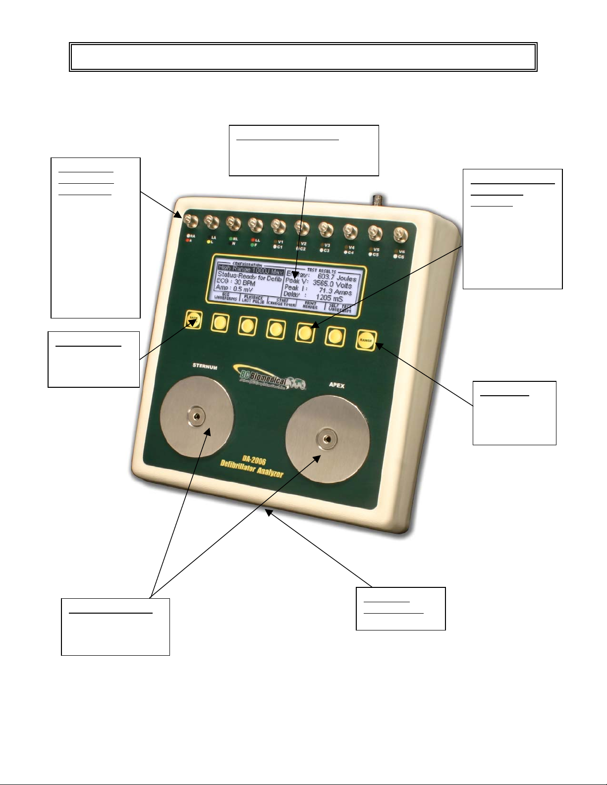
This section looks at the layout of a DA-2006 and gives descriptions of the elements that
are present.
LCD Graphical Display:
10 Universal
Patient Lead
Connectors:
RA R
LA L
RL(-) N
LL F
V1 C1
V2 C2
V3 C3
V4 C4
V5 C5
V6 C6
Back Light Key
for turning on
and off the
backlight
Shows Parameters for Test
Data and Waveforms
5 Light Touch Keys
for Dynamic
functions:
These keys are
labeled in the
bottom portion of
the screen and
change function
based on operating
mode.
Range Key for
selecting Defib
input range
high or low and
ace mode
9V Battery
Large Defib Plates:
Fixed 50 Ohm input
load for Defibrillator
testing
13
Compartment
(Back)
Page 16
DA-2006 Series
p
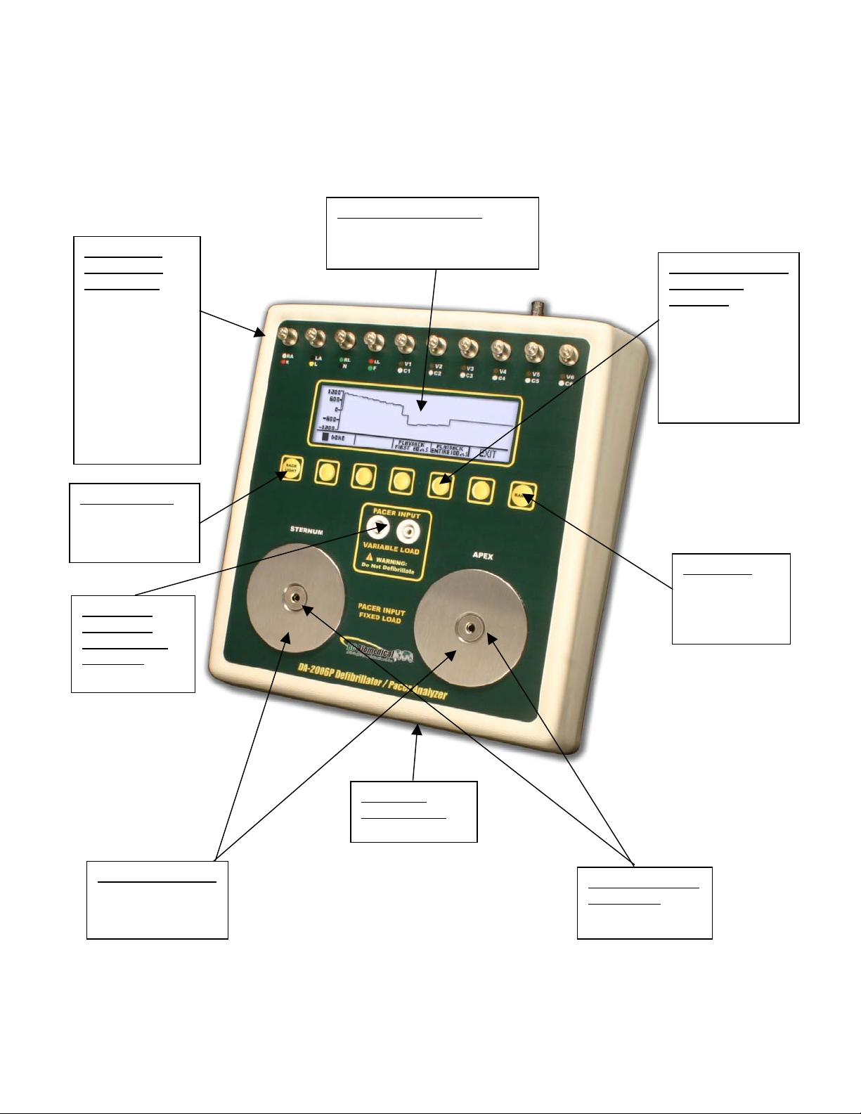
This section looks at the layout of a DA-2006P and gives descriptions of the elements that
are present.
10 Universal
Patient Lead
Connectors:
RA R
LA L
RL(-) N
LL F
V1 C1
V2 C2
V3 C3
V4 C4
V5 C5
V6 C6
LCD Graphical Display:
Shows Parameters for Test
Data and Waveforms
5 Light Touch Keys
for Dynamic
functions:
These keys are
labeled in the
bottom portion of
the screen and
change function
based on operating
mode.
Back Light Key
for turning on
and off the
backlight
Pacemaker
Input Jacks
Variable Load
(optional):
50-2300 Ohms
Large Defib Plates:
Fixed 50 Ohm
input load for
Defibrillator testing
Range Key for
selecting Defib
input range
high or low and
ace mode
9V Battery
Compartment
(Back)
Pacer Input Jacks
Fixed Load:
50 Ohms
14
Page 17
Overview
A
cro
r
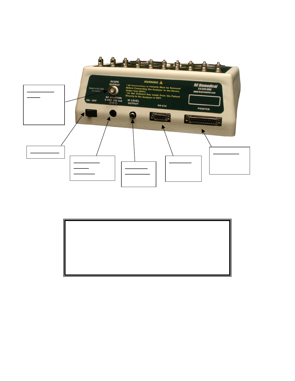
This section looks at the layout of the back and gives descriptions of the elements that are
present.
Oscilloscope
output
BNC connector
for easy
viewing of input
waveforms
Power Switch
Parallel Port
C Adaptor/
Battery
Eliminator
2.1 mm Mi
Serial Port
High Level
ECG output
RCA Jack
Female 9-Pin
D-Sub
Connecto
Female 25-Pin
D-Sub
Connector
NOTE
The DA-2006 and the DA-2006P offer the same
features, with the DA-2006P having the addition
of a Transcutaneous Pacemaker Analyzer
function (See Pacemaker Analyzer section for
more details).
15
Page 18

DA-2006 Series
General Operation
The unit is controlled by 7 light touch keys. They allow the user to move around within the
displayed parameters, select the desired options, choose a specific category and control
the setup for the unit. When a key is depressed there is an audio click when it is accepted,
or a razz tone if the key is invalid.
A large LCD graphics display with backlight provides the user with information about the
current status of the device configuration options, test results and more. The display
identifies the function of each key on a dynamic basis. As the operation mode changes,
the keys change to suit the operating mode.
Range Key
The key scrolls through the ranges of the DA-2006 Series analyzers. Depressing
the key will allow the user to select between High Defibrillator Range (1000J max), Low
Defibrillator Range (50J max) and Pacemaker Range. The default mode on power up is
High Defibrillator Range.
Backlight Key
The Graphic LCD display may be viewed with or without the backlight. Depressing any key
will activate the backlight. However, since the backlight will drain the battery if left on, it will
automatically shut off after 5 seconds when running on battery power.
The key is provided to toggle the backlight on or off at any time.
16
Page 19
Overview
Function Keys
There are five keys that are used to provide general operational control. The
functions of the keys vary depending on the current screen. The section of the screen
just above the key indicates its current meaning.
NOTE: Only functions that are available to the user will be visible at any given time.
Sample Function Key Labeling
ECG Waveforms
The microprocessor has stored in its memory all of the digitalized waveforms. It sends the
waveforms to a D/A converter, which generates an accurate analog representation. The
waveform is then sent through resistor networks, developing the appropriate signals on the
output terminals.
17
Page 20

DA-2006 Series
Universal Patient Lead Connectors
The 10 Universal Patient Lead Connectors allow for 12 lead ECG simulations. AHA and
IEC color-coded labels are located on the face of the unit to aid in connecting the
corresponding U.S. and International Patient Leads.
AHA Label IEC Label Description
RA R Right Arm
LA L Left Arm
RL N
LL F Left Leg
V1
V2
V3
V4
V5
V6
C1
C2
C3
C4
C5
C6
Right Leg
(reference or ground)
V Leads (V1-V6)
(U.S. and Canada)
also referred to as pericardial,
precordial or unipolar chest leads
Chest Leads (C1-C6)
(International)
18
Page 21

Overview
High Level Output (+)
A high level ECG output signal (200 x Amplitude Setting) is available on the RCA jack
located on the rear of the unit.
Serial Port
A female 9-pin D-Sub connector is provided for the connection of the unit to a PC or laptop
serial port (e.g. Com 1). This link is then used for either remote control or flash
downloading of software upgrades.
Parallel Port
A female 25-pin D-Sub connector is provided for the connection of a printer via a
Centronics parallel interface.
Oscilloscope Output
A BNC connector is provided to connect an oscilloscope to the unit. This output is a 200:1
attenuated version of the input to the Defibrillator Plates.
19
Page 22

DA-2006 Series
Power Switch
A rocker switch is provided on the rear of the unit to turn the power on and off.
Power Supply
The unit utilizes two 9 Volt Alkaline Batteries in the bottom battery compartments. When
the unit detects a LOW BATTERY condition (10% Battery Life), a warning window will
appear once per minute to alert the user. If the batteries are not replaced before they reach
a critical level (0 % Battery Life), the unit will shut down.
Battery Eliminator
The unit has a 2.1 mm micro jack for connecting a 10-Volt AC battery eliminator. The
adapter will power the unit, but will not charge the battery.
20
Page 23
DEFIBRILLATOR ANALYZER
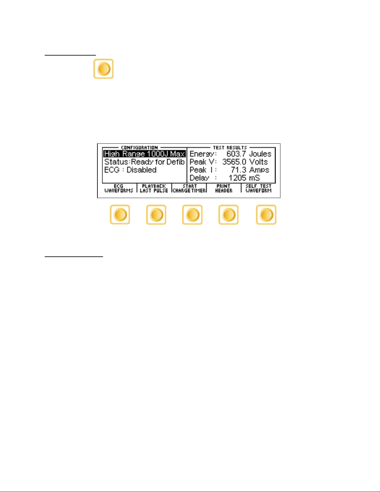
When the DA-2006 is first powered up, the Defibrillator Analyzer MAIN SCREEN will be
displayed. This screen shows the current CONFIGURATION, the TEST RESULTS and the
available FUNCTION KEYS. All defibrillator tests are run from the MAIN SCREEN. When
the unit detects an input of greater than 100 volts on the Defibrillator Plates (20 volts in Low
Range), it will automatically begin a test.
The default configuration is the High Range Defibrillator mode. This mode allows for a
MAIN SCREEN
waveform of up to 1000 Joules to be analyzed.
The following is a sample screen for this mode:
21
Page 24
Defibrillator Analyzer
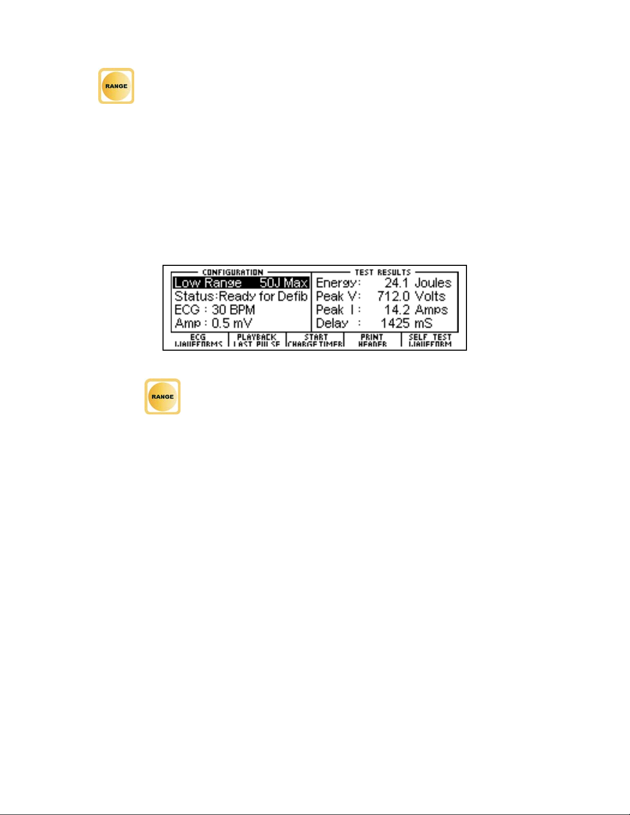
The key may be used to toggle the unit to the Low Range Defibrillator mode. This
mode allows for waveforms up to 50 joules to be analyzed. The Defibrillator Analyzer
works the same in both ranges. The lower range simply provides for a higher resolution for
smaller pulsed.
The following is a sample screen for this mode:
NOTE: The key will also put the DA-2006P into the Transcutaneous Pacemaker
Analyzer mode (See Pacemaker Analyzer section for more information).
22
Page 25

Main Screen
CONFIGURATION
The CONFIGURATION section of the MAIN SCREEN displays the current setup of the unit.
RANGE
The first line displays the range value for the pulse. It may be either 1000 Joules or 50
Joules max. This setting may be changed using the key.
NOTE: This line also allows for the selection of the Pacer Analyzer that is an option
available in the DA-2006P model. The key will toggle to Pacer to put the unit into
the Pacemaker Analyzer mode (See Pacemaker Analyzer section for more information).
STATUS
This line provides information about the current status of the analyzer.
ECG
This line displays the selection that is active on the ECG terminals. This setting may be
changed in the ECG WAVEFORMS screen.
AMP
This line displays the amplitude that has been selected for the ECG terminals. This setting
may be changed in the ECG WAVEFORMS screen.
23
Page 26

Defibrillator Analyzer
TEST RESULTS
The TEST RESULTS section of the MAIN SCREEN displays the results of the last pulse. It
will continue to be displayed until the power is turned off, another test is run or the range is
changed.
NOTE: The unit automatically starts a test when it sees a voltage greater than 100 VDC on
the Defibrillator Plates (20 VDC in Low Range).
NOTE: Test results are immediately sent to the printer port as soon as the data is
available.
ENERGY
This line displays the total energy in the last pulse.
PEAK V
This line displays the peak voltage of the last pulse.
PEAK I
This line displays the peak current of the last pulse.
24
Page 27

Main Screen
DELAY
This line normally displays the delay from the peak of the R wave until the start of the
pulse. The line is replaced by the CHARGE TIME if this test has been run (see START
CHARGE TIMER SCREEN for more information).
CHG TIME
This line displays if the Charge Timer has been run. It shows the time required to charge
the Device Under Test (DUT). This test is started with the key.
25
Page 28

Defibrillator Analyzer
FUNCTION KEYS
The FUNCTION KEYS section of the MAIN SCREEN displays the current functions of the
keys found below the display. These keys allow for navigation to supporting screens and
initiation of specific features.
ECG WAVEFORMS
This key enters the ECG WAVEFORMS screen where all ECG parameters are set.
PLAYBACK LAST PULSE
This key enters the PLAYBACK LAST PULSE screen where a graphical representation of
the last pulse may be viewed and sent out.
START CHARGE TIMER
This key brings up the CHARGE TIMER screen and starts the pre-warn timer. It is used to
test the charge time for the defibrillator.
PRINT HEADER
This key sends the Report Header to the printer.
SELF TEST WAVEFORM
This key sends an internal test pulse to the unit, allowing for the display of the results to
give an indication that the system is working properly.
26
Page 29

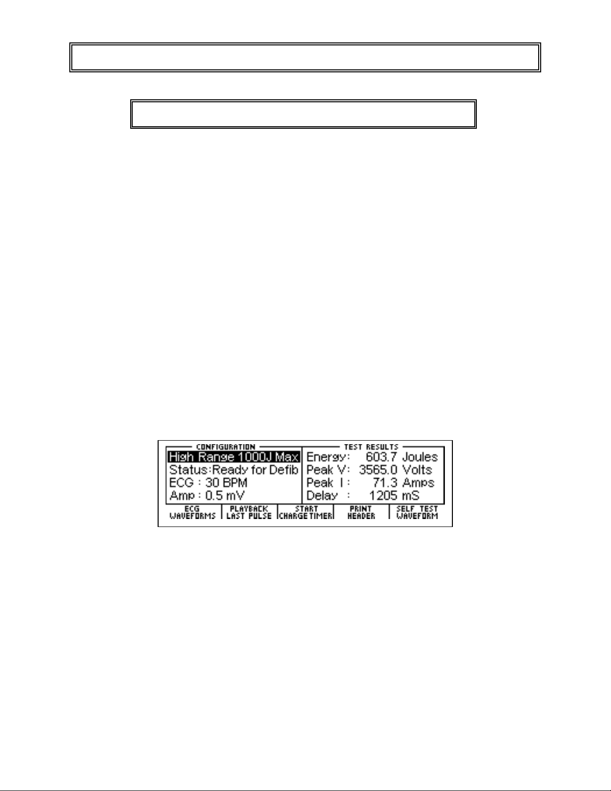
ECG WAVEFORMS SCREEN
The DA-2006 ECG output can be connected in 3, 5 or 12 lead configurations. Pressing the
key from the MAIN SCREEN will allow the user to configure the waveform that
is used for the ECG output.
The following is a sample of the ECG waveform configuration screen:
ECG GROUP WAVEFORM
Disabled None
30,40,45,60,80,90,
NSR
AED
Arrhythmias
Performance
100,120,140,160,
180,200,220,240,
260,280,300 BPM
Asystole
Coarse Vfib
Fine Vfib
Multifocal Vtach 140
Miltifocal Vtach 160
Polyfocal Vtach 140
Polyfocal Vtach 160
SupraVent Tach 90
Vfib
Afib
Second Deg Block
RBBB
PAC
PVC Early
PVC STD
PVC R on T
MF PVC
Bigeminy
Run of 5 PVC
Vtach
0.125, 2 Hz Square
2, 2.5 Hz Triangle
0.1,0.2,0.5,5,10,40,5
0,60,100 Hz Sine
30, 60, 120 BPM
Pulse
AMPLITUDE
Lead I 0.35 mV Lead II 0.5 mV
Lead I 0.70 mV Lead II 1.0 mV
Lead I 1.05 mV Lead II 1.5 mV
Lead I 1.40 mV Lead II 2.0 mV
27
Page 30

Defibrillator Analyzer
The ECG Group, Waveform and Amplitude can be selected using to highlight
the parameter and using to open a drop down menu of all the options for the
highlighted parameter.
Use to scroll to the desired option. Then is used to accept the
new setting. The key can be used to return to the ECG waveform
configuration screen without making a new selection.
The key is used to return to the MAIN SCREEN.
28
Page 31

ECG Waveforms Screen
The following is a brief description of how the DA-2006 simulates the available Arrhythmias:
Abbreviation Arrhythmia Description
Irregular waveform with no real
Vent Fib –
Fine
Atrial Fib
2nd Deg Heart
Block
Rt Bundle
Branch Block
PAC
PVC Early
PVC Std
PVC R on T
Multifocal
PVCS
Ventricular Fibrillation
Artial Fibrillation
Second Degree Heart Block
Right Bundle Branch Block
Premature Atrial Contraction
Early Type 1
Premature Ventricular Contraction
Standard Type 1
Premature Ventricular Contraction
R on T Type 1
Premature Ventricular Contraction
Multifocal
Premature Ventricular Contraction
P-wave or clear R-R interval and a low
signal level
(Continuous)
Absence of P-wave, irregular P-R
interval rate and a high level signal
(Continuous)
80 BPM with increasing
P-R interval for four beats
(160, 220, 400, 470 ms)
followed by a P wave without a QRS
(Continuous)
80 BPM with Normal P-wave and P-R
interval but wider QRS complexes
(Continuous)
NSR of 80 BPM with Periodic
Abnormal 25 % early P waves
(PAC, 7 NSR)
(Continuous)
NSR of 80 BPM with periodic left focus
premature ventricular beats with 33%
premature timing
(PVC Type 1, 9 NSR)
(Continuous)
NSR of 80 BPM with periodic left focus
premature ventricular beats with 20%
premature timing
(PVC Type 1, 9 NSR)
(Continuous)
NSR of 80 BPM with periodic left focus
premature ventricular beats with 65%
premature timing, placing R on the
previous T
(PVC Type 1, 9 NSR)
(Continuous)
NSR of 80 BPM with Type 1 and Type
2 PVCs (PVC Type 1, 2 NSR, PVC
Type 2, 2 NSR)
(Continuous)
29
Page 32

Defibrillator Analyzer
Abbreviation Arrhythmia Description
NSR of 80 BPM with every other beat
Bigeminy
Run of 5
PVCs
Vent Tach
Bigeminal Rhythm
Run of 5 Premature Ventricular
Contractions
Ventricular Tachycardia
a Type 1 PVC
(Continuous)
NSR of 80 BPM with periodic group of
5 Type 1 PVCs
(5 PVC Type 1, 36 NSR)
(Continuous)
160 BPM, No P-wave,
Beats similar to Type 1 PVC
(Continuous)
30
Page 33

PLAYBACK LAST PULSE SCREEN
The DA-2006 can display a graphical representation of the last pulse. This screen may be
accessed by pressing the key from the Defibrillator Analyzer MAIN
SCREEN. The playback allows the user to view the Defibrillator pulse in a time-expanded
form. Samples are stored internally at 0.1 ms intervals. The PLAYBACK LAST PULSE
SCREEN shows these samples expanded by a time factor of 200.
In playback mode, the samples are shown on the display and sent out the ECG leads,
Defibrillator Plates, and the High Level output. The following is a sample of the waveform
that is shown in the display:
The scale shown on the screen is automatically adjusted to provide the maximum
resolution available.
The key can be used to pause the playback at any point.
This key replaces the key when applicable.
The key can be used to play (continue) the waveform if it has been paused.
This key replaces the key when applicable.
31
Page 34

Defibrillator Analyzer
The key starts a playback of only the first 20 ms of the waveform.
The key starts a playback of the entire 100 ms of the waveform.
At any time, the key or key can be depressed to return to the
MAIN SCREEN.
32
Page 35

START CHARGE TIMER SCREEN
A special timer has been incorporated into the DA-2006 to analyze the charging circuit of
the Device Under Test (DUT). The START CHARGE TIMER SCREEN can be accessed
by pressing the key from the MAIN SCREEN. To synchronize the charge
timer with the defibrillator charge time, a Pre-Warning Countdown period is started. When
the timer reaches zero, the defibrillator charge should be initiated. The following is an
example of the countdown timer:
When the timer reaches zero, a beep will sound and the charge timer will begin counting
up. The following is an example of the count up timer:
33
Page 36

Defibrillator Analyzer
The DUT should be discharged as soon as it becomes charged. When the DUT is
discharged, the timer will automatically stop. The display will show the results of the
Defibrillator pulse analysis as well as the time required to charge the DUT:
Charge Timer
Results
At any time, the key can be depressed to end the timer and return to the
MAIN SCREEN.
34
Page 37

PRINT HEADER
The DA-2006 provides a header for recording test data as well as the results of each pulse
that is discharged into the unit. Test results are immediately sent to the printer port as soon
as the data is available. The header is sent by pressing the key from
the MAIN SCREEN.
The status line of the configuration section will indicate that the header has been sent to the
printer.
35
Page 38

Defibrillator Analyzer
The following is the print header and sample data that are used for the Defibrillator
Analyzer mode.
NOTE: Printing the header also resets the test number printed on the data sheet.
NOTE: In the test results, the user must manually write the power setting of the DUT.
36
Page 39

SELF TEST WAVEFORM
The DA-2006 has built in test waveforms that will give an indication that the system is
working properly. The self test waveform may be sent by pressing the key
from the MAIN SCREEN.
After the waveform has been sent, the results will be reflected in the test results section of
the MAIN SCREEN and the PLAYBACK LAST PULSE SCREEN. The self test waveform is
not calibrated, but will provide a waveform that is approximately 125 Joules when
configured for the High Range and 5 Joules when configured for the Low Range.
The following is an example of the MAIN SCREEN with the results of the self test
waveform:
The following is an example of the PLAYBACK LAST PULSE SCREEN, showing a
graphical representation of the self test waveform:
37
Page 40

Defibrillator Analyzer
This page intentionally left blank.
38
Page 41

The DA-2006 will analyze the pulse output of a monophasic or biphasic defibrillator. The
RUNNING A DEFIBRILLATOR TEST
WARNING
All connections to patients must be removed
before connecting the Device Under Test (DUT)
to the Analyzer. A serious hazard may occur if
the patient is connected when testing
with the Analyzer.
Do not connect any leads from the patient
directly to the Analyzer or DUT.
INTRODUCTION
primary measure of the output is the Energy that it contains. Other information deals with
the maximum voltage and current as well as the pulses timing with respect to the R-wave.
The human body has characteristic impedance that may vary, but 50 ohms is used for
comparative defibrillator testing. The DA-2006 has a large internal 50 ohm non-inductive
resistor to simulate a body. It is sized to accept repeated pulses at the maximum
energy levels.
39
Page 42

Defibrillator Analyzer
The energy contained in a pulse is determined mathematically based on the fact that
the energy is defined as the integral of the power curve. The following formulas
describe the basic computation:
E = P dt
P = V
2
/ R => E = V2 / R dt = V2 dt / R
This computation is implemented digitally by taking timed samples of the voltage every
100 µsec for 100 msec (1000 readings). Each value is then squared and divided by the
resistance (50 ohms). The sum of these 1000 values times 10 is then the Energy in
Joules (Watt Seconds) contained in the pulse.
40
Page 43

Running a Defibrillator Test
The setup for a Defibrillation Test is dependent on the physical hardware involved. For
the sake of this example we will assume a standard defibrillator with 5 lead ECG.
DEFIBRILLATION TEST
WARNING
(1) Connect ECG leads to the corresponding universal connector on the DA-2006.
This section is provided as a guide to familiarize
the user with the DA-2006 Series. It is not
intended to provide the necessary test sequence
for every Defibrillator. The user must consult the
manufacturer’s manual for each DUT to
determine the correct test procedure to follow.
The connectors are marked with both the AHA and International color codes.
(2) Turn on the DA-2006.
(3) The unit will come up in the “High Range Defibrillator “ mode. This range is used
for normal adult testing.
NOTE: If it is desirable to run a test at 50 Joules or less with a peak
voltage of 1200 volts or less, the unit may be changed to the “Low Range
Defibrillator” mode using the key.
(4) Select “Ventricular Fibrillation” from the ECG WAVEFORM SCREEN with an
amplitude of 1 mv. This is necessary for most automatic defibrillators.
41
Page 44

Defibrillator Analyzer
(5) Place the Defibrillator Paddles on the DA-2006 contact plates. The APEX is on
the right and the STERNUM is on the left.
NOTE: Reversing the paddles will not cause any damage to the unit or
error in the energy reading. However, it will cause the polarity of the
oscilloscope output and the playback waveform to be reversed.
(6) Holding the paddles firmly in place, charge the Defibrillator and discharge it into
the DA-2006.
Observe all precautions noted by the Defibrillator
WARNING
Manufacturer when using the Defibrillator.
(7) The DA-2006 will automatically sense the voltage rise across the internal 50 ohm
load and begin taking readings. After the sampling is done (100 ms) the unit will
compute and display the results.
a. The power pulse is available at the oscilloscope output in real time with a
200:1 signal attenuation.
b. After the computation, the pulse is automatically played back at a 200:1
time base expansion (200 times slower) on both the ECG leads and the
Paddle plates. The signal level is 1 mv per 1000 volts on Lead 1.
c. At the same time, the test results are sent to the printer.
42
Page 45

Running a Defibrillator Test
(8) The Status line will change to indicate the various steps as they are being done.
(9) At the end of the process the results are continuously displayed in the Test
Results section of the MAIN SCREEN. They will remain there until another test
is performed, the range is changed or the power is turned off.
(10) The user may repeat the playback of the waveform at any time by changing to
the PLAYBACK LAST PULSE SCREEN using the key. In this
screen the pulse may be viewed in 20 msec segments and paused for review.
NOTE: The pulse is sent to the ECG and Paddle outputs at the same time
it is being displayed on the screen.
43
Page 46

Defibrillator Analyzer
This page intentionally left blank.
44
Page 47

Running a Defibrillator Test
A Cardioversion Test is simply an energy test with special attention being given to the
timing. The DA-2006 continuously monitors for the R-wave timing and displays, if
possible, the delay between the R-wave and the pulse. In Cardioversion testing, the
Defibrillator is set to deliver a pulse based on a specific delay after the R-wave.
CARDIOVERSION TEST
WARNING
This section is provided as a guide to familiarize
the user with the DA-2006 Series. It is not
intended to provide the necessary test sequence
for every Defibrillator. The user must consult the
manufacturer’s manual for each DUT to
determine the correct test procedure to follow.
(1) Connect ECG leads to the corresponding universal connector on the DA-2006.
The connectors are marked with both the AHA and International color codes.
(2) Turn on the DA-2006.
(3) The unit will come up in the “High Range Defibrillator “ mode. This range is used
for normal adult testing.
NOTE: If it is desirable to run a test at 50 Joules or less with a peak
voltage of 1200 volts or less, the unit may be changed to the “Low Range
Defibrillator” mode using the key.
45
Page 48

Defibrillator Analyzer
(4) Select the desired ECG Waveform and Amplitude to be tested from the choices
on the ECG WAVEFORM SCREEN.
(5) Set the Defibrillator to Synchronized Cardioversion mode.
(6) Place the Defibrillator Paddles on the DA-2006 contact plates. The APEX is on
the right and the STERNUM is on the left.
NOTE: Reversing the paddles will not cause any damage to the unit or
error in the energy reading. However, it will cause the polarity of the
oscilloscope output and the playback waveform to be reversed.
(7) Holding the paddles firmly in place, charge the Defibrillator and discharge it into
the DA-2006.
WARNING
Observe all precautions noted by the Defibrillator
Manufacturer when using the Defibrillator.
46
Page 49

Running a Defibrillator Test
(8) The DA-2006 will automatically sense the voltage rise across the internal 50 ohm
load and begin taking readings. After the sampling is done (100 ms) the unit will
compute and display the results.
a. The power pulse is available at the oscilloscope output in real time with a
200:1 signal attenuation.
b. After the computation, the pulse is automatically played back at a 200:1
time base expansion (200 times slower) on both the ECG leads and the
Paddle plates. The signal level is 1 mv per 1000 volts on Lead 1.
c. At the same time, the test results are sent to the printer.
(9) The Status line will change to indicate the various steps as they are being done.
(10) At the end of the process the results are continuously displayed in the Test
Results section of the MAIN SCREEN. They will remain there until another test
is performed, the range is changed or the power is turned off.
NOTE: Special note should be made of the “Delay: xxx msec” line in the
results. This will show the delay between the peak of the R-wave and the
start of the Pulse.
(11) The user may repeat the playback of the waveform at any time by changing to
the PLAYBACK LAST PULSE SCREEN using the key. In this
screen the pulse may be viewed in 20 msec segments and paused for review.
NOTE: The pulse is sent to the ECG and Paddle outputs at the same time
it is being displayed on the screen.
47
Page 50

Defibrillator Analyzer
This page intentionally left blank.
48
Page 51

Running a Defibrillator Test
The charging time of a Defibrillator is nothing more than a measurement of the time
required for the Defibrillator to charge. It is used to test the battery, charging circuitry
and capacitor. The DA-2006 provides a simple way to start and stop the timer. It also
records the results.
This section is provided as a guide to familiarize
CHARGE TIME TEST
WARNING
the user with the DA-2006 Series. It is not
intended to provide the necessary test sequence
for every Defibrillator. The user must consult the
manufacturer’s manual for each DUT to
determine the correct test procedure to follow.
(1) Turn on the DA-2006.
(2) The unit will come up in the “High Range Defibrillator “ mode. This range is used
for normal adult testing.
(3) Set the Defibrillator to its maximum power setting.
(4) Depress the key.
49
Page 52

Defibrillator Analyzer
(5) While the Pre-Warning Countdown is running, place the Defibrillator Paddles on
the DA-2006 contact plates. The APEX is on the right and the STERNUM is on
the left.
NOTE: Reversing the paddles will not cause any mage to the unit or error
in the energy reading. However, it will cause the polarity of the
oscilloscope output and the playback waveform to be reversed.
(6) Holding the paddles firmly in place, wait until the Pre-Warning Countdown
equals zero and then immediately start charging the Defibrillator.
(7) As soon as the DUT is fully charged, discharge it into the DA-2006.
(8) At the end of the process the results are continuously displayed in the Test
Results section of the MAIN SCREEN. They will remain there until another test
is performed, the range is changed or the power is turned off.
NOTE: The last line in the Test Results section of the screen will show
“Chg Time: xxx.x sec”
Observe all precautions noted by the Defibrillator
Manufacturer when using the Defibrillator.
WARNING
50
Page 53

Running a Defibrillator Test
SHOCK ADVISORY
ALGORITHM TEST
The Shock Advisory Algorithm Test works with the analysis and prompting functions on
automatic and semiautomatic Defibrillators. These circuits look at ECG waveforms and
prompt the user to “Shock” or “No Shock” based on national and international
guidelines. The following table outlines these guidelines:
ECG SIGNALS
Asystole
Supra Ventricular Tachycardia @ 90 BPM
Polyfocal Ventricular Tachycardia @ 140 BPM
Multifocal Venticular Tachycardia @ 140 BPM
SHOCK ADVISORY ALGORITHM TEST
ACTION
No Shock
No Shock
No Shock
No Shock
Coarse Ventricular Fibrillation
Fine Ventricular Fibrillation
Polyfocal Ventricular Tachycardia @ 160 BPM Shock
Multifocal Ventricular Tachycardia @ 160 BPM Shock
Shock
Shock
WARNING
This section is provided as a guide to familiarize
the user with the DA-2006 Series. It is not
intended to provide the necessary test sequence
for every Defibrillator. The user must consult the
manufacturer’s manual for each DUT to
determine the correct test procedure to follow.
51
Page 54

Defibrillator Analyzer
(1) Connect ECG leads to the corresponding universal connector on the DA-2006.
The connectors are marked with both the AHA and International color codes.
(2) Turn on the DA-2006.
(3) The unit will come up in the “High Range Defibrillator “ mode. This range is used
for normal adult testing.
(4) Select the desired AED Waveform and Amplitude to be tested from the choices
on the ECG WAVEFORM SCREEN.
(5) Set the Defibrillator to analyze the ECG waveform in the automatic or
semiautomatic mode.
(6) Observe and record the response of the Defibrillator to the various waveforms.
52
Page 55

TRANSCUTANEOUS PACEMAKER ANALYZER
The DA-2006P can analyze pacemaker pulses as well as determine Refractory periods and
Sensitivity levels of on-demand pacemakers. For maximum versatility, the DA-2006P has
26 internally selectable pacemaker loads ranging from 50 ohms to 2300 ohms. The
DA-2006P can also test the noise immunity of the DUT by generating a 50 or 60 Hz noise
waveform with amplitude up to 100 mV. For sensitivity testing, the DA-2006P can output a
Square, Triangle, or Haversine waveform with widths ranging from 10ms to 200ms.
The key is used to change to the Pacemaker Analyzer mode.
PACE MAIN SCREEN
The Pacemaker Analyzer MAIN SCREEN shows the current CONFIGURATION, the TEST
RESULTS and the available FUNCTION KEYS.
The following is a sample of the PACE MAIN SCREEN:
NOTE: The Test Results section of the PACE MAIN SCREEN contains eight lines of data
that can be toggled to view the first 4 lines or the second 4 lines (See TEST RESULTS
section of manual for more information).
53
Page 56

Pacemaker Analyzer
CONFIGURATION
The CONFIGURATION section of the PACE MAIN SCREEN displays the current setup of
the unit.
LOAD
This line displays the selected load. This setting may be changed in the PACE MODE
SETUP screen. The load choice determines what impedance is used at the pacemaker
input as well as whether the unit uses the Pacer Input Terminals or the Defibrillator Plate
Input Terminals.
NOISE
This line displays the selected noise output. This setting may be changed in the PACE
MODE SETUP screen.
WAVE
This line displays the selected output waveform. This setting may be changed in the PACE
MODE SETUP screen. The selected waveform is the output to the pacer on the ECG
Terminals, Pacer Terminals and Defibrillator Plate Terminals.
54
Page 57

Main Screen
TEST RESULTS
The TEST RESULTS section of the PACE MAIN SCREEN displays the results of the last
test. It will continue to be displayed until the power is turned off or another test is run.
The Test Results section of the PACE MAIN SCREEN contains eight lines of data that can
be toggled to view the first 4 lines or the second 4 lines by pressing the key.
RATE
This line displays the rate of the pacemaker pulse that is present at the selected load.
WIDTH
This line displays the width of the pacemaker pulse that is present at the selected load.
AMP
This line displays the amplitude of the pacemaker pulse that is present at the selected load.
55
Page 58

Pacemaker Analyzer
ENERGY
This line displays the energy of the pacemaker pulse that is present at the selected load.
SENS PADS
This line displays the sensitivity at the pads for the selected waveform during the last
Sensitivity Test.
SENS ECG
This line displays the sensitivity at the ECG leads for the selected waveform during the last
Sensitivity Test.
PACER RP
This line displays the pacer refractory period detected at the selected load during the last
Refractory Period Test.
SENSED RP
This line displays the sensed refractory period detected at the selected load during the last
Refractory Period Test.
56
Page 59

FUNCTION KEYS
Main Screen
The FUNCTION KEYS section of the PACE MAIN SCREEN displays the current functions
of the keys found below the display. These keys allow for navigation to supporting screens
and initiation of specific features.
PACE MODE SETUP
This key enters the PACE MODE SETUP SCREEN where all pace parameters are chosen.
SENSITIVITY TEST
This key activates a Sensitivity Test.
REFRACTORY PERIOD TEST
This key activates a Refractory Period Test.
TOGGLE TEST RESULTS
This key toggles the test result section to view the first 4 lines or the second 4 lines of data.
PRINT MENU
This key enters the PRINT SCREEN that allows the printing of the header or the test data.
57
Page 60

Pacemaker Analyzer
This page intentionally left blank.
58
Page 61

PACER MODE SETUP SCREEN
The DA-2006P can be configured to run a large number of tests under various load
conditions. This screen is used to configure the unit for these tests. The pacemaker
configuration screen is accessed by pressing the key from the PACE MAIN
SCREEN. In this screen, the user can select the desired Load, the output Noise waveform
and the Sensitivity Test waveform.
The following is a sample of the Pacemaker configuration screen:
Defib Plates Input (50Ω)
50 ohms
100 ohms
150 ohms
200 ohms
200 ohms
300 ohms
400 ohms
500 ohms
600 ohms
700 ohms
800 ohms
900 ohms
LOAD
1000 ohms
1100 ohms
1200 ohms
1300 ohms
1400 ohms
1500 ohms
1600 ohms
1700 ohms
1800 ohms
1900 ohms
2000 ohms
2100 ohms
2200 ohms
2300 ohms
Open
NOISE
10 mV 50 Hz
9 mV 50 Hz
8 mV 50 Hz
7 mV 50 Hz
6 mV 50 Hz
5 mV 50 Hz
4 mV 50 Hz
3 mV 50 Hz
2 mV 50 Hz
1 mV 50 Hz
NONE
1 mV 60 Hz
2 mV 60 Hz
3 mV 60 Hz
4 mV 60 Hz
5 mV 60 Hz
6 mV 60 Hz
7 mV 60 Hz
8 mV 60 Hz
9 mV 60 Hz
10 mV 60 Hz
WAVEFORM
10 ms Square
25 ms Square
40 ms Square
100 ms Square
200 ms Square
10 ms Triangle
25 ms Triangle
40 ms Triangle
100 ms Triangle
200 ms Triangle
10 ms SSQ
25 ms SSQ
40 ms SSQ
100 ms SSQ
200 ms SSQ
59
Page 62

Pacemaker Analyzer
The Load, Noise and Waveform can be selected using to highlight the
parameter and using to open a drop down menu of all the options for the
highlighted parameter.
Use to scroll to the desired option. Then is used to accept the
new setting. The key can be used to return to the Pacemaker configuration
screen without making a new selection.
The key is used to return to the PACE MAIN SCREEN.
60
Page 63

The Sensitivity Test is used to determine the smallest waveform that the pacemaker can
detect. For this test, the selected waveform is generated outside of the refractory period of
the pacemaker. The DA-2006P uses a successive approximation approach to determine
the smallest output waveform that can be detected by the pacemaker. The Sensitivity Test
SENSITIVITY TEST
may be initiated by pressing the key from the PACE MAIN SCREEN.
WARNING
While this test is running, the following display will show the progress of the test:
This section is provided as a guide to familiarize
the user with the DA-2006 Series. It is not
intended to provide the necessary test sequence
for every Pacemaker. The user must consult the
manufacturer’s manual for each DUT to
determine the correct test procedure to follow.
At any time, the key can be depressed to stop the test and return to the
PACE MAIN SCREEN.
61
Page 64

Pacemaker Analyzer
At the end of the test, the display will show the pacemaker amplitude sensitivity at the
Pacer Terminals and the ECG Terminals.
62
Page 65

For on-demand pacemakers, the pacemaker should ignore any ECG activity after a pacer
pulse for a specific period of time. This time period is known as the Refractory Period. The
Paced Refractory Period is the time after the pacemaker pulse that ECG activity is ignored.
If an ECG pulse is present inside the refractory period, it is ignored. If an ECG pulse is
detected outside of the refractory period, the pacemaker will re-synchronize to the sensed
ECG pulse. For each sensed ECG pulse, there is a second refractory period. This is
known as the Sensed Refractory Period. It is the period of time after the sensed ECG
pulse that ECG activity is ignored. The Refractory Period Test may be initiated by pressing
the key from the PACE MAIN SCREEN.
REFRACTORY PERIOD TEST
WARNING
While the Refractory Period test is running, the display will indicate the progress of the test:
This section is provided as a guide to familiarize
the user with the DA-2006 Series. It is not
intended to provide the necessary test sequence
for every Pacemaker. The user must consult the
manufacturer’s manual for each DUT to
determine the correct test procedure to follow.
NOTE: It is important that the pulse rate does not change for the duration of the Refractory
Test.
63
Page 66

Pacemaker Analyzer
At any time, the key can be depressed to stop the test and return to the
PACE MAIN SCREEN.
When the test is completed, the display will update with the Paced Refractory Period and
Sensed Refractory Period in the Test Results.
64
Page 67

PRINT MENU SCREEN
The DA-2006P allows the user to print the latest Pacemaker Analysis data or a header.
The PRINT MENU SCREEN is accessed by pressing the key from the
PACE MAIN SCREEN.
The following is an example of the print menu screen:
The header is sent by pressing the key.
The test data is sent by pressing the key.
The key can be depressed to return to the PACE MAIN SCREEN.
65
Page 68

Pacemaker Analyzer
The following is the print header and sample data that are used for the Pacemaker
Analyzer mode:
NOTE: Since Pacemaker pulses are normally continuous, the test data must be printed
manually via the Print Menu.
NOTE: Printing the header also resets the test number printed on the data sheet.
NOTE: In the test results, the user must manually write the power setting of the DUT.
66
Page 69

A
A
MANUAL REVISIONS
Revision # Program # Revisions Made
Rev 01 DT7395CA Preliminary Manual
Rev 02 DT7395CA Miscellaneous Editing Updates
Rev 03 DT7395CA Pictures Updated
Rev 04 DT7395CD Accessories Added
WARRANTY
FROM DEFECTS IN MATERIALS AND WORKMANSHIP UNDER THE SERVICE FOR WHICH THEY
RE INTENDED. THIS WARRANTY IS EFFECTIVE FOR TWELVE MONTHS FROM THE DATE OF
SHIPMENT.
EXCLUSIONS: THIS WARRANTY IS IN LIEU OF ANY OTHER WARRANTY EXPRESSED OR
IMPLIED, INCLUDING, BUT NOT LIMITED TO ANY IMPLIED WARRANTY OF MERCHANTABILITY
OR FITNESS FOR A PARTICULAR PURPOSE.
BC GROUP INTERNATIONAL, INC. IS NOT LIABLE FOR ANY INCIDENTAL OR CONSEQUENTIAL
DAMAGES.
NO PERSON OTHER THAN AN OFFICER IS AUTHORIZED TO GIVE ANY OTHER WARRANTY OR
SSUME ANY LIABILITY.
REMEDIES: THE PURCHASER'S SOLE AND EXCLUSIVE REMEDY SHALL BE: (1) THE REPAIR OR
REPLACEMENT OF DEFECTIVE PARTS OR PRODUCTS, WITHOUT CHARGE. (2) AT THE OPTION
OF BC GROUP INTERNATIONAL, INC., THE REFUND OF THE PURCHASE PRICE.
P:\MANUALS\BCGroup\…\DA-2006_UM_Rev 04.doc
: BC GROUP INTERNATIONAL, INC. WARRANTS ITS NEW PRODUCTS TO BE FREE
LIMITED WARRANTY
67
Page 70

DA-2006 Series
This page intentionally left blank.
68
Page 71

SPECIFICATIONS
ENERGY OUTPUT MEASUREMENT
GENERAL
METHOD
LOAD RESISTANCE
DISPLAY RESOLUTION 0.1 Joules
MEASUREMENT TIME
WINDOW
ABSOLUTE MAX PEAK
VOLTAGE
PULSE WIDTH 100 ms
Biphasic
50 Ohms +/- 1%,
non-inductive (<1 µH)
100 ms
6000 Volts
CARDIOVERSION
DELAY 0 to 6000 ms
RESOLUTION 0.1 ms
ACCURACY +/-2 ms
ENERGY OUTPUT MEASUREMENT
HIGH RANGE
VOLTAGE <5000 Volts
MAX CURRENT 120 Amps
MAX ENERGY 1000 Joules
ACCURACY
TRIGGER LEVEL 100 Volts
PLAYBACK AMPLITUDE 1 mv / 1000 V Lead 1
TEST PULSE 125 Joules +/- 20%
+/-2% of reading for >100 Joules
+/-2 Joules for <100 Joules
ENERGY OUTPUT MEASUREMENT
LOW RANGE
VOLTAGE <1000 Volts
MAX CURRENT 24 Amps
MAX ENERGY 50 Joules
ACCURACY
TRIGGER LEVEL 20 Volts
PLAYBACK AMPLITUDE 1 mv / 1000 V Lead 1
TEST PULSE 5 Joules +/-20%
+/-2% of reading for >20 Joules
+/- 0.4 Joules for <20 Joules
69
Page 72

DA-2006 Series
HIGH MEASURE RANGE 1000:1 amplitude-attenuated
LOW MEASURE RANGE 200:1 amplitude-attenuated
OUTPUT LEAD I & PLATES
SCREEN 200:1 Time Base Expansion
TIMING WINDOW
TEST WAVEFORMS All waveform simulations available
DELAY TIME ACCURACY +/- 1 ms
From 0.1 to 99.9 sec
RATE
ACCURACY +/- 1%
AMPLITUDE 0.5,1.0,1.5,2.0 mv (Lead II)
ACCURACY +/- 2% @ Lead II
HIGH LEVEL 200 times Amplitude
ACCURACY +/- 5%
QRS DURATION 80ms
ENERGY OUTPUT MEASUREMENT
OTHER
OSCILLOSCOPE OUTPUT
WAVEFORM PLAYBACK
SYNC TIME MEASUREMENTS
CHARGE TIME MEASUREMENT
Starts 40 ms before
each R-wave peak
ECG NSR
30,40,45,60,80,90,100,120,140,160,
180,200,220,240,260,280,300 BPM
ECG PERFORMANCE
SINE WAVE 0.1,0.2,0.5,5,10,40,50,60,100 Hz
SQUARE WAVE 0.125, 2.000 Hz
TRIANGLE WAVE 2.000, 2.500 Hz
PULSE WAVE 30,60,120 BPM; 60 ms width
AMPLITUDE 0.5,1.0,1.5,2.0 mv (Lead II)
RATE ACCURACY +/- 1%
AMPLITUDE ACCURACY +/- 2% @ Lead II
ECG GENERAL
LEAD TO LEAD
IMPEDENCE
(RL, LL, RA, LA)
LEAD TO LEAD
IMPEDENCE
(V1-V6)
70
1000 Ohms
1000 Ohms
Page 73

Specifications
ECG ARRHYTHMIA SELECTIONS
Ventricular Fibrillation
Atrial Fibrillation
Second Degree A-V Block
Premature Atrial Contraction
PVC Early
PVC Standard
PVC R on T
Multifocal PVC
Bigeminy
Run of 5 PVCs
Ventricular Tachycardia
SHOCK ADVISORY ALGORITHM TEST
ECG SIGNALS
Asystole
Coarse Ventricular Fibrillation
Fine Ventricular Fibrillation
Multifocal Ventricular Tachycardia @ 140 BPM
Multifocal Ventricular Tachycardia @ 160 BPM
Polyfocal Ventricular Tachycardia @ 140 BPM
Polyfocal Ventricular Tachycardia @ 160 BPM
Supra Ventricular Tachycardia @ 90 BPM
TRANSCUTANEOUS PACEMAKER ANALYZER
TEST LOAD
50,100,150,200,300,400,500,600,700,
RANGE
ACCURACY
800,900,1000,1100,1200,1300,1400,
1500,1600,1700,1800,1900,2000,
2100,2200,2300 Ohms
50 to 1300 Ohm +/-1%
1400 to 2300 Ohm +/-1.5%
TRANSCUTANEOUS PACEMAKER ANALYZER
OSCILLOSCOPE OUTPUT
0 – 150 V 10.24:1 amplitude attenuation
15 – 60 V 41:1 amplitude attenuation
> 60 V 164:1 amplitude attenuation
MAX OUTPUT 200 V
71
Page 74

DA-2006 Series
AMPLITUDE 4 to 300 mA (100 Ohm load)
ACCURACY
RATE 30 to 800 ppm
ACCURACY
PULSE WIDTH 0.6 to 80 ms
ACCURACY
MAX VOLTAGE
TRANSCUTANEOUS PACEMAKER ANALYZER
PULSE MEASUREMENTS
+/-5% or +/-0.5 mA
(whichever is greater)
+/-1% or 2 ppm
(whichever is greater)
+/-1% or +/-0.3 ms
(whichever is greater)
200 V (Variable Load Input Jacks)
15 V (Fixed Load Input Jacks)
PACE LIMIT
PACE LOAD (Ohms) CURRENT (mA)
50 300
100 300
150 300
200 300
300 300
400 300
500 300
600 300
700 286
800 250
900 222
1000 200
1100 182
1200 167
1300 154
1400 143
1500 133
1600 125
1700 118
1800 111
1900 105
2000 100
2100 95
2200 91
2300 87
72
Page 75

Specifications
TRANSCUTANEOUS PACEMAKER ANALYZER
DEMAND SENSITIVITY
WAVEFORMS
Square
SELECTIONS
WIDTH 10,25,40,100,200 ms
ECG OUTPUT
AMPLITUDE – OUT 0 to 4 mv
RESOLUTION – OUT 40 µv
ACCURACY – OUT +/-2%
PACER INPUT (50 TO 400 OHMS)
AMPLITUDE – OUT 0 to 10 mv / 50 Ohms
RESOLUTION – OUT 40 µv
ACCURACY – OUT +/-2%
RATE – IN 30 to 120 ppm
PACER INPUT (500 TO 2300 OHMS & OPEN)
AMPLITUDE – OUT 0 to 100 mv
RESOLUTION – OUT 1mv
ACCURACY – OUT +/-2%
RATE – IN 30 to 120 ppm
DEFIBRILLATOR PLATES
AMPLITUDE – OUT 0 to 10 mv
RESOLUTION – OUT 0.1 mv
ACCURACY – OUT +/-2%
RATE – IN 30 to 120 ppm
Triangle
Haversine
TRANSCUTANEOUS PACEMAKER ANALYZER
50/60 HZ INTERFERENCE TEST SIGNAL
ECG OUTPUT
PACER INPUT 50 OHMS 0,1,2,3,4,5,6,7,8,9,10 mv
PACER INPUT 100 OHMS 0,2,4,6,8,10,12,14,16,18,20 mv
PACER INPUT 150 OHMS 0,3,6,9,12,15,18,21,24,27,30 mv
PACER INPUT 200 OHMS 0,4,8,12,16,20,24,28,32,26,40 mv
PACER INPUT 300 OHMS 0,6,12,18,24,30,36,42,48,54,60 mv
PACER INPUT 400 OHMS 0,8,16,24,32,40,48,56,64,72,80 mv
PACER INPUT > 500 OHMS 0,10,20,30,40,50,60,70,80,90,100 mv
DEFIBRILLATOR PLATES 0,1,2,3,4,5,6,7,8,9,10 mv
0,0.4,0.8,1.2,1.6,2.0,2.4,2.8,
3.2,3.6,4.0 mv
73
Page 76

DA-2006 Series
PACING 20 to 500 ms
SENSING 20 to 500 ms
ACCURACY +/-2 ms
DISPLAY LCD Graphical 256 X 64 Pixels,
ENCLOSURE
WEIGHT
FACE PLATE Lexan, Back printed
OPERATING RANGE 15 to 40 C
STORAGE RANGE -20 to 65 C
TRANSCUTANEOUS PACEMAKER ANALYZER
REFRACTORY PERIOD
DATA INPUT/OUTPUTS
Parallel Printer Port
RS-232C (for computer control)
PHYSICAL
Backlight
3.4 x 9.8 x 10.7 Inches
(86.4 x 249 x 271.8 mm)
Royalite R59
UL Flame Rating 94 V-0
< 5Lbs
(< 2.3 Kg)
POWER
BATTERY ELIMINATOR
ELECTRICAL
Battery, 9 VDC (2 required)
(NE 1604)
Alkaline
BE2006PU (120 VAC) – US
BE2006PE (220 VAC) – Euro
10V, 300 mA DC
74
Page 77

NOTES
75
 Loading...