

1-888-948-2248 | Europe: +353 91 792444
advantech-bb.com
707 Dayton Road | PO Box 1040 | Ottawa, IL 61350
Phone: 815-433-5100 | Fax: 815-433-5109
www.adva ntech- bb.com | E-mail: suppo rt@adva ntech- bb.com
Fast and easy on the web:
www.advantech-bb.com
QUICK START
GUIDE
Docu ment Nu mber : 710-108 64- 00_SC Px11x-DF TB3 _1017qsg
Recommended Accessories
10-30V DC, 2.5W
Power Supply
#MDR-40-24
DIN Rail Adapter Clips
#DRAD35 (pair)
Before you begin, be
sure you have the following:
RS-232 to RS-422/485
Industrial Converters
SCP211-DFTB3, SCP211T-DFTB3 or SCP311T-DFTB3
+ SCPx11x-DFTB3 Converter
+ Quick Start Guide (included)
+ 10-30V DC, 2.5W Power Supply
(not included)
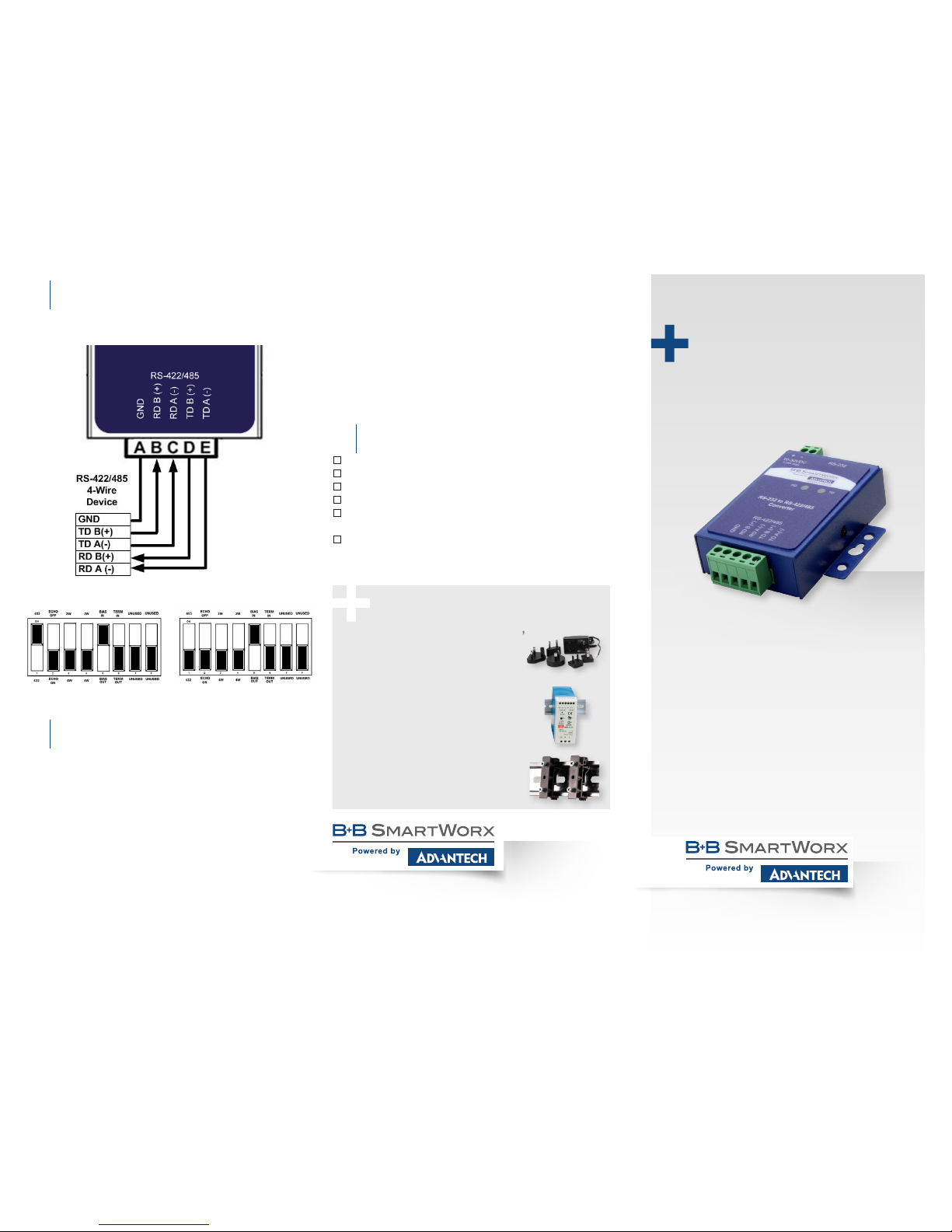
Wiring Examples: RS-422 4-Wire
& RS-485 4-Wire
6
1. In this example, the conver ter is set up to use internal
bias and no termination.
RS-422 4-Wire DIP SwitchRS-485 4-Wire DIP Switch
2. If Termination is necessary on the receive lines, a built in
120 Ω resistor can be switched in using DIP Switch Position
6. In most cases, termination is not required. The default
setting is OFF (termination “out”.)
a. Termination is used to match impedance of a node to the
impedance of the transmission line being used. Termination
increases load on drivers, increases installation complexity,
changes biasing requirements and makes system
modication more difcult. Generally, termination should
only be used for long distances. “If in doubt, leave it out.”
Loop-back Test/Troubleshooting
8
Congure for RS-485 4-wire.
Jumper terminals B to D and C to E.
Connect a PC to the RS-232 port.
TD and RD LED’s are ON when power is applied.
Using hyper terminal or similar program, connect to the
appropriate COM port. Turn off hyper terminal local echo.
Transmit data. The same data should be returned. When
data is sent and looped back, the TD and RD LED’s blink
On and Off indicating data ow.
Bias & Termination
7
1. The circuit can be biased using the built in 1 kΩ pull-up
and pull-down resistors. This is controlled with DIP Switch
Position 5. The default setting is ON (bias resistors “in.”)
a. When an RS-485 network is in an idle state, all nodes are
in listen (Receive) mode. Under this condition, there are
no active drivers on the network. All drivers are tri-stated.
Without anything driving the network, the state of the line
is unknown. If the voltage level at the receiver’s A and B
inputs is less than ±200mV, the logic level at the output of
the receivers will be the value of the last bit received. In
order to maintain the proper idle voltage state, bias resistors
must be applied to force the data lines to the idle condition.
12V DC, 6W, Int’l AC Input,
Stripped/Tinned
Power Supply
#S MI6 -12-V-ST

Product Overview
Specications & Compliances
Control & Indicators
Pinouts & Terminal Identication
1
2
3
SCP211-DFTB3 - Non-isolated, standard temperature
SCP211T-DF TB - Non-isolated, wide temperature
SCP311T-DFTB3 - 2kV isolation, wide temperature
UL Installation Information:
• One Conductor Per Terminal
• Use Copper Wire Only
• Wire Size: 28 to 16 AWG
• Tightening Torque: 5 KG-CM
• Wire Temperature Rating: 105 °C Minimum (sized
for 60 °C Ampacity)
• Surrounding Ambient Air Temperature: 80 °C max.
PRODUCT FEATURES
A
Power Terminal Block 2-position, removable
B
DB9 Female RS-232 (wired DCE)
C
Data LEDs
Green - ON when power is applied.
Blinking to indicate data ow.
D
Mounting Ears
Use for panel mounting. (Use #DRAD35
adapter clip for DIN rail mounting.)
B
RS-422/485 TB 5-position, removable
8-Position DIP Switch - located on back
(Shown in default conguration.)
DB9 Female Connector
DCE (DB9 FEMALE)
PIN SIGNAL DIRECTION
1 DCD –
2 RD Output
3 TD Input
4 DTR –
5 GND –
6 DSR –
7 RTS –
8 CTS –
9 RI –
RS-422/485 4-WIRE
A Ground
B RDB(+)
C RDA(-)
D TDB(+)
E TDA(-)
RS-422/485 2-WIRE
A Ground
B Data B(+)
C Data A(-)
D –
E –
Power Connection
4
1. Connect your external power supply to the 2-position
power terminal block (A). Polarity is indicated on the
front label. The converter will accept 10 to 30 V DC,
2.5W maximum.
2. The terminal block will accept 28 to 12 AWG Wire.
Wiring Example: RS-485 2-Wire
5
RS-485 2-Wire DIP Switch
1. In this example, the conver ter is set up to use internal
bias and no termination.
(NOTE: this is the default factory/shipping conguratio n.)
 Loading...